WO2019044085A1 - Dispositif d'inversion de moule - Google Patents
Dispositif d'inversion de moule Download PDFInfo
- Publication number
- WO2019044085A1 WO2019044085A1 PCT/JP2018/020922 JP2018020922W WO2019044085A1 WO 2019044085 A1 WO2019044085 A1 WO 2019044085A1 JP 2018020922 W JP2018020922 W JP 2018020922W WO 2019044085 A1 WO2019044085 A1 WO 2019044085A1
- Authority
- WO
- WIPO (PCT)
- Prior art keywords
- mold
- cover member
- rotary
- fixed
- cover
- Prior art date
- Legal status (The legal status is an assumption and is not a legal conclusion. Google has not performed a legal analysis and makes no representation as to the accuracy of the status listed.)
- Ceased
Links
Images


Classifications
-
- B—PERFORMING OPERATIONS; TRANSPORTING
- B65—CONVEYING; PACKING; STORING; HANDLING THIN OR FILAMENTARY MATERIAL
- B65G—TRANSPORT OR STORAGE DEVICES, e.g. CONVEYORS FOR LOADING OR TIPPING, SHOP CONVEYOR SYSTEMS OR PNEUMATIC TUBE CONVEYORS
- B65G47/00—Article or material-handling devices associated with conveyors; Methods employing such devices
- B65G47/22—Devices influencing the relative position or the attitude of articles during transit by conveyors
- B65G47/24—Devices influencing the relative position or the attitude of articles during transit by conveyors orientating the articles
- B65G47/248—Devices influencing the relative position or the attitude of articles during transit by conveyors orientating the articles by turning over or inverting them
-
- B—PERFORMING OPERATIONS; TRANSPORTING
- B65—CONVEYING; PACKING; STORING; HANDLING THIN OR FILAMENTARY MATERIAL
- B65G—TRANSPORT OR STORAGE DEVICES, e.g. CONVEYORS FOR LOADING OR TIPPING, SHOP CONVEYOR SYSTEMS OR PNEUMATIC TUBE CONVEYORS
- B65G47/00—Article or material-handling devices associated with conveyors; Methods employing such devices
- B65G47/74—Feeding, transfer, or discharging devices of particular kinds or types
- B65G47/90—Devices for picking-up and depositing articles or materials
-
- B—PERFORMING OPERATIONS; TRANSPORTING
- B65—CONVEYING; PACKING; STORING; HANDLING THIN OR FILAMENTARY MATERIAL
- B65G—TRANSPORT OR STORAGE DEVICES, e.g. CONVEYORS FOR LOADING OR TIPPING, SHOP CONVEYOR SYSTEMS OR PNEUMATIC TUBE CONVEYORS
- B65G7/00—Devices for assisting manual moving or tilting heavy loads
- B65G7/02—Devices adapted to be interposed between loads and the ground or floor, e.g. crowbars with means for assisting conveyance of loads
- B65G7/08—Devices adapted to be interposed between loads and the ground or floor, e.g. crowbars with means for assisting conveyance of loads for tilting the loads
Definitions
- the present invention relates to a mold reversing device capable of reversing a mold mounted on a rotating body having two mold mounting surfaces by 90 °, and in particular, a cover member for covering the vicinity of the outer peripheral surface of the rotating body About.
- Patent Document 1 a rotary structure having a base structure, a mold mounting surface having two open surfaces of 90 ° and rotatably supported on the base structure, and the rotary body can be driven to rotate.
- a mold reversing device capable of inverting the mold placed on one mold mounting surface by 90.degree. On the other mold mounting surface.
- a pair of rotating plates are provided at both ends of the rotating body, and the arc-shaped rolling surfaces of the pair of rotating plates are supported by a plurality of idle rollers of a base structure.
- the pair of rotating plates is connected by a connecting member such as a plurality of tie rods, and a part of a rotational drive mechanism for rotationally driving the rotating body is disposed between the pair of rotating plates. Since approximately one half of the partially cylindrical outer peripheral surface of the rotating body is exposed to the outside, there is a risk that the worker may approach or contact the rotating plate, the connecting member, or the rotational drive mechanism.
- the applicant of the present invention has a mold mounting surface 103a with an open angle of about 90 ° on the rotating body 102 rotatably supported by the base structure 101 of the mold reversing device 100.
- the screen winding device 104 is provided at each end of the base structure 101, the upper end of the screen 105 pulled out from the screen winding device 104 is connected to the end of the rotating body 102, A mold reversing device was put into practical use, in which a portion exposed to the outside of the peripheral surface of 102 was always covered with the screen 105.
- Patent Document 2 the applicant of the present invention raises and lowers at least the lower half of the portion of the peripheral surface of the rotary plate exposed to the outside at both ends of the base structure of the die reversing device.
- a mold reversing device equipped with a possible pair of shutter mechanisms was also proposed.
- Patent Document 2 has a problem that the structure is complicated including the lifting means and the like, the production cost becomes expensive, and a considerable installation space is required, and the practicality is lacking.
- the object of the present invention is to provide a mold reversing device provided with a cover member made of a partially cylindrical metal plate covering the vicinity of the outer peripheral surface of the rotating body on the back side of the two mold mounting surfaces. .
- the mold reversing device comprises a base structure, a rotating body having a mold mounting surface having two open faces with an open angle of about 90 °, and rotatably supported on the base structure.
- a mold reversing device having a rotational driving means capable of rotationally driving the rotating body, wherein the mold placed on one of the mold placement surfaces can be turned 90 ° on the other mold placement surface;
- a partial cylindrical cover member is provided on the back surface side of the two mold mounting surfaces to cover the vicinity of the outer peripheral surface of the rotating body.
- a partial cylindrical cover member is provided on the back surface side of the mold mounting surface of the two surfaces to cover the vicinity of the outer peripheral surface of the rotating body.
- the base structure includes a pair of arc-shaped rotating body supports rotatably supporting both end portions in the rotational axis direction of the rotating body.
- the rotary body is characterized by comprising a pair of rotary plates each having an arc-shaped supported portion supported on the rotary body support portion. According to the above configuration, the pair of arc-shaped supported portions of the rotary body can be rotatably mounted and supported on the pair of rotary body support portions of the base structure.
- the rotary drive means is disposed between the pair of rotary plates and connected to the rotary body and has a predetermined small distance on an arc-shaped outer peripheral portion. It is characterized by having a rack formation which has a plurality of pins attached every other, a sprocket engaged with some of the plurality of pins, and a rotation drive part which can rotationally drive this sprocket. According to the above configuration, the rack-forming body and the rotating body can be rotationally driven by rotationally driving the sprocket by the rotational drive unit and driving the plurality of pins by the sprocket.
- the rotary drive means is disposed between the pair of rotary plates and connected to the rotary body and has a predetermined small distance on an arc-shaped outer peripheral portion.
- a pair of rack formations having a plurality of pins attached to each other, a pair of sprockets respectively engaged with a plurality of pins of a portion of the pair of rack formations, and rotationally driving the pair of sprockets And a possible rotary drive.
- the cover member is formed with an arc-shaped slit corresponding to the rack forming body. According to said structure, when a rotary body rotates, engagement with a sprocket and a rack formation body can be maintained via an arc-shaped slit.
- the cover member is composed of first and second cover members divided by the slit, and the first cover which is longer in the rotational axis direction.
- One end of the member is fixed to the rotary plate and the other end is fixed to the rotary body via the first cover mounting plate, and the middle portion of the first cover member in the rotational axis direction is via the second cover mounting plate It is characterized in that it is fixed to the rotating body, one end of the second cover member is fixed to the rotating plate, and the other end is fixed to the rotating body via the third cover mounting plate.
- the shape can be maintained, and the second cover member includes the rotary plate and the third cover mounting plate
- the shape can be maintained by fixing to
- the cover member is composed of first to third cover members divided by the front and rear slits, and one end of the first cover member is a rotary plate. And the other end is fixed to the rotary body via the first cover mounting plate, one end of the two cover member is fixed to the rotary body via the second cover mounting plate and the other end is the third
- the third cover member is fixed to the rotary body via a cover mounting plate, one end of the third cover member is fixed to the rotary plate, and the other end is fixed to the rotary body via a fourth cover mounting plate.
- the shape can be maintained, and the second cover member is fixed to the second and third cover mounting plates.
- the shape of the third cover member can be maintained by fixing the third cover member to the rotary plate and the fourth cover mounting plate.
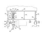
- FIG. 5 is a cross-sectional view taken along line VV of FIG. 3;
- FIG. 6 is a cross-sectional view taken along line VI-VI of FIG.
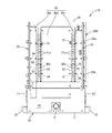
- FIG. 7 is a perspective view of a die reversing device according to a second embodiment.
- It is a front view of the metal mold
- It is a left view of the metal mold
- FIG. 9 is a cross-sectional view taken along line XX in FIG. It is a perspective view of the metal mold
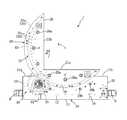
- the die reversing device 1 has a base structure 10, a rotary body 20 rotatably supported on the base structure 10, and rotationally drives the rotary body 20 about a horizontal rotation axis X in the front-rear direction. And a partially cylindrical cover member 40 for covering the vicinity of the outer peripheral surface of the rotating body 20.
- the mold reversing device 1 can flip the mold M placed on one of the mold mounting surfaces 21a and 21b of the rotary body 20 by 90 ° on the other mold mounting surface 21b or 21a.
- FIG. 1 for convenience of explanation, it is assumed that the code L indicates the left, the code R indicates the right, and the code F indicates the front.
- the base structure 10 includes a bottom plate 11, a pair of front plates 12 opposed to each other at intervals, a pair of rear plates 13 opposed to each other at intervals, and a left side plate 14; It has right side plate 15 grade, and is constituted in the shape of a long and thin rectangular parallelepiped which has a predetermined front and back width in the left-right direction.
- a D-shaped notch 16 is formed in the upper portion of the front plate 12 and the rear plate 13 at the center in the left-right direction, and a rotor support 18 for mounting the rotor 20 in the center of the base structure 10 in the left-right direction. Is provided.
- a pair of connecting members 7 having a U-shaped cross section for connecting the front plate 12 and the rear plate 13 are provided.
- a left end box-like portion 17a is formed at the left end portion of the base structure 10
- a right end box-like portion 17b is formed at the right end portion.
- a red rotary lamp 9 is provided below the left end box-like portion 17a and the right end box-like portion 17b.
- an arc-shaped rotary member support 18 along the D-shaped notch 16, the rotary member support 18 being disposed at appropriate intervals in the circumferential direction and having a pair It comprises a plurality of idle rollers 18 a pivotally supported by the front plate 12.
- An arc-shaped rotary member support 18 is formed between the pair of rear plates 13 along the D-shaped notch 16.
- the rotary members 18 are arranged at appropriate intervals in the circumferential direction, and a pair of rotary members 18 are provided.
- a plurality of idle rollers 18 a pivotally supported by the back plate 13 are provided.
- the front idle roller 18a is supported by a pair of front plates 12 by support shafts 18b parallel to the rotation axis X, and the rear idle rollers 18a are supported by the support shaft 18b parallel to the rotation axis X. It is supported by the back plate 13 of the pair. Further, on the outer surface of the front plate 12 and the rear plate 13, a pair of hanging brackets 19 projecting outward are fixed.
- the rotating body 20 has two mold mounting surfaces 21 a and 21 b with an open angle of about 90 ° and is rotatably supported on the front and rear rotary support portions 18 of the base structure 10.
- the rotating body 20 includes a pair of front and rear rotary plates 24 and 25 each having an arc-shaped supported portion 22 rotatably supported by a pair of front and rear rotary body supporting portions 18, and a pair of rotary plates 24, And an L-shaped plate 26 in a front view L-shape joined to each other.
- Two mold setting surfaces 21 a and 21 b are formed on the surface of the L-shaped plate 26.
- two pairs of channel members 26a and 26b for respectively reinforcing the mold mounting surfaces 21a and 21b are joined, and both front and rear end portions of these channel members 26a and 26b It is joined.
- Each of the rotary plates 24 and 25 is formed in an L shape in which the vertically oriented D-shaped portion at the left of the circle and the horizontally oriented D-shaped portion at the lower portion of the circle are integrated.
- Each of the rotating plates 24 and 25 is formed by laminating a plurality of thin steel plates by a plurality of bolts 27.
- the pair of rotating plates 24 and 25 includes an L-shaped plate 26, channel members 26a and 26b, and a longitudinal direction Are connected by a plurality of tie rods 28 extending in Nuts 28 a are screwed to the front and rear end portions of the tie rods 28 outside the rotary plates 24 and 25.
- the rotary drive means 30 can rotationally drive the rack forming body 31 (see FIG. 3), a sprocket 33 engaged with some of the plurality of pins 32 of the rack forming body 31, and the sprocket 33. And an electric motor 34 (rotational drive unit) with a reduction gear.
- the rack forming body 31 is disposed in the middle in the front-rear direction near the rear between the rotary plates 24 and 25 and is connected to the rotary body 20.
- the rack forming body 31 is fixed to the L-shaped plate 26 of the rotating body 20 and the plurality of tie rods 28.
- the electric motor 34 is connected to a control drive unit (not shown).
- the rack forming body 31 is fixed to the pair of pin holding plates 31a and a portion near the outer periphery of the pin holding plates 31a at predetermined small intervals in the circumferential direction and both ends are connected to the pair of pin holding plates 31a.
- a plurality of pins 32 are formed.
- the pin holding plate 31a is a member having a diameter slightly smaller than that of the rotating plates 24 and 25 and substantially the same shape as the rotating plates 24 and 25.
- the pair of pin holding plates 31a are opposed to each other with a predetermined small space therebetween.
- the plurality of pins 32 integrally connect.
- the rotary drive means 30 is configured to be able to rotationally drive the rotary body 20 in the state of FIG. 1 about 90 ° in the counterclockwise direction, and to rotate it back to the original position after the rotation.
- a slanting plate 8 is fixed which covers the sprocket 33 and a part of the electric motor 34 with a reduction gear from above.
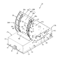
- the cover member 40 is formed of a thin steel plate in a partial cylindrical shape, and is provided so as to cover the vicinity of the outer peripheral surface of the rotary body 20 on the back side of the two mold mounting surfaces 21a and 21b.
- a plurality of bolts 27 for fastening a plurality of laminated thin steel plates are attached in the vicinity of the outer periphery thereof.
- the cover member 40 is disposed at a radial position corresponding to a portion slightly inside of the plurality of bolts 27.
- the cover member 40 is formed with an arcuate slit 40 s for passing the sprocket 33 of the rotational drive means 30.
- the cover member 40 covers the first cover member 40a covering the outer peripheral surface vicinity portion of the rotary body 20 between the slit 40s and the rotary plate 24, and covers the outer peripheral surface vicinity portion of the rotary body 20 between the slit 40s and the rotary plate 25. It is comprised by the 2nd cover member 40b. That is, the cover member 40 is divided into the first cover member 40 a and the second cover member 40 b by the slits 40 s corresponding to the rack forming body 31.
- the cover mounting plates 41 and 42 having substantially the same shape as the rack forming body 31 are provided on the inner side of the rear end portion of the first cover member 40a and the inner side of the middle portion in the front-rear direction.
- the cover mounting plates 41 and 42 orthogonal to X are disposed and fixed to the rotating body 20.
- the front end portion of the first cover member 40a is fixed to the rotary plate 24 via L-shaped pieces 44 arranged at appropriate intervals in the circumferential direction.
- One end of the L-shaped piece 44 is joined to the rotary plate 24, and the other end of the L-shaped piece 44 is fixed to the inner surface of the first cover member 40a by a screw.
- the rear end portion of the first cover member 40a is fixed to the cover mounting plate 41 via L-shaped pieces 45 arranged at appropriate intervals in the circumferential direction.
- One end of the L-shaped piece 45 is joined to the cover mounting plate 41, and the other end of the L-shaped piece 45 is fixed to the inner surface of the first cover member 40a by a screw.
- the cover attachment plates 41 and 42 are the first and second cover attachment plates.
- An intermediate portion (intermediate portion) in the front-rear direction of the first cover member 40a is fixed to the cover mounting plate 42 through L-shaped pieces 46 arranged at appropriate intervals in the circumferential direction.
- One end of the L-shaped piece 46 is joined to the cover mounting plate 42, and the other end of the L-shaped piece 46 is fixed to the inner surface of the first cover member 40a with a screw.
- the rear end portion of the second cover member 40b is fixed to the rotary plate 25 via L-shaped pieces 47 arranged at appropriate intervals in the circumferential direction.
- One end of the L-shaped piece 47 is joined to the rotary plate 25 and the other end of the L-shaped piece 47 is fixed to the inner surface of the second cover member 40b by a screw.
- the front end portion of the second cover member 40b is fixed to the cover mounting plate 43 via L-shaped pieces 48 arranged at appropriate intervals in the circumferential direction.
- One end of the L-shaped piece 48 is joined to the cover mounting plate 43, and the other end of the L-shaped piece 48 is fixed to the inner surface of the second cover member 40b by a screw.
- the cover mounting plate 41 is located near the front side of the rack forming body 31, the cover mounting plate 43 is located near the rear side of the rack forming body 31, and a slit 40s is formed between the cover mounting plates 41 and 43.
- the rotating body 20 is turned counterclockwise.
- the mold placement surface 21b is in a horizontal posture, and the mold M inverted 90 degrees is placed on the mold placement surface 21b.
- the mold M can be inverted by 90 °.
- 180 ° inversion is possible by repeating 90 ° inversion twice.
- the partial cylindrical cover member 40 covering the outer peripheral surface vicinity portion of the rotary body 20 is provided, even if the operator's hand or foot temporarily contacts the cover member 40, the inner side of the rotary body 20 is Since there is no risk of getting caught, safety around the rotating body 20 is significantly improved without causing any injury. Moreover, the partial cylindrical cover member 40 has a simple structure and can be manufactured at low cost, and the installation space is hardly required, so that there is no fear that the die reversing device 1 is enlarged.
- the cover member 40 covers the internal structure of the rotary body 20 and does not expose it to the outside, the appearance of the rotary body 20 is also significantly improved. Further, since the first cover member 40a is configured to be supported by the rotary body 20 via the rotary plate 24 and the cover mounting plates 41 and 42, rigidity is maintained while maintaining the shape of the first cover member 40a, and an object is externally provided. Even if a collision occurs, the shape of the first cover member 40a can be maintained.
- the second cover member 40b is configured to be supported by the rotary body 20 via the rotary plate 25 and the cover mounting plate 43, rigidity is maintained while maintaining the shape of the second cover member 40b, and an object is externally Even if a collision occurs, the shape of the second cover member 40b can be maintained.
- the die reversing device 1A according to the second embodiment is a device suitable for reversing a large-sized die, and this die reversing device 1A will be described based on FIGS. 7 to 10.
- the same reference numerals are given to the same members as in the first embodiment and the description thereof is omitted, and a configuration different from the first embodiment will be described.
- Slits 40s and a rack forming body 31 are provided at the front and the rear of the rotary body 20A of the die reversing device 1A, and a pair of sprockets 33 for driving the rack forming body 31 is provided.
- a set of rotational drive units 34A for rotationally driving The rotational drive means 30A comprises a pair of rack formations 31, a pair of sprockets 33, and a pair of rotational drives 34A.
- the slits 40s and the rack forming body 31 are configured in the same manner as in the first embodiment.
- the front and rear end portions of the sprocket support shaft 35 supporting the pair of sprockets 33 are rotatably supported by the front plate 12 and the rear plate 13.
- the rotational drive unit 34A described above includes an intermediate sprocket 36 mounted on the sprocket support shaft 35 between a pair of sprockets 33, and a reduction gear installed in the left end box portion 17a. It has a motor 37 with a machine, a drive-side sprocket 38 fixed to the end of the output shaft of the motor 37 with a reduction gear, and an endless chain 39 wound around the drive-side sprocket 38 and the intermediate sprocket 36.
- the inclined plate 8A is formed wide in the front and back direction so as to cover the front and rear sprockets 33.
- a partially cylindrical cover member 40A which covers the vicinity of the outer peripheral surface of the rotary body 20A on the back side of the two mold mounting surfaces 21a and 21b.
- the cover member 40A is divided into three cover members 40c, 40d and 40e by the front and rear slits 40s. Therefore, the cover member 40A is between the front cover member 40c (first cover member) that covers the vicinity of the outer peripheral surface of the rotary body 20A between the front slit 40s and the rotary plate 24 and the front and rear slits 40s.
- a cover mounting plate 51 is disposed in the vicinity of the front side of the front slit 40s and is fixed to the rotating body 20A.
- the front end portion of the cover member 40c is fixed to the rotary plate 24 by L-shaped pieces 55 arranged at appropriate intervals in the circumferential direction.
- One end of the L-shaped piece 55 is joined to the rotary plate 24, and the other end of the L-shaped piece 55 is fixed to the inner surface of the front cover member 40c with a screw.
- the rear end portion of the front cover member 40c is fixed to the cover mounting plate 51 by L-shaped pieces 56 arranged at appropriate intervals in the circumferential direction.
- One end of the L-shaped piece 56 is joined to the cover mounting plate 51, and the other end of the L-shaped piece 56 is fixed to the inner surface of the front cover member 40c with a screw.
- a cover mounting plate 52 is disposed near the rear side of the front slit 40s and fixed to the rotary body 20A, and a cover mounting plate 53 is disposed near the front side of the rear slit 40s and fixed to the rotary body 20A There is.
- the front end of the central cover member 40d is fixed to the cover mounting plate 52 by L-shaped pieces 57 arranged at appropriate intervals in the circumferential direction.
- One end of the L-shaped piece 57 is joined to the cover mounting plate 52, and the other end of the L-shaped piece 57 is fixed to the inner surface of the front end of the central cover member 40d with a screw.
- the rear end portion of the central cover member 40d is fixed to the cover mounting plate 53 by L-shaped pieces 58 arranged at appropriate intervals in the circumferential direction.
- One end of the L-shaped piece 58 is joined to the cover mounting plate 53, and the other end of the L-shaped piece 58 is fixed to the inner surface of the rear end of the central cover member 40d with a screw.
- a cover mounting plate 54 is disposed in the vicinity of the rear side of the rear slit 40s and is fixed to the rotating body 20A.
- the rear end portion of the rear cover member 40e is fixed to the rotary plate 25 by L-shaped pieces 59 arranged at appropriate intervals in the circumferential direction.
- One end of the L-shaped piece 59 is joined to the rotary plate 25, and the other end of the L-shaped piece 59 is fixed to the inner surface of the rear cover member 40e with a screw.
- the front end of the rear cover member 40e is fixed to the cover mounting plate 54 by L-shaped pieces 60 arranged at appropriate intervals in the circumferential direction.
- One end of the L-shaped piece 60 is joined to the cover mounting plate 54, and the other end of the L-shaped piece 60 is fixed to the inner surface of the rear cover member 40e with a screw.
- the front slit 40s is formed by the pair of cover mounting plates 51 and 52, and the rear slit 40s is formed by the pair of cover mounting plates 53 and 54.
- the cover attachment plates 51 to 54 correspond to the first to fourth cover attachment plates 51 to 54, respectively.
- the operation and effects of the die reversing device 1A are substantially the same as the operations and effects of the die reversing device 1 of the first embodiment.
- the rotation driving force is strengthened. Large molds can be inverted.
- a chain may be fixed to the circumferential surface of the rack forming body instead of the plurality of pins of the rack forming body of the rotational driving means, and the sprocket engaged with the chain may be rotationally driven.
- the rotating bodies 20 and 20A instead of the rack forming body 31, the same as the rack forming body having a diameter slightly smaller than that of the rotating plates 24 and 25 in the rear side near the rotary plate 24 and the front side near the rotary plate 25.
- the rack formations of the structure may be integrally formed, and the one-piece rack formations may be rotationally driven through the sprockets. With this structure, the number of members of the rack forming body 31 can be reduced.
- the rotary plates 24 and 25 may be made of one steel plate instead of a plurality of steel plates.
Landscapes
- Engineering & Computer Science (AREA)
- Mechanical Engineering (AREA)
- Moulds For Moulding Plastics Or The Like (AREA)
- Specific Conveyance Elements (AREA)
- Attitude Control For Articles On Conveyors (AREA)
Abstract
Le problème décrit par la présente invention est de fournir un dispositif d'inversion de moule pourvu d'un élément couvercle partiellement cylindrique qui est constitué d'une plaque métallique et qui, sur le côté arrière de deux surfaces de placement de moule, recouvre le voisinage d'une surface circonférentielle externe d'un corps rotatif. La solution selon l'invention porte sur un dispositif d'inversion de moule (1) capable d'inverser un moule (M) de 90° et ayant : une structure de base (10) ; un corps rotatif (20) ayant deux surfaces de placement de moule (21a, 21b) et supporté de façon rotative sur la structure de base (10) ; et un moyen d'entraînement en rotation (30) apte à faire tourner le corps rotatif (20) est pourvu d'un élément couvercle partiellement cylindrique (40) qui, sur le côté arrière de deux surfaces de placement de moule (21a, 21b), recouvre le voisinage d'une surface circonférentielle externe du corps rotatif (20). L'élément couvercle (40) est divisé en un premier et un second élément couvercle (40a, 40b) par une fente (40s), le premier élément couvercle (40a) étant fixé à une plaque rotative (24) et à deux plaques de montage de couvercle (41, 42), et le second élément couvercle (40b) étant fixé à une plaque rotative (25) et à une plaque de montage de couvercle (43).
Priority Applications (1)
| Application Number | Priority Date | Filing Date | Title |
|---|---|---|---|
| CN201880055009.9A CN111032537A (zh) | 2017-08-31 | 2018-05-31 | 模具反转装置 |
Applications Claiming Priority (2)
| Application Number | Priority Date | Filing Date | Title |
|---|---|---|---|
| JP2017166435A JP2019043703A (ja) | 2017-08-31 | 2017-08-31 | 金型反転装置 |
| JP2017-166435 | 2017-08-31 |
Publications (1)
| Publication Number | Publication Date |
|---|---|
| WO2019044085A1 true WO2019044085A1 (fr) | 2019-03-07 |
Family
ID=65527324
Family Applications (1)
| Application Number | Title | Priority Date | Filing Date |
|---|---|---|---|
| PCT/JP2018/020922 Ceased WO2019044085A1 (fr) | 2017-08-31 | 2018-05-31 | Dispositif d'inversion de moule |
Country Status (3)
| Country | Link |
|---|---|
| JP (1) | JP2019043703A (fr) |
| CN (1) | CN111032537A (fr) |
| WO (1) | WO2019044085A1 (fr) |
Cited By (5)
| Publication number | Priority date | Publication date | Assignee | Title |
|---|---|---|---|---|
| CN111409218A (zh) * | 2020-04-02 | 2020-07-14 | 常州市新创智能科技有限公司 | 一种芯模翻转移动装置及方法 |
| CN112794038A (zh) * | 2021-02-02 | 2021-05-14 | 常州布鲁科技有限公司 | 一种生产线上用翻包机 |
| CN113636314A (zh) * | 2021-08-31 | 2021-11-12 | 长沙华恒机器人系统有限公司 | 一种用于lng瓶装配的套装翻转机 |
| CN114620487A (zh) * | 2022-03-03 | 2022-06-14 | 安徽高瑞鑫光电科技有限公司 | 成品盖板智能检测设备 |
| CN116461034A (zh) * | 2023-03-05 | 2023-07-21 | 广州市迅兴精密工业有限公司 | 一种汽车配件加工用高精度冲压模具 |
Families Citing this family (1)
| Publication number | Priority date | Publication date | Assignee | Title |
|---|---|---|---|---|
| CN112371218B (zh) * | 2020-11-27 | 2022-03-15 | 新疆西部合盛硅业有限公司 | 一种冶金冶炼用硅锰合金碎块设备 |
Citations (4)
| Publication number | Priority date | Publication date | Assignee | Title |
|---|---|---|---|---|
| US3753505A (en) * | 1971-03-10 | 1973-08-21 | Fmc Corp | Article roll-over device |
| JPH02142707U (fr) * | 1989-05-01 | 1990-12-04 | ||
| JP3001251U (ja) * | 1994-02-19 | 1994-08-23 | 相生精機株式会社 | 金型反転装置 |
| JP2004189425A (ja) * | 2002-12-11 | 2004-07-08 | Biso Co Ltd | 反転装置における駆動機構 |
Family Cites Families (8)
| Publication number | Priority date | Publication date | Assignee | Title |
|---|---|---|---|---|
| JP3473919B2 (ja) * | 1994-11-10 | 2003-12-08 | パスカル株式会社 | 金型反転装置 |
| CN102962715A (zh) * | 2012-11-13 | 2013-03-13 | 大连钛鼎重工有限公司 | 电动筒节翻转台 |
| CN204280651U (zh) * | 2014-10-24 | 2015-04-22 | 富鼎电子科技(嘉善)有限公司 | 翻面机 |
| CN204264947U (zh) * | 2014-11-26 | 2015-04-15 | 咸宁华源印铁制罐有限公司 | 一种卷铁翻包机 |
| CN204416488U (zh) * | 2015-01-13 | 2015-06-24 | 上海奉业机械设备有限公司 | 新型模具翻转机 |
| CN105501912B (zh) * | 2015-12-04 | 2018-02-06 | 沃得精机(中国)有限公司 | 滑块翻转机 |
| CN105438787A (zh) * | 2015-12-17 | 2016-03-30 | 天津市神源凯利集团有限公司 | 钢卷翻转机 |
| JP3207602U (ja) * | 2016-09-09 | 2016-11-17 | パスカルエンジニアリング株式会社 | 金型反転装置 |
-
2017
- 2017-08-31 JP JP2017166435A patent/JP2019043703A/ja active Pending
-
2018
- 2018-05-31 CN CN201880055009.9A patent/CN111032537A/zh active Pending
- 2018-05-31 WO PCT/JP2018/020922 patent/WO2019044085A1/fr not_active Ceased
Patent Citations (4)
| Publication number | Priority date | Publication date | Assignee | Title |
|---|---|---|---|---|
| US3753505A (en) * | 1971-03-10 | 1973-08-21 | Fmc Corp | Article roll-over device |
| JPH02142707U (fr) * | 1989-05-01 | 1990-12-04 | ||
| JP3001251U (ja) * | 1994-02-19 | 1994-08-23 | 相生精機株式会社 | 金型反転装置 |
| JP2004189425A (ja) * | 2002-12-11 | 2004-07-08 | Biso Co Ltd | 反転装置における駆動機構 |
Cited By (8)
| Publication number | Priority date | Publication date | Assignee | Title |
|---|---|---|---|---|
| CN111409218A (zh) * | 2020-04-02 | 2020-07-14 | 常州市新创智能科技有限公司 | 一种芯模翻转移动装置及方法 |
| CN112794038A (zh) * | 2021-02-02 | 2021-05-14 | 常州布鲁科技有限公司 | 一种生产线上用翻包机 |
| CN112794038B (zh) * | 2021-02-02 | 2022-05-17 | 常州布鲁科技有限公司 | 一种生产线上用翻包机 |
| CN113636314A (zh) * | 2021-08-31 | 2021-11-12 | 长沙华恒机器人系统有限公司 | 一种用于lng瓶装配的套装翻转机 |
| CN113636314B (zh) * | 2021-08-31 | 2024-02-06 | 长沙华恒机器人系统有限公司 | 一种用于lng瓶装配的套装翻转机 |
| CN114620487A (zh) * | 2022-03-03 | 2022-06-14 | 安徽高瑞鑫光电科技有限公司 | 成品盖板智能检测设备 |
| CN116461034A (zh) * | 2023-03-05 | 2023-07-21 | 广州市迅兴精密工业有限公司 | 一种汽车配件加工用高精度冲压模具 |
| CN116461034B (zh) * | 2023-03-05 | 2023-11-21 | 广州市迅兴精密工业有限公司 | 一种汽车配件加工用高精度冲压模具 |
Also Published As
| Publication number | Publication date |
|---|---|
| CN111032537A (zh) | 2020-04-17 |
| JP2019043703A (ja) | 2019-03-22 |
Similar Documents
| Publication | Publication Date | Title |
|---|---|---|
| WO2019044085A1 (fr) | Dispositif d'inversion de moule | |
| JP3733176B2 (ja) | 曲げ加工装置 | |
| JP3473919B2 (ja) | 金型反転装置 | |
| TWI535505B (zh) | 翻轉裝置 | |
| KR940006911A (ko) | 컨베이어의 구동장치 | |
| JP5229797B2 (ja) | 木材反転装置 | |
| JP3001251U (ja) | 金型反転装置 | |
| KR20130005056U (ko) | 원통형 구조물의 용접용 롤링 장치 | |
| JP3207602U (ja) | 金型反転装置 | |
| JP4577626B2 (ja) | ベルト伝動装置 | |
| JP2001106481A (ja) | ポスト形ジブクレーン | |
| JP2649017B2 (ja) | ワーク移送装置 | |
| JP5688759B2 (ja) | 倍速コンベヤチェーン及び倍速コンベヤ | |
| KR20080102586A (ko) | 유자형 금속판넬 구조물 성형용 밴딩기 | |
| JP7576817B2 (ja) | ワーク反転装置 | |
| JP4464040B2 (ja) | 反転装置における駆動機構 | |
| CN212399411U (zh) | 一种减速机装配用翻转机构 | |
| JP6496283B2 (ja) | ケーブル送り出し装置 | |
| JP2007084246A (ja) | ローラコンベヤ | |
| JP4948116B2 (ja) | 搬送ローラー走行用連動装置 | |
| JP3126807B2 (ja) | スロットマシンの図柄移動装置 | |
| JPS6245144B2 (fr) | ||
| AU2019100941A4 (en) | Rolling door driving structure capable of changing transmission ratio thereof | |
| JPH06177Y2 (ja) | 管状体屈曲装置 | |
| TWM599729U (zh) | 模具翻轉機 |
Legal Events
| Date | Code | Title | Description |
|---|---|---|---|
| 121 | Ep: the epo has been informed by wipo that ep was designated in this application |
Ref document number: 18851409 Country of ref document: EP Kind code of ref document: A1 |
|
| NENP | Non-entry into the national phase |
Ref country code: DE |
|
| 122 | Ep: pct application non-entry in european phase |
Ref document number: 18851409 Country of ref document: EP Kind code of ref document: A1 |