WO2019054018A1 - クーラント液処理システム - Google Patents
クーラント液処理システム Download PDFInfo
- Publication number
- WO2019054018A1 WO2019054018A1 PCT/JP2018/025187 JP2018025187W WO2019054018A1 WO 2019054018 A1 WO2019054018 A1 WO 2019054018A1 JP 2018025187 W JP2018025187 W JP 2018025187W WO 2019054018 A1 WO2019054018 A1 WO 2019054018A1
- Authority
- WO
- WIPO (PCT)
- Prior art keywords
- sludge
- coolant
- liquid
- filtration device
- filter
- Prior art date
- Legal status (The legal status is an assumption and is not a legal conclusion. Google has not performed a legal analysis and makes no representation as to the accuracy of the status listed.)
- Ceased
Links
Images


Classifications
-
- B—PERFORMING OPERATIONS; TRANSPORTING
- B01—PHYSICAL OR CHEMICAL PROCESSES OR APPARATUS IN GENERAL
- B01D—SEPARATION
- B01D36/00—Filter circuits or combinations of filters with other separating devices
- B01D36/003—Filters in combination with devices for the removal of liquids
- B01D36/008—Means to filter or treat the separated liquid
-
- B—PERFORMING OPERATIONS; TRANSPORTING
- B01—PHYSICAL OR CHEMICAL PROCESSES OR APPARATUS IN GENERAL
- B01D—SEPARATION
- B01D35/00—Filtering devices having features not specifically covered by groups B01D24/00 - B01D33/00, or for applications not specifically covered by groups B01D24/00 - B01D33/00; Auxiliary devices for filtration; Filter housing constructions
- B01D35/14—Safety devices specially adapted for filtration; Devices for indicating clogging
- B01D35/143—Filter condition indicators
-
- B—PERFORMING OPERATIONS; TRANSPORTING
- B23—MACHINE TOOLS; METAL-WORKING NOT OTHERWISE PROVIDED FOR
- B23Q—DETAILS, COMPONENTS, OR ACCESSORIES FOR MACHINE TOOLS, e.g. ARRANGEMENTS FOR COPYING OR CONTROLLING; MACHINE TOOLS IN GENERAL CHARACTERISED BY THE CONSTRUCTION OF PARTICULAR DETAILS OR COMPONENTS; COMBINATIONS OR ASSOCIATIONS OF METAL-WORKING MACHINES, NOT DIRECTED TO A PARTICULAR RESULT
- B23Q11/00—Accessories fitted to machine tools for keeping tools or parts of the machine in good working condition or for cooling work; Safety devices specially combined with or arranged in, or specially adapted for use in connection with, machine tools
- B23Q11/10—Arrangements for cooling or lubricating tools or work
- B23Q11/1069—Filtration systems specially adapted for cutting liquids
-
- B—PERFORMING OPERATIONS; TRANSPORTING
- B01—PHYSICAL OR CHEMICAL PROCESSES OR APPARATUS IN GENERAL
- B01D—SEPARATION
- B01D29/00—Filters with filtering elements stationary during filtration, e.g. pressure or suction filters, not covered by groups B01D24/00 - B01D27/00; Filtering elements therefor
- B01D29/60—Filters with filtering elements stationary during filtration, e.g. pressure or suction filters, not covered by groups B01D24/00 - B01D27/00; Filtering elements therefor integrally combined with devices for controlling the filtration
-
- B—PERFORMING OPERATIONS; TRANSPORTING
- B01—PHYSICAL OR CHEMICAL PROCESSES OR APPARATUS IN GENERAL
- B01D—SEPARATION
- B01D37/00—Processes of filtration
- B01D37/04—Controlling the filtration
- B01D37/041—Controlling the filtration by clearness or turbidity measuring
-
- B—PERFORMING OPERATIONS; TRANSPORTING
- B23—MACHINE TOOLS; METAL-WORKING NOT OTHERWISE PROVIDED FOR
- B23Q—DETAILS, COMPONENTS, OR ACCESSORIES FOR MACHINE TOOLS, e.g. ARRANGEMENTS FOR COPYING OR CONTROLLING; MACHINE TOOLS IN GENERAL CHARACTERISED BY THE CONSTRUCTION OF PARTICULAR DETAILS OR COMPONENTS; COMBINATIONS OR ASSOCIATIONS OF METAL-WORKING MACHINES, NOT DIRECTED TO A PARTICULAR RESULT
- B23Q17/00—Arrangements for observing, indicating or measuring on machine tools
- B23Q17/24—Arrangements for observing, indicating or measuring on machine tools using optics or electromagnetic waves
- B23Q17/248—Arrangements for observing, indicating or measuring on machine tools using optics or electromagnetic waves using special electromagnetic means or methods
- B23Q17/2485—Arrangements for observing, indicating or measuring on machine tools using optics or electromagnetic waves using special electromagnetic means or methods using interruptions of light beams
-
- C—CHEMISTRY; METALLURGY
- C02—TREATMENT OF WATER, WASTE WATER, SEWAGE, OR SLUDGE
- C02F—TREATMENT OF WATER, WASTE WATER, SEWAGE, OR SLUDGE
- C02F1/00—Treatment of water, waste water, or sewage
- C02F1/001—Processes for the treatment of water whereby the filtration technique is of importance
-
- B—PERFORMING OPERATIONS; TRANSPORTING
- B23—MACHINE TOOLS; METAL-WORKING NOT OTHERWISE PROVIDED FOR
- B23Q—DETAILS, COMPONENTS, OR ACCESSORIES FOR MACHINE TOOLS, e.g. ARRANGEMENTS FOR COPYING OR CONTROLLING; MACHINE TOOLS IN GENERAL CHARACTERISED BY THE CONSTRUCTION OF PARTICULAR DETAILS OR COMPONENTS; COMBINATIONS OR ASSOCIATIONS OF METAL-WORKING MACHINES, NOT DIRECTED TO A PARTICULAR RESULT
- B23Q11/00—Accessories fitted to machine tools for keeping tools or parts of the machine in good working condition or for cooling work; Safety devices specially combined with or arranged in, or specially adapted for use in connection with, machine tools
- B23Q11/10—Arrangements for cooling or lubricating tools or work
-
- B—PERFORMING OPERATIONS; TRANSPORTING
- B23—MACHINE TOOLS; METAL-WORKING NOT OTHERWISE PROVIDED FOR
- B23Q—DETAILS, COMPONENTS, OR ACCESSORIES FOR MACHINE TOOLS, e.g. ARRANGEMENTS FOR COPYING OR CONTROLLING; MACHINE TOOLS IN GENERAL CHARACTERISED BY THE CONSTRUCTION OF PARTICULAR DETAILS OR COMPONENTS; COMBINATIONS OR ASSOCIATIONS OF METAL-WORKING MACHINES, NOT DIRECTED TO A PARTICULAR RESULT
- B23Q17/00—Arrangements for observing, indicating or measuring on machine tools
- B23Q17/24—Arrangements for observing, indicating or measuring on machine tools using optics or electromagnetic waves
-
- C—CHEMISTRY; METALLURGY
- C02—TREATMENT OF WATER, WASTE WATER, SEWAGE, OR SLUDGE
- C02F—TREATMENT OF WATER, WASTE WATER, SEWAGE, OR SLUDGE
- C02F2103/00—Nature of the water, waste water, sewage or sludge to be treated
- C02F2103/02—Non-contaminated water, e.g. for industrial water supply
- C02F2103/023—Water in cooling circuits
-
- C—CHEMISTRY; METALLURGY
- C02—TREATMENT OF WATER, WASTE WATER, SEWAGE, OR SLUDGE
- C02F—TREATMENT OF WATER, WASTE WATER, SEWAGE, OR SLUDGE
- C02F2209/00—Controlling or monitoring parameters in water treatment
-
- C—CHEMISTRY; METALLURGY
- C02—TREATMENT OF WATER, WASTE WATER, SEWAGE, OR SLUDGE
- C02F—TREATMENT OF WATER, WASTE WATER, SEWAGE, OR SLUDGE
- C02F2209/00—Controlling or monitoring parameters in water treatment
- C02F2209/003—Downstream control, i.e. outlet monitoring, e.g. to check the treating agents, such as halogens or ozone, leaving the process
-
- C—CHEMISTRY; METALLURGY
- C02—TREATMENT OF WATER, WASTE WATER, SEWAGE, OR SLUDGE
- C02F—TREATMENT OF WATER, WASTE WATER, SEWAGE, OR SLUDGE
- C02F2209/00—Controlling or monitoring parameters in water treatment
- C02F2209/10—Solids, e.g. total solids [TS], total suspended solids [TSS] or volatile solids [VS]
- C02F2209/105—Particle number, particle size or particle characterisation
-
- C—CHEMISTRY; METALLURGY
- C02—TREATMENT OF WATER, WASTE WATER, SEWAGE, OR SLUDGE
- C02F—TREATMENT OF WATER, WASTE WATER, SEWAGE, OR SLUDGE
- C02F2209/00—Controlling or monitoring parameters in water treatment
- C02F2209/44—Time
- C02F2209/445—Filter life
-
- C—CHEMISTRY; METALLURGY
- C02—TREATMENT OF WATER, WASTE WATER, SEWAGE, OR SLUDGE
- C02F—TREATMENT OF WATER, WASTE WATER, SEWAGE, OR SLUDGE
- C02F2301/00—General aspects of water treatment
- C02F2301/04—Flow arrangements
- C02F2301/046—Recirculation with an external loop
-
- C—CHEMISTRY; METALLURGY
- C02—TREATMENT OF WATER, WASTE WATER, SEWAGE, OR SLUDGE
- C02F—TREATMENT OF WATER, WASTE WATER, SEWAGE, OR SLUDGE
- C02F2303/00—Specific treatment goals
- C02F2303/16—Regeneration of sorbents, filters
-
- Y—GENERAL TAGGING OF NEW TECHNOLOGICAL DEVELOPMENTS; GENERAL TAGGING OF CROSS-SECTIONAL TECHNOLOGIES SPANNING OVER SEVERAL SECTIONS OF THE IPC; TECHNICAL SUBJECTS COVERED BY FORMER USPC CROSS-REFERENCE ART COLLECTIONS [XRACs] AND DIGESTS
- Y02—TECHNOLOGIES OR APPLICATIONS FOR MITIGATION OR ADAPTATION AGAINST CLIMATE CHANGE
- Y02P—CLIMATE CHANGE MITIGATION TECHNOLOGIES IN THE PRODUCTION OR PROCESSING OF GOODS
- Y02P70/00—Climate change mitigation technologies in the production process for final industrial or consumer products
- Y02P70/10—Greenhouse gas [GHG] capture, material saving, heat recovery or other energy efficient measures, e.g. motor control, characterised by manufacturing processes, e.g. for rolling metal or metal working
Definitions
- the present invention relates to a coolant processing system for filtering coolant containing sludge and removing sludge from the coolant.
- a coolant liquid treatment system which captures sludge in the coolant liquid by filtration and purifies the coolant liquid.
- the filtration device includes a filter having a mesh smaller than the predetermined particle size of the sludge so that sludge having a predetermined particle size or more does not pass through. Sludge is captured by allowing the coolant to permeate the filter.
- Patent Document 1 discloses a coolant filtration device provided with a backwashing mechanism as a filter cleaning mechanism.
- the backwashing mechanism utilizes a mechanism for removing sludge such as chips adhering to the periphery of the filter by flowing compressed air against the filter in the direction opposite to the normal coolant flow.
- this coolant filtration device is provided with a pressure switch as a means for detecting the clogging state of the filter. When the pressure switch detects that the filter is clogged, the filter cleaning mechanism is configured to clean the filter.
- the coolant filtration device includes a treatment tank for storing the treatment liquid processed by the filtration device, and in the treatment tank, a replenishment time required to replenish the treatment liquid to a predetermined amount is provided. It is measuring. Then, when this measurement time reaches or exceeds a preset set time, an abnormality is notified. As a result, in this coolant filtration device, it is possible to early notify of the replacement time of the filter and the cleaning time of the treatment liquid tank storing the coolant liquid containing the sludge.
- the conventional coolant processing system reports the timing of cleaning and replacement of the filter by detecting an increase in differential pressure and a decrease in filtration processing amount.
- abnormality such as sludge leakage to the treatment liquid side occurs due to damage to the filter
- the differential pressure does not rise and the filtration processing amount does not occur. Therefore, in the conventional coolant processing system, the sludge comes from the filter It is not possible to detect an abnormality that leaks to the processing solution side.
- the present invention is the following coolant processing system.
- An embodiment of the coolant processing system further comprises a processing liquid tank for storing the processing liquid, and the detection means is disposed between the filtration device and the processing liquid tank. Do. According to this feature, leakage of sludge due to damage to the filter can be detected more quickly, so that the effect of the present invention of suppressing the mixing of sludge into the treatment liquid can be further exhibited. Further, when the detection means is installed in the treatment liquid tank, the sludge leaked from the filter is diluted with the treatment liquid in the treatment liquid tank, so that the sensitivity of the detection means is lowered. However, by installing the detection means between the filtration device and the treatment liquid tank, the sludge leaked from the filter is detected before it is diluted in the treatment liquid tank, so the sensitivity of the detection means can be enhanced.
- the detection means is an optical detection means for detecting particles using light.
- the optical detection means can not only detect sludge in the treatment liquid with high sensitivity, but also can measure the particle diameter and number of particles of the sludge, so it is possible to accurately detect the sludge leakage. Therefore, by using an optical detection means as the detection means, for example, the operation is stopped when particles larger than the set particle diameter are detected or when more particles than the set number of particles are detected. Advanced control is possible.
- a coolant processing system provided with a filtration device for filtering coolant liquid containing sludge
- leakage of sludge due to damage to the filter or the like is quickly detected, and treatment liquid treated with the filtration device is obtained. Contamination of sludge can be suppressed.
- the coolant liquid is lubricating oil, water or the like used for processing machines such as cutting and polishing, and may be any of aqueous liquid and oily liquid.
- a processing machine such as a cutting machine, a polishing machine or a grinding machine
- particles such as chips generated by processing such as cutting and polishing are mixed as sludge into the used coolant liquid.
- the coolant processing system of the present invention is a system for removing sludge from coolant containing sludge such as chips.
- the coolant treatment system according to the present invention is a coolant treatment system provided with a filtration device for filtering a coolant fluid containing sludge, and detecting means for detecting particles in the treatment fluid filtered by the filtration device. It is characterized by having.
- FIG. 1 shows the overall configuration of a coolant processing system 1A and a machine tool 100 according to a first embodiment of the present invention.
- the machine tool 100 is a processing machine such as a grinding machine or a cutting machine that uses a coolant liquid, and particles such as chips of various sizes are generated.
- the coolant processing system 1A of the present invention includes a filtration device 2 for filtering a coolant fluid containing sludge, and a detection means 3 for detecting particles contained in the processing fluid filtered by the filtration device 2. Then, the coolant containing the sludge discharged from the machine tool 100 is used in the machine tool 100 again as the cleaned coolant liquid after particles of a predetermined size are removed by the filtering device 2.
- the filtration device 2 is a device for filtering a coolant liquid including sludge discharged from the machine tool 100, and includes a filter.
- the mesh size of the filter is appropriately designed according to the particle diameter of the sludge contained in the coolant, and is, for example, 1 to 30 ⁇ m, more preferably 5 to 20 ⁇ m. By setting the opening of the filter to 1 ⁇ m or more, it is possible to secure a sufficient amount of filtration processing. On the other hand, by setting the mesh size of the filter to 30 ⁇ m or less, the coolant liquid can be sufficiently cleaned, and problems in the machine tool 100 can be prevented.
- the material of the filter is not particularly limited.
- PE polyethylene
- PP polypropylene
- PTFE tetrafluoroethylene
- CA polyacrylonitrile
- PAN polyacrylonitrile
- PES polyethersulfone
- PI polysulfone
- PS aluminum oxide
- alumina Al 2 O 3 zirconium oxide
- zirconia ZrO 2 zirconium oxide
- titanium oxide titanium oxide
- SUS stainless steel
- SPG glass
- An inorganic film etc. are mentioned.
- the shape of the filter may be any shape, for example, plate-like or cylindrical.
- Examples of the filtration method include a total amount filtration method of filtering the whole amount of the coolant liquid, and a cross flow method of filtering while flowing the coolant liquid parallel to the membrane surface.
- the filtration method is not particularly limited, and can be appropriately selected in consideration of the power cost of the coolant liquid supply pump, the deposition state of the sludge on the membrane surface, and the like.
- the filter device 2 is preferably provided with a filter cleaning device. Although it does not restrict
- the backwashing apparatus is an apparatus for removing sludge deposited on the filter surface by flowing a fluid in a direction opposite to the flow direction of filtration.
- the scraping device is a device that scrapes sludge accumulated on the filter surface by sliding a scraping member or the like on the filter surface or blowing high pressure air onto the filter surface. It is preferable to use a backwashing apparatus from the viewpoint of excellent washing performance.
- the fluid used for the backwashing device is not particularly limited, and for example, air, a treatment liquid subjected to a filtration treatment, and the like can be used.
- air a treatment liquid subjected to a filtration treatment, and the like.
- the filtration device 2 is preferably provided with means for detecting the clogging state of the filter.
- the pressure switch etc. which measure the differential pressure before and behind a filter are mentioned, for example.
- the filter device 2 may be provided with means for detecting the performance of the filter.
- means for detecting the performance of a filter a means etc. which detect filtration processing amount are mentioned, for example.
- the detection means 3 is a configuration for detecting particles in the treatment liquid filtered by the filtration device 2.
- the detection unit 3 is not particularly limited as long as it can detect particles in the treatment liquid, but, for example, an optical detection unit that detects particles using light, a particle is captured by a magnet, a filter, or the like. Capture detection means etc. which are detected.
- the optical detection means irradiates light to the processing solution passing through the flow path, and detects the scattered light, transmitted light, absorption, reflected light, etc. thereof to detect the size and number of particles in the processing solution. It detects.
- the wavelength of light is not particularly limited, and any wavelength may be used as long as it can detect particles. From the viewpoint of reducing the influence of light absorption on the chromaticity of the treatment liquid, it is preferable to use light of a wavelength of 650 nm or more.
- the minute flow path is a flow path partially branched from the main flow path through which almost all the coolant liquid passes.
- the coolant liquid contains air bubbles in the liquid as it passes through various steps while circulating.
- the measurement unit can be pressurized by a simple device such as a small oil feeder.
- an oil feeder in front of the optical detection means.
- the ability of the oil feeder is preferably adjustable to a pressure of 0.2 MPa or more. By adjusting the supply pressure to 0.2 MPa or more, bubbles affecting the measurement can be removed, and a stable measurement can be realized.
- the supply pressure By adjusting the supply pressure to 0.2 MPa or more, when particles of an unexpected size flow into the microchannel, there is an action of pushing out the particles at high pressure, and clogging of the particles in the microchannel Also has the effect of preventing
- the treatment solution is allowed to pass through the measurement unit at a flow rate controlled to be constant, and the treatment solution is irradiated with laser light having a wavelength of 680 nm.
- the irradiated laser light passes through the measurement unit and is detected by a light detector such as a photodiode.
- a shadow is detected by the light detector in order to shield the laser light.
- photoelectric conversion is performed according to the size of the shadow of the particles, and the area derived from the amount of voltage drop caused by the blocked photoelectric amount is converted into a circle, and the diameter is treated as the size of contamination. Can.
- the optical detection means can detect the particle diameter, the number of particles, etc. of the particles in the treatment liquid with high sensitivity.
- the presence or absence of the sludge leakage in the filtration device 2 is determined by the particle diameter and number of particles in the treatment liquid detected by the optical detection means.
- sludge leakage for example, it is judged that sludge leakage has occurred when particles larger than the set particle diameter are detected or when more particles than the set number of particles are detected.
- Control such as stopping the operation of the filtration process 2 is performed.
- Such control may be performed by, for example, a control unit such as a computer, or the operator may stop the operation of the filtration device 2 by notifying the operator of sludge leakage by an alarm.
- the capture detection means captures and detects particles by capture means for capturing particles, such as a magnet and a filter.
- capture means for capturing particles such as a magnet and a filter.
- a method of detecting the trapping state of particles for example, there is a method of providing a monitoring window in the flow channel and monitoring the state of the trapping means, a method of periodically decomposing and observing the state of the trapping means.
- the capture detection means can easily determine the presence or absence of leakage without using an expensive optical detection means.
- FIG. 2 shows the structures of a coolant processing system 1B and a machine tool 100 according to a second embodiment of the present invention.
- the processing liquid tank 4 for storing the processing liquid filtered by the filtering device 2 and the processing target for storing the coolant liquid including the sludge discharged from the machine tool 100
- a liquid tank 5 is provided in the coolant liquid processing system 1B of the second embodiment.
- an optical detection means 3A is installed as a detection means.
- the coolant liquid is supplied from the processing liquid tank 4 to the machine tool 100 by the pump P1 installed in the flow path L4.
- the coolant liquid including the sludge used in the machine tool 100 is collected in the liquid tank 5 to be treated through the flow path L5, the pretreatment device 6, and the flow path L6.
- the treatment liquid tank 4 when the sludge leaks from the filtration device 2, the sludge is stored in the treatment liquid tank 4, so that it is possible to prevent large particles and the like from immediately flowing into the machine tool 100.
- the coolant liquid including the sludge collected in the liquid tank 5 to be treated is sucked up by the pump P2 installed in the flow path L3 and supplied to the filtration device 2.
- the treatment liquid processed by the filtration device 2 is supplied to the treatment liquid tank 4 through the flow path L1.
- a part of the processing liquid is supplied to the processing liquid tank 4 via the branched flow path L2 (micro flow path).
- An optical detection means 3A is installed in the flow path L2, and the optical detection means 3A detects whether or not particles are mixed in the treatment liquid processed by the filtration device.
- Detecting particles in the processing liquid before the processing liquid is supplied to the processing liquid tank 4 by installing the optical detection means 3A in the flow path L2 between the filtering device 2 and the processing liquid tank 4 Can. According to this, since the leakage of sludge due to the damage of the filter and the like can be detected more quickly, the effect of the present invention of suppressing the mixing of the sludge into the treatment liquid supplied to the treatment liquid tank 4 is more exhibited. be able to.
- the optical detection means 3A when the optical detection means 3A is installed at a position after the treatment liquid immediately after being treated by the filtration device 2 such as the treatment liquid tank 4 and the flow path L4 merges with another treatment liquid, the sludge leaked from the filter Since the treatment liquid in the treatment liquid tank 4 is diluted, there is a problem that the sensitivity of the optical detection means 3A is lowered. Therefore, by installing the optical detection means 3A in the flow path L2 between the filtration device 2 and the treatment liquid tank 4, the sludge leaked from the filter is detected before being diluted in the treatment liquid tank 4, There is also an effect of enhancing the sensitivity of the optical detection means 3A.
- the optical detection means 3A may be installed at any position between the filtration device 2 and the machine tool 100. For example, the optical detection means 3A is installed in the processing liquid tank 4, the flow path L4, etc. It is also possible.
- the processing liquid tank 4 and the to-be-processed liquid tank 5 are formed by providing the division wall 7 in one processing tank. Furthermore, the opening 8 is formed in the upper part of the section wall 7, and the processing liquid tank 4 and the to-be-treated liquid tank 5 are connected in the upper space.
- the treatment liquid tank 4 and the treatment liquid tank 5 may be formed as separate tanks, in which case the upper space of the treatment liquid tank 4 and the treatment liquid tank 5 may be communicated by piping or the like.
- the processing liquid in the processing liquid tank 4 can flow into the processing liquid tank 5 as an overflow, so it is processed by the filtering device 2
- the throughput can be set to be larger than the amount of processing liquid supplied to the machine tool 100.
- the processing amount to be processed by the filtration device 2 is larger than the amount of processing liquid supplied to the machine tool 100.
- the ratio (flow rate of liquid to be treated / flow rate of treatment liquid) is 1 or more, preferably 1.2 or more, and more preferably 1.4 or more.
- the pretreatment device 6 for removing the sludge from the coolant liquid including the sludge discharged from the machine tool 100 is provided. Since the load on the filtration device 2 can be reduced by the pretreatment device 6, the frequency of operations such as filter replacement can be reduced.
- the pretreatment device 6 may be any device as long as it is a device for removing sludge.
- a magnet separator that adheres and removes sludge by magnetic force
- a sludge conveyor that scrapes and removes sludge deposited on the bottom of a storage tank
- a cyclone separator that separates and removes sludge by centrifugal force, and the like can be mentioned.
- the preprocessing device 6 may use a plurality of these devices in combination.
- FIG. 3 shows the structures of a coolant processing system 1C and a grinding machine 101 according to a third embodiment of the present invention.
- a liquid temperature adjuster H2 and a liquid level gauge S4 are installed in the processing liquid tank 4.
- the liquid temperature adjusting machine H2 is a device for reducing the temperature of the coolant which has absorbed heat by the grinding machine 101.
- the liquid level meter S4 is an apparatus for detecting an abnormality when the liquid level of the processing liquid tank 4 is lowered and monitoring the supply of the coolant liquid to the grinding machine 101 not to stop.
- a sludge conveyor 61 and a magnet separator 62 are provided as a pretreatment device. Thereby, the load of the filtration device can be reduced.
- the sludge conveyor 61 is provided with a liquid level gauge S2, which is set so that an abnormality such as a decrease in the amount of coolant liquid is detected and the pump P7 can always suck in the coolant liquid.
- the liquid tank 51 is provided inside the liquid tank 5.
- the to-be-treated liquid tank 51 is formed of a tank having a smaller bottom area and a smaller capacity than the to-be-treated liquid tank 5.
- the liquid to be treated tank 51 is in communication via a float check valve 52 at a low level of the liquid to be treated tank 5. The float check valve 52 is closed in a floating state, and the coolant is allowed to flow from the liquid tank 5 into the liquid tank 51 when the float is lowered.
- the coolant liquid containing the sludge in the liquid tank 51 is sucked up by the pump P5 and / or the pump P6, the water level in the liquid tank 51 is lowered, and the liquid level of the liquid tank 51 is a predetermined height.
- the pressure drops to the following level, the float falls following the liquid level, and the coolant flows from the liquid tank 5 into the liquid tank 51.
- a liquid level gauge S3 is provided in the liquid processing tank 51, and if there is an abnormality in the operation, it can be detected immediately.
- the operation and effect of the liquid treatment tank 51 will be described.
- the coolant liquid containing sludge is recovered to the treated liquid tank 5 as in the second embodiment described above, there is a problem that the sludge is deposited at the bottom near the outlet of the flow path L6.
- the liquid tank 5 needs to have a predetermined size so that the coolant can always be supplied to the filtration device, but if this is done, the capacity of the liquid tank 5 becomes large, and the liquid tank 5 is deposited in the liquid tank 5. Because the collected sludge can not be pumped up.
- the area of the bottom surface of the liquid tank 51 is smaller than that of the liquid tank 5, and the area where sludge is deposited is limited.
- the volume is small, a strong flow occurs in the entire inside of the treatment liquid tank 51, and the sludge is transferred in the direction of the pump P5 and / or the pump P6. Therefore, the sludge collected in the treated liquid tank 51 does not deposit on the bottom of the treated liquid tank 51, but is sucked up by the pump P5 and / or the pump P6 and supplied to the filtration device 2A and / or the filtration device 2B. Can.
- each of the filtration devices 2A and 2B is provided with a pressure switch SW that detects clogging of the filter, and a backwashing device that cleans the filter with compressed air supplied from the air compressor AC.
- the filtration devices 2A and 2B are controlled such that while one filtration device is in operation, the operation of the other filtration devices is stopped and the filtration device is cleaned.
- the sludge recovered by the filter cleaning is supplied to the sludge conveyor 61 via the flow path L20 and / or the flow path L21 and discharged out of the system.
- a plurality of filtration devices are preferably installed in parallel.
- the treatment liquid filtered by the filtration devices 2A and 2B is temporarily collected in the liquid collection box 9, and then supplied to the treatment liquid tank 4. Further, the flow path L14 between the liquid collection box 9 and the processing liquid tank 4 is branched, and the flow path L15 is branched to the oil feeder 31 and the optical detection means as in the second embodiment.
- 3A is provided to detect particles contained in the processing solution.
- the treatment liquid filtered by the filtration devices 2A and 2B is temporarily collected in the liquid collection box 9, and the particles in the treatment liquid are detected at the outlet thereof, one for each of the filtration devices 2A and 2B. Particles can be detected by two optical detection means 3A.
- optical detection means may be provided in each of the flow paths L13 and L12 which are the outlets of the two filtration devices 2A and 2B installed in parallel. In this case, if it is determined from the particle size and / or particle number detected by the optical detection means that there is sludge leakage, it is possible to identify the filtration device in which sludge leakage has occurred. This makes it possible to quickly stop the use of the filtration device in which the sludge leaks, so that the effect of the present invention of suppressing the mixing of the sludge into the treatment liquid tank 4 can be further exhibited.
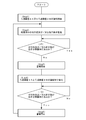
- FIG. 4 shows an example of a control method of the operation of the two filtration devices 2A and 2B.
- Step 1 of starting operation of filtration device 2A or filtration device 2B, particle diameter and / or number of particles in the treatment liquid treated by filtration device 2A or filtration device 2B are monitored by optical detection means 3A
- Step 2 is provided.
- the presence or absence of the sludge leakage is determined from the data obtained by the optical detection means 3A (if1).
- the determination of the presence or absence of sludge leakage is not particularly limited. For example, when filtration is performed using a filter with an opening of 10 ⁇ m, sludge leakage is detected when 10 or more particles of 10 ⁇ m or more in particle diameter are detected per 1 mL. For example, the number of particles having a particle diameter larger than the opening is set, and it is determined that there is sludge leakage if the number is exceeded.
- Step 3 of notifying the sludge leakage by an alarm and then Step 4 of switching the operation of the filtration device 2A and the filtration device 2B are executed.
- the alarm is not particularly limited, but an alarm may be sounded or an alarm may be displayed on the operation screen of the coolant processing system.
- Step 4 is a step of stopping the filtration device being operated and starting the operation of the other filtration device. In addition, what is necessary is just to investigate the cause of the leakage of sludge, perform the appropriate process of filter replacement etc., and the recovered filtration apparatus should be restored.
- Step 5 is performed to stop the alarm.
- Step 5 for stopping the alarm may be automatically stopped or may be stopped by the operator.
- Step 2 is performed to monitor the particle size and / or the number of particles in the treatment liquid by the optical detection means 3A.
- the control method of the operation of the two filtration devices 2A and 2B shown in FIG. 4 is an example, and any control may be performed.
- any control may be performed.
- the control method of operating two filtration devices alternately can control the amount of filtration processing constant, so management of the liquid level of the processing liquid tank 4 is easy.
- the spindle cooling tank 102 is provided as a structure for supplying a coolant liquid for cooling the drive shaft of the grinding machine 101.
- the spindle cooling tank 102 is composed of two tanks, and the tank to which the coolant liquid is supplied is provided with a liquid temperature adjuster H1, and the other tank is provided with a pump P3 for supplying the coolant liquid to the grinding machine 101.
- a liquid level meter S1 for detecting an abnormality such as a decrease in the amount of coolant liquid.
- a suction filter F is provided at the end of the pipe of the flow path L7 for supplying the coolant liquid to the grinding machine 101 to prevent the foreign matter from being mixed into the drive shaft of the grinding machine 101.
- the coolant processing system of the present invention can be used as an apparatus for removing sludge contained in coolant.
- it can be used to remove sludge from coolant fluid in a metal polishing machine using metal as a work material or a rock polishing machine using rock as a work material.
- 1A, 1B, 1C coolant liquid treatment system
- 2, 2A, 2B filtration device
- 3A optical detection means
- DESCRIPTION OF SYMBOLS 6 ... Pre-processing apparatus, 7 ... Partition wall, 8 ... Opening, 9 ... Liquid collection box, 51 ... Water tank for processing, 52 ... Float type non-return valve, 61 ... Sludge conveyor, 62 ... Magnet separator-, 100 ...
Landscapes
- Chemical & Material Sciences (AREA)
- Engineering & Computer Science (AREA)
- Chemical Kinetics & Catalysis (AREA)
- Mechanical Engineering (AREA)
- Physics & Mathematics (AREA)
- Life Sciences & Earth Sciences (AREA)
- Hydrology & Water Resources (AREA)
- Environmental & Geological Engineering (AREA)
- Water Supply & Treatment (AREA)
- Organic Chemistry (AREA)
- Electromagnetism (AREA)
- Optics & Photonics (AREA)
- Auxiliary Devices For Machine Tools (AREA)
- Grinding-Machine Dressing And Accessory Apparatuses (AREA)
- Machine Tool Sensing Apparatuses (AREA)
Abstract
Description
すなわち、本発明は、以下のクーラント液処理システムである。
このクーラント液処理システムによれば、ろ過装置の後段に、処理液中の粒子を検知する検知手段を備えているため、フィルタからスラッジが漏出していることに素早く気付くことができる。そして、スラッジの漏出が検知された場合には、直ちにろ過処理装置を停止する等の対応により、処理液へのスラッジの混入を抑制することができる。
この特徴によれば、フィルタの損傷等によるスラッジの漏出をより素早く検知することができるため、処理液へのスラッジの混入を抑制するという本発明の効果をより発揮することができる。
また、検知手段を処理液槽に設置すると、フィルタから漏出したスラッジが処理液槽中の処理液で希薄化するため、検知手段の感度が低下するという問題がある。しかし、ろ過装置と処理液槽との間に検知手段を設置することにより、フィルタから漏出したスラッジが処理液槽で希薄化する前に検出されるため、検知手段の感度を高めることができる。
光学的検知手段は、処理液中のスラッジを高感度で検出できるだけでなく、スラッジの粒子径や粒子の数も測定することができるため、スラッジの漏出を精密に検知することができる。よって、検知手段として光学的検知手段を使用することにより、例えば、設定した粒子径より大きい粒子が検知された場合や、設定した粒子の数より多くの粒子が検知された場合に、運転を停止する等の高度な制御が可能である。
〔第一の実施態様〕
[クーラント液処理システム]
図1は、本発明の第一の実施態様のクーラント液処理システム1A及び工作機械100の全体構成を示す。なお、工作機械100は、クーラント液を使用する研削盤や切削機等の加工機械であり、大小様々な切粉等の粒子が発生するものである。
本発明のクーラント液処理システム1Aは、スラッジを含むクーラント液をろ過するためのろ過装置2と、ろ過装置2でろ過された処理液中に含まれる粒子を検知する検知手段3を備えている。そして、工作機械100から排出されたスラッジを含むクーラント液は、ろ過装置2で所定の大きさの粒子が除去されて、清浄化したクーラント液として再度工作機械100に使用される。
ろ過装置2は、工作機械100から排出されたスラッジを含むクーラント液をろ過するための装置であり、フィルタを備えている。フィルタの目開きは、クーラント液に含まれるスラッジの粒子径により適宜設計されるが、例えば、1~30μmであり、より好ましくは5~20μmである。フィルタの目開きを1μm以上とすることにより、ろ過処理量を十分に確保することができる。一方、フィルタの目開きを30μm以下とすることにより、クーラント液が十分に清浄化され、工作機械100における不具合を防止することができる。
検知手段3は、ろ過装置2でろ過された処理液中の粒子を検知するための構成である。検知手段3としては、処理液中の粒子を検知することが可能であれば、特に制限されないが、例えば、光を用いて粒子を検知する光学的検知手段、マグネットやフィルタ等により粒子を捕捉して検知する捕捉検知手段等が挙げられる。
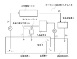
図2には、本発明の第二の実施態様のクーラント液処理システム1B及び工作機械100の構造を示す。
第二の実施態様のクーラント液処理システム1Bでは、ろ過装置2でろ過された処理液を貯留するための処理液槽4と、工作機械100から排出されたスラッジを含むクーラント液を貯留する被処理液槽5を備えている。また、ろ過装置2と処理液槽4との間の流路L2に、検出手段として光学的検知手段3Aが設置されている。
クーラント液は、処理液槽4から流路L4に設置されたポンプP1で工作機械100に供給される。工作機械100で使用されたスラッジを含むクーラント液は、流路L5、前処理装置6、流路L6を介して被処理液槽5に回収される。処理液槽4を備えることにより、ろ過装置2からスラッジが漏出した際に、処理液槽4にスラッジが溜められるため、直ちに工作機械100に大きな粒子などが流入することを防止することができる。
また、光学的検出手段3Aを処理液槽4、流路L4等、ろ過装置2で処理された直後の処理液が他の処理液と合流した後の位置に設置すると、フィルタから漏出したスラッジが処理液槽4中の処理液で希薄化するため、光学的検出手段3Aの感度が低下するという問題がある。よって、光学的検出手段3Aをろ過装置2と処理液槽4との間の流路L2に設置することにより、フィルタから漏出したスラッジが処理液槽4で希薄化する前に検出されるため、光学的検出手段3Aの感度を高めるという効果もある。
なお、光学的検出手段3Aは、ろ過装置2から工作機械100までの間のいずれの位置に設置してもよく、例えば、光学的検出手段3Aを処理液槽4、流路L4等に設置することも可能である。
図3には、本発明の第三の実施態様のクーラント液処理システム1C及び研削盤101の構造を示す。
液温調整機H2は、研削盤101で熱を吸収したクーラント液の温度を低下するための装置である。
また、液面計S4は、処理液槽4の液面が低下した際に、異常を検知し、研削盤101へのクーラント液の供給が停止しないように監視するための装置である。
一方、第三の実施態様のようにすると、被処理液タンク51は、被処理液槽5と比較して底面の面積が小さいためスラッジの堆積する領域が限定されている。また、容量が小さいことから被処理液タンク51の内部全体に強い流れが生じて、スラッジがポンプP5及び/又はポンプP6の方向に移送される。そのため、被処理液タンク51に回収されたスラッジは、被処理液タンク51の底部に堆積せず、ポンプP5及び/又はポンプP6で吸い上げられ、ろ過装置2A及び/又はろ過装置2Bへ供給することができる。
また、フィルタ洗浄やフィルタ交換の際にも、運転を停止することなく、洗浄操作や交換操作を実施することができる。
次に、光学的検知手段3Aにより得られたデータによりスラッジの漏出の有無を判断する(if1)。スラッジの漏出の有無の判断は、特に制限されないが、例えば、目開き10μmのフィルタを用いてろ過処理する場合に、粒子径10μm以上の粒子が1mL当たり10個以上検出されるとスラッジの漏出があると判断する等、目開きより大きな粒子径の粒子の数を設定し、これを超える場合にスラッジの漏出があると判断する。
Claims (3)
- スラッジを含むクーラント液をろ過するためのろ過装置と、前記ろ過装置でろ過された処理液中の粒子を検知する検知手段と、
を備えたことを特徴とする、クーラント液処理システム。 - 前記処理液を貯留する処理液槽を備え、
前記検知手段は、前記ろ過装置と前記処理液槽との間に設置されていることを特徴とする、請求項1に記載のクーラント液処理システム。 - 前記検知手段は、光を用いて粒子を検知する光学的検知手段であることを特徴とする、請求項1又は2に記載のクーラント液処理システム。
Priority Applications (5)
| Application Number | Priority Date | Filing Date | Title |
|---|---|---|---|
| CN201880047575.5A CN111050995A (zh) | 2017-09-14 | 2018-07-03 | 冷却液处理系统 |
| JP2019541914A JP7519740B2 (ja) | 2017-09-14 | 2018-07-03 | クーラント液処理システム |
| EP18856738.2A EP3683013B1 (en) | 2017-09-14 | 2018-07-03 | Coolant liquid processing system |
| KR1020207004994A KR20200053478A (ko) | 2017-09-14 | 2018-07-03 | 쿨런트액처리시스템 |
| US16/786,649 US20200179842A1 (en) | 2017-09-14 | 2020-02-10 | Coolant liquid processing system |
Applications Claiming Priority (2)
| Application Number | Priority Date | Filing Date | Title |
|---|---|---|---|
| JP2017176397 | 2017-09-14 | ||
| JP2017-176397 | 2017-09-14 |
Related Child Applications (1)
| Application Number | Title | Priority Date | Filing Date |
|---|---|---|---|
| US16/786,649 Continuation US20200179842A1 (en) | 2017-09-14 | 2020-02-10 | Coolant liquid processing system |
Publications (1)
| Publication Number | Publication Date |
|---|---|
| WO2019054018A1 true WO2019054018A1 (ja) | 2019-03-21 |
Family
ID=65723595
Family Applications (1)
| Application Number | Title | Priority Date | Filing Date |
|---|---|---|---|
| PCT/JP2018/025187 Ceased WO2019054018A1 (ja) | 2017-09-14 | 2018-07-03 | クーラント液処理システム |
Country Status (7)
| Country | Link |
|---|---|
| US (1) | US20200179842A1 (ja) |
| EP (1) | EP3683013B1 (ja) |
| JP (2) | JP7519740B2 (ja) |
| KR (1) | KR20200053478A (ja) |
| CN (1) | CN111050995A (ja) |
| TW (1) | TWI713888B (ja) |
| WO (1) | WO2019054018A1 (ja) |
Cited By (1)
| Publication number | Priority date | Publication date | Assignee | Title |
|---|---|---|---|---|
| JP2023036702A (ja) * | 2017-09-14 | 2023-03-14 | 住友重機械ファインテック株式会社 | クーラント液処理システム |
Families Citing this family (9)
| Publication number | Priority date | Publication date | Assignee | Title |
|---|---|---|---|---|
| US12179299B2 (en) * | 2018-08-07 | 2024-12-31 | Illinois Tool Works Inc. | Machine tool with recirculating coolant filtration system |
| US20200078894A1 (en) * | 2018-09-07 | 2020-03-12 | Manufacturing Productivity Systems | Coolant filtration system |
| JP7414493B2 (ja) * | 2019-12-03 | 2024-01-16 | ファナック株式会社 | 工作機械 |
| AU2021287162B2 (en) * | 2020-06-11 | 2026-01-08 | Husqvarna Ab | Filter arrangements for industrial dust extractors |
| CN111993152B (zh) * | 2020-09-15 | 2024-10-15 | 宁波市镇海元益机电制造有限公司 | 一种深孔加工钻头中心出液增压控制系统及控制方法 |
| US12403539B2 (en) * | 2020-09-16 | 2025-09-02 | Illinois Tool Works Inc. | Standpipe recirculation systems for material removal machines |
| KR102583098B1 (ko) * | 2021-11-29 | 2023-09-26 | 주식회사 현대에버다임 | 락드릴용 압축기의 내부 윤활장치 |
| KR102730640B1 (ko) * | 2022-09-01 | 2024-11-15 | 주식회사 알차시스템 | 절삭유 회수 모듈이 구비된 절삭 장치 |
| CN116135439A (zh) * | 2023-03-16 | 2023-05-19 | 广东钶锐锶数控技术股份有限公司 | 一种车铣双模组加工设备 |
Citations (3)
| Publication number | Priority date | Publication date | Assignee | Title |
|---|---|---|---|---|
| JP2002052388A (ja) * | 1999-05-27 | 2002-02-19 | Sanyo Electric Co Ltd | 排水の濾過方法 |
| JP2004066425A (ja) | 2002-08-08 | 2004-03-04 | Brother Ind Ltd | 工作機械のクーラントろ過装置 |
| JP2011173190A (ja) * | 2010-02-23 | 2011-09-08 | Iwate Univ | 機械加工システム |
Family Cites Families (26)
| Publication number | Priority date | Publication date | Assignee | Title |
|---|---|---|---|---|
| JPS5129771A (en) * | 1974-09-05 | 1976-03-13 | Honda Engineering | Setsusakuyu no bunrisochi |
| JPS5747205U (ja) * | 1980-09-01 | 1982-03-16 | ||
| DE9407292U1 (de) * | 1994-05-02 | 1994-07-14 | Rietbergwerke GmbH & Co KG, 33397 Rietberg | Vorrichtung zur Pflege von Kühlschmierstoffen |
| JP3680452B2 (ja) * | 1996-11-06 | 2005-08-10 | 富士電機システムズ株式会社 | 膜処理システムの異常検知方法および制御方法 |
| JP3291487B2 (ja) * | 1999-05-27 | 2002-06-10 | 三洋電機株式会社 | 流体の被除去物除去方法 |
| JP3316484B2 (ja) * | 1999-05-27 | 2002-08-19 | 三洋電機株式会社 | 半導体装置の製造方法 |
| US6746309B2 (en) * | 1999-05-27 | 2004-06-08 | Sanyo Electric Co., Ltd. | Method of fabricating a semiconductor device |
| JP3291488B2 (ja) * | 1999-05-27 | 2002-06-10 | 三洋電機株式会社 | 流体の被除去物除去方法 |
| JP2001219338A (ja) * | 2000-02-04 | 2001-08-14 | Toshiba Ceramics Co Ltd | 加工液の汚濁度管理方法および汚濁度管理装置 |
| JP2001343320A (ja) | 2000-05-31 | 2001-12-14 | Mitsubishi Rayon Co Ltd | 分離膜モジュールのリーク検査方法 |
| JP3805270B2 (ja) | 2002-03-14 | 2006-08-02 | 株式会社牧野フライス製作所 | 工作機械の加工液供給装置 |
| KR100475308B1 (ko) | 2003-01-18 | 2005-03-10 | 주식회사 농우바이오 | Cgmmv-저항성 형질전환 박과 작물을 제조하는 방법 |
| JP4033094B2 (ja) | 2003-09-19 | 2008-01-16 | 富士電機システムズ株式会社 | 膜ろ過装置の膜損傷検知方法およびそのための装置 |
| JP4033095B2 (ja) | 2003-09-19 | 2008-01-16 | 富士電機システムズ株式会社 | 膜ろ過装置の膜損傷の検知方法およびそのための装置 |
| JP4518001B2 (ja) | 2005-10-19 | 2010-08-04 | トヨタ自動車株式会社 | 分離方法および分離装置 |
| CN101516570B (zh) | 2006-09-21 | 2012-04-04 | 住友重机械精科技株式会社 | 工作机械用冷却液净化装置 |
| CN101529224B (zh) * | 2006-10-19 | 2012-07-11 | 平田机工株式会社 | 过滤水监视装置及过滤水监视系统 |
| JP2011177810A (ja) | 2010-02-26 | 2011-09-15 | Mitsubishi Heavy Ind Ltd | クーラント浄化装置 |
| JP5011409B2 (ja) * | 2010-02-26 | 2012-08-29 | 日本フローサーブ株式会社 | 環境対応型の固液分離システム |
| JP5732287B2 (ja) * | 2011-03-17 | 2015-06-10 | オルガノ株式会社 | 膜ろ過システム及びろ過膜損傷検知方法 |
| TWM417180U (en) * | 2011-07-26 | 2011-12-01 | Abon Tech Internat Corp | Silicon sludge recycling device from silicon wafer dicing process |
| JP3186254U (ja) * | 2013-07-16 | 2013-09-26 | 株式会社折本設備 | 水道水中の切り屑除去排水装置 |
| JP6328523B2 (ja) * | 2014-08-25 | 2018-05-23 | Dmg森精機株式会社 | クーラント供給装置 |
| CN106624975A (zh) * | 2015-10-28 | 2017-05-10 | 芜湖中驰机床制造有限公司 | 一种带有切削液循环装置的机床 |
| US10400721B2 (en) * | 2015-12-07 | 2019-09-03 | Caterpillar Inc. | Additional fuel filtration on demand |
| JP7519740B2 (ja) * | 2017-09-14 | 2024-07-22 | 住友重機械ファインテック株式会社 | クーラント液処理システム |
-
2018
- 2018-07-03 JP JP2019541914A patent/JP7519740B2/ja active Active
- 2018-07-03 EP EP18856738.2A patent/EP3683013B1/en active Active
- 2018-07-03 WO PCT/JP2018/025187 patent/WO2019054018A1/ja not_active Ceased
- 2018-07-03 KR KR1020207004994A patent/KR20200053478A/ko not_active Ceased
- 2018-07-03 CN CN201880047575.5A patent/CN111050995A/zh active Pending
- 2018-08-30 TW TW107130241A patent/TWI713888B/zh active
-
2020
- 2020-02-10 US US16/786,649 patent/US20200179842A1/en not_active Abandoned
-
2022
- 2022-12-13 JP JP2022198929A patent/JP2023036702A/ja active Pending
Patent Citations (3)
| Publication number | Priority date | Publication date | Assignee | Title |
|---|---|---|---|---|
| JP2002052388A (ja) * | 1999-05-27 | 2002-02-19 | Sanyo Electric Co Ltd | 排水の濾過方法 |
| JP2004066425A (ja) | 2002-08-08 | 2004-03-04 | Brother Ind Ltd | 工作機械のクーラントろ過装置 |
| JP2011173190A (ja) * | 2010-02-23 | 2011-09-08 | Iwate Univ | 機械加工システム |
Cited By (1)
| Publication number | Priority date | Publication date | Assignee | Title |
|---|---|---|---|---|
| JP2023036702A (ja) * | 2017-09-14 | 2023-03-14 | 住友重機械ファインテック株式会社 | クーラント液処理システム |
Also Published As
| Publication number | Publication date |
|---|---|
| EP3683013A4 (en) | 2020-10-21 |
| KR20200053478A (ko) | 2020-05-18 |
| JP7519740B2 (ja) | 2024-07-22 |
| US20200179842A1 (en) | 2020-06-11 |
| EP3683013B1 (en) | 2025-03-19 |
| JPWO2019054018A1 (ja) | 2020-10-15 |
| TWI713888B (zh) | 2020-12-21 |
| CN111050995A (zh) | 2020-04-21 |
| JP2023036702A (ja) | 2023-03-14 |
| EP3683013A1 (en) | 2020-07-22 |
| TW201914753A (zh) | 2019-04-16 |
Similar Documents
| Publication | Publication Date | Title |
|---|---|---|
| WO2019054018A1 (ja) | クーラント液処理システム | |
| JP7235664B2 (ja) | クーラント液処理システム及びフロート式逆止弁 | |
| KR102122995B1 (ko) | 여과 장치 | |
| WO2011042254A1 (de) | Biosensorvorrichtung mit filterüberwachungseinrichtung | |
| US8863763B1 (en) | Sonication cleaning with a particle counter | |
| JP2013006132A (ja) | 圧延クーラントの循環供給設備 | |
| JP2019111503A (ja) | 含油排水の処理方法 | |
| CN204672091U (zh) | 一种剥离液过滤系统 | |
| JP2008080193A (ja) | 濾過システム及び濾過方法 | |
| JPH10177940A (ja) | 薬液供給装置 | |
| CN106078347A (zh) | 一种在对后起升缸进行加工时的切削液循环系统 | |
| JP2013233484A (ja) | 膜モジュールを用いた膜ろ過装置及びろ過膜洗浄方法 | |
| JP4225997B2 (ja) | 濾過装置 | |
| JP2001120966A (ja) | 膜ろ過システム | |
| CN106594006B (zh) | 一种液压油检测净化系统 | |
| JP2016078224A (ja) | 切削液浄化装置 | |
| KR101475805B1 (ko) | 퇴적 방지형 냉각유 탱크 장치 | |
| JP5734038B2 (ja) | 膜ろ過システム及びろ過膜損傷検知方法 | |
| JP2007266211A (ja) | 半導体製造装置及び半導体製造方法 | |
| JP3728512B2 (ja) | ダイオキシン類の除去方法 | |
| JP7712088B2 (ja) | 検体用貯留水槽 | |
| KR101765410B1 (ko) | 청소 기능을 가진 탱크 여과 장치 | |
| TW201946686A (zh) | 過濾裝置以及過濾方法 | |
| KR101753890B1 (ko) | 능동형 싸이클로닉 필터링 카세트 | |
| JP2026055826A (ja) | 貯留装置および液面状態検出方法 |
Legal Events
| Date | Code | Title | Description |
|---|---|---|---|
| 121 | Ep: the epo has been informed by wipo that ep was designated in this application |
Ref document number: 18856738 Country of ref document: EP Kind code of ref document: A1 |
|
| ENP | Entry into the national phase |
Ref document number: 2019541914 Country of ref document: JP Kind code of ref document: A |
|
| ENP | Entry into the national phase |
Ref document number: 20207004994 Country of ref document: KR Kind code of ref document: A |
|
| NENP | Non-entry into the national phase |
Ref country code: DE |
|
| ENP | Entry into the national phase |
Ref document number: 2018856738 Country of ref document: EP Effective date: 20200414 |