WO2019058763A1 - Véhicule de chantier - Google Patents
Véhicule de chantier Download PDFInfo
- Publication number
- WO2019058763A1 WO2019058763A1 PCT/JP2018/028402 JP2018028402W WO2019058763A1 WO 2019058763 A1 WO2019058763 A1 WO 2019058763A1 JP 2018028402 W JP2018028402 W JP 2018028402W WO 2019058763 A1 WO2019058763 A1 WO 2019058763A1
- Authority
- WO
- WIPO (PCT)
- Prior art keywords
- operation lever
- travel
- work
- travel operation
- recess
- Prior art date
- Legal status (The legal status is an assumption and is not a legal conclusion. Google has not performed a legal analysis and makes no representation as to the accuracy of the status listed.)
- Ceased
Links
Images

Classifications
-
- E—FIXED CONSTRUCTIONS
- E02—HYDRAULIC ENGINEERING; FOUNDATIONS; SOIL SHIFTING
- E02F—DREDGING; SOIL-SHIFTING
- E02F9/00—Component parts of dredgers or soil-shifting machines, not restricted to one of the kinds covered by groups E02F3/00 - E02F7/00
- E02F9/20—Drives; Control devices
- E02F9/2004—Control mechanisms, e.g. control levers
-
- E—FIXED CONSTRUCTIONS
- E02—HYDRAULIC ENGINEERING; FOUNDATIONS; SOIL SHIFTING
- E02F—DREDGING; SOIL-SHIFTING
- E02F9/00—Component parts of dredgers or soil-shifting machines, not restricted to one of the kinds covered by groups E02F3/00 - E02F7/00
- E02F9/20—Drives; Control devices
-
- E—FIXED CONSTRUCTIONS
- E02—HYDRAULIC ENGINEERING; FOUNDATIONS; SOIL SHIFTING
- E02F—DREDGING; SOIL-SHIFTING
- E02F9/00—Component parts of dredgers or soil-shifting machines, not restricted to one of the kinds covered by groups E02F3/00 - E02F7/00
- E02F9/20—Drives; Control devices
- E02F9/22—Hydraulic or pneumatic drives
- E02F9/225—Control of steering, e.g. for hydraulic motors driving the vehicle tracks
-
- E—FIXED CONSTRUCTIONS
- E02—HYDRAULIC ENGINEERING; FOUNDATIONS; SOIL SHIFTING
- E02F—DREDGING; SOIL-SHIFTING
- E02F9/00—Component parts of dredgers or soil-shifting machines, not restricted to one of the kinds covered by groups E02F3/00 - E02F7/00
- E02F9/20—Drives; Control devices
- E02F9/22—Hydraulic or pneumatic drives
- E02F9/2253—Controlling the travelling speed of vehicles, e.g. adjusting travelling speed according to implement loads, control of hydrostatic transmission
-
- E—FIXED CONSTRUCTIONS
- E02—HYDRAULIC ENGINEERING; FOUNDATIONS; SOIL SHIFTING
- E02F—DREDGING; SOIL-SHIFTING
- E02F9/00—Component parts of dredgers or soil-shifting machines, not restricted to one of the kinds covered by groups E02F3/00 - E02F7/00
- E02F9/24—Safety devices, e.g. for preventing overload
Definitions
- the present invention mainly relates to a work vehicle provided with a lock mechanism that locks a travel operation lever.
- Patent documents 1 and 2 disclose this kind of work vehicle.
- the traveling working machine of Patent Document 1 includes two traveling operation levers and a fixing mechanism.
- the two travel control levers stand upright on the machine base in front of the driver's seat.
- operation members that rotate integrally with the travel operation lever are provided.
- a locking pin is formed on the actuating member.
- the fixing mechanism comprises a linearly movable fixing piece.
- An engagement recess is formed in the fixed piece, and the travel operation lever is locked by moving the fixed piece linearly and locking the locking pin in the engagement recess.
- the small hydraulic shovel of Patent Document 2 includes two travel operation levers and a travel lock device.
- the two travel operation levers can be respectively rotated about the two cylindrical portions disposed below the floor where the driver's seat is provided.
- a protruding portion which protrudes from the cylindrical portion is formed.
- the travel lock device includes a lock plate and a hydraulic cylinder.
- the lock plate is disposed to be orthogonal to the floor.
- a plurality of grooves are formed in the lock plate.
- the hydraulic cylinder moves the lock plate linearly. By moving the lock plate in a straight line, the projection of the cylindrical portion is inserted into the groove of the lock plate, and the travel operation lever is locked.
- Patent Documents 1 and 2 disclose that the fixing mechanism and the travel lock device can be disposed with space saving. However, Patent Documents 1 and 2 disclose only the configuration in which the fixing piece and the lock plate are linearly moved, and the configuration for realizing the space-saving configuration by other methods is not described.
- the present invention has been made in view of the above circumstances, and its main object is to provide a work vehicle having a lock mechanism for locking a travel operation lever, which has a high degree of freedom in design and can be installed in a space-saving manner.
- a work vehicle having the following configuration. That is, this work vehicle includes a traveling body, two travel operation levers, and a lock mechanism.
- the travel operation lever instructs the travel of the traveling body by tilting it in the front-rear direction.
- the lock mechanism can restrict tilting of the two travel operation levers in the front-rear direction.
- the lock mechanism includes a drive unit, a transmission unit, and a lock plate.
- the drive unit generates a driving force.
- the transmission unit transmits the driving force generated by the driving unit.
- the lock plate is a plate-like member, a thickness direction of which is parallel to a longitudinal direction of the travel operation lever at the time of neutral, and a first recess and a second recess are formed.
- the lock plate is rotated about a direction parallel to the longitudinal direction of the travel operation lever by the drive force transmitted by the transmission unit as a rotation center, thereby forming two lock plates in the first recess and the second recess.
- a lock position at which tilting of the travel operation lever in the back and forth direction is restricted by the entry of the travel operation lever, and a release position in which the two travel operation levers are respectively separated from the first recess and the second recess The position can be switched between and.
- the traveling operation lever itself instead of another member attached to the base of the traveling operation lever, the range in which the lock mechanism can be attached becomes wider, and the degree of freedom in design can be improved. Furthermore, the structure can be simplified because no separate member attached to the travel control lever is required. Further, the thickness direction of the lock plate and the longitudinal direction at the neutral time of the travel operation lever are parallel, and the rotation locus of the lock plate can be reduced by rotating the longitudinal direction as a rotation center. Therefore, the space required to provide the locking mechanism can be reduced.
- the drive unit has a movable portion, and the movable portion generates a driving force by linear movement.
- the transmission unit converts the linear motion of the movable portion into rotational motion centering around a direction parallel to the longitudinal direction of the travel operation lever in the neutral direction, and rotates the lock plate.
- the direction in which the movable portion linearly moves is parallel to the longitudinal direction of the travel operation lever when it is neutral.
- the direction in which the movable portion linearly moves becomes parallel to both the longitudinal direction of the travel operation lever in the neutral direction and the rotation center of the lock plate, so the configuration of the transmission portion is simplified or the size of the transmission portion is reduced. It becomes possible to make it small.
- the work vehicle includes a work operation lever and a console box.
- the work operation levers are respectively disposed on the left and right of the driver's seat, and can operate at least the work device.
- the work operation lever is attached to the console box, and can be integrally rotated with the work operation lever with the left and right direction as a rotation center.
- the regulation of the inclination of the two travel operation levers by the lock mechanism is started.
- the travel operation lever can be locked at the timing (early timing) at which the work operation lever and the console box start to rotate backward.
- the effect of the present invention that the lock mechanism can be disposed with space saving is made more effective. It can be demonstrated.
- this work vehicle includes a driver's seat and a floor.
- the driver's seat is for the operator to sit.
- the floor is for the operator sitting on the driver's seat to put a foot.
- the work vehicle is equipped with a control box.
- the control box is provided so as to project upward from a portion of the floor located in front of the driver's seat, and the directional control valve unit comprising a plurality of directional control valves capable of switching the hydraulic oil delivery direction is Will be placed.
- the two travel control levers are provided on the control box.
- the locking mechanism is disposed inside the steering box.
- the direction switching valve unit is disposed inside the control box, the space in the control box can be easily limited, so that the effect of the present invention that the lock mechanism can be arranged with less space can be exhibited more effectively. Further, since the configuration in which the control box is provided in front of the driver's seat is often adopted mainly in a small work vehicle, also in this point, the effect of the present invention can be more effectively exhibited.
- FIG. 8 is a side view showing a change in the position of each member when the lock mechanism releases the lock of the travel operation lever.
- the top view which shows the change of the position of each member at the time of a lock mechanism unlocking a run operation lever.
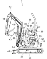
- FIG. 1 is a perspective view showing an overall configuration of a swing working vehicle 1 according to an embodiment of the present invention.
- FIG. 2 is a side view of the turning working vehicle 1.
- the turning work vehicle (working vehicle) 1 of the present embodiment shown in FIGS. 1 and 2 includes a lower traveling body (traveling body) 11 and an upper revolving superstructure 12.
- the lower traveling body 11 includes a crawler traveling device 21 disposed in a pair of right and left, and a hydraulic motor (not shown) that drives the crawler traveling device 21.
- the lower traveling body 11 can drive the left and right crawler traveling devices 21 individually at various directions and speeds, and can perform various travelings such as straight traveling forward or backward and steering.
- the upper swing body 12 includes a swing frame 31, a bonnet 32, an engine 33, a hydraulic pump unit 34, a work device 13, and a control unit 35.
- the swing frame 31 is disposed above the lower traveling body 11 and supported by the lower traveling body 11 so as to be rotatable about an axis perpendicular to the horizontal plane.
- the swing frame 31 can be rotated relative to the lower traveling body 11 by the drive of a swing motor (not shown).
- the bonnet 32 is disposed at the rear of the swing frame 31, and the engine 33 is disposed inside.
- the engine 33 is configured as, for example, a diesel engine.
- the hydraulic pump unit 34 is driven by the engine 33 and generates hydraulic pressure necessary for traveling and work of the swing working vehicle 1.
- the working device 13 includes a boom 41, an arm 42, a bucket 43, and a blade (drain plate) 44.
- Hydraulic cylinders are connected to the boom 41, the arm 42, the bucket 43 and the blade 44, respectively. By expanding and contracting these hydraulic cylinders by the hydraulic pressure generated by the hydraulic pump unit 34, the boom 41 and the arm 42 are pivoted to change the position, work such as digging with the bucket 43, or the blade 44 can be turned up and down.
- the control unit 35 includes various operation members disposed around a driver's seat 39 for the operator to sit on.
- the operation members are mainly disposed in the control box 50 and the console box 60.
- front, rear, left and right are defined in a direction viewed from the operator sitting on the driver's seat 39 in a state where the front of the lower traveling body 11 and the upper swing body 12 are aligned.
- the control box 50 is provided in front of the driver's seat 39 so as to rise upward from the floor 25 on which the operator seated on the driver's seat 39 rests.
- the control box 50 is provided with a travel operation lever 36 for instructing the traveling of the turning work vehicle 1 and a blade operation lever 37 for instructing elevation and lowering of the blade 44.
- the travel control lever 36 is provided to extend upward (in detail, obliquely rearward and upward) from the steering box 50.
- the travel operation lever 36 is disposed in a pair on the left and right, and by operating the travel operation lever 36 on the left side, an instruction can be given to the crawler travel device 21 on the left side.
- An instruction can be issued to the crawler traveling device 21 on the right side.
- the crawler operating device 36 can be driven in the forward direction by tilting the traveling operation lever 36 forward, and the crawler operating device 36 can be driven in the reverse direction by tilting the traveling operation lever 36 backward. By positioning the travel operation lever 36 in the neutral position, the crawler travel device 21 can be stopped.
- a direction switching valve unit 38 is disposed inside the control box 50.
- the direction switching valve unit 38 includes a plurality of direction switching valves for switching the drive / stop of the hydraulic actuator provided in the turning work vehicle 1 or the like.
- the direction switching valve is configured to include a spool, and the crawler traveling device 21, the swing motor, the working device 13 and the like are driven by displacing the spool according to the operation of the operation member.
- the console boxes 60 are arranged in a pair on the left and right so as to sandwich the driver's seat 39.
- the driver's seat 39 and the console box 60 are disposed on the upper surface of the bonnet 32 provided in the upper swing body 12.
- the left and right console boxes 60 have symmetrical configurations, and the configurations are substantially the same.
- a work operation lever 61 and a lock lever 62 are provided in the left and right console boxes 60, respectively.
- the console box 60 is rotatably supported around a left and right direction with respect to a bracket (not shown) fixed to the upper surface of the bonnet 32. Further, since the operation control lever 61 and the lock lever 62 are attached to the console box 60, the operation control lever 61 and the lock lever 62 also rotate integrally with the console box 60. Thereby, as shown by a two-dot chain line in FIG. 2, the posture of the console box 60 can be changed between the normal posture shown by a solid line and the retracted posture shown by a two-dot chain line.
- the operator who has got on the swing working vehicle 1 operates the work operation lever 61 with the console box 60 in the normal posture.
- the console box 60 can be retracted so as not to interfere with the body of the operator by setting the console box 60 in the retracted position.
- the work operation lever 61 is provided to extend upward (in detail, obliquely upward in the front direction) from the upper portion of the console box 60.
- the operation control lever 61 is a lever for instructing the swing of the upper swing body 12 and the drive of the boom 41, the arm 42, and the bucket 43.
- the lock lever 62 When the console box 60 is in the normal posture, the lock lever 62 is provided to extend obliquely upward and forward from the front of the console box 60.
- the rotation of the console box 60 is restricted by the restriction mechanism (not shown) in the normal posture and the retracted posture. By rotating the lock lever 62, the restriction of the restriction mechanism can be released, and the console box 60 can be rotated.
- the console box 60 is provided with contact sensors and contact members (not shown), and when the console box 60 is in the normal posture, the contact members contact the contact sensors. In addition, at the timing when the console box 60 in the normal posture starts to rotate backward, the contact member separates from the contact sensor. When the contact member is not in contact with the contact sensor, the supply of hydraulic fluid based on the operation of the work operation lever 61 is cut off by closing the solenoid valve etc., so the operation of the work operation lever 61 is invalidated. It becomes. Furthermore, the travel control lever 36 is locked by the operation of the lock mechanism 70 described below.
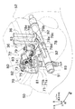
- FIG. 3 is a perspective view showing the configuration of the lock mechanism 70.
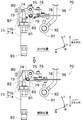
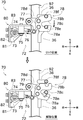
- FIG. 4 and FIG.5 is a side view and a top view which show the change of the position of each member when the lock mechanism 70 unlocks the traveling control lever 36.
- expressions describing directions such as parallel or perpendicular are not limited to the configuration in which the state exactly as stated above is strictly established, and for example, a configuration in which a difference of about several degrees has occurred (substantially parallel or Approximately vertical) shall also be included.
- an inclined surface 52 is formed at the top and the rear of the steering box 50.
- the inclined surface 52 is a surface inclined so as to approach upward as approaching forward.
- the inclined surface 52 is provided with a notification lamp for notifying of an abnormality or the like of the battery, a counter for displaying the total work time, and the like.
- two lever insertion holes 53 are formed in the lateral direction at the center of the inclined surface 52 in the lateral direction.
- the two travel control levers 36 are respectively inserted into these two lever insertion holes 53. Accordingly, the travel control lever 36 is disposed to penetrate the exterior member (housing) of the control box 50.
- the rotation shaft portion 91 is an elongated cylindrical member, and is arranged such that the axial direction (longitudinal direction) is parallel to the left and right direction.
- the rotating cylinder 92 is a cylindrical member attached so as to be rotatable relative to the rotating shaft 91.
- a plurality of rotary cylinder portions 92 are arranged in the axial direction of the rotary shaft portion 91.
- the two travel operation levers 36 are welded to different rotary cylinder portions 92, respectively. As a result, by operating the travel operation lever 36, only the corresponding rotary cylinder 92 is rotated.
- a power transmission member (not shown) is attached to the rotary cylinder 92, and the power accompanying the rotation of the rotary cylinder 92 is transmitted to the direction switching valve unit 38 to displace the above-described spool.
- the travel control lever 36 is curved at the inner side relative to the control box 50, but the portion occupying much of the travel control lever 36 (the portion outside the control box 50) is linear. . Therefore, when referring to "longitudinal direction of travel control lever 36" or the like, it means the longitudinal direction of the portion (portion outside the steering box 50) which occupies most of the travel operation lever 36. Further, in the following description, the longitudinal direction of the travel operation lever 36 when the travel operation lever 36 is in the neutral state (a state in which the stop of the crawler travel device 21 is instructed) is referred to as "lever longitudinal direction". Further, as described above, the longitudinal direction of the lever is inclined with respect to the vertical direction, but one side closer to the upper side in one side of the longitudinal direction of the lever may be referred to as "upper side in the longitudinal direction of the lever" or the like.
- the lock mechanism 70 is a mechanism for locking the travel operation lever 36 (by preventing the operation by the travel operation lever 36 from being performed) by restricting the inclination of the travel operation lever 36 in the front-rear direction.
- the lock mechanism 70 includes a hydraulic cylinder (drive unit) 71, a transmission unit 72, and a lock plate 78. Further, each part constituting the lock mechanism 70 is supported by the stay 80.
- the stay 80 includes a cylinder support portion 81 for supporting the hydraulic cylinder 71, a frame attachment portion 82 attached to a frame constituting the control box 50, and a rotation shaft for supporting a first rotation shaft 75 and a second rotation shaft 79 described later. And a support portion 83.
- the hydraulic cylinder 71 is a drive unit that generates a driving force by being supplied with hydraulic oil from one end via the hydraulic hose 93.
- the hydraulic cylinder 71 is an elongated member, and includes a main body portion 71a and a movable portion 71b.
- the longitudinal direction of the main body portion 71a and the movable portion 71b is parallel to the longitudinal direction of the lever.
- the movable portion 71b is provided at the other end portion (upper end portion in the longitudinal direction of the lever) of the main body portion 71a.
- the movable portion 71 b is configured to be movable linearly with respect to the main body portion 71 a in the lever longitudinal direction.
- the hydraulic cylinder 71 is provided with a spring (biasing member) (not shown), and in a state where the hydraulic oil is not supplied to the hydraulic cylinder 71, the main body 71a is under the lever longitudinal direction by the biasing force of the spring. Located on the side. Since the hydraulic oil is supplied to the hydraulic cylinder 71, the movable portion 71b is pressed by a force stronger than the biasing force of the spring and moves upward in the lever longitudinal direction. While the contact member is in contact with the contact sensor of the console box 60, the hydraulic oil is supplied to the hydraulic cylinder 71. On the other hand, the supply of the hydraulic fluid is stopped when the contact member is separated from the contact sensor of the console box 60 (that is, when the console box 60 starts to rotate backward from the normal posture).
- a spring biasing member
- the transmission portion 72 transmits the driving force (linear motion of the movable portion 71b in the longitudinal direction of the lever) generated by the hydraulic cylinder 71 to rotate the lock plate 78 about the longitudinal direction of the lever.
- the transmission unit 72 includes a link arm 73, a link plate 74, a first rotation shaft 75, a ball joint 76, and a rotation plate 77.
- the link arm 73 is fixed to the movable portion 71 b and configured to move integrally with the movable portion 71 b.
- the longitudinal direction of the link arm 73 is parallel to the longitudinal direction of the lever.
- One end (lower end in the lever longitudinal direction) of the link arm 73 is fixed to the movable portion 71 b, and the other end (upper end in the longitudinal direction of the lever) of the link arm 73 is rotatably attached to the link plate 74 There is.
- the link plate 74 is disposed such that the thickness direction is parallel to the left and right direction.
- the link plate 74 is rotatably supported by the rotation shaft support 83 with the first rotation shaft 75 as a rotation axis (with the left and right direction as the rotation center).
- the link arm 73 is rotatably attached to the front end (one end) of the link plate 74 as described above, and the ball joint 76 is rotatably attached to the rear end (the other end) of the link plate 74 It is done.
- the link plate 74 is rotated by the hydraulic oil supplied to the hydraulic cylinder 71 and the movable portion 71b linearly moving upward in the longitudinal direction of the lever. Thereby, the ball joint 76 attached to the link plate 74 linearly moves substantially forward.
- the ball joint 76 is rotatably attached to the link plate 74 at the rear end portion (one end portion) so as to be rotatable in the left-right direction. Further, the ball joint 76 is attached at the front end portion (one end portion) to the rotary plate 77 so as to be rotatable about the longitudinal direction of the lever. With this configuration, the ball joint 76 can transmit power between two members (link plate 74 and rotating plate 77) having different directions of rotation axes.
- the rotary plate 77 is disposed such that the thickness direction is parallel to the lever longitudinal direction.
- the rotary plate 77 is supported by the rotary shaft support 83 so as to be rotatable with the second rotary shaft 79 as a rotary shaft (with the lever longitudinal direction as the center of rotation). Since the lock plate 78 is fixed to the rotary plate 77, the rotary plate 77 and the lock plate 78 rotate integrally.
- the rotary plate 77 and the lock plate 78 rotate in the same plane because the thickness direction and the rotation center are parallel, and therefore the rotation locus becomes smaller. Further, since the center of rotation and the lever longitudinal direction are parallel to each other, the lock plate 78 approaches the travel operation lever 36 at a substantially shortest distance, so that the rotation locus also becomes smaller at this point. Therefore, the space-saving lock mechanism 70 can be realized. Furthermore, since the directional control valve unit 38 is disposed in the control box 50 and hydraulic fluid is supplied from the directional control valve unit 38 to the hydraulic cylinder 71, the hydraulic hose 93 can be shortened.
- the lock plate 78 is formed with a first arm 78 a and a second arm 78 b extending away from the second rotation shaft 79.
- a space between the first arm 78a and the second arm 78b is referred to as a space 78c.
- the lock plate 78 of the present embodiment includes the connection portion 78d for connecting the first arm 78a and the second arm 78b, the first arm 78a and the second arm 78b may be separate members. .
- the left travel control lever 36 is located in a space 78c between the first arm 78a and the second arm 78b. Further, the travel operation lever 36 on the right side is located on the right side of the second arm 78b.
- a first recess 78e is formed on the right side of the first arm 78a (the side of the second arm 78b, the side of the space 78c, the inner side of the lock plate 78, the side of the travel operation lever 36 on the left side).
- a second recess 78f is formed on the right side of the second arm 78b (the opposite side of the first arm 78a, the opposite side of the air gap 78c, the outer side of the lock plate 78, and the travel operation lever 36 on the right side).
- the lock plate 78 can be rotated between the lock position and the release position.
- the lock plate 78 switches from the lock position to the release position by rotating clockwise in top view.
- the lock plate 78 when hydraulic oil is not supplied to the hydraulic cylinder 71, the lock plate 78 is positioned at the lock position.
- the travel operation lever 36 enters the first recess 78 e and the second recess 78 f, whereby the tilt of the travel operation lever 36 in the front-rear direction is restricted. Therefore, for example, the traveling control lever 36 can be locked when the operator gets on / off.
- the lock plate 78 is located at the release position.
- the travel operation lever 36 is located outside the first recess 78 e and the second recess 78 f.
- the left travel control lever 36 can be tilted in the front-rear direction by the air gap 78c. Therefore, the length of the air gap 78c is determined so as not to contact the lock plate 78 even when the travel operation lever 36 is tilted to the frontmost side. Further, since the right travel control lever 36 does not overlap with the lock plate 78 in the left-right direction, it can be tilted in the front-rear direction.
- the turning work vehicle 1 of the present embodiment includes the lower traveling body 11, the two traveling operation levers 36, and the lock mechanism 70.
- the traveling operation lever 36 instructs the traveling of the lower traveling body 11 by tilting it in the front-rear direction.
- the lock mechanism 70 can restrict tilting of the two travel operation levers 36 in the front-rear direction.
- the lock mechanism 70 includes a hydraulic cylinder 71, a transmission unit 72, and a lock plate 78.
- the hydraulic cylinder 71 generates a driving force.
- the transmission unit 72 transmits the driving force generated by the hydraulic cylinder 71.
- the lock plate 78 is a plate-like member, the thickness direction of which is parallel to the longitudinal direction of the travel operation lever 36 in the neutral state, and the first recess 78 e and the second recess 78 f are formed.
- the lock plate 78 rotates about the direction parallel to the longitudinal direction of the travel operation lever 36 in the neutral direction by the driving force transmitted by the transmission unit 72 as a rotation center, thereby forming two lock plates in the first recess 78 e and the second recess 78 f.
- the position can be switched between.
- the traveling operation lever 36 itself instead of another member attached to the base of the traveling operation lever 36, the range in which the lock mechanism 70 can be attached is expanded, so that the degree of freedom in design can be improved. it can. Furthermore, the structure can be simplified because no separate member attached to the travel operation lever 36 is required. Further, the thickness direction of the lock plate 78 and the longitudinal direction at the neutral time of the travel operation lever 36 are parallel, and the rotation locus of the lock plate 78 can be made smaller by rotating the longitudinal direction as a rotation center. Therefore, the space required to provide the locking mechanism 70 can be reduced.
- the hydraulic cylinder 71 has a movable portion 71 b, and generates a driving force by linear movement of the movable portion 71 b.
- the transmission unit 72 converts the linear motion of the movable portion 71 b into a rotational motion centering around a direction parallel to the longitudinal direction of the travel operation lever 36 at the neutral time, and rotates the lock plate 78.
- the direction in which the movable portion 71b linearly moves is parallel to the longitudinal direction of the travel operation lever 36 when it is neutral.
- the direction in which the movable portion 71b linearly moves is parallel to both the longitudinal direction of the travel operation lever 36 in the neutral state and the rotation center of the lock plate 78, so the configuration of the transmission portion 72 can be simplified or the transmission portion It is possible to reduce the size of 72.
- the turning work vehicle 1 of the present embodiment includes a work operation lever 61 and a console box 60.
- the work operation levers 61 are respectively disposed on the left and right of the driver's seat 39 and can operate at least the work device 13.
- a work operation lever 61 is attached to the console box 60, and can be integrally rotated with the work operation lever 61 with the left and right direction as the center of rotation.
- the travel operation lever 36 can be locked at the timing (early timing) at which the work operation lever 61 and the console box 60 start rotating backward.
- the lock mechanism 70 can be disposed with a space saving. The effects of the present invention can be exhibited more effectively.
- the turning work vehicle 1 includes a driver's seat 39 and a floor.
- the driver's seat 39 is for the operator to sit.
- the floor is for the operator sitting on the driver's seat 39 to place his or her foot.
- the swing working vehicle 1 includes a control box 50.
- the control box 50 is provided to project upward from a portion of the floor located in front of the driver's seat 39, and is a directional control valve unit 38 configured of a plurality of directional control valves capable of switching the delivery direction of hydraulic fluid. Is placed inside.
- Two travel control levers 36 are provided on the control box 50.
- a locking mechanism 70 is disposed inside the steering box 50.
- the direction switching valve unit 38 is disposed inside the steering box 50, the space in the steering box 50 is easily limited, so the space saving effect of the present invention that the lock mechanism 70 can be disposed can be exhibited more effectively. be able to.
- the configuration provided with the control box 50 in front of the driver's seat 39 is often adopted in the small-sized turning work vehicle 1 as in this embodiment, the effect of the present invention is more effectively exhibited also in this respect. It can be done.
- the direction in which the lock plate 78 is rotated to unlock the travel control lever 36 may be opposite to that in the above embodiment (counterclockwise in top view). Further, the direction of the force generated by the hydraulic cylinder 71 may not be parallel to the lever longitudinal direction, and may be perpendicular to the lever longitudinal direction, for example.
- the console box 60 is integrally rotated backward with the work operation lever 61 to invalidate the instruction to the work device 13 or the like by the work operation lever 61.
- another lever may be provided (a configuration in which the console box 60 is not rotated at the time of getting on and off of the operator) for invalidating an instruction to the work device or the like by the work operation lever 61.
- the hydraulic cylinder 71 has been described as an example of the drive portion of the lock mechanism, but drive portions having other configurations can also be used.
- it may be a cylinder that generates a driving force by supplying a fluid (such as air) other than hydraulic oil, or a driving unit that generates a driving force according to the presence or absence of an electrical signal or current ) May be.
Landscapes
- Engineering & Computer Science (AREA)
- Mining & Mineral Resources (AREA)
- Civil Engineering (AREA)
- General Engineering & Computer Science (AREA)
- Structural Engineering (AREA)
- Operation Control Of Excavators (AREA)
- Component Parts Of Construction Machinery (AREA)
- Mechanical Control Devices (AREA)
- Non-Deflectable Wheels, Steering Of Trailers, Or Other Steering (AREA)
Abstract
Priority Applications (4)
| Application Number | Priority Date | Filing Date | Title |
|---|---|---|---|
| BR112020003686-2A BR112020003686A2 (pt) | 2017-09-20 | 2018-07-30 | veículo de trabalho |
| KR1020207033494A KR102482320B1 (ko) | 2017-09-20 | 2018-07-30 | 작업 차량 |
| KR1020197022957A KR102187012B1 (ko) | 2017-09-20 | 2018-07-30 | 작업 차량 |
| EP18858555.8A EP3686355B1 (fr) | 2017-09-20 | 2018-07-30 | Pelle hydraulique |
Applications Claiming Priority (2)
| Application Number | Priority Date | Filing Date | Title |
|---|---|---|---|
| JP2017-180258 | 2017-09-20 | ||
| JP2017180258A JP6735258B2 (ja) | 2017-09-20 | 2017-09-20 | 作業車両 |
Publications (1)
| Publication Number | Publication Date |
|---|---|
| WO2019058763A1 true WO2019058763A1 (fr) | 2019-03-28 |
Family
ID=65810218
Family Applications (1)
| Application Number | Title | Priority Date | Filing Date |
|---|---|---|---|
| PCT/JP2018/028402 Ceased WO2019058763A1 (fr) | 2017-09-20 | 2018-07-30 | Véhicule de chantier |
Country Status (5)
| Country | Link |
|---|---|
| EP (1) | EP3686355B1 (fr) |
| JP (1) | JP6735258B2 (fr) |
| KR (2) | KR102187012B1 (fr) |
| BR (1) | BR112020003686A2 (fr) |
| WO (1) | WO2019058763A1 (fr) |
Families Citing this family (1)
| Publication number | Priority date | Publication date | Assignee | Title |
|---|---|---|---|---|
| JP7652669B2 (ja) | 2021-09-16 | 2025-03-27 | ヤンマーホールディングス株式会社 | ロック機構 |
Citations (5)
| Publication number | Priority date | Publication date | Assignee | Title |
|---|---|---|---|---|
| JPH04203031A (ja) * | 1990-11-30 | 1992-07-23 | Hitachi Constr Mach Co Ltd | レバーロック装置 |
| JPH08284212A (ja) | 1995-04-13 | 1996-10-29 | Shin Caterpillar Mitsubishi Ltd | 走行作業機の走行レバー固定装置 |
| JPH11180677A (ja) * | 1997-12-24 | 1999-07-06 | Furukawa Co Ltd | クローラクレーンの安全装置 |
| JP2000319939A (ja) * | 1999-05-13 | 2000-11-21 | Sumitomo Constr Mach Co Ltd | 建設機械の走行レバーロック装置 |
| JP2016141934A (ja) | 2015-01-29 | 2016-08-08 | 日立建機株式会社 | 小型油圧ショベル |
Family Cites Families (9)
| Publication number | Priority date | Publication date | Assignee | Title |
|---|---|---|---|---|
| JPS5828043Y2 (ja) * | 1977-10-07 | 1983-06-18 | 株式会社クボタ | 作業車のア−ム下降阻止構造 |
| JPS5943566U (ja) * | 1982-09-14 | 1984-03-22 | 日立建機株式会社 | 建設機械の走行レバ−装置 |
| JPH0327099Y2 (fr) * | 1984-09-10 | 1991-06-12 | ||
| JP2770994B2 (ja) * | 1989-09-30 | 1998-07-02 | 井関農機株式会社 | 小型ショベルカーに於ける油圧操作レバーのロック装置 |
| JP3005589B2 (ja) * | 1991-10-15 | 2000-01-31 | 井関農機株式会社 | 操作レバーのロック装置 |
| JP2625306B2 (ja) * | 1992-01-14 | 1997-07-02 | 株式会社豊田自動織機製作所 | 荷役制御用リミットスイッチの支持装置 |
| JP2007276942A (ja) | 2006-04-05 | 2007-10-25 | Toyota Industries Corp | 同時操作制限機構及びフォークリフト |
| JP5162019B1 (ja) * | 2011-10-28 | 2013-03-13 | 株式会社小松製作所 | 操作レバーロック装置 |
| GB2527334A (en) * | 2014-06-18 | 2015-12-23 | Bamford Excavators Ltd | Working machine joystick assembly |
-
2017
- 2017-09-20 JP JP2017180258A patent/JP6735258B2/ja active Active
-
2018
- 2018-07-30 KR KR1020197022957A patent/KR102187012B1/ko active Active
- 2018-07-30 KR KR1020207033494A patent/KR102482320B1/ko active Active
- 2018-07-30 EP EP18858555.8A patent/EP3686355B1/fr active Active
- 2018-07-30 BR BR112020003686-2A patent/BR112020003686A2/pt not_active Application Discontinuation
- 2018-07-30 WO PCT/JP2018/028402 patent/WO2019058763A1/fr not_active Ceased
Patent Citations (5)
| Publication number | Priority date | Publication date | Assignee | Title |
|---|---|---|---|---|
| JPH04203031A (ja) * | 1990-11-30 | 1992-07-23 | Hitachi Constr Mach Co Ltd | レバーロック装置 |
| JPH08284212A (ja) | 1995-04-13 | 1996-10-29 | Shin Caterpillar Mitsubishi Ltd | 走行作業機の走行レバー固定装置 |
| JPH11180677A (ja) * | 1997-12-24 | 1999-07-06 | Furukawa Co Ltd | クローラクレーンの安全装置 |
| JP2000319939A (ja) * | 1999-05-13 | 2000-11-21 | Sumitomo Constr Mach Co Ltd | 建設機械の走行レバーロック装置 |
| JP2016141934A (ja) | 2015-01-29 | 2016-08-08 | 日立建機株式会社 | 小型油圧ショベル |
Non-Patent Citations (1)
| Title |
|---|
| See also references of EP3686355A4 |
Also Published As
| Publication number | Publication date |
|---|---|
| KR20200135557A (ko) | 2020-12-02 |
| JP2019056216A (ja) | 2019-04-11 |
| KR102187012B1 (ko) | 2020-12-04 |
| EP3686355A1 (fr) | 2020-07-29 |
| JP6735258B2 (ja) | 2020-08-05 |
| EP3686355B1 (fr) | 2023-06-28 |
| BR112020003686A2 (pt) | 2020-09-01 |
| KR20190105037A (ko) | 2019-09-11 |
| KR102482320B1 (ko) | 2022-12-27 |
| EP3686355A4 (fr) | 2021-06-16 |
Similar Documents
| Publication | Publication Date | Title |
|---|---|---|
| JP3725769B2 (ja) | ハンドガイドローラ | |
| CN107077162B (zh) | 作业车辆 | |
| US9534354B2 (en) | Construction machine | |
| CN117242226A (zh) | 杆装置以及作业机 | |
| JP6735258B2 (ja) | 作業車両 | |
| JP6944025B2 (ja) | 作業車両 | |
| JP4675850B2 (ja) | 作業機械 | |
| JP7008526B2 (ja) | 作業車両 | |
| JP6739413B2 (ja) | 作業車両 | |
| JP6770013B2 (ja) | クランプアームを備えた解体機械 | |
| JP2009030248A (ja) | 旋回作業車の運転操作部 | |
| JP2003129477A (ja) | 建設機械の作業用アタッチメント格納装置 | |
| WO2024004701A1 (fr) | Dispositif de levier et engin de chantier le comprenant | |
| JP7652669B2 (ja) | ロック機構 | |
| JP6894334B2 (ja) | 作業車両 | |
| JP2007118795A (ja) | 建設機械 | |
| JP3561442B2 (ja) | 作業車両の操縦装置 | |
| JP2010275735A (ja) | 建設機械 | |
| JP7094848B2 (ja) | 作業用車両 | |
| JP7080567B2 (ja) | 作業用車両 | |
| JP2019138005A (ja) | 作業車両 | |
| JP7091206B2 (ja) | 作業用車両 | |
| JP2025130534A (ja) | 操作機構及び作業車 | |
| JP2019167688A (ja) | 油圧ショベル | |
| WO2019186710A1 (fr) | Véhicule de chantier |
Legal Events
| Date | Code | Title | Description |
|---|---|---|---|
| 121 | Ep: the epo has been informed by wipo that ep was designated in this application |
Ref document number: 18858555 Country of ref document: EP Kind code of ref document: A1 |
|
| ENP | Entry into the national phase |
Ref document number: 20197022957 Country of ref document: KR Kind code of ref document: A |
|
| REG | Reference to national code |
Ref country code: BR Ref legal event code: B01A Ref document number: 112020003686 Country of ref document: BR |
|
| NENP | Non-entry into the national phase |
Ref country code: DE |
|
| ENP | Entry into the national phase |
Ref document number: 2018858555 Country of ref document: EP Effective date: 20200420 |
|
| ENP | Entry into the national phase |
Ref document number: 112020003686 Country of ref document: BR Kind code of ref document: A2 Effective date: 20200221 |