WO2019059181A1 - 脱硫装置 - Google Patents
脱硫装置 Download PDFInfo
- Publication number
- WO2019059181A1 WO2019059181A1 PCT/JP2018/034496 JP2018034496W WO2019059181A1 WO 2019059181 A1 WO2019059181 A1 WO 2019059181A1 JP 2018034496 W JP2018034496 W JP 2018034496W WO 2019059181 A1 WO2019059181 A1 WO 2019059181A1
- Authority
- WO
- WIPO (PCT)
- Prior art keywords
- pipe
- absorption tower
- flange
- spray
- spray pipe
- Prior art date
- Legal status (The legal status is an assumption and is not a legal conclusion. Google has not performed a legal analysis and makes no representation as to the accuracy of the status listed.)
- Ceased
Links
Images






Classifications
-
- B—PERFORMING OPERATIONS; TRANSPORTING
- B01—PHYSICAL OR CHEMICAL PROCESSES OR APPARATUS IN GENERAL
- B01D—SEPARATION
- B01D53/00—Separation of gases or vapours; Recovering vapours of volatile solvents from gases; Chemical or biological purification of waste gases, e.g. engine exhaust gases, smoke, fumes, flue gases, aerosols
- B01D53/34—Chemical or biological purification of waste gases
- B01D53/46—Removing components of defined structure
- B01D53/48—Sulfur compounds
- B01D53/50—Sulfur oxides
- B01D53/501—Sulfur oxides by treating the gases with a solution or a suspension of an alkali or earth-alkali or ammonium compound
- B01D53/504—Sulfur oxides by treating the gases with a solution or a suspension of an alkali or earth-alkali or ammonium compound characterised by a specific device
-
- B—PERFORMING OPERATIONS; TRANSPORTING
- B01—PHYSICAL OR CHEMICAL PROCESSES OR APPARATUS IN GENERAL
- B01D—SEPARATION
- B01D53/00—Separation of gases or vapours; Recovering vapours of volatile solvents from gases; Chemical or biological purification of waste gases, e.g. engine exhaust gases, smoke, fumes, flue gases, aerosols
- B01D53/34—Chemical or biological purification of waste gases
- B01D53/46—Removing components of defined structure
- B01D53/48—Sulfur compounds
- B01D53/50—Sulfur oxides
-
- B—PERFORMING OPERATIONS; TRANSPORTING
- B01—PHYSICAL OR CHEMICAL PROCESSES OR APPARATUS IN GENERAL
- B01D—SEPARATION
- B01D53/00—Separation of gases or vapours; Recovering vapours of volatile solvents from gases; Chemical or biological purification of waste gases, e.g. engine exhaust gases, smoke, fumes, flue gases, aerosols
- B01D53/34—Chemical or biological purification of waste gases
- B01D53/46—Removing components of defined structure
- B01D53/48—Sulfur compounds
- B01D53/50—Sulfur oxides
- B01D53/501—Sulfur oxides by treating the gases with a solution or a suspension of an alkali or earth-alkali or ammonium compound
- B01D53/505—Sulfur oxides by treating the gases with a solution or a suspension of an alkali or earth-alkali or ammonium compound in a spray drying process
-
- B—PERFORMING OPERATIONS; TRANSPORTING
- B01—PHYSICAL OR CHEMICAL PROCESSES OR APPARATUS IN GENERAL
- B01D—SEPARATION
- B01D53/00—Separation of gases or vapours; Recovering vapours of volatile solvents from gases; Chemical or biological purification of waste gases, e.g. engine exhaust gases, smoke, fumes, flue gases, aerosols
- B01D53/34—Chemical or biological purification of waste gases
- B01D53/74—General processes for purification of waste gases; Apparatus or devices specially adapted therefor
- B01D53/77—Liquid phase processes
- B01D53/78—Liquid phase processes with gas-liquid contact
-
- B—PERFORMING OPERATIONS; TRANSPORTING
- B05—SPRAYING OR ATOMISING IN GENERAL; APPLYING FLUENT MATERIALS TO SURFACES, IN GENERAL
- B05B—SPRAYING APPARATUS; ATOMISING APPARATUS; NOZZLES
- B05B1/00—Nozzles, spray heads or other outlets, with or without auxiliary devices such as valves, heating means
- B05B1/14—Nozzles, spray heads or other outlets, with or without auxiliary devices such as valves, heating means with multiple outlet openings; with strainers in or outside the outlet opening
- B05B1/20—Perforated pipes or troughs, e.g. spray booms; Outlet elements therefor
-
- B—PERFORMING OPERATIONS; TRANSPORTING
- B01—PHYSICAL OR CHEMICAL PROCESSES OR APPARATUS IN GENERAL
- B01D—SEPARATION
- B01D2247/00—Details relating to the separation of dispersed particles from gases, air or vapours by liquid as separating agent
- B01D2247/04—Regenerating the washing fluid
-
- B—PERFORMING OPERATIONS; TRANSPORTING
- B01—PHYSICAL OR CHEMICAL PROCESSES OR APPARATUS IN GENERAL
- B01D—SEPARATION
- B01D2247/00—Details relating to the separation of dispersed particles from gases, air or vapours by liquid as separating agent
- B01D2247/08—Means for controlling the separation process
-
- B—PERFORMING OPERATIONS; TRANSPORTING
- B01—PHYSICAL OR CHEMICAL PROCESSES OR APPARATUS IN GENERAL
- B01D—SEPARATION
- B01D2247/00—Details relating to the separation of dispersed particles from gases, air or vapours by liquid as separating agent
- B01D2247/10—Means for removing the washing fluid dispersed in the gas or vapours
- B01D2247/107—Means for removing the washing fluid dispersed in the gas or vapours using an unstructured demister, e.g. a wire mesh demister
-
- B—PERFORMING OPERATIONS; TRANSPORTING
- B01—PHYSICAL OR CHEMICAL PROCESSES OR APPARATUS IN GENERAL
- B01D—SEPARATION
- B01D2251/00—Reactants
- B01D2251/40—Alkaline earth metal or magnesium compounds
- B01D2251/404—Alkaline earth metal or magnesium compounds of calcium
-
- B—PERFORMING OPERATIONS; TRANSPORTING
- B01—PHYSICAL OR CHEMICAL PROCESSES OR APPARATUS IN GENERAL
- B01D—SEPARATION
- B01D2252/00—Absorbents, i.e. solvents and liquid materials for gas absorption
- B01D2252/10—Inorganic absorbents
- B01D2252/103—Water
- B01D2252/1035—Sea water
-
- B—PERFORMING OPERATIONS; TRANSPORTING
- B01—PHYSICAL OR CHEMICAL PROCESSES OR APPARATUS IN GENERAL
- B01D—SEPARATION
- B01D2257/00—Components to be removed
- B01D2257/30—Sulfur compounds
- B01D2257/302—Sulfur oxides
-
- B—PERFORMING OPERATIONS; TRANSPORTING
- B01—PHYSICAL OR CHEMICAL PROCESSES OR APPARATUS IN GENERAL
- B01D—SEPARATION
- B01D2257/00—Components to be removed
- B01D2257/30—Sulfur compounds
- B01D2257/304—Hydrogen sulfide
-
- B—PERFORMING OPERATIONS; TRANSPORTING
- B01—PHYSICAL OR CHEMICAL PROCESSES OR APPARATUS IN GENERAL
- B01D—SEPARATION
- B01D2258/00—Sources of waste gases
- B01D2258/02—Other waste gases
- B01D2258/0283—Flue gases
-
- B—PERFORMING OPERATIONS; TRANSPORTING
- B01—PHYSICAL OR CHEMICAL PROCESSES OR APPARATUS IN GENERAL
- B01D—SEPARATION
- B01D47/00—Separating dispersed particles from gases, air or vapours by liquid as separating agent
- B01D47/06—Spray cleaning
-
- B—PERFORMING OPERATIONS; TRANSPORTING
- B01—PHYSICAL OR CHEMICAL PROCESSES OR APPARATUS IN GENERAL
- B01D—SEPARATION
- B01D53/00—Separation of gases or vapours; Recovering vapours of volatile solvents from gases; Chemical or biological purification of waste gases, e.g. engine exhaust gases, smoke, fumes, flue gases, aerosols
- B01D53/14—Separation of gases or vapours; Recovering vapours of volatile solvents from gases; Chemical or biological purification of waste gases, e.g. engine exhaust gases, smoke, fumes, flue gases, aerosols by absorption
- B01D53/18—Absorbing units; Liquid distributors therefor
-
- F—MECHANICAL ENGINEERING; LIGHTING; HEATING; WEAPONS; BLASTING
- F16—ENGINEERING ELEMENTS AND UNITS; GENERAL MEASURES FOR PRODUCING AND MAINTAINING EFFECTIVE FUNCTIONING OF MACHINES OR INSTALLATIONS; THERMAL INSULATION IN GENERAL
- F16B—DEVICES FOR FASTENING OR SECURING CONSTRUCTIONAL ELEMENTS OR MACHINE PARTS TOGETHER, e.g. NAILS, BOLTS, CIRCLIPS, CLAMPS, CLIPS OR WEDGES; JOINTS OR JOINTING
- F16B5/00—Joining sheets or plates, e.g. panels, to one another or to strips or bars parallel to them
- F16B5/02—Joining sheets or plates, e.g. panels, to one another or to strips or bars parallel to them by means of fastening members using screw-thread
Definitions
- the present disclosure relates to a desulfurization apparatus provided with an absorption tower and a spray pipe.
- An exhaust gas system such as a boiler installed in a power plant etc. is provided with a desulfurization device for removing sulfur oxides from the exhaust gas.
- a desulfurization device for removing sulfur oxides from the exhaust gas.
- sulfur oxides contained in the exhaust gas discharged to the atmosphere can be reduced.
- the absorbing liquid is discharged upward from a plurality of nozzles provided on a spray pipe (branch pipe, header) installed horizontally, and the chemical reaction between the combustion exhaust gas and the absorbing liquid is performed.
- a liquid column desulfurization apparatus for removing sulfur oxides in combustion exhaust gas.
- a reaction force directed downward is applied to the spray pipe as the absorbent is discharged upward. Also, when the absorbing liquid discharged upward falls and contacts the spray pipe, a downward impact force is applied to the spray pipe. Therefore, it is necessary to install a spray pipe in the absorption tower so as not to be damaged even if it receives such reaction force or impact force.
- the liquid column desulfurization apparatus in order to effectively bring the absorbent into gas-liquid contact with the exhaust gas, it is necessary to discharge the absorbent from the nozzle of the spray pipe along the vertical direction. In particular, in the case where the height of the liquid column is high, when the liquid head is inclined, a distribution is generated in the gas resistance, which affects the desulfurization performance.
- the discharge angle is shifted by 0.5 ° from the vertical direction at a liquid height of 13 m
- the liquid head is shifted by 0.1 m in the horizontal direction. Therefore, it is necessary to correctly install the spray pipe inside the absorption tower which is a passage of the exhaust gas.
- Patent Document 1 shows a diagram in which the spray branch pipe 5 of the absorbent slurry supply pipe 4 penetrates the absorption tower 2.
- the open hole and the spray branch pipe 5 are joined by welding, or It is necessary to fill the caulking material with the spray branch pipe 5.
- Patent Document 2 also shows that the branch pipes (headers) 14 and 15 penetrate the shell 12.
- the clearance gap between an opening hole and branch pipes 14 and 15 is eliminated by providing penetration port 18 and 19 in the opening hole of shell 12 which branch pipes 14 and 15 penetrate.
- the present disclosure has been made in view of such circumstances, and when a failure such as damage or clogging occurs in part of the spray pipe, the spray pipe can be easily replaced or inspected. It aims at providing a desulfurization device.
- a desulfurization apparatus includes: an absorption tower which is a passage of exhaust gas; and a spray pipe disposed inside the absorption tower, wherein the spray pipe has a tubular shape whose tip end is closed.
- An open hole having a pipe portion and a first flange portion attached to the pipe portion, the absorption tower being opened to the side, and a second flange portion disposed around the open hole. And the first flange portion and the second flange portion are detachably attached.
- the first flange portion of the spray pipe disposed inside the absorption tower and the second flange portion disposed around the opening hole of the absorption tower are attached and detached. Is mounted possible.
- the spray pipe can be easily removed from the absorption tower for replacement or inspection, so that it is easy to replace or inspect the spray pipe in the event of a failure such as damage or clogging in a part of the spray pipe It becomes possible.
- a desulfurization apparatus includes a predetermined number of the spray pipes, the absorption tower includes the predetermined number of the opening holes, and the predetermined number of the second flange portions.
- the predetermined number of first flange portions may be attached to each of the plurality of second flange portions in a one-to-one manner.
- the axis of the pipe portion may extend along the horizontal direction, and the vertical position of the axis may be disposed lower than the vertical center of the opening. .
- the installation operation can be performed while moving the pipe portion downward along the gravity after inserting the pipe portion into the opening hole, the installation operation of the pipe portion becomes easy and the installation accuracy is also improved.
- the pipe portion may be disposed in a state in which a lower end portion does not contact the opening hole.
- the spray pipe includes a leg portion attached to a lower portion in the vertical direction of the pipe portion, and a position of a lower end in the vertical direction of the leg portion is the vertical direction of the opening hole. It may be arranged lower than the position of the lower end of the direction. In this way, the installation work can be performed while moving the leg pulled up to the upper side of the opening hole downward along the gravity when passing the opening hole of the absorption tower. Therefore, the installation work at the time of installing the leg part of a spray pipe in the support part provided in the absorption tower can be performed easily and correctly.
- the open hole may be configured to be rectangular.
- the shapes of the first flange portion and the second flange portion may be rectangular.
- the opening hole is rectangular, the position of the splay pipe can be changed and adjusted in a wide range in both the vertical direction and the horizontal direction.
- a fastening portion for fastening the first flange portion and the second flange portion can be efficiently arranged around the opening hole.
- the spray pipe is attached to a lower portion in the vertical direction of the pipe portion and has a leg portion having a first surface as an installation surface, and an upper portion in the vertical direction of the pipe portion.
- a plurality of nozzle holders disposed at a plurality of locations for guiding the absorbent flowing in the horizontal direction through the pipe portion vertically, and the plurality of nozzle holders are detachably attached to each of the plurality of nozzle holders to vertically absorb the absorbent
- the vertical height of the spray pipe is from the first surface of the leg portion It becomes the height to the upper end of the nozzle holder.
- the height from the lower end to the upper end of the opening hole is higher than the vertical height of the spray pipe. Therefore, a spray pipe having legs can be inserted into the absorption tower from the outside through the opening hole.
- it can be made the state which can discharge absorption liquid from a spray pipe by attaching a spray nozzle to each of a several nozzle holder.
- the first flange portion and the second flange portion are horizontal lines passing the upper end and the lower end in the vertical direction and the left end in the horizontal direction and
- the configuration may be such that four corners where the right end intersects with the passing vertical line are cut away.
- the first flange portion and the second flange portion have a shape in which four corner portions are notched. Therefore, compared with the case where the four corner portions are not cut out, the work space of the worker is sufficiently secured, and the installation work of the spray pipe becomes easy.
- the center position of the left end and the right end in the horizontal direction of the first flange portion and the center position of the pipe portion Horizontally spaced.
- FIG. 3 is an II arrow view of a spray pipe portion of the desulfurization apparatus shown in FIG. 2; It is the elements on larger scale of the nozzle part shown in FIG. It is an II-II arrow line view of the spray pipe part of the desulfurization apparatus shown in FIG. It is an III-III arrow line view of the spray pipe part of the desulfurization apparatus shown in FIG.
- FIG. 9 is a VV view of a spray pipe portion of the desulfurization apparatus shown in FIG. 8;
- FIG. 10 is a cross-sectional view of the leg shown in FIG. 9 taken along the line VI-VI.
- FIG. 10 is a VI-VI arrow view of the plate-like member shown in FIG. 9; It is the elements on larger scale of the mounting flange part of the spray pipe of the desulfurization apparatus shown in FIG.
- It is the figure which saw the desulfurization apparatus from the side of an absorption tower.
- It is the figure which saw the desulfurization apparatus from the side of an absorption tower.
- It is a side view of the absorption tower shown in FIG.
- the desulfurization apparatus 100 of the present embodiment includes an absorption tower 10, a spray pipe 20, a demister 30, and a circulation pump 40.
- the absorption tower 10 is a cylindrical casing which is formed to extend in the vertical direction and serves as a passage for exhaust gas.
- the absorption tower 10 guides the exhaust gas containing the sulfur oxide introduced from the exhaust gas introducing portion 11 formed on the side surface upward in the vertical direction.
- the absorption tower 10 discharges the exhaust gas from which sulfur oxides have been removed from the exhaust gas discharge portion 12 formed above in the vertical direction.
- the spray pipe 20 is a cylindrical member disposed along the horizontal direction inside the absorption tower 10. As shown in FIG. 1, the spray pipe 20 discharges the absorbing liquid upward in the vertical direction to bring the exhaust gas introduced from the exhaust gas introducing unit 11 into gas-liquid contact with the absorbing liquid.
- the absorbing liquid is a liquid containing lime, and the limestone method removes sulfur oxides contained in the exhaust gas.
- the absorbing liquid discharged from the spray pipe 20 upward in the vertical direction falls and accumulates at the bottom 13 of the absorption tower 10.
- the absorption liquid accumulated in the bottom 13 is supplied to the spray pipe 20 by the circulation pump 40.
- the demister 30 is, for example, a folded plate type demister, and removes the mist of the absorbing liquid generated inside the absorption tower 10 by physical collision.
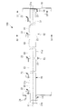
- FIG. 2 is a side view of the spray pipe 20 of the desulfurization apparatus 100 shown in FIG.
- a plurality of spray pipes 20 are inserted from the outside of the absorber 10 into the inside of the absorber 10.
- five spray pipes 20 arranged at predetermined positions in the vertical direction are arranged at equal intervals in the horizontal direction.
- the number of spray pipes 20 included in the desulfurization apparatus 100 may be any number other than five depending on the size of the absorption tower 10 or the like. Further, the spray pipes 20 may be disposed in a plurality of stages at different positions in the vertical direction.
- the spray pipe 20 is provided with a mounting flange (first flange portion) 24 and a supply port 25.
- the mounting flange 24 is a member for attaching the spray pipe 20 to the opening 14 (see FIG. 4) provided in the absorption tower 10.
- the mounting flange 24 is mounted to a mounting flange (second flange portion) (see FIGS. 12 and 17) disposed around the opening hole 14e of the opening 14 of the absorption tower 10 by a plurality of fasteners (not shown). .
- a manhole 15 is provided for a worker to pass through. The manhole 15 can be used also when bringing in parts for maintenance from the outside of the absorption tower 10 to the inside or when carrying out used parts from the inside of the absorption tower 10 to the outside.
- FIG. 3 is a plan view of the five spray pipes 20 shown in FIG. 2 as viewed from above.
- FIG. 4 is a view on arrow II of the spray pipe 20 of the desulfurization apparatus 100 shown in FIG.
- the spray pipe 20 has a pipe portion 21, a plurality of nozzle portions 22 (nozzle holders 22 b), and a plurality of leg portions 23.
- the pipe portion 21 is a cylindrical member extending linearly from the proximal end 21b to the distal end 21a along the horizontal axis X1 and having the distal end 21a closed.
- the proximal end 21b of the pipe portion 21 is provided with a supply port 25 to which the absorbent is supplied from the circulation pump 40, and an absorbent liquid supply pipe 41 (see FIG. 1) is connected around the supply port 25.
- a flange 26 is formed for this purpose.
- the absorbent supplied from the supply port 25 to the inside of the pipe 21 is guided to the plurality of nozzles 22.
- the length from the proximal end 21b to the distal end 21a along the axis X1 of the pipe portion 21 is 3 m or more and 15 m or less.
- the outer diameter of the pipe part 21 is 200 mm or more and 400 mm or less.
- the plurality of nozzle portions 22 are members disposed at equal intervals along the axis X1 at a plurality of locations on the upper end portion (upper portion) 21c in the vertical direction of the pipe portion 21.
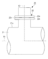
- FIG. 5 is a partially enlarged view of the nozzle portion 22 shown in FIG. As shown in FIG. 5, the nozzle portion 22 has a spray nozzle 22a, a nozzle holder 22b, and a gasket 22c.
- the spray nozzle 22a is a member for guiding the absorbent flowing in the horizontal direction along the axis X1 along the axis X1 along the axis X2 in the vertical direction.
- the spray nozzle 22 a discharges the absorption liquid supplied from the circulation pump 40 upward in the vertical direction, and brings the exhaust gas and the absorption liquid into gas-liquid contact inside the absorption tower 10.
- the spray nozzle 22a is detachably attached to the nozzle holder 22b, and is formed of, for example, SiC (silicon carbide).
- the nozzle holder 22 b is a member which is disposed at a plurality of locations on the upper end portion 21 c of the pipe portion 21 and which is formed in a cylindrical shape along the axis X 2 in the vertical direction.
- the nozzle holder 22 b guides the absorbing liquid flowing in the pipe portion 21 in the horizontal direction to the upper side in the vertical direction.
- the lower end side of the spray nozzle 22a is inserted into the nozzle holder 22b.
- a flange is formed at the upper end of the nozzle holder 22b.
- a flange having the same shape as that of the nozzle holder 22b is formed on the spray nozzle 22a.
- the flange of the spray nozzle 22a and the flange of the nozzle holder 22b are fastened by a plurality of fasteners (not shown) while sandwiching an annular gasket 22c (for example, made of butyl rubber) There is.
- the plurality of leg portions 23 are members attached to the lower end portion (lower portion) 21 d of the pipe portion 21.
- the legs 23 are attached to a plurality of places including the tip 21 a of the pipe 21.
- the plurality of leg portions 23 transmit the load of the pipe portion 21 to the pipe support (support portion) 91, the support beam (support portion) 92, and the support beam (support portion) 93 installed in the absorption tower 10.
- the pipe support 91, the support beam 92, and the support beam 93 are members installed in the absorption tower 10 to support the spray pipe 20.
- the reaction force when discharging the absorbing liquid applied to the pipe portion 21 and the impact force caused by the falling and contacting of the absorbing liquid are transmitted to the absorption tower 10 through the plurality of leg portions 23.
- the position of the lower end in the vertical direction of the leg portion 23 corresponds to the opening hole 14 e of the opening portion 14 in a state where the leg portion 23 is supported by the pipe support 91 and the support beams 92 and 93. It is installed in the absorption tower 10 so as to be lower than the lower end in the vertical direction (see FIG. 12).
- FIG. 6 is a II-II arrow view of the spray pipe 20 portion of the desulfurization apparatus 100 shown in FIG.
- FIG. 7 is a III-III arrow view of the spray pipe 20 portion of the desulfurization apparatus 100 shown in FIG.
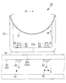
- the leg 23 shown in FIG. 6 and FIG. 7 is attached to the lower end 21 d of the tip 21 a of the pipe 21.
- the upper end of the leg portion 23 is attached to the pipe portion 21.
- the leg part 23 has the installation surface (1st surface) 23a in the lower end.
- the installation surface 23a is a flat installation surface along a horizontal surface, it may be another aspect.
- the installation surface 23a may have a polygonal or arc shape in cross section orthogonal to the axis X1.
- a pipe support 91 formed of a metal material or the like is installed on the inner wall surface of the absorption tower 10.
- the pipe support 91 has a support surface (second surface) 91 a for supporting the spray pipe 20 at its upper end.
- the support surface 91a is a flat installation surface along a horizontal surface, but may be in another aspect.
- the support surface 91a may have a polygonal or arc shape in cross section orthogonal to the axis X1.
- the upper surface of the support surface 91a may be coated with a resin lining to protect the support surface 91a from corrosion and the like.
- a shim plate (plate member) 99 is disposed between the mounting surface 23a at the lower end of the leg portion 23 and the support surface 91a at the upper end of the pipe support 91.
- the leg portion 23 is disposed in a state where the installation surface 23 a is opposed to the support surface 91 a. That is, the spray pipe 20 is supported by the pipe support 91 in a state where the installation surface 23 a is opposed to the support surface 91 a. Therefore, the rotation direction angle around the axial center of the pipe portion 21 is determined based on the support surface 91a.
- the axis of the spray nozzle 22a attached to the pipe portion 21 has a rotational direction angle along the vertical direction
- the time and effort of adjusting the rotational direction angle of the pipe portion 21 becomes unnecessary.
- the pipe portion 21 is supported by the pipe support 91 by the “face” via the leg portion attached to the pipe portion 21, for example, when the pipe portion is directly supported by the pipe support without providing the leg portion Compared to the above, the local stress applied to the portion of the pipe portion 21 in contact with the pipe support 91 can be reduced, and further, the pipe portion 21 is subjected to the reaction force accompanying the discharge of the absorbing liquid and the impact force due to the falling absorbing liquid. It is possible to reduce the possibility that the rotational direction angle of the above is deviated and the discharge direction of the absorbing liquid does not follow the vertical direction.
- the shim plate 99 is a member for adjusting the position of the installation surface 23 a in the vertical direction with respect to the support surface 91 a in order to install the pipe portion 21 in the horizontal direction. 6 and 7, the shim plate 99 is disposed between the installation surface 23a and the support surface 91a, but if it is not necessary to install the pipe portion 21 in the horizontal direction, the shim plate 99 is used. It does not have to be arranged. In that case, the installation surface 23a and the support surface 91a are disposed in direct contact with each other. Further, the shim plate 99 can be used with the appropriate thickness in the vertical direction in order to install the pipe portion 21 in the horizontal direction. In addition, a plurality of shim plates 99 may be stacked and disposed.
- the fastening portion 70 includes a fastening bolt 71 having a head and a shaft, a washer 72 disposed between the head of the fastening bolt 71 and the pipe support 91, and a fastening that is fastened to the shaft of the fastening bolt 71. It has nuts 73 and 74 and a washer 75 disposed between the fastening nut 74 and the leg 23.
- a clearance is provided below the fastening nut 74, and the fastening nut 73 is tightened in that state, or after the fastening nut 74 is tightened, the fastening nut 73 is tightened and the fastening nut 74 is loosened.
- the fastening nut 73 and the fastening nut 74 can be in a fastening state in which they do not move in the vertical direction. In this case, even when the pipe portion 21 is deformed by thermal expansion, it is possible to suppress a defect that the deformation or breakage occurs in the fastening portion.
- FIG. 8 is a view on arrow IV-IV of the spray pipe 20 of the desulfurization apparatus 100 shown in FIG.
- FIG. 9 is a VV arrow view of the spray pipe 20 portion of the desulfurization apparatus 100 shown in FIG.
- the leg portion 23 shown in FIGS. 8 and 9 is attached to an intermediate portion between the distal end portion 21 a and the proximal end portion 21 b of the pipe portion 21.
- the upper end of the leg portion 23 is attached to the pipe portion 21.
- the leg part 23 has the installation surface (1st surface) 23a in the lower end.
- the installation surface 23a is a flat installation surface along a horizontal surface, it may be another aspect.
- the installation surface 23a may have a polygonal or arc shape in cross section orthogonal to the axis X1.
- a support beam 92 and a support beam 93 which are formed of a metal material or the like and extend in the horizontal direction are installed.
- the support beam 92 has a support surface (second surface) 92a at its upper end.
- the support beam 93 has a support surface (second surface) 93a at its upper end.
- the support surfaces 92a and 93a are flat installation surfaces along the horizontal surface, but may be other embodiments.
- the support surfaces 92a and 93a may have a polygonal or arc shape in cross section orthogonal to the axis X1.
- the upper surfaces of the support surfaces 92a, 93a may be coated with a resin lining to protect the support surfaces 92a, 93a from corrosion and the like.
- a shim plate 99 is disposed between the mounting surface 23 a at the lower end of the leg 23 and the support surfaces 92 a and 93 a at the upper end of the support beams 92 and 93.
- the leg portion 23 is disposed in a state in which the mounting surface 23a is opposed to the support surfaces 92a and 93a.
- the spray pipe 20 is supported by the support beams 92, 93 in a state where the installation surface 23a is opposed to the support surfaces 92a, 93a.
- the rotation direction angle around the axial center of the pipe portion 21 is determined based on the support surfaces 92a and 93a.
- the axial center of the spray nozzle 22a attached to the pipe portion 21 (nozzle holder 22b) has a rotational direction angle along the vertical direction
- the pipe portion 21 is supported by the support beams 92 and 93 in a “face” manner via the leg portions attached to the pipe portion 21, for example, the support beam 92 directly without providing the leg portion in the pipe portion Compared with the case of supporting by 93, the local stress applied to the portion of the pipe portion 21 in contact with the support beams 92, 93 can be reduced, and further, the reaction force accompanying the discharge of the absorbing liquid and the impact force due to the falling of the absorbing liquid As a result, it is possible to reduce the possibility that the rotational direction angle of the pipe portion 21 is deviated and the discharge direction of the absorbing liquid is not along the vertical direction.
- the shim plate 99 is a member that adjusts the vertical position of the installation surface 23a with respect to the support surfaces 92a and 93a in order to install the pipe portion 21 in the horizontal direction.
- the shim plate 99 is disposed between the installation surface 23a and the support surfaces 92a and 93a, but if it is not necessary to install the pipe portion 21 along the horizontal direction, the shim plate It is not necessary to place 99.
- the installation surface 23a and the support surfaces 92a and 93a are disposed in direct contact with each other.
- the shim plate 99 can be used with the appropriate thickness in the vertical direction in order to install the pipe portion 21 in the horizontal direction.
- a plurality of shim plates 99 may be stacked and disposed.
- the leg portion 23, the support beams 92 and 93, and the shim plate 99 are fastened by a fastening portion (second fastening portion) 80.
- the fastening portion 80 is fastened to a fastening bolt 81 having a head and a shaft, a washer 82 disposed between the head of the fastening bolt 81 and the support beams 92 and 93, and a shaft of the fastening bolt 81 And a washer 85 disposed between the fastening nut 84 and the leg 23.
- the reason why the two fastening nuts 83 and 84 are fastened to the shaft portion of the fastening bolt 81 is to make it possible to provide a gap below the fastening nut 84.
- the spray pipe 20 is formed by integrally forming the pipe portion 21, the nozzle holder 22b of the nozzle portion 22, and the leg portion 23 with fiber-reinforced plastic.
- the spray nozzle 22a attached to the nozzle holder 22b is made of, for example, SiC (silicon carbide).
- the spray pipe 20 of the present embodiment is manufactured by integrally forming the pipe portion 21, the nozzle holder 22b of the nozzle portion 22, and the leg portion 23 of fiber reinforced plastic.
- the spray pipe 20 is highly likely to be abraded due to the absorption liquid discharged upward falling and colliding.
- the fiber reinforced plastic since the fiber reinforced plastic is used for the spray pipe 20, the wear resistance is high. Furthermore, the resistance to corrosion is also high.
- a metal material for example, UNS S31254 or Hastelloy C-276 may be used instead of the fiber reinforced plastic.
- 316 L or the like may be used.
- the leg portion 23 may be separately manufactured of a metal material and attached to the spray pipe 20 by welding or screw connection.
- the leg portion 23 is a rigid body.
- FIG. 10 is a cross-sectional view of the leg 23 shown in FIG. 9 taken along the line VI-VI.
- the installation surface 23a of the leg portion 23 is formed with an insertion hole 23b into which the fastening bolt 81 is inserted.
- the insertion hole 23b has a length L2 in the direction along the axis X1 longer than the length L1 in the direction orthogonal to the axis X1.
- the reason why the insertion hole 23b is a long hole is that the insertion hole 23b contacts the fastening bolt 81 when the spray pipe 20 is thermally expanded and the leg 23 moves toward the tip 21a of the pipe 21. It is for suppressing.
- the insertion holes 23b provided in the installation surface 23a of the legs 23 are elongated holes, and the insertion holes (not shown) provided in the pipe support 91 and the support beams 92 and 93 are circular holes.
- the insertion hole 23b provided in the installation surface 23a of the leg portion 23 is a circular round hole, and the insertion hole provided in the pipe support 91 and the support beams 92, 93 has an axial line rather than the length L1 in the direction orthogonal to the axial line X1.
- the length L2 in the direction along X1 may be a long hole.
- both the insertion holes 23b provided in the installation surface 23a of the legs 23 and the insertion holes provided in the pipe support 91 and the support beams 92 and 93 may be long holes.
- FIG. 11 is a VI-VI arrow view of the plate-like member shown in FIG.
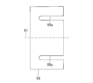
- the shim plate 99 is formed with a notch 99a opening toward one end.
- the cutaway portion 99a is a portion which allows the fastening bolt 81 to be inserted in a state of being disposed between the installation surface 23a of the leg portion 23 and the support surfaces 92a and 93a of the support beams 92 and 93.
- the notch 99a is a portion that enables the fastening bolt 71 to be inserted in a state (see FIG. 7) disposed between the installation surface 23a of the leg 23 and the support surface 91a of the pipe support 91.
- the shim plate 99 Since the shim plate 99 has the notch 99 a, it can be inserted between the mounting surface 23 a of the leg 23 and the support surface 91 a of the pipe support 91 without removing the fastening bolt 71. Similarly, since the shim plate 99 has the notch 99a, the shim plate 99 can be inserted between the mounting surface 23a of the leg 23 and the support surfaces 92a, 93a of the support beams 92, 93 without removing the fastening bolt 81. it can. As described above, when installing the leg portion 23 of the spray pipe 20 to the pipe support 91 and the support beams 92 and 93, the spray pipe 20 is disposed in the horizontal direction by installing the shim plate 99 at an appropriate position. Can be adjusted to
- the shim plate 99 is disposed in a state in which the notch 99a is open toward the tip 21a of the pipe portion 21 along the axis X1. That is, the notch 99 a of the shim plate 99 is not open at the proximal end 21 b side of the pipe portion 21. Therefore, the shim plate 99 does not move toward the tip 21a because the shim plate 99 contacts the fastening bolts 71 and 81 even if a force directed to the tip 21a is applied from the leg 23. Therefore, the problem that the shim plate 99 moves toward the tip end portion 21a and falls off the pipe support 91 and the support beams 92 and 93 can be prevented.
- a clearance CL is formed between the tip 21 a of the pipe portion 21 and the inner wall surface of the absorber 10.
- the clearance CL is a distance necessary for the tip 21 a of the pipe portion 21 not to contact the inner wall surface of the absorption tower 10.
- the spray pipe 20 is thermally expanded by the high temperature exhaust gas. Therefore, the pipe portion 21 of the present embodiment is disposed such that the clearance CL can be secured even in the state where the spray pipe 20 is heated by the exhaust gas.
- the pipe portion 21 is installed so that the clearance CL can be secured even if the thermal expansion occurs.
- the clearance CL between the tip 21 a of the pipe portion 21 and the inner wall surface of the absorption tower 10 is 10 mm or more and 100 mm or less in a state where the exhaust gas is not heated.
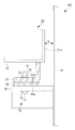
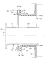
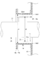
- FIG. 12 is a partially enlarged view of the mounting flange 24 portion of the spray pipe 20 of the desulfurization apparatus 100 shown in FIG.
- the opening 14 of the absorption tower 10 is formed in a tubular shape so as to open toward the side of the absorption tower 10 and to extend along the axis X1.
- the opening 14 has an opening 14 e that opens to the side.
- a flange (second flange portion) 14 a disposed around the opening hole 14 e is formed.
- a resin-made lining portion 14b is provided on the inner peripheral surface of the flange 14a to protect the flange 14a from corrosion or the like due to exhaust gas.
- the mounting flange 24 of the spray pipe 20 has a mounting surface (first mounting surface) 24 a that protrudes from the outer peripheral surface of the pipe portion 21 and extends in the vertical direction.
- first mounting surface first mounting surface
- second mounting surface second mounting surface
- the mounting surface 24a and the mounting surface 14d are mounted in a state of facing each other across the gasket 14c.
- the mounting flange 24 of the spray pipe 20 is attached to the flange 14 a of the opening 14 by a fastening portion (first fastening portion) 50 with the gasket 14 c (for example, made of butyl rubber) interposed therebetween.
- the first fastening portion 50 includes a fastening bolt 51 having a head and a shaft, a washer 52 disposed between the head of the fastening bolt 51 and the mounting flange 24, and a fastening bolt And a fastening nut 53 fastened to the shaft portion 51.
- the first fastening portions 50 are shown only at the two upper and lower places in the vertical direction, but the first fastening portions 50 are provided at a plurality of places so as to surround the outer peripheral end of the mounting flange 24. .
- the mounting flange 24 of the spray pipe 20 and the flange 14 a of the opening 14 are detachably mounted by a fastener including a fastening bolt 51 and a fastening nut 53. Therefore, when replacing or inspecting the spray pipe 20, the spray pipe 20 can be easily removed from the absorption tower 10 by releasing the fastening between the fastening bolt 51 and the fastening nut 53.
- the desulfurization apparatus 100 of this embodiment is provided with five spray pipes 20 as shown in FIG. Moreover, the absorption tower 10 with which the desulfurization apparatus 100 of this embodiment is equipped has five flanges 14a disposed around the opening hole 14e formed at five places equal to the number of the spray pipes 20 and five flanges 14a. Equipped with And five attachment flanges 24 of five spray pipes 20 are attached to each of five flange 14a by one to one.
- the desulfurization apparatus 100 according to the present embodiment includes five spray pipes 20, the number may be an arbitrary number. In this case, the absorption tower 10 is provided with the same number of opening holes 14 e as the spray pipes 20 and the flanges 14 a disposed around the opening holes 14 e.
- the spray pipe 20 attached to the opening 14 via the mounting flange 24 is inclined from the horizontal direction. Therefore, the thickness of the portion of the lining portion 14b to be held by the mounting flange 24 is appropriately adjusted so that the end face of the opening portion 14 coincides with the vertical direction.
- a sealing material may be applied between the mounting flange 24 and the gasket 14 c so that the end face of the opening 14 coincides with the vertical direction. The application of the sealing material may be performed instead of adjusting the thickness of the lining portion 14b, or may be performed in addition to adjusting the thickness of the lining portion 14b.
- the mounting surface 14d of the opening 14 and the mounting surface 24a formed on the mounting flange 24 of the spray pipe 20 are opposed to each other with the gasket 14c interposed therebetween. It is attached to the opening 14 of the absorber 10.
- the lower end 14eB of the opening 14e is lower than the lower end 21d of the pipe 21 in the vertical direction, and the upper end 14eA of the opening 14e is higher than the upper end 21c of the pipe 21.
- the pipe portion 21 is disposed in such a state that the lower end portion 21d does not contact the inner peripheral surface of the opening portion 14 and the opening hole 14e.
- the spray pipe 20 is attached to the opening portion 14 so that the position in the vertical direction of the axis X1 along which the pipe portion 21 extends is lower than the vertical center position of the opening hole 14e. ing.
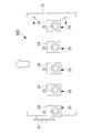
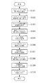
- FIG. 13 is a flowchart showing an installation method of installing the spray pipe 20 inside the absorption tower 10.
- Each process shown in FIG. 13 is a process executed by a worker or work equipment such as a crane operated by the worker.
- step S1301 the operator lifts the spray pipe 20 placed outside the absorption tower 10 by a crane (not shown) and inserts the spray pipe 20 into the opening 14 of the absorption tower 10 in the horizontal direction. Do. The worker adjusts the position of the pipe portion 21 with a guide rope (not shown) connected to the pipe portion 21 so that the spray pipe 20 does not contact the absorption tower 10. As shown in FIG. 14, the spray pipe 20 is inserted into the opening 14 of the absorption tower 10 in a state where the spray nozzle 22a is not attached to the nozzle holder 22b.
- the height H1 in the vertical direction from the lower end 14eB to the upper end 14eA of the opening hole 14e is from the installation surface 23a of the leg 23 to the nozzle holder 22b. It is higher than the height H2 in the vertical direction up to the upper end 22bA. This is done to allow the spray pipe 20 to be inserted into the interior of the absorber 10 through the opening 14 without the spray nozzle 22a attached to the nozzle holder 22b.
- step S1302 the worker arranges the spray pipe 20 inserted into the inside of the absorption tower 10 from the opening 14 inside the absorption tower 10 so as to be supported by the plurality of legs 23. As shown in FIG. 2, the worker sprays so that the installation surfaces 23 a of the plurality of legs 23 face the support surface 91 a of the pipe support 91 and the support surfaces 92 a and 93 a of the support beams 92 and 93. Arrange the pipe 20.
- step S1303 the operator corrects the verticality of the mounting surface 14d such that the mounting surface 24a of the mounting flange 24 is disposed along the vertical direction.
- the correction of the vertical degree of the mounting surface 14d is performed, for example, by adjusting the thickness of the lining portion 14b.
- the thickness of the sealant for example, made of silicone
- the mounting surface 24a of the mounting flange 24 is disposed along the vertical direction.
- step S1304 temporary tightening process
- the operator temporarily tightens the mounting flange 24 of the spray pipe 20 and the flange 14a of the opening 14 of the absorption tower 10 using the first fastening portion 50.
- the plurality of first fastening portions 50 are provisionally It is connected by tightening.
- step S1305 the operator temporarily tightens the mounting flange 24 and the flange 14a of the opening 14 so that the axis X1 of the pipe portion 21 coincides with the horizontal direction. Adjust the degree.
- the term “horizontal direction” as used herein includes an angle within the range of desired tolerance from the horizontal direction (the same applies hereinafter).
- the worker inserts the thickness of the shim plate 99 inserted between the pipe support 91 and the leg 23, the thickness of the shim plate 99 inserted between the support beam 92 and the leg 23, the support beam
- the thickness of the shim plate 99 to be inserted between 93 and the leg 23 is appropriately selected, and the height of the mounting surface 23a with respect to the support surfaces 91a, 92a, 93a is adjusted.
- the operator arranges a horizontal scale (not shown) on the upper surface of the nozzle holder 22b of the spray pipe 20 and visually checks the horizontal scale to check whether the axis X1 of the pipe portion 21 coincides with the horizontal direction Do. When the operator confirms that the levelness indicated by the leveler is within the desired tolerance, the operator ends the adjustment of the levelness.
- step S1305 adjusts the levelness of the pipe portion 21 in step S1305 (adjustment step), and then, the leg disposed adjacent to the pipe support 91 and the tip 21a of the spray pipe 20 in step S1306 (connection step)
- the part 23 is connected by the fastening part 70.
- the operator inserts the shaft portion of the fastening bolt 71 from the lower side of the pipe support 91, and fastens the fastening nuts 73 and 74 to the shaft portion which penetrates the leg portion 23, thereby the pipe support 91 and the leg portion Connect 23
- the pipe support 91 and the leg 23 may be temporarily tightened in the connecting step of step S1306 so that the distance between the mounting flange 24 and the opening 14 can be finely adjusted in step S1308 (final tightening step) to be performed later.
- step S1306 even when the pipe portion 21 is thermally expanded, the pipe support 91 and the leg portion 23 are connected in a state in which the leg portion 23 attached to the pipe portion 21 can move along the axis X1. Be done.
- step S1307 connection step
- the worker connects the support beams 92 and 93 and the leg portion 23 by the fastening portion 80. Specifically, the worker inserts the shaft portion of the fastening bolt 81 from the lower side of the support beams 92 and 93, and fastens the fastening nuts 83 and 84 to the shaft portion penetrating the leg portion 23, thereby supporting the support beam 92, 93 and the leg 23 are connected.
- the support beams 92 and 93 and the leg portion 23 are temporarily tightened so that the distance between the mounting flange 24 and the opening 14 can be finely adjusted in step S1308 (final tightening step) to be performed later. Good.
- step S1307 even when the pipe portion 21 is thermally expanded, the support beams 92 and 93 and the leg portion 23 can be moved with the leg portion 23 attached to the pipe portion 21 movable along the axis X1. Are linked.
- connection between the support beam 92 and the leg 23 is performed prior to the connection between the support beam 93 and the leg 23.
- the connection process of step S1307 is performed in order from the distal end portion 21a of the pipe portion 21 to the proximal end portion 21b.
- step S1308 the final tightening step
- the operator checks the gap between the mounting flange 24 of the spray pipe 20 and the opening 14 of the absorption tower 10, and confirms that there is no excessive gap. If a gap is present, the position of the spray pipe 20 is finely adjusted to eliminate the gap. Thereafter, the mounting flange 24 and the flange 14 a of the opening 14 are fully tightened using the first fastening portion 50.
- the mounting flange 24 of the spray pipe 20 and the flange 14a of the opening 14 face each other with the mounting surface 24a of the mounting flange 24 and the mounting surface 14d of the flange 14a sandwiching the gasket 14c.
- the plurality of first fastening portions 50 are connected by being fully tightened.
- full tightening refers to increasing the torque (Nm) and tightening the first fastening portion 50 temporarily tightened in step S1304.
- steps S1301 to S1308 the method for installing one spray pipe 20 has been described. However, by repeating steps S1301 to S1308, a plurality of spray pipes 20 are installed.
- step S1309 installation step
- the worker carries in a plurality of scaffolding boards (scaffolding members) 60 from the outside of the absorption tower 10 via the manhole 15 into the interior of the absorption tower 10, and as shown in FIG. It is installed at the upper end 21 c of the pipe portion 21 of the pipe 20.
- the scaffolding plate 60 is placed around each of the plurality of spray pipes 20.
- the scaffolding plate 60 is a member on which a worker rests and works to attach the spray nozzle 22a to the nozzle holder 22b of the pipe portion 21.
- step S1310 the worker mounts the spray nozzle 22a on the nozzle holder 22b in a state of being placed on the scaffolding plate 60.
- the operator attaches the spray nozzle 22a to the nozzle holder 22b while moving on the scaffold plate 60 with respect to the plurality of nozzle holders 22b provided in the plurality of spray pipes 20.
- step S1306 connection process
- step S1307 connection process
- the worker After attaching the spray nozzles 22a to all the nozzle holders 22b, and after the final tightening is completed, the worker takes a plurality of scaffolding plates 60 through the manholes 15 as the absorber 10. Take out of the Then, the worker moves from the manhole 15 to the outside of the absorber 10 and ends the process according to the present flow.
- the mounting flange 24 of the spray pipe 20 disposed inside the absorption tower 10 and the flange 14 a disposed around the opening hole 14 e of the absorption tower 10 are removable. Is attached to The spray pipe 20 can be easily removed from the absorption tower 10 for replacement or inspection, so that it is easy to replace or inspect the spray pipe 20 if a failure such as damage or clogging occurs in part of the spray pipe 20. It is possible to do
- the mounting surface 24a of the mounting flange 24 of the spray pipe 20 is made to face the mounting surface 14d of the flange 14a of the opening 14 of the absorption tower 10, and mounting along the vertical direction
- the spray pipe 20 can be attached to the opening 14 of the absorber 10 using the surface 14 d as a reference surface. Therefore, it is possible to reduce the number of steps for adjusting the axial direction of the pipe portion 21 of the splay pipe 20 in the horizontal direction so that the rotation direction angle about the axial center becomes a predetermined angle. The work when inserting from the outside of the tower 10 and installing inside becomes easy.
- the mounting flange 24 of the spray pipe 20 is fastened to the flange 14 a of the opening 14 of the absorption tower 10, and the spray pipe 20 is attached to the absorption tower 10. It is possible to prevent the absorption liquid and the exhaust gas from leaking out through the opening 14 (opening hole 14 e) of the tower 10.
- the desulfurization apparatus 100 of the present embodiment includes a predetermined number (five) of spray pipes 20, and the absorption tower 10 has a predetermined number (five places) of opening holes 14e and a predetermined number (five) of flanges 14a. And a predetermined number (five) of mounting flanges 24 are attached to each of a predetermined number (five) of the flanges 14 a in a one-to-one manner. By doing this, it is possible to remove from the absorption tower 10 only the spray pipes 20 that need to be replaced or inspected among the predetermined number of spray pipes 20.
- the position in the vertical direction of the axis X1 in which the pipe portion 21 extends is disposed lower than the central position in the vertical direction of the opening hole 14e.
- a sufficient space is secured above the pipe portion 21, so the installation work of the pipe portion 21 can be easily performed.
- the installation work can be performed while moving the pipe part 21 downward along the gravity after inserting the pipe part 21 into the opening hole 14e, the installation work of the pipe part 21 is facilitated and the installation accuracy is also improved.
- the pipe part 21 is arrange
- the spray pipe 20 includes the leg portion 23 attached to the lower portion in the vertical direction of the pipe portion 21 and having the installation surface 23a, and the position of the lower end in the vertical direction of the leg portion 23 is , And the lower end of the opening hole 14e in the vertical direction.
- the installation work can be performed while moving the leg portion 23 pulled up above the opening hole 14 e downward along the gravity when passing the opening hole 14 e of the absorption tower 10. Therefore, the installation work at the time of installing the leg portion 23 of the spray pipe 20 on the pipe support 91 and the support beams 92 and 93 provided in the absorption tower 10 can be easily and accurately performed.
- the lower end 14eB of the opening 14e is lower than the lower end 21d of the pipe 21 in the vertical direction, and the upper end of the opening 14e is lower than the upper end 21c of the pipe 21.
- the part 14eA is disposed high. Therefore, after the pipe portion 21 is inserted from the outside of the absorption tower 10 to the inside along the horizontal direction from the opening hole 14e of the opening portion 14, the pipe portion 21 is positioned vertically at the upper end 14eA and the lower end 14eB of the opening 14e. It is installed in the inside of the absorber 10 in the state maintained between.
- the amount of movement of the spray pipe 20 in the vertical direction from the insertion into the interior of the absorption tower 10 to the installation thereof is small. Therefore, when the spray pipe 20 is inserted from the outside of the absorber 10 and installed inside, the levelness of the spray pipe 20 can be accurately maintained.
- a gap is secured between the upper end 21c of the pipe portion 21 and the upper end 14eA of the opening hole 14e, and a gap is secured between the lower end 21d of the pipe portion 21 and the lower end 14eB of the opening hole 14e. . Therefore, when the spray pipe 20 is inserted from the outside of the absorption tower 10, it is possible to allow the pipe portion 21 to move in the vertical direction to some extent.
- the height of the perpendicular direction of the spray pipe 20 Is the height H2 from the mounting surface 23a of the leg 23 to the upper end 22bA of the nozzle holder 22b.
- the height H1 from the lower end portion 14eB of the opening hole 14e to the upper end portion 14eA is higher than the height H2 of the spray pipe 20 in the vertical direction. Therefore, the spray pipe 20 having the legs 23 can be inserted from the outside to the inside of the absorber 10 through the opening hole 14e.
- the spray nozzle 22a is attached to each of the plurality of nozzle holders 22b, so that the absorbing liquid can be discharged from the spray pipe 20.
- the opening 14 formed on the side surface of the absorption tower 10 is configured by a rectangular opening 14 e and a rectangular flange 14 a around the opening 14 e.
- the opening hole 14e is rectangular, the position of the spray pipe 20 can be changed and adjusted in a wide range in both the vertical direction and the horizontal direction, and the installation of the spray pipe 20 becomes easy.
- the shapes of the mounting flange 24 and the flange 14a may be rectangular.
- the rectangle includes not only a shape in which four corners are orthogonal but also a partially rounded shape.
- the flanges 14a and the mounting flanges 24 are the upper left and right two places in the vertical direction and the lower left and right in the vertical direction. Although it was a rectangular shape which has a corner in each of two places, another aspect may be sufficient.
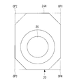
- the flange 14a and the mounting flange 24 may be shaped as shown in FIG.
- FIG. 15 is a view of the desulfurization apparatus from the side of the absorption tower 10.
- the flange 14a and the mounting flange 24A are horizontal with the horizontal line passing through the upper end and the lower end in the vertical direction.
- the four corner portions CP1, CP2, CP3, and CP4 where the left end and the right end of the direction intersect with each other may be cut away.
- the flange 14a is not shown in figure, suppose that it is the same shape as the attachment flange 24A.
- the work space of the worker is sufficiently secured.
- the worker cuts off the corner parts.
- the installation work of the spray pipe 20 is facilitated, for example, since it is possible to work by putting a hand on the back side of the flange from an essential part.
- the flange 14a and the mounting flange 24A may have other shapes as long as the corner portions CP1, CP2, CP3, and CP4 are notched. For example, instead of the octagonal shape shown in FIG. 15, each corner may be rounded. Also, the flange 14a and the mounting flange 24A may be formed in an elliptical shape.
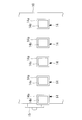
- the center position of the left end and the right end of the mounting flange 24 and the center position of the pipe portion 21 are horizontal.
- the center position C1 of the left end l and the right end r of the mounting flange 24B and the center position C2 of the pipe portion 21 are horizontal. It may be separated.
- the center position C1 of the left end l and the right end r of the mounting flange 24B and the center position C3 of the pipe portion 21 are horizontal. It may be spaced apart in the direction.
- the desulfurization apparatus 100 is an apparatus using a lime gypsum method in which an absorbing liquid containing lime is brought into gas-liquid contact with exhaust gas to remove sulfur oxides contained in the exhaust gas. May be For example, it may be a desulfurization apparatus using a seawater desulfurization method that uses seawater containing an alkaline component as an absorbent.
- the spray pipe 20 is disposed along the horizontal direction inside the absorption tower 10, but the spray pipe 20 may be disposed inclined at an angle from the horizontal direction. .
- the mounting flange 24 of the spray pipe 20 is attached to the flange 14 a of the opening 14 of the absorption tower 10, but another embodiment may be employed.
- the mounting flange 24 may be directly attached to the side wall of the absorption tower 10 using a fastener.
- the portion surrounding the opening in the side wall of the absorption tower 10 is a flange portion to which the mounting flange 24 of the spray pipe 20 is attached.
Landscapes
- Chemical & Material Sciences (AREA)
- Engineering & Computer Science (AREA)
- Chemical Kinetics & Catalysis (AREA)
- Environmental & Geological Engineering (AREA)
- Analytical Chemistry (AREA)
- General Chemical & Material Sciences (AREA)
- Oil, Petroleum & Natural Gas (AREA)
- Health & Medical Sciences (AREA)
- Biomedical Technology (AREA)
- Treating Waste Gases (AREA)
- Gas Separation By Absorption (AREA)
- Nozzles (AREA)
Abstract
吸収塔の内部にスプレイパイプを容易かつ正確に配置することが可能な脱硫装置を提供する。吸収塔(10)と、吸収塔(10)の内部に配置されるスプレイパイプ(20)と、を備え、スプレイパイプ(20)が、先端部が閉塞された筒状のパイプ部(21)と、パイプ部(21)に取り付けられる取付フランジ(24)と、を備え、吸収塔(10)が、側方に向けて開口する開口穴(14e)と、開口穴(14e)の周囲に配置されるフランジ(14a)と、を備え、取付フランジ(24)とフランジ(14a)とが、着脱可能に取り付けられている脱硫装置を提供する。
Description
本開示は、吸収塔とスプレイパイプとを備えた脱硫装置に関するものである。
発電所等に設置されるボイラ等の排ガス系統には、排ガスから硫黄酸化物を除去する脱硫装置が設けられる。これにより、大気に排出される排ガスに含まれる硫黄酸化物を低減できる。特許文献1および特許文献2には、水平に設置されるスプレイパイプ(枝管、ヘッダ)に設けられた複数のノズルから吸収液を上方へ吐出し、燃焼排ガスと吸収液の間の化学反応で燃焼排ガス中の硫黄酸化物を除去する液柱式の脱硫装置が開示されている。
液柱式の脱硫装置において、スプレイパイプには、吸収液を上方に吐出するのに伴って下方へ向けた反力が加わる。また、スプレイパイプには、上方に吐出した吸収液が落下してスプレイパイプに接触する際にも下方へ向けた衝撃力が加わる。そのため、かかる反力や衝撃力を受けたとしても、破損に至らないように、スプレイパイプを吸収塔内に設置する必要がある。また、液柱式の脱硫装置において、吸収液を効果的に排ガスと気液接触させるためには、吸収液をスプレイパイプのノズルから鉛直方向に沿って吐出する必要がある。特に、液柱高さが高い場合には、液頭が傾くと、ガス抵抗に分布が生じて脱硫性能に影響が出ることとなる。例えば液高さ13mで吐出角度が鉛直方向から0.5°ずれた場合、液頭は0.1m横方向にずれることとなる。そのため、スプレイパイプを、排ガスの通路となる吸収塔の内部に、正確に設置する必要がある。
特許文献1には、吸収剤スラリ供給管4の噴霧用枝管5が吸収塔2を貫通する図が示されている。噴霧用枝管5が貫通する吸収塔2の開口穴から外部への吸収剤や排ガスの漏れを防止するためには、開口穴と噴霧用枝管5とを溶接により接合し、あるいは開口穴と噴霧用枝管5との間にコーキング材を充填する必要がある。
また、特許文献2には、枝管(ヘッダ)14,15がシェル12を貫通する図が示されている。特許文献2においては、枝管14,15が貫通するシェル12の開口穴に貫通ポート18,19を設けることにより、開口穴と枝管14,15との間の隙間を無くしている。
また、特許文献2には、枝管(ヘッダ)14,15がシェル12を貫通する図が示されている。特許文献2においては、枝管14,15が貫通するシェル12の開口穴に貫通ポート18,19を設けることにより、開口穴と枝管14,15との間の隙間を無くしている。
しかしながら、特許文献1および特許文献2のように、吸収塔とスプレイパイプとを開口穴の部分で溶接やコーキング材等で固定してしまうと、交換や点検のために枝管(スプレイパイプ)を吸収塔から取り外すことが困難となる。そのため、スプレイパイプの一部に損傷や詰まり等の不具合が生じた場合に、その不具合を解消するための作業工程が煩雑となり作業時間も長くなってしまう。
本開示は、このような事情に鑑みてなされたものであって、スプレイパイプの一部に損傷や詰まり等の不具合が生じた場合に、スプレイパイプの交換や点検を容易に行うことが可能な脱硫装置を提供することを目的とする。
上記課題を解決するために、本開示は以下の手段を採用する。
本開示の一態様にかかる脱硫装置は、排ガスの通路となる吸収塔と、前記吸収塔の内部に配置されるスプレイパイプと、を備え、前記スプレイパイプが、先端部が閉塞された筒状のパイプ部と、前記パイプ部に取り付けられる第1フランジ部と、を備え、前記吸収塔が、側方に向けて開口する開口穴と、該開口穴の周囲に配置される第2フランジ部と、を備え、前記第1フランジ部と前記第2フランジ部とが、着脱可能に取り付けられている。
本開示の一態様にかかる脱硫装置は、排ガスの通路となる吸収塔と、前記吸収塔の内部に配置されるスプレイパイプと、を備え、前記スプレイパイプが、先端部が閉塞された筒状のパイプ部と、前記パイプ部に取り付けられる第1フランジ部と、を備え、前記吸収塔が、側方に向けて開口する開口穴と、該開口穴の周囲に配置される第2フランジ部と、を備え、前記第1フランジ部と前記第2フランジ部とが、着脱可能に取り付けられている。
本開示の一態様にかかる脱硫装置によれば、吸収塔の内部に配置されるスプレイパイプの第1フランジ部と、吸収塔が有する開口穴の周囲に配置される第2フランジ部とが、着脱可能に取り付けられている。交換や点検のためにスプレイパイプを吸収塔から容易に取り外すことができるため、スプレイパイプの一部に損傷や詰まり等の不具合が生じた場合に、スプレイパイプの交換や点検を容易に行うことが可能となる。
本開示の一態様にかかる脱硫装置は、所定数の前記スプレイパイプを備え、前記吸収塔が、前記所定数の前記開口穴と、前記所定数の前記第2フランジ部と、を備え、前記所定数の前記第2フランジ部のそれぞれに、前記所定数の前記第1フランジ部が一対一で取り付けられているものであってよい。
このようにすることで、所定数のスプレイパイプのうち交換や点検が必要なスプレイパイプのみを、吸収塔から取り外すことができる。そのため、吸収塔の1つの開口穴に複数のスプレイパイプが取り付けられている場合に比べ、スプレイパイプの交換や点検を容易に行うことができる。また、吸収塔の開口穴とスプレイパイプが一対一で対応しているため、スプレイパイプを吸収塔に設置する際の設置作業を容易かつ正確に行うことができる。
このようにすることで、所定数のスプレイパイプのうち交換や点検が必要なスプレイパイプのみを、吸収塔から取り外すことができる。そのため、吸収塔の1つの開口穴に複数のスプレイパイプが取り付けられている場合に比べ、スプレイパイプの交換や点検を容易に行うことができる。また、吸収塔の開口穴とスプレイパイプが一対一で対応しているため、スプレイパイプを吸収塔に設置する際の設置作業を容易かつ正確に行うことができる。
本開示の一態様にかかる脱硫装置は、前記パイプ部の軸線が水平方向に沿って延び、前記軸線の鉛直方向の位置が、前記開口穴の鉛直方向の中心位置よりも低く配置されてもよい。
このようにすることで、パイプ部を開口穴に設置する際にパイプ部の上方に十分な空間が確保されるため、パイプ部の設置作業を容易に行うことができる。また、パイプ部を開口穴に挿入した後にパイプ部を重力に沿って下方に移動させながら設置作業を行うことができるため、パイプ部の設置作業が容易になるとともに設置精度も向上する。
このようにすることで、パイプ部を開口穴に設置する際にパイプ部の上方に十分な空間が確保されるため、パイプ部の設置作業を容易に行うことができる。また、パイプ部を開口穴に挿入した後にパイプ部を重力に沿って下方に移動させながら設置作業を行うことができるため、パイプ部の設置作業が容易になるとともに設置精度も向上する。
本開示の一態様にかかる脱硫装置において、前記パイプ部は、下端部が前記開口穴に接触しない状態で配置されてもよい。
このようにすることで、パイプ部と開口穴が接触することによる不具合を防止することができる。
このようにすることで、パイプ部と開口穴が接触することによる不具合を防止することができる。
本開示の一態様にかかる脱硫装置において、前記スプレイパイプが、前記パイプ部の鉛直方向の下部に取り付けられた脚部を備え、前記脚部の鉛直方向の下端の位置が、前記開口穴の鉛直方向の下端の位置よりも低く配置されてもよい。
このようにすることで、吸収塔の開口穴を通過させる際に開口穴の上方へ引き上げられた脚部を、重力に沿って下方に移動させながら設置作業を行うことができる。そのため、スプレイパイプの脚部を吸収塔に設けられた支持部に設置する際の設置作業を容易かつ正確に行うことができる。
このようにすることで、吸収塔の開口穴を通過させる際に開口穴の上方へ引き上げられた脚部を、重力に沿って下方に移動させながら設置作業を行うことができる。そのため、スプレイパイプの脚部を吸収塔に設けられた支持部に設置する際の設置作業を容易かつ正確に行うことができる。
本開示の一態様にかかる脱硫装置において、前記開口穴は矩形である構成としてもよい。また、上記構成において、前記第1フランジ部と前記第2フランジ部の形状は矩形であってもよい。
開口穴を矩形とすると、鉛直方向、水平方向ともに、広い範囲でスプレイパイプの位置を変化、調整できる。また、フランジの形状も同じく矩形とすることで、開口穴の周囲に、第1フランジ部と前記第2フランジ部を締結するための締結部を効率的に配置できる。
開口穴を矩形とすると、鉛直方向、水平方向ともに、広い範囲でスプレイパイプの位置を変化、調整できる。また、フランジの形状も同じく矩形とすることで、開口穴の周囲に、第1フランジ部と前記第2フランジ部を締結するための締結部を効率的に配置できる。
本開示の一態様にかかる脱硫装置においては、前記スプレイパイプが、前記パイプ部の鉛直方向の下部に取り付けられて設置面としての第1面を有する脚部と、前記パイプ部の鉛直方向の上部の複数箇所に配置されて前記パイプ部を水平方向に流通する吸収液を鉛直方向の上方へ導く複数のノズルホルダと、前記複数のノズルホルダのそれぞれに着脱可能に取り付けられ、吸収液を鉛直方向の上方に吐出するスプレイノズルと、を備え、前記吸収塔に設置されて前記スプレイパイプを支持するとともに支持面としての第2面を有する支持部を備え、前記スプレイパイプが、前記第1面を前記第2面に対向させた状態で前記支持部に支持されており、鉛直方向において、前記開口穴の下端部から上端部までの高さが前記脚部の前記第1面から前記ノズルホルダの上端部までの高さよりも高い構成であってよい。
本構成の脱硫装置においては、複数のノズルホルダのそれぞれにスプレイノズルを取り付けない状態でスプレイパイプを吸収塔へ挿入する際に、スプレイパイプの鉛直方向の高さは、脚部の第1面からノズルホルダの上端部までの高さとなる。そして、開口穴の下端部から上端部までの高さが、スプレイパイプの鉛直方向の高さよりも高い。そのため、脚部を有するスプレイパイプを、開口穴を介して吸収塔の外部から内部へ挿入することができる。また、スプレイパイプを吸収塔の内部へ設置した後に、複数のノズルホルダのそれぞれにスプレイノズルを取り付けることにより、スプレイパイプから吸収液を吐出可能な状態とすることができる。
本開示の一態様にかかる脱硫装置において、前記吸収塔を側方からみた場合、前記第1フランジ部および前記第2フランジ部は、鉛直方向の上端および下端を通過する水平線と水平方向の左端および右端が通過する鉛直線とが交わる4箇所の角部が切り欠かれた形状となる構成でもよい。
本構成の脱硫装置によれば、吸収塔を側方からみた場合に、第1フランジ部および第2フランジ部の形状が4箇所の角部が切り欠かれた形状である。そのため、4箇所の角部が切り欠かれていない場合に比べ、作業者の作業スペースが十分に確保され、スプレイパイプの設置作業が容易となる。
本構成の脱硫装置によれば、吸収塔を側方からみた場合に、第1フランジ部および第2フランジ部の形状が4箇所の角部が切り欠かれた形状である。そのため、4箇所の角部が切り欠かれていない場合に比べ、作業者の作業スペースが十分に確保され、スプレイパイプの設置作業が容易となる。
本開示の一態様にかかる脱硫装置において、前記吸収塔の側方から前記開口部をみた場合、前記第1フランジ部の水平方向の左端および右端の中心位置と、前記パイプ部の中心位置とが、水平方向に離間していてもよい。
このようにすることで、開口部の近傍に障害物が存在する場合であっても、第1フランジ部に対するパイプ部の設置位置を水平方向に離間させ、障害物を回避した状態でスプレイパイプを吸収塔に設置することができる。そのため、吸収塔に設置される開口部の位置を変更して障害物を回避する場合に比べ、容易に障害物を回避することができる。
このようにすることで、開口部の近傍に障害物が存在する場合であっても、第1フランジ部に対するパイプ部の設置位置を水平方向に離間させ、障害物を回避した状態でスプレイパイプを吸収塔に設置することができる。そのため、吸収塔に設置される開口部の位置を変更して障害物を回避する場合に比べ、容易に障害物を回避することができる。
本開示によれば、スプレイパイプの一部に損傷や詰まり等の不具合が生じた場合に、スプレイパイプの交換や点検を容易に行うことが可能な脱硫装置を提供することができる。
以下に、本開示の一実施形態に係る脱硫装置100について、図面を参照して説明する。
図1に示すように、本実施形態の脱硫装置100は、吸収塔10と、スプレイパイプ20と、デミスタ30と、循環ポンプ40と、を備える。
図1に示すように、本実施形態の脱硫装置100は、吸収塔10と、スプレイパイプ20と、デミスタ30と、循環ポンプ40と、を備える。
吸収塔10は、鉛直方向に延びるように形成されて排ガスの通路となる筒状のケーシングである。吸収塔10は、側面に形成された排ガス導入部11から導入された硫黄酸化物を含む排ガスを鉛直方向の上方へ導く。また、吸収塔10は、硫黄酸化物が除去された排ガスを鉛直方向の上方に形成された排ガス排出部12から排出する。
スプレイパイプ20は、吸収塔10の内部に水平方向に沿って配置される筒状部材である。図1に示すように、スプレイパイプ20は、吸収液を鉛直方向の上方に向けて吐出することにより、排ガス導入部11から導入された排ガスと吸収液を気液接触させる。ここで、吸収液は、石灰を含む液体であり、石灰石膏法によって、排ガスに含まれる硫黄酸化物が除去される。スプレイパイプ20から鉛直方向の上方に向けて吐出された吸収液は、落下して、吸収塔10の底部13に溜まる。底部13に溜まった吸収液は、循環ポンプ40によってスプレイパイプ20へ供給される。
デミスタ30は、例えば折れ板型デミスタであり、吸収塔10の内部で発生した吸収液のミストを物理的衝突によって除去するものである。
次に、本実施形態の脱硫装置100が備えるスプレイパイプ20およびその周辺部分の構造について詳細に説明する。
図2は、図1に示す脱硫装置100のスプレイパイプ20部分の側面図である。
図2に示すように、脱硫装置100には、複数のスプレイパイプ20が吸収塔10の外部から吸収塔10の内部へ挿入されている。脱硫装置100には、鉛直方向の所定位置に配置される5本のスプレイパイプ20が水平方向に等間隔で配置されている。なお、脱硫装置100が備えるスプレイパイプ20の本数は吸収塔10の大きさ等により5本以外の任意の本数としてもよい。また、スプレイパイプ20は、鉛直方向の異なる位置にそれぞれ複数本ずつ複数段で配置されていてもよい。
図2は、図1に示す脱硫装置100のスプレイパイプ20部分の側面図である。
図2に示すように、脱硫装置100には、複数のスプレイパイプ20が吸収塔10の外部から吸収塔10の内部へ挿入されている。脱硫装置100には、鉛直方向の所定位置に配置される5本のスプレイパイプ20が水平方向に等間隔で配置されている。なお、脱硫装置100が備えるスプレイパイプ20の本数は吸収塔10の大きさ等により5本以外の任意の本数としてもよい。また、スプレイパイプ20は、鉛直方向の異なる位置にそれぞれ複数本ずつ複数段で配置されていてもよい。
図2に示すように、スプレイパイプ20には、取付フランジ(第1フランジ部)24と供給口25とが設けられている。取付フランジ24は、スプレイパイプ20を吸収塔10に設けられた開口部14(図4参照)に取り付けるための部材である。取付フランジ24は、複数の締結具(図示略)によって吸収塔10の開口部14の開口穴14eの周囲に配置された取付フランジ(第2フランジ部)(図12、図17参照)に取り付けられる。
吸収塔10の側面には、作業者が通り抜けるためのマンホール15が設けられている。マンホール15は、吸収塔10の外部から内部へ保守用の部品等を持ち込む場合や、吸収塔10の内部から外部へ使用済みの部品等を運び出す場合にも利用可能である。
吸収塔10の側面には、作業者が通り抜けるためのマンホール15が設けられている。マンホール15は、吸収塔10の外部から内部へ保守用の部品等を持ち込む場合や、吸収塔10の内部から外部へ使用済みの部品等を運び出す場合にも利用可能である。
図3は、図2に示す5本のスプレイパイプ20を上方からみた平面図である。図4は、図2に示す脱硫装置100のスプレイパイプ20部分のI-I矢視図である。
図3および図4に示すように、スプレイパイプ20は、パイプ部21と、複数のノズル部22(ノズルホルダ22b)と、複数の脚部23と、を有する。
図3および図4に示すように、スプレイパイプ20は、パイプ部21と、複数のノズル部22(ノズルホルダ22b)と、複数の脚部23と、を有する。
パイプ部21は、水平方向の軸線X1に沿って基端部21bから先端部21aまで直線状に延びるとともに先端部21aが閉塞された円筒状の部材である。パイプ部21の基端部21bには、循環ポンプ40から吸収液が供給される供給口25が設けられており、供給口25の周囲には、吸収液供給管41(図1参照)を接続するためのフランジ26が形成されている。
パイプ部21の先端部21aが閉塞されているため、供給口25からパイプ部21の内部へ供給された吸収液は、複数のノズル部22へ導かれる。パイプ部21の軸線X1に沿った基端部21bから先端部21aまでの長さは、3m以上かつ15m以下となっている。また、パイプ部21の外径は、200mm以上かつ400mm以下となっている。
複数のノズル部22は、パイプ部21の鉛直方向の上端部(上部)21cの複数箇所に軸線X1に沿って等間隔に配置される部材である。ここで、図5は、図2に示すノズル部22の部分拡大図である。図5に示すように、ノズル部22は、スプレイノズル22aと、ノズルホルダ22bと、ガスケット22cと、を有する。
スプレイノズル22aは、パイプ部21を軸線X1に沿って水平方向に流通する吸収液を軸線X2に沿って鉛直方向の上方へ導く部材である。スプレイノズル22aは、循環ポンプ40から供給された吸収液を鉛直方向の上方に吐出し、吸収塔10の内部で排ガスと吸収液とを気液接触させる。スプレイノズル22aは、ノズルホルダ22bに着脱可能に取り付けられており、例えば、SiC(シリコンカーバイド)により形成されている。
ノズルホルダ22bは、パイプ部21の上端部21cの複数箇所に配置され、鉛直方向の軸線X2に沿って円筒状に形成される部材である。ノズルホルダ22bは、パイプ部21を水平方向に流通する吸収液を鉛直方向の上方へ導く。ノズルホルダ22bの内部には、スプレイノズル22aの下端側が挿入されている。ノズルホルダ22bの上端には、フランジが形成されている。
また、スプレイノズル22aには、ノズルホルダ22bのフランジと同形状のフランジが形成されている。図5に示すように、スプレイノズル22aのフランジとノズルホルダ22bのフランジとは、円環状のガスケット22c(例えば、ブチルゴム製)を挟んだ状態で、複数の締結具(図示略)により締結されている。
複数の脚部23は、図4に示すように、パイプ部21の下端部(下部)21dに取り付けられる部材である。脚部23は、パイプ部21の先端部21aを含む複数箇所に取り付けられている。複数の脚部23は、パイプ部21の荷重を吸収塔10に設置されるパイプサポート(支持部)91、支持梁(支持部)92、および支持梁(支持部)93に伝達する。パイプサポート91、支持梁92、および支持梁93は、吸収塔10に設置されてスプレイパイプ20を支持する部材である。パイプ部21に加えられる吸収液を吐出する際の反力や吸収液が落下して接触することによる衝撃力は、複数の脚部23を介して吸収塔10に伝達される。
図4に示すように、スプレイパイプ20は、脚部23がパイプサポート91および支持梁92,93に支持された状態で、脚部23の鉛直方向の下端の位置が開口部14の開口穴14e(図12参照)の鉛直方向の下端よりも低くなるように吸収塔10に設置されている。
ここで、パイプ部21の先端部21aに取り付けられる脚部23について説明する。
図6は、図4に示す脱硫装置100のスプレイパイプ20部分のII-II矢視図である。図7は、図6に示す脱硫装置100のスプレイパイプ20部分のIII-III矢視図である。図6および図7に示す脚部23は、パイプ部21の先端部21aの下端部21dに取り付けられるものである。図6に示すように、脚部23の上端はパイプ部21に取り付けられている。また、脚部23は、その下端に、設置面(第1面)23aを有する。設置面23aは、水平面に沿った平坦な設置面であるが、他の態様であってもよい。例えば、設置面23aは、軸線X1に直交する断面の形状が多角形、あるいは円弧形であってもよい。
図6は、図4に示す脱硫装置100のスプレイパイプ20部分のII-II矢視図である。図7は、図6に示す脱硫装置100のスプレイパイプ20部分のIII-III矢視図である。図6および図7に示す脚部23は、パイプ部21の先端部21aの下端部21dに取り付けられるものである。図6に示すように、脚部23の上端はパイプ部21に取り付けられている。また、脚部23は、その下端に、設置面(第1面)23aを有する。設置面23aは、水平面に沿った平坦な設置面であるが、他の態様であってもよい。例えば、設置面23aは、軸線X1に直交する断面の形状が多角形、あるいは円弧形であってもよい。
図7に示すように、吸収塔10の内壁面には、金属材料等により形成されるパイプサポート91が設置されている。パイプサポート91は、その上端に、スプレイパイプ20を支持する支持面(第2面)91aを有する。支持面91aは、水平面に沿った平坦な設置面であるが、他の態様であってもよい。例えば、支持面91aは、軸線X1に直交する断面の形状が多角形、あるいは円弧形であってもよい。支持面91aの上面は、支持面91aを腐食等から保護するために樹脂製のライニングで被膜されるようにしてもよい。
図6および図7に示すように、脚部23の下端の設置面23aとパイプサポート91の上端の支持面91aとの間には、シムプレート(shim plate;板状部材)99が配置されている。
図6および図7に示すように、脚部23は、設置面23aを支持面91aに対向させた状態で配置される。すなわち、スプレイパイプ20が、設置面23aを支持面91aに対向させた状態でパイプサポート91に支持されている。よって、パイプ部21の軸心回りの回転方向角度は、支持面91aを基準にして決まることとなる。
図6および図7に示すように、脚部23は、設置面23aを支持面91aに対向させた状態で配置される。すなわち、スプレイパイプ20が、設置面23aを支持面91aに対向させた状態でパイプサポート91に支持されている。よって、パイプ部21の軸心回りの回転方向角度は、支持面91aを基準にして決まることとなる。
脚部23の設置面23aを支持面91aに対向させたときに、パイプ部21(ノズルホルダ22b)に取り付けられたスプレイノズル22aの軸芯が鉛直方向に沿うような回転方向角度となるように、脚部23をパイプ部21に取り付けておくことで、スプレイパイプ20を吸収塔10内に据え付ける時、パイプ部21の回転方向角度を調整する手間は不要となる。さらに、パイプ部21は、パイプ部21に取付けた脚部を介して、パイプサポート91に「面」で支持されるため、例えば、パイプ部に脚部を設けずに直接パイプサポートで支持する場合と比べると、パイプ部21の、パイプサポート91に接する部位にかかる局所的な応力を低くでき、さらに、吸収液の吐出に伴う反力や吸収液の落下による衝撃力を受けて、パイプ部21の回転方向角度がずれ、吸収液の吐出方向が鉛直方向に沿わなくなる可能性を小さくできる。
なお、シムプレート99は、パイプ部21を水平方向に沿って設置するために、支持面91aに対する設置面23aの鉛直方向の位置を調整する部材である。図6および図7では、設置面23aと支持面91aとの間にシムプレート99が配置されているが、パイプ部21を水平方向に沿って設置するために不要であれば、シムプレート99を配置しなくてもよい。その場合、設置面23aと支持面91aとが直接的に接触した状態で配置される。また、シムプレート99は、パイプ部21を水平方向に沿って設置するために、鉛直方向に適切な厚さを持ったものを用いることができる。また、複数枚のシムプレート99を重ねて配置してもよい。
図6および図7に示すように、脚部23とパイプサポート91とシムプレート99とは、締結部(第2締結部)70により締結されている。締結部70は、頭部と軸部とを有する締結ボルト71と、締結ボルト71の頭部とパイプサポート91との間に配置されるワッシャ72と、締結ボルト71の軸部に締結される締結ナット73,74と、締結ナット74と脚部23との間に配置されるワッシャ75と、を有する。
締結ボルト71の軸部に2つの締結ナット73,74を締結しているのは、締結ナット74の下方に隙間を設けることを可能にするためである。締結ナット74の下方に隙間を設けない場合、脚部23とパイプサポート91とシムプレート99とが強固に連結される点で有利である。一方で、脚部23とパイプサポート91とシムプレート99とが強固に連結されると、パイプ部21が熱膨張により変形する場合に、締結部分で変形や破損が生じる可能性がある。
本実施形態では、締結ナット74の下方に隙間を設けた状態とし、その状態で締結ナット73を締め付けることにより、もしくは締結ナット74を締めた後で締結ナット73を締め、さらに締結ナット74を緩めることにより、締結ナット73と締結ナット74とが鉛直方向に動かない締結状態とすることができる。この場合、パイプ部21が熱膨張により変形する場合であっても、締結部分で変形や破損が生じる不具合を抑制することができる。
次に、パイプ部21の先端部21aと基端部21bとの間の中間部に取り付けられる脚部23について説明する。
図8は、図4に示す脱硫装置100のスプレイパイプ20部分のIV-IV矢視図である。図9は、図8に示す脱硫装置100のスプレイパイプ20部分のV-V矢視図である。図8および図9に示す脚部23は、パイプ部21の先端部21aと基端部21bとの間の中間部に取り付けられるものである。図8に示すように、脚部23の上端はパイプ部21に取り付けられている。また、脚部23は、その下端に、設置面(第1面)23aを有する。設置面23aは、水平面に沿った平坦な設置面であるが、他の態様であってもよい。例えば、設置面23aは、軸線X1に直交する断面の形状が多角形、あるいは円弧形であってもよい。
図8は、図4に示す脱硫装置100のスプレイパイプ20部分のIV-IV矢視図である。図9は、図8に示す脱硫装置100のスプレイパイプ20部分のV-V矢視図である。図8および図9に示す脚部23は、パイプ部21の先端部21aと基端部21bとの間の中間部に取り付けられるものである。図8に示すように、脚部23の上端はパイプ部21に取り付けられている。また、脚部23は、その下端に、設置面(第1面)23aを有する。設置面23aは、水平面に沿った平坦な設置面であるが、他の態様であってもよい。例えば、設置面23aは、軸線X1に直交する断面の形状が多角形、あるいは円弧形であってもよい。
図3および図8に示すように、吸収塔10には、金属材料等により形成され、水平方向に延びる支持梁92および支持梁93が設置されている。支持梁92は、その上端に、支持面(第2面)92aを有する。同様に、支持梁93は、その上端に、支持面(第2面)93aを有する。
支持面92a,93aは、水平面に沿った平坦な設置面であるが、他の態様であってもよい。例えば、支持面92a,93aは、軸線X1に直交する断面の形状が多角形、あるいは円弧形であってもよい。支持面92a,93aの上面は、支持面92a,93aを腐食等から保護するために樹脂製のライニングで被膜されるようにしてもよい。
支持面92a,93aは、水平面に沿った平坦な設置面であるが、他の態様であってもよい。例えば、支持面92a,93aは、軸線X1に直交する断面の形状が多角形、あるいは円弧形であってもよい。支持面92a,93aの上面は、支持面92a,93aを腐食等から保護するために樹脂製のライニングで被膜されるようにしてもよい。
図8および図9に示すように、脚部23の下端の設置面23aと支持梁92,93の上端の支持面92a,93aとの間には、シムプレート99が配置されている。
図8および図9に示すように、脚部23は、設置面23aを支持面92a,93aに対向させた状態で配置される。スプレイパイプ20が、設置面23aを支持面92a,93aに対向させた状態で支持梁92,93に支持されている。
図8および図9に示すように、脚部23は、設置面23aを支持面92a,93aに対向させた状態で配置される。スプレイパイプ20が、設置面23aを支持面92a,93aに対向させた状態で支持梁92,93に支持されている。
よって、パイプ部21の軸心回りの回転方向角度は、支持面92a、93aを基準にして決まることとなる。脚部23の設置面23aを支持面92a、93aに対向させたときに、パイプ部21(ノズルホルダ22b)に取り付けられたスプレイノズル22aの軸芯が鉛直方向に沿うような回転方向角度となるように、脚部23をパイプ部21に取り付けておくことで、スプレイパイプ20を吸収塔10内に据え付ける時、パイプ部21の回転方向角度を調整する手間は不要となる。さらに、パイプ部21は、パイプ部21に取付けた脚部を介して、支持梁92、93に「面」で支持されるため、例えば、パイプ部に脚部を設けずに直接支持梁92、93で支持する場合と比べると、パイプ部21の、支持梁92、93に接する部位にかかる局所的な応力を低減でき、さらに、吸収液の吐出に伴う反力や吸収液の落下による衝撃力を受けて、パイプ部21の回転方向角度がずれ、吸収液の吐出方向が鉛直方向に沿わなくなる可能性を小さくできる。
なお、シムプレート99は、パイプ部21を水平方向に沿って設置するために、支持面92a,93aに対する設置面23aの鉛直方向の位置を調整する部材である。図8および図9では、設置面23aと支持面92a,93aとの間にシムプレート99が配置されているが、パイプ部21を水平方向に沿って設置するために不要であれば、シムプレート99を配置しなくてもよい。その場合、設置面23aと支持面92a,93aとが直接的に接触した状態で配置される。また、シムプレート99は、パイプ部21を水平方向に沿って設置するために、鉛直方向に適切な厚さを持ったものを用いることができる。また、複数枚のシムプレート99を重ねて配置してもよい。
図8および図9に示すように、脚部23と支持梁92,93とシムプレート99とは、締結部(第2締結部)80により締結されている。締結部80は、頭部と軸部とを有する締結ボルト81と、締結ボルト81の頭部と支持梁92,93との間に配置されるワッシャ82と、締結ボルト81の軸部に締結される締結ナット83,84と、締結ナット84と脚部23との間に配置されるワッシャ85と、を有する。なお、締結ボルト81の軸部に2つの締結ナット83,84を締結しているのは、締結ナット84の下方に隙間を設けることを可能にするためである。
ここで、スプレイパイプ20の製造方法について説明する。本実施形態のスプレイパイプ20は、パイプ部21と、ノズル部22のノズルホルダ22bと、脚部23とを繊維強化プラスチック(Fiber-Reinforced Plastic)により一体に形成したものである。一方、ノズルホルダ22bに取り付けられるスプレイノズル22aは、例えば、SiC(シリコンカーバイド)により形成されたものである。
本実施形態のスプレイパイプ20は、繊維強化プラスチックによりパイプ部21と、ノズル部22のノズルホルダ22bと、脚部23とを一体に形成することにより製造される。スプレイパイプ20は、上方に吐出した吸収液が落下して衝突すること等により摩耗が生じる可能性が高い。本実施形態では、スプレイパイプ20に繊維強化プラスチックを用いているため、摩耗に対する耐性が高い。さらに、腐食に対する耐性も高い。
なお、スプレイパイプ20を形成する材料として、繊維強化プラスチックに変えて金属材料(例えば、UNS S31254やハステロイ C-276)を用いても良い。油焚ボイラ向け脱硫装置の場合、316Lなどを用いても良い。スプレイパイプ20を金属製としたとき、脚部23は、別途金属材料で製造して、溶接もしくはネジ接合により、スプレイパイプ20に取り付けてもよい。
なお、脚部23は剛体とすることが好ましい。スプレイパイプ20を剛に支持することで、水平方向の傾斜や断面方向の回転を抑制でき、吸収液を精度よく鉛直方向に吐出できるためである。
なお、脚部23は剛体とすることが好ましい。スプレイパイプ20を剛に支持することで、水平方向の傾斜や断面方向の回転を抑制でき、吸収液を精度よく鉛直方向に吐出できるためである。
次に、脚部23に形成される挿入穴23bについて説明する。
図10は、図9に示す脚部23のVI-VI矢視断面図である。図10に示すように、脚部23の設置面23aには、締結ボルト81が挿入される挿入穴23bが形成されている。挿入穴23bは、軸線X1に直交する方向の長さL1よりも軸線X1に沿った方向の長さL2が長い。挿入穴23bを長穴としているのは、スプレイパイプ20が熱伸びして脚部23がパイプ部21の先端部21aに向けて移動する際に、挿入穴23bが締結ボルト81に接触する不具合を抑制するためである。
図10は、図9に示す脚部23のVI-VI矢視断面図である。図10に示すように、脚部23の設置面23aには、締結ボルト81が挿入される挿入穴23bが形成されている。挿入穴23bは、軸線X1に直交する方向の長さL1よりも軸線X1に沿った方向の長さL2が長い。挿入穴23bを長穴としているのは、スプレイパイプ20が熱伸びして脚部23がパイプ部21の先端部21aに向けて移動する際に、挿入穴23bが締結ボルト81に接触する不具合を抑制するためである。
なお、本実施形態では、脚部23の設置面23aに設けられる挿入穴23bを長穴とし、パイプサポート91,支持梁92,93に設けられる挿入穴(図示略)を円形の丸穴とするものであるが、他の態様であってもよい。例えば、脚部23の設置面23aに設けられる挿入穴23bを円形の丸穴とし、パイプサポート91,支持梁92,93に設けられる挿入穴を軸線X1に直交する方向の長さL1よりも軸線X1に沿った方向の長さL2が長い長穴としてもよい。あるいは、脚部23の設置面23aに設けられる挿入穴23bとパイプサポート91,支持梁92,93に設けられる挿入穴の双方を長穴としてもよい。
次に、シムプレート99に形成される切欠部99aについて説明する。
図11は、図9に示す板状部材のVI-VI矢視図である。図11に示すように、シムプレート99には、一端へ向けて開口する切欠部99aが形成されている。切欠部99aは、脚部23の設置面23aと支持梁92,93の支持面92a,93aとの間に配置された状態で締結ボルト81を挿入可能とする部分である。また、切欠部99aは、脚部23の設置面23aとパイプサポート91の支持面91aとの間に配置された状態(図7参照)で締結ボルト71を挿入可能とする部分である。
図11は、図9に示す板状部材のVI-VI矢視図である。図11に示すように、シムプレート99には、一端へ向けて開口する切欠部99aが形成されている。切欠部99aは、脚部23の設置面23aと支持梁92,93の支持面92a,93aとの間に配置された状態で締結ボルト81を挿入可能とする部分である。また、切欠部99aは、脚部23の設置面23aとパイプサポート91の支持面91aとの間に配置された状態(図7参照)で締結ボルト71を挿入可能とする部分である。
シムプレート99は、切欠部99aを有するため、締結ボルト71を取り外すことなく、脚部23の設置面23aとパイプサポート91の支持面91aとの間に挿入することができる。同様に、シムプレート99は、切欠部99aを有するため、締結ボルト81を取り外すことなく、脚部23の設置面23aと支持梁92,93の支持面92a,93aとの間に挿入することができる。このように、スプレイパイプ20が備える脚部23をパイプサポート91,支持梁92,93へ設置する際に、適宜の箇所にシムプレート99を設置することにより、スプレイパイプ20が水平方向に配置されるように調整することができる。
なお、シムプレート99は、切欠部99aが軸線X1に沿ってパイプ部21の先端部21aへ向けて開口した状態で配置される。すなわち、シムプレート99の切欠部99aがパイプ部21の基端部21b側には開口していない。そのため、シムプレート99は、先端部21aへ向けた力が脚部23から加えられても、締結ボルト71、81に接触するため先端部21aへ向けて移動することがない。よって、シムプレート99が先端部21aへ向けて移動してパイプサポート91,支持梁92,93から脱落する不具合を防止することができる。
次に、スプレイパイプ20のパイプ部21の先端部21aと吸収塔10の内壁面との間に形成される隙間CLについて説明する。
図7に示すように、パイプ部21の先端部21aと吸収塔10の内壁面との間には、隙間CLが形成されている。この隙間CLは、パイプ部21の先端部21aが吸収塔10の内壁面と接触しないために必要な間隔である。なお、スプレイパイプ20は高温の排ガスにより熱膨張する。そのため、本実施形態のパイプ部21は、排ガスによりスプレイパイプ20が加熱された状態においても、隙間CLが確保できるように配置される。すなわち、パイプ部21は、スプレイパイプ20を設置する状態(大気温度と同じ状態)において、熱伸びが生じたとしても隙間CLが確保できるように設置される。本実施形態においては、排ガスにより加熱されていない状態では、パイプ部21の先端部21aと吸収塔10の内壁面との隙間CLが、10mm以上かつ100mm以下となっている。
図7に示すように、パイプ部21の先端部21aと吸収塔10の内壁面との間には、隙間CLが形成されている。この隙間CLは、パイプ部21の先端部21aが吸収塔10の内壁面と接触しないために必要な間隔である。なお、スプレイパイプ20は高温の排ガスにより熱膨張する。そのため、本実施形態のパイプ部21は、排ガスによりスプレイパイプ20が加熱された状態においても、隙間CLが確保できるように配置される。すなわち、パイプ部21は、スプレイパイプ20を設置する状態(大気温度と同じ状態)において、熱伸びが生じたとしても隙間CLが確保できるように設置される。本実施形態においては、排ガスにより加熱されていない状態では、パイプ部21の先端部21aと吸収塔10の内壁面との隙間CLが、10mm以上かつ100mm以下となっている。
次に、スプレイパイプ20の取付フランジ24(第1フランジ部)を吸収塔10の開口部14へ取り付ける構造について説明する。
図12は、図4に示す脱硫装置100のスプレイパイプ20の取付フランジ24部分の部分拡大図である。図12に示すように、吸収塔10の開口部14は、吸収塔10の側方へ向けて開口するとともに軸線X1に沿って延びるように筒状に形成されている。開口部14は、側方に向けて開口する開口穴14eを有する。開口部14の端部には、開口穴14eの周囲に配置されるフランジ(第2フランジ部)14aが形成されている。フランジ14aの内周面にはフランジ14aを排ガスによる腐食等から保護するための樹脂製のライニング部14bが設けられている。
図12は、図4に示す脱硫装置100のスプレイパイプ20の取付フランジ24部分の部分拡大図である。図12に示すように、吸収塔10の開口部14は、吸収塔10の側方へ向けて開口するとともに軸線X1に沿って延びるように筒状に形成されている。開口部14は、側方に向けて開口する開口穴14eを有する。開口部14の端部には、開口穴14eの周囲に配置されるフランジ(第2フランジ部)14aが形成されている。フランジ14aの内周面にはフランジ14aを排ガスによる腐食等から保護するための樹脂製のライニング部14bが設けられている。
図12に示すように、スプレイパイプ20の取付フランジ24は、パイプ部21の外周面から突出するとともに鉛直方向に沿った取付面(第1取付面)24aを有する。一方、開口部14のフランジ14aは、吸収塔10の側方から突出しており、その先端に鉛直方向に沿った取付面(第2取付面)14dが形成されている。取付面24aと取付面14dとは、ガスケット14cを挟んで対向した状態で取り付けられている。
開口部14のフランジ14aには、ガスケット14c(例えば、ブチルゴム製)を挟んだ状態で、スプレイパイプ20の取付フランジ24が締結部(第1締結部)50により取り付けられる。図12に示すように、第1締結部50は、頭部と軸部とを有する締結ボルト51と、締結ボルト51の頭部と取付フランジ24との間に配置されるワッシャ52と、締結ボルト51の軸部に締結される締結ナット53と、を有する。図12には、第1締結部50が鉛直方向の上下の2箇所にのみ示されているが、第1締結部50は、取付フランジ24の外周端を取り囲むように複数箇所に設けられている。
スプレイパイプ20の取付フランジ24と開口部14のフランジ14aとは、締結ボルト51と締結ナット53とを含む締結具により、着脱可能に取り付けられている。そのため、スプレイパイプ20の交換や点検を行う際には、締結ボルト51と締結ナット53との締結を解除することにより、スプレイパイプ20を容易に吸収塔10から取り外すことができる。
本実施形態の脱硫装置100は、図3に示すように5本のスプレイパイプ20を備えている。また、本実施形態の脱硫装置100が備える吸収塔10は、スプレイパイプ20の本数と同数の5箇所に形成された開口穴14eと、開口穴14eの周囲に配置される5つのフランジ14aと、を備える。そして、5つのフランジ14aのそれぞれに、5本のスプレイパイプ20の5つの取付フランジ24が一対一で取り付けられている。本実施形態の脱硫装置100は、スプレイパイプ20を5本備えるものとしたが、任意の本数としてもよい。この場合、吸収塔10には、スプレイパイプ20と同数の開口穴14eとその周囲に配置されるフランジ14aを設けるものとする。
ここで、開口部14の端面が鉛直方向から傾斜している場合、開口部14に、取付フランジ24を介して取り付けられるスプレイパイプ20が水平方向から傾斜した状態となってしまう。そこで、開口部14の端面が鉛直方向と一致するように、ライニング部14bの取付フランジ24と挟まれる部分の厚さが適宜に調整される。また、開口部14の端面が鉛直方向と一致するように、取付フランジ24とガスケット14cとの間にシーリング材を塗布してもよい。なお、シーリング材の塗布は、ライニング部14bの厚さを調整することに代えて行っても良いし、ライニング部14bの厚さを調整することに加えて行ってもよい。
図12に示すように、開口部14の取付面14dとスプレイパイプ20の取付フランジ24に形成された取付面24aとは、ガスケット14cを挟んで対向しており、その状態で、スプレイパイプ20は吸収塔10の開口部14に取り付けられている。この状態においては、鉛直方向において、パイプ部21の下端部21dよりも開口穴14eの下端部14eBが低く、パイプ部21の上端部21cよりも開口穴14eの上端部14eAが高く配置される。また、この状態において、パイプ部21は、その下端部21dが開口部14の内周面および開口穴14eに接触しない状態で配置されている。
また、図12に示すように、スプレイパイプ20は、パイプ部21が延びる軸線X1の鉛直方向の位置が、開口穴14eの鉛直方向の中心位置よりも低くなるように、開口部14に取り付けられている。
次に、吸収塔10の内部にスプレイパイプ20を設置する設置方法について説明する。図13は、吸収塔10の内部にスプレイパイプ20を設置する設置方法を示すフローチャートである。図13に示す各処理は、作業者あるいは作業者が操作するクレーン等の作業機器により実行される処理である。
ステップS1301(挿入工程)で、作業者は、吸収塔10の外部に載置されたスプレイパイプ20をクレーン(図示略)により吊り上げ、スプレイパイプ20を吸収塔10の開口部14へ水平方向に挿入する。作業員は、スプレイパイプ20が吸収塔10と接触しないように、パイプ部21に結びつけられたガイドロープ(図示略)でパイプ部21の位置を調整する。図14に示すように、スプレイパイプ20は、ノズルホルダ22bにスプレイノズル22aが取り付けられていない状態で、吸収塔10の開口部14に挿入される。
図14に示すように、本実施形態の脱硫装置100においては、開口穴14eの下端部14eBから上端部14eAまでの鉛直方向の高さH1は、脚部23の設置面23aからノズルホルダ22bの上端部22bAまでの鉛直方向の高さH2よりも高い。このようにしているのは、ノズルホルダ22bにスプレイノズル22aを取り付けない状態で、開口部14を介してスプレイパイプ20を吸収塔10の内部へ挿入することを可能にするためである。
ステップS1302(配置工程)で、作業者は、開口部14から吸収塔10の内部に挿入されたスプレイパイプ20を、複数の脚部23に支持されるように吸収塔10の内部に配置する。作業者は、図2に示すように、複数の脚部23の設置面23aが、パイプサポート91の支持面91a、支持梁92,93の支持面92a,93aと対向した状態となるようにスプレイパイプ20を配置する。
ステップS1303(補正工程)で、作業者は、取付フランジ24の取付面24aが鉛直方向に沿って配置されるように取付面14dの鉛直度を補正する。取付面14dの鉛直度の補正は、例えば、ライニング部14bの厚さを調整することにより行われる。また、ガスケット14cと取付フランジ24の取付面24aとの間に塗布するシーラント剤(例えば、シリコーン製)の厚さを調整することにより、取付フランジ24の取付面24aが鉛直方向に沿って配置されるようにしてもよい。
ステップS1304(仮締め工程)で、作業者は、スプレイパイプ20の取付フランジ24と吸収塔10の開口部14のフランジ14aとを、第1締結部50を用いて仮締めする。図12に示すように、取付フランジ24および開口部14のフランジ14aは、取付面24aと取付面14dとをガスケット14cを挟んで対向させた状態で、複数箇所の第1締結部50をそれぞれ仮締めすることにより連結される。
ここで、仮締めとは、後述する本締めで第1締結部50を締結する際のトルク(Nm)を100%とした場合に、30%以上70%以下のトルクで締結ボルト51と締結ナット53とを締結することをいう。
ここで、仮締めとは、後述する本締めで第1締結部50を締結する際のトルク(Nm)を100%とした場合に、30%以上70%以下のトルクで締結ボルト51と締結ナット53とを締結することをいう。
ステップS1305(調整工程)で、作業者は、取付フランジ24と開口部14のフランジ14aとを仮締めした状態で、パイプ部21の軸線X1が水平方向と一致するように、パイプ部21の水平度を調整する。なお、ここでいう水平方向とは、水平方向から所望の許容度の範囲内の角度であることを含む(以下同様)。
具体的に、作業者は、パイプサポート91と脚部23との間に挿入するシムプレート99の厚さ、支持梁92と脚部23との間に挿入するシムプレート99の厚さ、支持梁93と脚部23との間に挿入するシムプレート99の厚さを適宜に選定し、支持面91a,92a,93aに対する設置面23aの高さを調整する。作業者は、例えば、スプレイパイプ20のノズルホルダ22bの上面に水平器(図示略)を配置して水平器を目視することにより、パイプ部21の軸線X1が水平方向と一致するかどうかを確認する。作業者は、水平器が示す水平度が所望の許容度の範囲内であると確認した場合に、水平度の調整を終了する。
作業者は、ステップS1305(調整工程)で、パイプ部21の水平度を調整した後に、ステップS1306(連結工程)で、パイプサポート91とスプレイパイプ20の先端部21aに隣接して配置される脚部23とを締結部70により連結する。具体的に、作業者は、締結ボルト71の軸部をパイプサポート91の下方から挿入し、脚部23を貫通した軸部に締結ナット73,74を締結することにより、パイプサポート91と脚部23とを連結する。なお、後に行われるステップS1308(本締め工程)において取付フランジ24と開口部14の間隔を微調整できるように、ステップS1306の連結工程ではパイプサポート91と脚部23とは仮締めとしてもよい。
さらに、前述したように、パイプ部21が熱膨張する際の変形や破損を抑制するために、締結ナット74の下方には隙間を設けるのが望ましい。締結ナット74の下方に隙間を設ける場合、一対の締結ナット73,74が近接するように締め付けることで一対の締結ナット73,74が外れない状態となる。このように、ステップS1306では、パイプ部21が熱伸びした場合でも、パイプ部21に取り付けられた脚部23が軸線X1に沿って移動可能な状態で、パイプサポート91と脚部23とが連結される。
ステップS1307(連結工程)で、作業者は、支持梁92,93と脚部23とを締結部80により連結する。具体的に、作業者は、締結ボルト81の軸部を支持梁92,93の下方から挿入し、脚部23を貫通した軸部に締結ナット83,84を締結することにより、支持梁92,93と脚部23とを連結する。なお、後に行われるステップS1308(本締め工程)において取付フランジ24と開口部14の間隔を微調整できるように、ステップS1307の連結工程では支持梁92,93と脚部23とは仮締めとしてもよい。
さらに、前述したように、パイプ部21が熱膨張する際の変形や破損を抑制するために、締結ナット84の下方には隙間を設けるのが望ましい。締結ナット84の下方に隙間を設ける場合、一対の締結ナット83,84が近接するように締め付けることで一対の締結ナット83,84が外れない状態となる。このように、ステップS1307では、パイプ部21が熱伸びした場合でも、パイプ部21に取り付けられた脚部23が軸線X1に沿って移動可能な状態で、支持梁92,93と脚部23とが連結される。
ここで、支持梁92と脚部23との連結は、支持梁93と脚部23との連結よりも先に行われる。ステップS1307の連結工程は、パイプ部21の先端部21aから基端部21bへ向けた順で行われる。
ここで、支持梁92と脚部23との連結は、支持梁93と脚部23との連結よりも先に行われる。ステップS1307の連結工程は、パイプ部21の先端部21aから基端部21bへ向けた順で行われる。
ステップS1308(本締め工程)で、作業者は、スプレイパイプ20の取付フランジ24と吸収塔10の開口部14の隙間を確認し、過大なギャップが存在しないことを確認する。ギャップが存在する場合は、スプレイパイプ20の位置を微調整して、同ギャップを解消する。その後、取付フランジ24と開口部14のフランジ14aとを、第1締結部50を用いて本締めする。図12に示すように、スプレイパイプ20の取付フランジ24と開口部14のフランジ14aとは、取付フランジ24の取付面24aとフランジ14aの取付面14dとをガスケット14cを挟んで対向させた状態で、複数箇所の第1締結部50をそれぞれ本締めすることにより連結される。ここで、本締めとは、ステップS1304で仮締めした第1締結部50を、トルク(Nm)を増加させて締結することをいう。
なお、以上のステップS1301からステップS1308においては、1本のスプレイパイプ20を設置する方法を説明したが、ステップS1301からステップS1308を繰り返すことにより、複数本のスプレイパイプ20を設置するものとする。
ステップS1309(設置工程)で、作業者は、吸収塔10の外部からマンホール15を介して複数の足場板(足場部材)60を吸収塔10の内部へ搬入し、図4に示すように、スプレイパイプ20のパイプ部21の上端部21cへ設置する。図3に示すように、足場板60は、複数本のスプレイパイプ20のそれぞれに掛け渡されて設置される。足場板60は、パイプ部21のノズルホルダ22bにスプレイノズル22aを取り付けるために作業者が載って作業するための部材である。
ステップS1310(取付工程)で、作業者は、足場板60に載った状態で、スプレイノズル22aをノズルホルダ22bへ取り付ける。
作業者は、複数のスプレイパイプ20に設けられた複数のノズルホルダ22bに対して、足場板60の上を移動しながらスプレイノズル22aをノズルホルダ22bへ取り付ける。なお、ステップS1306(連結工程)、ステップS1307(連結工程)において、仮締めとした場合は、それぞれ本締めを行って連結する。また、本締めする順序は仮締めの際と同様とする。作業者は、全てのノズルホルダ22bへスプレイノズル22aを取り付けた後、また、上記本締めを行う場合は全ての本締めが終了した後、マンホール15を介して複数の足場板60を吸収塔10の外部へ搬出する。そして、作業者は、マンホール15から吸収塔10の外部へ移動し、本フローによる処理を終了する。
作業者は、複数のスプレイパイプ20に設けられた複数のノズルホルダ22bに対して、足場板60の上を移動しながらスプレイノズル22aをノズルホルダ22bへ取り付ける。なお、ステップS1306(連結工程)、ステップS1307(連結工程)において、仮締めとした場合は、それぞれ本締めを行って連結する。また、本締めする順序は仮締めの際と同様とする。作業者は、全てのノズルホルダ22bへスプレイノズル22aを取り付けた後、また、上記本締めを行う場合は全ての本締めが終了した後、マンホール15を介して複数の足場板60を吸収塔10の外部へ搬出する。そして、作業者は、マンホール15から吸収塔10の外部へ移動し、本フローによる処理を終了する。
以上で説明した本実施形態の脱硫装置100が奏する作用および効果について説明する。
本実施形態の脱硫装置100によれば、吸収塔10の内部に配置されるスプレイパイプ20の取付フランジ24と、吸収塔10が有する開口穴14eの周囲に配置されるフランジ14aとが、着脱可能に取り付けられている。交換や点検のためにスプレイパイプ20を吸収塔10から容易に取り外すことができるため、スプレイパイプ20の一部に損傷や詰まり等の不具合が生じた場合に、スプレイパイプ20の交換や点検を容易に行うことが可能となる。
本実施形態の脱硫装置100によれば、吸収塔10の内部に配置されるスプレイパイプ20の取付フランジ24と、吸収塔10が有する開口穴14eの周囲に配置されるフランジ14aとが、着脱可能に取り付けられている。交換や点検のためにスプレイパイプ20を吸収塔10から容易に取り外すことができるため、スプレイパイプ20の一部に損傷や詰まり等の不具合が生じた場合に、スプレイパイプ20の交換や点検を容易に行うことが可能となる。
また、本実施形態の脱硫装置100によれば、スプレイパイプ20の取付フランジ24の取付面24aを、吸収塔10の開口部14のフランジ14aの取付面14dに対向させ、鉛直方向に沿った取付面14dを基準面として用いて、スプレイパイプ20を吸収塔10の開口部14に取り付けることができる。よって、スプレイパイプ20のパイプ部21の軸心方向を水平方向に、かつ、軸心回りの回転方向角度が所定の角度となるように調整する工数を減らすことができるため、スプレイパイプ20を吸収塔10の外部から挿入して内部へ設置する際の作業が容易となる。
また、本実施形態の脱硫装置100によれば、スプレイパイプ20の取付フランジ24を、吸収塔10の開口部14のフランジ14aに締結して、スプレイパイプ20を吸収塔10に取り付けることにより、吸収塔10の開口部14(開口穴14e)から吸収液や排ガスが外部に漏れ出るのを防止できる。
また、本実施形態の脱硫装置100は、所定数(5本)のスプレイパイプ20を備え、吸収塔10が、所定数(5箇所)の開口穴14eと、所定数(5つ)のフランジ14aと、を備え、所定数(5つ)のフランジ14aのそれぞれに、所定数(5つ)の取付フランジ24が一対一で取り付けられている。
このようにすることで、所定数のスプレイパイプ20のうち交換や点検が必要なスプレイパイプ20のみを、吸収塔10から取り外すことができる。そのため、吸収塔10の1つの開口穴14eに複数のスプレイパイプ20が取り付けられている場合に比べ、スプレイパイプ20の交換や点検を容易に行うことができる。また、吸収塔10の開口穴14eとスプレイパイプ20が一対一で対応しているため、スプレイパイプ20を吸収塔10に設置する際の設置作業を容易かつ正確に行うことができる。
このようにすることで、所定数のスプレイパイプ20のうち交換や点検が必要なスプレイパイプ20のみを、吸収塔10から取り外すことができる。そのため、吸収塔10の1つの開口穴14eに複数のスプレイパイプ20が取り付けられている場合に比べ、スプレイパイプ20の交換や点検を容易に行うことができる。また、吸収塔10の開口穴14eとスプレイパイプ20が一対一で対応しているため、スプレイパイプ20を吸収塔10に設置する際の設置作業を容易かつ正確に行うことができる。
また、本実施形態の脱硫装置100は、パイプ部21が延びる軸線X1の鉛直方向の位置が、開口穴14eの鉛直方向の中心位置よりも低く配置されている。
このようにすることで、パイプ部21を開口穴14eに設置する際にパイプ部21の上方に十分な空間が確保されるため、パイプ部21の設置作業を容易に行うことができる。また、パイプ部21を開口穴14eに挿入した後にパイプ部21を重力に沿って下方に移動させながら設置作業を行うことができるため、パイプ部21の設置作業が容易になるとともに設置精度も向上する。
このようにすることで、パイプ部21を開口穴14eに設置する際にパイプ部21の上方に十分な空間が確保されるため、パイプ部21の設置作業を容易に行うことができる。また、パイプ部21を開口穴14eに挿入した後にパイプ部21を重力に沿って下方に移動させながら設置作業を行うことができるため、パイプ部21の設置作業が容易になるとともに設置精度も向上する。
また、本実施形態の脱硫装置100において、パイプ部21は、下端部が開口穴14eに接触しない状態で配置される。
このようにすることで、パイプ部21と開口穴14eが接触することによる不具合を防止することができる。
このようにすることで、パイプ部21と開口穴14eが接触することによる不具合を防止することができる。
また、本実施形態の脱硫装置100において、スプレイパイプ20が、パイプ部21の鉛直方向の下部に取り付けられて設置面23aを有する脚部23を備え、脚部23の鉛直方向の下端の位置が、開口穴14eの鉛直方向の下端の位置よりも低く配置される。
このようにすることで、吸収塔10の開口穴14eを通過させる際に開口穴14eの上方へ引き上げられた脚部23を、重力に沿って下方に移動させながら設置作業を行うことができる。そのため、スプレイパイプ20の脚部23を吸収塔10に設けられたパイプサポート91および支持梁92,93に設置する際の設置作業を容易かつ正確に行うことができる。
このようにすることで、吸収塔10の開口穴14eを通過させる際に開口穴14eの上方へ引き上げられた脚部23を、重力に沿って下方に移動させながら設置作業を行うことができる。そのため、スプレイパイプ20の脚部23を吸収塔10に設けられたパイプサポート91および支持梁92,93に設置する際の設置作業を容易かつ正確に行うことができる。
また、本実施形態の脱硫装置100においては、鉛直方向において、パイプ部21の下端部21dよりも開口穴14eの下端部14eBが低く、かつパイプ部21の上端部21cよりも開口穴14eの上端部14eAが高く配置されている。したがって、パイプ部21は、開口部14の開口穴14eから水平方向に沿って吸収塔10の外部から内部へ挿入された後、鉛直方向の位置を開口穴14eの上端部14eAと下端部14eBの間に維持した状態で吸収塔10の内部に設置される。そのため、吸収塔10の内部に挿入されてから設置されるまでのスプレイパイプ20の鉛直方向の移動量が少ない。よって、スプレイパイプ20を吸収塔10の外部から挿入して内部へ設置する際に、スプレイパイプ20の水平度を正確に維持することができる。
また、パイプ部21の上端部21cと開口穴14eの上端部14eAとの間に隙間が確保され、パイプ部21の下端部21dと開口穴14eの下端部14eBとの間に隙間が確保される。そのため、スプレイパイプ20を吸収塔10の外部から挿入する際に、パイプ部21が鉛直方向に移動することをある程度許容することができる。
また、本実施形態の脱硫装置100においては、複数のノズルホルダ22bのそれぞれにスプレイノズル22aを取り付けない状態でスプレイパイプ20を吸収塔10へ挿入する際に、スプレイパイプ20の鉛直方向の高さは、脚部23の設置面23aからノズルホルダ22bの上端部22bAまでの高さH2となる。そして、開口穴14eの下端部14eBから上端部14eAまでの高さH1が、スプレイパイプ20の鉛直方向の高さH2よりも高い。そのため、脚部23を有するスプレイパイプ20を、開口穴14eを介して吸収塔10の外部から内部へ挿入することができる。また、スプレイパイプ20を吸収塔10の内部へ設置した後に、複数のノズルホルダ22bのそれぞれにスプレイノズル22aを取り付けることにより、スプレイパイプ20から吸収液を吐出可能な状態とすることができる。
図17に示すように、1つの実施態様では、吸収塔10の側面に形成される開口部14は、矩形状の開口穴14eと、その周囲の矩形状のフランジ14aにより構成されている。開口穴14eを矩形とすると、鉛直方向、水平方向ともに、広い範囲でスプレイパイプ20の位置を変化、調整でき、スプレイパイプ20の設置が容易となる。さらに、取付フランジ24とフランジ14aの形状は、長方形である構成としてもよい。取付フランジ24およびフランジ14aの形状も同じく長方形とすることで、開口穴14eの周囲に、取付フランジ24とフランジ14aを締結するための締結部を効率的に配置できる。ここで、矩形とは、4つの角が直交している形状だけでなく、部分的に丸くなっている形状も含むものとする。
〔他の実施形態〕
以上の説明においては、図2に示すように、吸収塔10の側方から開口部14をみた場合、フランジ14aおよび取付フランジ24は、鉛直方向の上方の左右2箇所と鉛直方向の下方の左右2箇所のそれぞれに角部を有する矩形状であったが、他の態様であってもよい。例えば、フランジ14aよび取付フランジ24は、図15に示す形状としてもよい。
以上の説明においては、図2に示すように、吸収塔10の側方から開口部14をみた場合、フランジ14aおよび取付フランジ24は、鉛直方向の上方の左右2箇所と鉛直方向の下方の左右2箇所のそれぞれに角部を有する矩形状であったが、他の態様であってもよい。例えば、フランジ14aよび取付フランジ24は、図15に示す形状としてもよい。
図15は、吸収塔10の側方から脱硫装置をみた図である。図15に示すように、変形例の取付フランジ24Aは、吸収塔10の側方から開口部14をみた場合、フランジ14aおよび取付フランジ24Aは、鉛直方向の上端および下端を通過する水平線と、水平方向の左端および右端が通過する鉛直線とが交わる4箇所の角部CP1,CP2,CP3,CP4が切り欠かれた形状としてもよい。なお、図15においては、フランジ14aが図示されていないが、取付フランジ24Aと同じ形状であるものとする。
このようにすることで、4箇所の角部CP1,CP2,CP3,CP4が切り欠かれていない場合に比べ、作業者の作業スペースが十分に確保され、例えば、作業者は、角部が切り欠かれた部位からフランジの裏側に手を入れて作業することができるなど、スプレイパイプ20の設置作業が容易となる。なお、フランジ14aおよび取付フランジ24Aは、角部CP1,CP2,CP3,CP4が切り欠かれた形状であれば、他の形状であってもよい。例えば、図15に示す8角形形状ではなく各角部が円形に丸まった形状であってもよい。また、フランジ14aおよび取付フランジ24Aを楕円形状に形成してもよい。
以上の説明においては、図2に示すように、吸収塔10の側方から開口部14をみた場合、取付フランジ24の左端および右端の中心位置と、パイプ部21の中心位置とが水平方向で一致するが、他の態様であってもよい。例えば、図16に示すように、吸収塔10の側方から開口部14をみた場合、取付フランジ24Bの左端lおよび右端rの中心位置C1と、パイプ部21の中心位置C2とが水平方向で離間していてもよい。図16に実線で示す位置にパイプ部21を配置することで、パイプ部21の左方に障害物が配置されていても、パイプ部21を設置することができる。
また、図16に破線で示すように、吸収塔10の側方から開口部14をみた場合、取付フランジ24Bの左端lおよび右端rの中心位置C1と、パイプ部21の中心位置C3とが水平方向で離間していてもよい。図16に破線で示す位置にパイプ部21を配置することで、パイプ部21の右方に障害物が配置されていても、パイプ部21を設置することができる。
以上の説明において、脱硫装置100は、石灰を含む吸収液を排ガスと気液接触させて排ガスに含まれる硫黄酸化物を除去する石灰石膏法を用いた装置であったが、他の態様であってもよい。例えば、アルカリ成分を含む海水を吸収液として用いる海水脱硫法を用いた脱硫装置であってもよい。
また、以上の説明において、スプレイパイプ20は、吸収塔10の内部に水平方向に沿って配置されるものとしたが、スプレイパイプ20は、水平方向からある角度をもって傾斜して配置されてもよい。
また、以上の説明において、スプレイパイプ20は、吸収塔10の内部に水平方向に沿って配置されるものとしたが、スプレイパイプ20は、水平方向からある角度をもって傾斜して配置されてもよい。
また、以上の説明においては、吸収塔10の開口部14のフランジ14aにスプレイパイプ20の取付フランジ24を取り付けるものとしたが、他の態様であってもよい。例えば、吸収塔10の開口部14にフランジ14aが設けられていない場合には、締結具を用いて、吸収塔10の側壁に取付フランジ24を直接的に取り付けるようにしてもよい。この場合、吸収塔10の側壁における開口穴を取り囲む部分が、スプレイパイプ20の取付フランジ24が取り付けられるフランジ部となる。
10 吸収塔
14 開口部
14a フランジ(第2フランジ部)
14b ライニング部
14d 取付面(第2取付面)
14e 開口穴
14eA 上端部
14eB 下端部
20 スプレイパイプ
21 パイプ部
21a 先端部
21b 基端部
21c 上端部
21d 下端部
22 ノズル部
22a スプレイノズル
22b ノズルホルダ
22bA 上端部
23 脚部
23a 設置面(第1面)
23b 挿入穴
24,24A,24B 取付フランジ(第1フランジ部)
24a 取付面(第1取付面)
25 供給口
60 足場板(足場部材)
91 パイプサポート(支持部)
91a 支持面(第2面)
92,93 支持梁(支持部)
92a,93a 支持面(第2面)
99 シムプレート(板状部材)
99a 切欠部
100 脱硫装置
CL 隙間
X1,X2 軸線
14 開口部
14a フランジ(第2フランジ部)
14b ライニング部
14d 取付面(第2取付面)
14e 開口穴
14eA 上端部
14eB 下端部
20 スプレイパイプ
21 パイプ部
21a 先端部
21b 基端部
21c 上端部
21d 下端部
22 ノズル部
22a スプレイノズル
22b ノズルホルダ
22bA 上端部
23 脚部
23a 設置面(第1面)
23b 挿入穴
24,24A,24B 取付フランジ(第1フランジ部)
24a 取付面(第1取付面)
25 供給口
60 足場板(足場部材)
91 パイプサポート(支持部)
91a 支持面(第2面)
92,93 支持梁(支持部)
92a,93a 支持面(第2面)
99 シムプレート(板状部材)
99a 切欠部
100 脱硫装置
CL 隙間
X1,X2 軸線
Claims (10)
- 排ガスの通路となる吸収塔と、
前記吸収塔の内部に配置されるスプレイパイプと、を備える脱硫装置であって、
前記スプレイパイプが、
先端部が閉塞された筒状のパイプ部と、
前記パイプ部に取り付けられる第1フランジ部と、を備え、
前記吸収塔が、
側方に向けて開口する開口穴と、
該開口穴の周囲に配置される第2フランジ部と、を備え、
前記第1フランジ部と前記第2フランジ部とが、着脱可能に取り付けられている脱硫装置。 - 所定数の前記スプレイパイプを備え、
前記吸収塔が、
前記所定数の前記開口穴と、
前記所定数の前記第2フランジ部と、を備え、
前記所定数の前記第2フランジ部のそれぞれに、前記所定数の前記第1フランジ部が一対一で取り付けられている請求項1に記載の脱硫装置。 - 前記パイプ部の軸線が水平方向に沿って延び、前記軸線の鉛直方向の位置が、前記開口穴の鉛直方向の中心位置よりも低く配置された請求項1に記載の脱硫装置。
- 前記パイプ部は、下端部が前記開口穴に接触しない状態で配置される請求項1から請求項3のいずれか一項に記載の脱硫装置。
- 前記スプレイパイプが、前記パイプ部の鉛直方向の下部に取り付けられた脚部を備え、
前記脚部の鉛直方向の下端の位置が、前記開口穴の鉛直方向の下端の位置よりも低く配置された請求項3または4に記載の脱硫装置。 - 前記開口穴は矩形である請求項1から請求項5のいずれか一項に記載の脱硫装置。
- 前記第1フランジ部と前記第2フランジ部の形状は、矩形である請求項6に記載の脱硫装置。
- 前記スプレイパイプが、
前記パイプ部の鉛直方向の下部に取り付けられ、第1面を有する脚部と、
前記パイプ部の鉛直方向の上部の複数箇所に配置されて前記パイプ部を水平方向に流通する吸収液を鉛直方向の上方へ導く複数のノズルホルダと、
前記複数のノズルホルダのそれぞれに着脱可能に取り付けられ、吸収液を鉛直方向の上方に吐出するスプレイノズルと、を備え、
前記吸収塔に設置されて前記スプレイパイプを支持するとともに第2面を有する支持部を備え、
前記スプレイパイプが、前記第1面を前記第2面に対向させた状態で前記支持部に支持されており、
鉛直方向において、前記開口穴の下端部から上端部までの高さが前記脚部の前記第1面から前記ノズルホルダの上端部までの高さよりも高い請求項1から請求項4のいずれか一項に記載の脱硫装置。 - 前記吸収塔を側方からみた場合、前記第1フランジ部および前記第2フランジ部は、鉛直方向の上端および下端を通過する水平線と水平方向の左端および右端が通過する鉛直線とが交わる4箇所の角部が切り欠かれた形状である請求項1から請求項8のいずれか一項に記載の脱硫装置。
- 前記吸収塔を側方からみた場合、前記第1フランジ部の水平方向の左端および右端の中心位置と、前記パイプ部の中心位置とが、水平方向に離間している請求項1から請求項9のいずれか一項に記載の脱硫装置。
Priority Applications (4)
| Application Number | Priority Date | Filing Date | Title |
|---|---|---|---|
| KR1020197030209A KR102310398B1 (ko) | 2017-09-20 | 2018-09-18 | 탈황 장치 |
| US16/603,931 US11364467B2 (en) | 2017-09-20 | 2018-09-18 | Desulfurization device |
| CN201880025253.0A CN110536738B (zh) | 2017-09-20 | 2018-09-18 | 脱硫装置 |
| EP18859520.1A EP3685906A4 (en) | 2017-09-20 | 2018-09-18 | DESULFURIZING DEVICE |
Applications Claiming Priority (2)
| Application Number | Priority Date | Filing Date | Title |
|---|---|---|---|
| JP2017-180339 | 2017-09-20 | ||
| JP2017180339A JP6679548B2 (ja) | 2017-09-20 | 2017-09-20 | 脱硫装置 |
Publications (1)
| Publication Number | Publication Date |
|---|---|
| WO2019059181A1 true WO2019059181A1 (ja) | 2019-03-28 |
Family
ID=65809795
Family Applications (1)
| Application Number | Title | Priority Date | Filing Date |
|---|---|---|---|
| PCT/JP2018/034496 Ceased WO2019059181A1 (ja) | 2017-09-20 | 2018-09-18 | 脱硫装置 |
Country Status (6)
| Country | Link |
|---|---|
| US (1) | US11364467B2 (ja) |
| EP (1) | EP3685906A4 (ja) |
| JP (1) | JP6679548B2 (ja) |
| KR (1) | KR102310398B1 (ja) |
| CN (1) | CN110536738B (ja) |
| WO (1) | WO2019059181A1 (ja) |
Families Citing this family (4)
| Publication number | Priority date | Publication date | Assignee | Title |
|---|---|---|---|---|
| FI128639B (en) * | 2019-12-20 | 2020-09-15 | Valmet Technologies Oy | Washer for cleaning exhaust gases |
| KR102564381B1 (ko) * | 2021-11-02 | 2023-08-07 | 고등기술연구원연구조합 | 대용량 가스에 함유된 황화수소의 제거를 위한 대용량 용매분사 장치 |
| JP2025187358A (ja) * | 2024-06-13 | 2025-12-25 | 三菱重工業株式会社 | 集塵装置 |
| CN119771135A (zh) * | 2025-01-17 | 2025-04-08 | 华能陇东能源有限责任公司正宁电厂 | 具有复合人孔装置的碳捕集吸收塔 |
Citations (6)
| Publication number | Priority date | Publication date | Assignee | Title |
|---|---|---|---|---|
| JPH01184023A (ja) * | 1988-01-19 | 1989-07-21 | Babcock Hitachi Kk | 脱硫装置 |
| JPH09225256A (ja) | 1996-02-21 | 1997-09-02 | Mitsubishi Heavy Ind Ltd | 排煙脱硫装置 |
| JPH11104449A (ja) * | 1997-10-03 | 1999-04-20 | Babcock Hitachi Kk | スプレ式吸収塔と該吸収塔を備えた湿式排煙脱硫装置 |
| US6613133B2 (en) | 2001-10-01 | 2003-09-02 | The Babcock & Wilcox Company | Single spray level for flue gas desulfurization system with internal main feed headers |
| JP2012005978A (ja) * | 2010-06-25 | 2012-01-12 | Mitsubishi Heavy Ind Ltd | 噴霧装置及び水銀除去システム |
| JP2012179533A (ja) * | 2011-02-28 | 2012-09-20 | Mitsubishi Heavy Ind Ltd | 排煙脱硫装置 |
Family Cites Families (13)
| Publication number | Priority date | Publication date | Assignee | Title |
|---|---|---|---|---|
| JPH0773658B2 (ja) | 1988-04-07 | 1995-08-09 | 三菱重工業株式会社 | 排ガスの脱硫方法 |
| US5271873A (en) | 1992-05-21 | 1993-12-21 | The Babcock & Wilcox Company | Support of interspaced, opposed feed headers for FGD systems |
| DE4224691C2 (de) | 1992-07-25 | 1995-02-23 | Gewerk Keramchemie | Aufnahmevorrichtung für Spritzrohre |
| JP3785659B2 (ja) | 1995-10-26 | 2006-06-14 | 石川島播磨重工業株式会社 | 塔内循環スプレ管構造 |
| US6550751B1 (en) | 1997-11-26 | 2003-04-22 | Marsulex Environmental Technologies Corp. | Gas-liquid contactor with liquid redistribution device |
| DE19757438B4 (de) * | 1997-12-23 | 2008-03-27 | Rag Ag | Einrichtung zur lösbaren Montage von Sprühdüsenlanzen in Gaswaschern |
| US7731100B2 (en) | 2008-08-12 | 2010-06-08 | Walsh Jr William Arthur | Joining the mixing and variable gas atomizing of reactive chemicals in flue gas cleaning systems for removal of sulfur oxides, nitrogen oxides and mercury |
| CN102151471B (zh) | 2011-02-10 | 2013-09-04 | 于晓林 | 循环雾化装置及其制作模具和制作方法 |
| CN102225308A (zh) * | 2011-04-25 | 2011-10-26 | 上海中芬新能源投资有限公司 | 一种湿法烟气脱硫吸收塔 |
| CN202666682U (zh) * | 2012-07-20 | 2013-01-16 | 陈元芝 | 新型工业烟气脱硫塔喷淋装置 |
| JP5910798B2 (ja) * | 2013-10-17 | 2016-04-27 | 富士電機株式会社 | ガス吸収塔、ガス吸収塔の製造方法及び船舶 |
| JP2014149148A (ja) | 2014-03-10 | 2014-08-21 | Mitsubishi Heavy Ind Ltd | 水銀除去システム及び水銀含有高温排ガスの水銀除去方法 |
| CN105169915A (zh) | 2015-09-18 | 2015-12-23 | 江苏华星电力环保设备有限公司 | 一种新型脱硫吸收塔 |
-
2017
- 2017-09-20 JP JP2017180339A patent/JP6679548B2/ja active Active
-
2018
- 2018-09-18 KR KR1020197030209A patent/KR102310398B1/ko active Active
- 2018-09-18 EP EP18859520.1A patent/EP3685906A4/en not_active Withdrawn
- 2018-09-18 WO PCT/JP2018/034496 patent/WO2019059181A1/ja not_active Ceased
- 2018-09-18 US US16/603,931 patent/US11364467B2/en active Active
- 2018-09-18 CN CN201880025253.0A patent/CN110536738B/zh active Active
Patent Citations (6)
| Publication number | Priority date | Publication date | Assignee | Title |
|---|---|---|---|---|
| JPH01184023A (ja) * | 1988-01-19 | 1989-07-21 | Babcock Hitachi Kk | 脱硫装置 |
| JPH09225256A (ja) | 1996-02-21 | 1997-09-02 | Mitsubishi Heavy Ind Ltd | 排煙脱硫装置 |
| JPH11104449A (ja) * | 1997-10-03 | 1999-04-20 | Babcock Hitachi Kk | スプレ式吸収塔と該吸収塔を備えた湿式排煙脱硫装置 |
| US6613133B2 (en) | 2001-10-01 | 2003-09-02 | The Babcock & Wilcox Company | Single spray level for flue gas desulfurization system with internal main feed headers |
| JP2012005978A (ja) * | 2010-06-25 | 2012-01-12 | Mitsubishi Heavy Ind Ltd | 噴霧装置及び水銀除去システム |
| JP2012179533A (ja) * | 2011-02-28 | 2012-09-20 | Mitsubishi Heavy Ind Ltd | 排煙脱硫装置 |
Non-Patent Citations (1)
| Title |
|---|
| See also references of EP3685906A4 |
Also Published As
| Publication number | Publication date |
|---|---|
| EP3685906A4 (en) | 2021-06-23 |
| US11364467B2 (en) | 2022-06-21 |
| JP6679548B2 (ja) | 2020-04-15 |
| US20200061533A1 (en) | 2020-02-27 |
| KR20190122858A (ko) | 2019-10-30 |
| KR102310398B1 (ko) | 2021-10-07 |
| JP2019055355A (ja) | 2019-04-11 |
| CN110536738B (zh) | 2022-02-18 |
| CN110536738A (zh) | 2019-12-03 |
| EP3685906A1 (en) | 2020-07-29 |
Similar Documents
| Publication | Publication Date | Title |
|---|---|---|
| KR102310398B1 (ko) | 탈황 장치 | |
| JP3320931B2 (ja) | 沸騰水型原子炉シュラウドの修理方法 | |
| JP5032404B2 (ja) | 原子炉内計測用配管の固定装置およびそれを用いた固定工法 | |
| KR101792969B1 (ko) | 그리드 노즐 어셈블리, 그리드 노즐 어셈블리를 갖는 유동층 반응기 및 그리드 노즐 어셈블리의 사용 방법 | |
| ES2288003T3 (es) | Cuña auxiliar para bomba de chorro. | |
| US5600690A (en) | Method and apparatus for repairing boiling water reactor shrouds utilizing tie-rods and braces | |
| KR102281417B1 (ko) | 스프레이 파이프의 설치 방법 | |
| JP2012179533A (ja) | 排煙脱硫装置 | |
| JP7043276B2 (ja) | スプレイパイプ及び脱硫装置 | |
| JP3425262B2 (ja) | ジェットポンプシール装置および同装置を用いたジェットポンプ点検補修方法 | |
| JP2010126979A (ja) | 垂直式の水冷ダクト内部の作業用の足場設置機構 | |
| JPH08211187A (ja) | 複数の長い部材を伴うタイロッドを使用する沸騰水型原子炉シュラウドの修理方法およびその装置 | |
| JP4776361B2 (ja) | 沸騰水型原子炉 | |
| KR101853953B1 (ko) | 폐기 가스 파이프의 관통관 설치 구조 및 방법 | |
| KR200431884Y1 (ko) | 선박의 파이프 압력테스트용 구속장치 | |
| KR100958794B1 (ko) | 공기 누설 검사 장치 | |
| KR200355023Y1 (ko) | 방사선 투과 검사용 지지장치 | |
| JP2002311185A (ja) | 原子炉内ポンプのシール装置 |
Legal Events
| Date | Code | Title | Description |
|---|---|---|---|
| 121 | Ep: the epo has been informed by wipo that ep was designated in this application |
Ref document number: 18859520 Country of ref document: EP Kind code of ref document: A1 |
|
| ENP | Entry into the national phase |
Ref document number: 20197030209 Country of ref document: KR Kind code of ref document: A |
|
| NENP | Non-entry into the national phase |
Ref country code: DE |
|
| ENP | Entry into the national phase |
Ref document number: 2018859520 Country of ref document: EP Effective date: 20200420 |