WO2019064562A1 - Dispositif d'affichage et climatiseur - Google Patents
Dispositif d'affichage et climatiseur Download PDFInfo
- Publication number
- WO2019064562A1 WO2019064562A1 PCT/JP2017/035686 JP2017035686W WO2019064562A1 WO 2019064562 A1 WO2019064562 A1 WO 2019064562A1 JP 2017035686 W JP2017035686 W JP 2017035686W WO 2019064562 A1 WO2019064562 A1 WO 2019064562A1
- Authority
- WO
- WIPO (PCT)
- Prior art keywords
- light
- wavelength band
- display device
- display unit
- reflective material
- Prior art date
- Legal status (The legal status is an assumption and is not a legal conclusion. Google has not performed a legal analysis and makes no representation as to the accuracy of the status listed.)
- Ceased
Links
Images





Classifications
-
- G—PHYSICS
- G09—EDUCATION; CRYPTOGRAPHY; DISPLAY; ADVERTISING; SEALS
- G09F—DISPLAYING; ADVERTISING; SIGNS; LABELS OR NAME-PLATES; SEALS
- G09F13/00—Illuminated signs; Luminous advertising
- G09F13/04—Signs, boards or panels, illuminated from behind the insignia
- G09F13/12—Signs, boards or panels, illuminated from behind the insignia using a transparent mirror or other light reflecting surface transparent to transmitted light whereby a sign, symbol, picture or other is visible only when illuminated
-
- G—PHYSICS
- G09—EDUCATION; CRYPTOGRAPHY; DISPLAY; ADVERTISING; SEALS
- G09F—DISPLAYING; ADVERTISING; SIGNS; LABELS OR NAME-PLATES; SEALS
- G09F13/00—Illuminated signs; Luminous advertising
- G09F13/16—Signs formed of or incorporating reflecting elements or surfaces, e.g. warning signs having triangular or other geometrical shape
Definitions
- the present invention relates to a display including a plurality of light emitting diodes of the same color and an air conditioner including the display.
- an air conditioner provided with a display device provided with a light emitting diode, for example, on the front side of a housing of an indoor unit.
- a display device provided with a light emitting diode, for example, on the front side of a housing of an indoor unit.
- information on the operating state of the air conditioner is transmitted to the user using a display device.
- the indoor unit of the air conditioner of patent document 1 is equipped with the display apparatus which projects a light emission display on the design surface of the front panel attached to the front surface of a casing.
- the display device includes a light emitting diode (LED), a design surface for projecting light emitted from the LED, a metallic light shielding layer disposed between the LED and the design surface, and the LED. And a diffusion layer for diffusing light incident on the light shielding layer. Then, the light emitted from the LED is spread over the entire area by the diffusion layer, and a part of the light is transmitted through the light shielding layer to be projected on the design surface of the front panel.
- LED light emitting diode
- the present invention has been made in view of the above, and in a display device using a plurality of diodes of the same color, it is possible to obtain a display device capable of reducing variations in displayed color due to individual differences of light emitting diodes. To aim.
- a display device comprises a plurality of light emitting diodes.
- the absorptivity in the second wavelength band included in the first wavelength band that is the wavelength band of light is at a wavelength other than the second wavelength band. It has an irradiated part lower than the absorptivity.
- the display device includes a display unit that transmits light passing through the irradiated unit.
- the display device has the effect of being able to reduce variations in displayed color due to individual differences in light emitting diodes in a display device using a plurality of diodes of the same color.
- Sectional drawing which shows an example of the display apparatus concerning Embodiment 1 of this invention
- the figure for demonstrating the position of the display part of a display apparatus in case the display apparatus in FIG. 1 is provided in the indoor unit of an air conditioner.
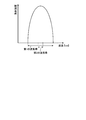
- the figure for demonstrating the wavelength and radiation intensity of the light irradiated from the light emitting diode in FIG. The figure for demonstrating the wavelength and radiation intensity of the light which reach the display part in FIG.
- Sectional drawing which shows an example of the display apparatus concerning Embodiment 2 of this invention
- Sectional drawing which shows an example of the display apparatus concerning Embodiment 3 of this invention
- FIG. 1 is a cross-sectional view showing an example of a display device according to Embodiment 1 of the present invention.
- FIG. 2 is a view for explaining the position of the display unit of the display device in the case where the display device in FIG. 1 is provided in the indoor unit of the air conditioner.
- FIG. 3 is a diagram for explaining the wavelength and the radiation intensity of light emitted from the light emitting diode in FIG.
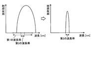
- FIG. 4 and FIG. 5 are diagrams for explaining the wavelength and radiation intensity of light reaching the display unit in FIG.
- the display device 100 according to the first embodiment of the present invention shown in FIG. 1 is provided, for example, in an indoor unit 200 of an air conditioner shown in FIG.
- the display device 100 is used to transmit information on the operating state of the air conditioner to the user.
- An example of the display device 100 is a lamp that indicates whether the air conditioner is operating.
- Another example of the display device 100 is a lamp that indicates that the air conditioner is performing a high load operation because the difference between the set temperature and the indoor temperature is large.
- the display device 100 includes a substrate 1a, a light emitting diode (LED) 2a provided on the substrate 1a, and a reflective material 4a provided on a path of light 3a emitted from the LED 2a.
- the reflector 4a reflects the light 3a.
- the reflective material 4a is an example of an irradiated part and a first reflective material.
- the display device 100 includes a display unit 5a provided on the path of the light 3a reflected by the reflective material 4a.
- the display unit 5a displays a color by transmitting the light 3a.
- the display device 100 includes a structure 6 a provided to surround the path of the light 3 a reflected by the reflective material 4 a. The structure 6a prevents the light 3a from leaking.
- the display device 100 includes a substrate 1 b, an LED 2 b provided on the substrate 1 b, and a reflector 4 b provided on a path of light 3 b emitted from the LED 2 b.
- the LED 2 b is an LED of the same color as the LED 2 a.
- the reflector 4b reflects the light 3b.
- the reflective material 4 b is an example of the irradiated part and the first reflective material.
- the display device 100 includes a display unit 5b provided on the path of the light 3b reflected by the reflective material 4b.
- the display unit 5 b displays a color by transmitting the light 3 b.
- the display device 100 includes a structure 6 b provided to surround the path of the light 3 b reflected by the reflector 4 b.
- the structure 6 b prevents the light 3 b from leaking.
- the housing 20 of the indoor unit 200, the display unit 5a and the display unit 5b constitute a design surface 21 of the indoor unit 200.
- the display unit 5a and the display unit 5b are provided on the front side of the housing 20 of the indoor unit 200 as shown in FIG.
- the reflective material 4a is a member obtained by, for example, kneading a coloring agent into a resin material and coloring it.
- the color colored by the reflective material 4a is selected according to the color of LED2a.
- the color of the LED 2a is selected in accordance with the color to be displayed on the display unit 5a. For example, when it is desired to cause the display unit 5a to display green, a green light emitting diode is used for the LED 2a. Then, the reflective material 4a is colored green by mixing a green colorant into the resin material.
- the reflective material 4a has a second absorptivity in a second wavelength band included in a first wavelength band which is a wavelength band of the light 3a shown in FIG.
- the second wavelength band is, for example, a wavelength band including a wavelength of 560 nm.
- the reflective material 4a has a reflectance in the second wavelength band of the light 3a shown in FIG. 3 when reflecting the light 3a emitted from the LED 2a is higher than the reflectance in wavelengths other than the second wavelength band It may be
- the reflective material 4 b is a member having the same configuration as the reflective material 4 a.
- the reflective material 4a and the reflective material 4b are polished so that the reflective surface 4x or the reflective surface 4y has a gloss.
- the display unit 5a and the display unit 5b are members that transmit the light 3a or the light 3b, and are configured by members that are not colored.
- the display unit 5a and the display unit 5b are formed of transparent plastic.
- the reflective material 4a and the display unit 5a may be disposed, and then the LED 2a and the structural body 6a may be disposed. After the display unit 5a and the LED 2a are disposed, the reflective material 4a and the structural body are disposed. 6a may be disposed, and the display unit 5a and the structural body 6a may be disposed after the LED 2a and the reflector 4a are disposed. Similarly, in the present embodiment, the reflective material 4b and the display unit 5b may be disposed, and then the LED 2b and the structural body 6b may be disposed. After the display unit 5b and the LED 2b are disposed, the reflective material 4b is disposed. The structure 6b may be disposed, and the display unit 5b and the structure 6b may be disposed after the LED 2b and the reflector 4b are disposed.
- the light 3 a emitted from the LED 2 a is reflected by the reflective material 4 a and reaches the display unit 5 a.
- the structure 6a prevents the light 3a from striking the part of the housing 20 other than the display unit 5a, for example. Since the reflecting member 4a is formed of the above-described colored member, light of wavelengths other than the second wavelength band among the light 3a incident on the reflecting surface 4x of the reflecting member 4a is the reflecting member 4a. Almost absorbed. On the other hand, of the light 3a of the light 3a incident on the reflection surface 4x of the reflection member 4a, the light of the wavelength of the second wavelength band is reflected by the reflection member 4a without being almost absorbed by the reflection member 4a.
- the light 3 a reaching the display unit 5 a is light in which the intensity of the wavelength of the second wavelength band is high and the intensity of wavelengths other than the second wavelength band is low.
- the left side of FIG. 4 shows the relationship between the wavelength of the light 3a emitted from the LED 2a and the radiation intensity.
- the light 3b emitted from the LED 2b is reflected by the reflective material 4b and reaches the display unit 5b.
- the structural body 6b it is possible to suppress that the light 3b strikes a part of the housing 20 other than the display unit 5b, for example, a part of the housing 20 is illuminated.
- the reflecting member 4b is formed of a member having the same configuration as the reflecting member 4a, light of wavelengths other than the second wavelength band among the light 3b incident on the reflecting surface 4y of the reflecting member 4b is a reflecting member Almost absorbed in 4b.
- the light of the wavelength of the second wavelength band among the light 3b incident on the reflecting surface 4y of the reflecting member 4b is reflected by the reflecting member 4b with hardly being absorbed by the reflecting member 4b. Therefore, as shown in the diagram showing the relationship between the wavelength on the left side of FIG. 4 and the radiation intensity and the diagram showing the relationship between the wavelength on the left side of FIG. 5 and the radiation intensity, Even in the case where there is an individual difference between the two, as shown in FIG. 5, the light 3b reaching the display unit 5b has a strong wavelength intensity of the second wavelength band and an intensity of wavelengths other than the second wavelength band It becomes weak light.
- FIGS. 4 and 5 shows the relationship between the wavelength of the light 3 b emitted from the LED 2 b and the radiation intensity.
- the cause of the variation of the displayed color due to individual differences of the light emitting diodes is, as shown in FIGS. 4 and 5, components of wavelengths other than the second wavelength band. is there.
- the light 3a reaching the display unit 5a has a high intensity of the wavelength of the second wavelength band of the light 3a and a weak intensity of the wavelengths other than the second wavelength band of the light 3a.
- the light 3 b reaching the display unit 5 b also has high intensity in the wavelength of the second wavelength band and weak intensity in wavelengths other than the second wavelength band.
- the display unit 5a and the display unit 5b the light 3a or the light 3b with strong intensity of the wavelength in the second wavelength band is transmitted, so the color displayed by the display unit 5a and the display unit 5b is the second wavelength band. It can be made a color corresponding to the wavelength. That is, the color which the display part 5a and the display part 5b display can be set with the reflecting material 4a and the reflecting material 4b.
- the display device 100 includes two display units each including a substrate, an LED, a reflective material, a display unit, and a structure, but three or more display units are provided. May be provided.
- the display unit 5a and the display unit 5b are formed of non-colored members different from the reflective material 4a and the reflective material 4b.
- the absorptivity and reflectance of the display unit 5a and the display unit 5b are not the same as the absorptivity and reflectance of the reflector 4a and the reflector 4b.
- a fluorescent lamp in a room where an indoor unit is installed The reflected lights from the display unit 5a and the display unit 5b generated by disturbance light from the light source do not become light in which the intensity of the wavelength in the second wavelength band described above is strong.
- the display unit 5a and the display unit 5b it is possible to clearly indicate to the user the difference in color displayed when the LED 2a and the LED 2b are on and when the LED 2a and the LED 2b are off.
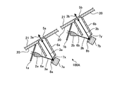
- FIG. 6 is a cross-sectional view showing an example of a display device according to Embodiment 2 of the present invention.
- the display device 100A according to the second embodiment of the present invention does not include the reflector 4a and the reflector 4b, but includes the reflector 7a, the translucent member 8a, the reflector 7b, and the translucent member 8b.
- This embodiment differs from the first embodiment described above. Descriptions of configurations and operations overlapping with those of the first embodiment will be omitted, and different configurations and operations will be described below.
- a display device 100A according to a second embodiment of the present invention shown in FIG. 6 includes a substrate 1a, an LED 2a, and a reflector 7a provided on a path of light 3a emitted from the LED 2a.
- the reflector 7a reflects the light 3a.
- the display device 100A includes a translucent member 8a provided on the reflection surface 7x of the reflection member 7a.
- the reflective material 7a and the translucent member 8a are an example of a to-be-irradiated part.
- the reflector 7a is an example of a second reflector.
- the translucent member 8a is attached to the reflection surface 7x of the reflection member 7a.
- the display device 100A includes a display unit 5a provided on the path of the light 3a reflected by the reflective material 7a.
- the display unit 5a displays a color by transmitting the light 3a.
- the display device 100A includes a structure 6a provided to surround the path of the light 3a reflected by the reflective material 7a. The structure 6a
- the display device 100A includes a substrate 1b, an LED 2b, and a reflector 7b provided on a path of light 3b emitted from the LED 2b.
- the reflector 7b reflects the light 3b.
- the display device 100A includes a translucent member 8b provided on the reflective surface 7y of the reflective member 7b.
- the reflective material 7 b and the translucent member 8 b are an example of a portion to be irradiated.
- the reflector 7 b is an example of a second reflector.
- the translucent member 8b is attached to the reflecting surface 7y of the reflecting member 7b.
- the display device 100A includes a display unit 5b provided on the path of the light 3b reflected by the reflective material 7b.
- the display unit 5 b displays a color by transmitting the light 3 b.
- the display device 100A includes a structure 6b provided to surround the path of the light 3b reflected by the reflector 7b.
- the structure 6 b prevents the light 3 b from leaking.
- the reflectors 7a and 7b are, for example, mirrors that reflect the light 3a or the light 3b.
- the translucent member 8a is a colored translucent member such as a color film. The color of the translucent member 8a is selected in accordance with the color of the LED 2a. The color of the LED 2a is selected in accordance with the color to be displayed on the display unit 5a. For example, when it is desired to cause the display unit 5a to display red, a red light emitting diode is used for the LED 2a.
- the translucent member 8a is red. For example, when the LED 2a is a red light emitting diode, the translucent member 8a is a red color film.
- the translucent member 8a When the translucent member 8a absorbs the light 3a emitted from the LED 2a, the absorptivity in the second wavelength band included in the first wavelength band which is the wavelength band of the light 3a shown in FIG.
- the semitransparent member 8a has a higher transmittance in the second wavelength band of the light 3a shown in FIG. 3 when transmitting the light 3a emitted from the LED 2a than in the wavelengths other than the second wavelength band. It may be one.
- the translucent member 8 b is a member having the same configuration as the translucent member 8 a.
- the LED 2a and the structure 6a may be arranged after arranging the reflective member 7a, the semitransparent member 8a and the display part 5a, and after arranging the display part 5a and the LED 2a, reflection may be performed.
- the material 7a, the translucent member 8a and the structure 6a may be disposed, or the LED 2a, the reflector 7a and the translucent member 8a may be disposed, and then the display unit 5a and the structure 6a may be disposed.
- the LED 2b and the structural body 6b may be disposed after the reflecting member 7b, the semitransparent member 8b, and the display 5b are disposed, and the display 5b and the LED 2b are disposed.
- the reflector 7b, the translucent member 8b and the structure 6b may be disposed, and after the LED 2b, the reflector 7b and the translucent member 8b are disposed, the display portion 5b and the structure 6b are disposed. You may
- the light 3a emitted from the LED 2a is reflected by the reflective material 7a and reaches the display unit 5a. Since the translucent member 8a with a color such as the above-mentioned color film is provided on the reflecting surface 7x of the reflecting member 7a, the wavelength of the light 3a incident on the translucent member 8a other than the second wavelength band Is almost absorbed by the translucent member 8a.
- the light of the wavelength of the second wavelength band is reflected by the reflective member 7a with hardly absorbed by the semitransparent member 8a, and is reflected by the reflective member 7a Even after being reflected, it is hardly absorbed by the translucent member 8a and is emitted from the translucent member 8a.
- the light 3 a reaching the display unit 5 a is light in which the intensity of the wavelength of the second wavelength band is high and the intensity of wavelengths other than the second wavelength band is low.
- the light 3 b emitted from the LED 2 b is reflected by the reflective material 7 b and reaches the display unit 5 b. Since the semitransparent member 8b having the same configuration as the semitransparent member 8a is provided on the reflection surface 7y of the reflective member 7b, the light 3b of light having a wavelength other than the second wavelength band incident on the semitransparent member 8b Light is mostly absorbed by the translucent member 8b.
- the light of the wavelength of the second wavelength band is reflected by the reflective member 7b with hardly absorbed by the semitransparent member 8b, and is reflected by the reflective member 7b Even after being reflected, it is hardly absorbed by the translucent member 8b and emitted from the translucent member 8b. Therefore, as shown in the diagram showing the relationship between the wavelength on the left side of FIG. 4 and the radiation intensity and the diagram showing the relationship between the wavelength on the left side of FIG. 5 and the radiation intensity, Even in the case where there is an individual difference between the two, as shown in FIG. 5, the light 3b reaching the display unit 5b has a strong wavelength intensity of the second wavelength band and an intensity of wavelengths other than the second wavelength band It becomes weak light.
- the light 3a reaching the display unit 5a has a high intensity of the wavelength of the second wavelength band of the light 3a and a weak intensity of the wavelengths other than the second wavelength band of the light 3a.
- the light 3 b reaching the display unit 5 b also has high intensity in the wavelength of the second wavelength band and weak intensity in wavelengths other than the second wavelength band.
- the same effect as that of the first embodiment described above can be obtained.
- the light 3a or the light 3b is reflected by a mirror, so that the reflectance at the time of reflecting the light 3a or the light 3b is high compared to the first embodiment described above. can do.
- the display device 100A includes two display units each including a substrate, an LED, a reflector, a semitransparent member, a display unit, and a structure.
- One or more display units may be provided.
- the display unit 5a and the display unit 5b are configured by non-colored members which are different from the translucent member 8a and the translucent member 8b. Thereby, the same effect as that of the first embodiment described above can be obtained.
- the light emitted from the LED is reflected by the reflective material while being transmitted by the semitransparent member, and reaches the display portion.
- the LED 2a, the semitransparent member 8a, and the display 5a are provided on a straight line without providing the reflector 7a, and the light emitted from the LED 2a to reach the display 5a.
- the path 3a may be linear.
- FIG. 7 is a diagram for explaining a modification of the display device according to the second embodiment of the present invention. In this case, since it is not necessary to provide the reflective material 7a, the number of parts can be reduced. It is suitable, for example, when the display device 100A is provided, for example, when there is room in the internal space of the housing 20 of the indoor unit 200 shown in FIG.
- FIG. 8 is a cross-sectional view showing an example of a display device according to Embodiment 3 of the present invention.
- the display device 100B according to the third embodiment of the present invention does not include the reflector 4a, the structure 6a, the reflector 4b, and the structure 6b, and the reflector 9a, the reflector 10a, the reflector 9b, and the reflector 10b. Is different from the first embodiment described above. Descriptions of configurations and operations overlapping with those of the first embodiment will be omitted, and different configurations and operations will be described below.
- a display device 100B according to the third embodiment of the present invention shown in FIG. 8 includes a substrate 1a, an LED 2a, and a reflector 9a provided on a path of light 3a emitted from the LED 2a.
- the reflector 9a reflects the light 3a.
- the display device 100B includes a reflector 10a provided on the path of the light 3a reflected by the reflector 9a.
- the reflective material 10 a causes the light 3 a to reach the display unit 5 a by reflecting the light 3 a at least once.
- the reflector 10a prevents the light 3a from leaking.
- the display device 100B includes the display unit 5a that displays a color by transmitting the light 3a.
- the reflective material 9a and the reflective material 10a are an example of a to-be-irradiated part.
- the reflector 9a is an example of a third reflector.
- the reflector 10a is an example of a fourth reflector.
- the display device 100B includes a substrate 1b, an LED 2b, and a reflector 9b provided on a path of light 3b emitted from the LED 2b.
- the reflector 9b reflects the light 3b.
- the display device 100B includes a reflector 10b provided on the path of the light 3b reflected by the reflector 9b.
- the reflective material 10 b causes the light 3 b to reach the display unit 5 b by reflecting the light 3 b at least once.
- the reflector 10b prevents the light 3b from leaking.
- the display device 100B includes a display unit 5b that displays a color by transmitting the light 3b.
- the reflective material 9 b and the reflective material 10 b are an example of an irradiated part.
- the reflector 9 b is an example of a third reflector.
- the reflector 10 b is an example of a fourth reflector.
- the reflective material 9a is a colored member obtained by, for example, kneading a coloring agent into a resin material.
- the color to be colored in the reflective material 9a is selected in accordance with the color of the LED 2a.
- the color of the LED 2a is selected in accordance with the color to be displayed on the display unit 5a. For example, when it is desired to cause the display unit 5a to display blue, a blue light emitting diode is used for the LED 2a.
- the reflective material 9a is colored in blue by mixing a blue colorant into the resin material.
- the reflective material 9a has a second absorptivity in a second wavelength band included in a first wavelength band which is a wavelength band of the light 3a shown in FIG.
- Reflecting material 9a has a reflectance in the second wavelength band of light 3a shown in FIG. 3 when reflecting light 3a emitted from LED 2a is higher than the reflectance in wavelengths other than the second wavelength band It may be
- the reflector 9 b is a member having the same configuration as the reflector 9 a.
- the reflective material 9 a and the reflective material 9 b are polished so that the reflective surface 9 x or the reflective surface 9 y has a gloss.
- the reflective material 10a is, for example, a member in which a coloring material is kneaded into a resin material and colored.
- the reflective material 10a is colored blue by mixing a blue colorant into the resin material.
- the absorptivity in the second wavelength band included in the first wavelength band that is the wavelength band of the light 3a shown in FIG. 3 is a wavelength other than the second wavelength band Lower than the absorption rate in The reflective material 10a may have a higher reflectance in the second wavelength band of the light 3a shown in FIG. 3 when reflecting the light 3a than in the wavelengths other than the second wavelength band. .
- the reflective material 10 b is a member having the same configuration as the reflective material 10 a.
- the reflective material 10a and the reflective material 10b are also polished so that the reflective surface 10x or the reflective surface 10y has a gloss.
- the reflective material 9a, the reflective material 9b, the reflective material 10a, and the reflective material 10b may be made of a colored aluminum tape, or may be made of aluminum and a color film.
- the reflective material 9a and the display unit 5a may be disposed, and then the LED 2a and the reflective material 10a may be disposed. After the display unit 5a and the LED 2a are disposed, the reflective material 9a and the reflective material are disposed. 10a may be disposed, and after the LED 2a and the reflector 9a are disposed, the display unit 5a and the reflector 10a may be disposed. Similarly, in the present embodiment, the reflective material 9b and the display unit 5b may be disposed, and then the LED 2b and the reflective material 10b may be disposed. After the display unit 5b and the LED 2b are disposed, the reflective material 9b is disposed. The reflective material 10b may be disposed, and the display unit 5b and the reflective material 10b may be disposed after the LED 2b and the reflective material 9b are disposed.
- the light 3 a emitted from the LED 2 a is reflected by the reflective material 9 a and the reflective material 10 a and reaches the display unit 5 a.
- the reflective material 10 a prevents the light 3 a from hitting the part other than the display unit 5 a, for example, a part of the housing 20 to suppress the light from part of the housing 20. Since the reflective material 9a and the reflective material 10a are constituted by the colored members described above, the second of the light 3a of the light 3a incident on the reflective surface 9x of the reflective material 9a and the reflective surface 10x of the reflective material 10a. Light of wavelengths other than the wavelength band is mostly absorbed by the reflectors 9a and 10a.
- the light of the wavelength of the second wavelength band is almost absorbed by the reflection material 9a and the reflection material 10a.
- the light is reflected by the reflector 9a and the reflector 10a.
- the light 3 a reaching the display unit 5 a is light in which the intensity of the wavelength of the second wavelength band is high and the intensity of wavelengths other than the second wavelength band is low.
- the light 3 b emitted from the LED 2 b is reflected by the reflectors 9 b and 10 b and reaches the display unit 5 b.
- the reflective material 10 b prevents the light 3 b from hitting the part other than the display unit 5 b, for example, a part of the housing 20 to suppress the light from part of the housing 20. Since the reflector 9b is constituted by a member having the same configuration as the reflector 9a and the reflector 10b is constituted by a member having the same configuration as the reflector 10a, the reflection surface 9y of the reflector 9b and the reflection surface of the reflector 10b Of the light 3b incident on 10y, light of wavelengths other than the second wavelength band is mostly absorbed by the reflectors 9b and 10b.
- the light of the wavelength of the second wavelength band among the light 3b incident on the reflection surface 9y of the reflection material 9b and the reflection surface 10y of the reflection material 10b is almost absorbed by the reflection material 9b and the reflection material 10b Without reflection, the light is reflected by the reflectors 9b and 10b. Therefore, as shown in the diagram showing the relationship between the wavelength on the left side of FIG. 4 and the radiation intensity and the diagram showing the relationship between the wavelength on the left side of FIG. 5 and the radiation intensity, Even in the case where there is an individual difference between the two, as shown in FIG. 5, the light 3b reaching the display unit 5b has a strong wavelength intensity of the second wavelength band and an intensity of wavelengths other than the second wavelength band It becomes weak light.
- the light 3a reaching the display unit 5a has a high intensity of the wavelength of the second wavelength band of the light 3a and a weak intensity of the wavelengths other than the second wavelength band of the light 3a.
- the light 3 b reaching the display unit 5 b also has high intensity in the wavelength of the second wavelength band and weak intensity in wavelengths other than the second wavelength band.
- the light 3a or the light 3b emitted from the LED 2a or the LED 2b is at least twice reflected by the reflector 9a or 9b and the reflector 10a or 10b, and the display unit
- the light 3a or the light 3b reaching the display 5a or 5b is compared with the case where the light 3 is reflected only once and reaches the display 5a or 5b.
- the intensity of the wavelength other than the two wavelength bands can be the light 3a or the light 3b.
- the display device 100B includes two display units each including a substrate, an LED, two reflectors, and a display unit.
- the display device 100B includes three or more display units. It may be one.
- the display unit 5a and the display unit 5b are configured of the reflective material 9a and the reflective material 10a, or a non-colored member different from the reflective material 9b and the reflective material 10b. Thereby, the same effect as that of the first embodiment described above can be obtained.
- the LEDs used in the display device are not limited to single color LEDs such as red LEDs, green LEDs and blue LEDs, and may have a somewhat wide wavelength band such as white LEDs.
- the configuration shown in the above embodiment shows an example of the contents of the present invention, and can be combined with another known technique, and one of the configurations is possible within the scope of the present invention. It is also possible to omit and change parts.
Landscapes
- Physics & Mathematics (AREA)
- General Physics & Mathematics (AREA)
- Engineering & Computer Science (AREA)
- Theoretical Computer Science (AREA)
- Geometry (AREA)
- Illuminated Signs And Luminous Advertising (AREA)
- Air Filters, Heat-Exchange Apparatuses, And Housings Of Air-Conditioning Units (AREA)
- Air Conditioning Control Device (AREA)
- Devices For Indicating Variable Information By Combining Individual Elements (AREA)
- Led Device Packages (AREA)
Abstract
La présente invention concerne un dispositif d'affichage (100) qui comprend des diodes électroluminescentes (2a, 2b) et des réflecteurs (4a, 4b). Lors de l'absorption de la lumière (3a, 3b) émise par les diodes électroluminescentes (2a, 2b), l'absorption dans une seconde plage de longueurs d'onde comprise dans une première plage de longueurs d'onde qui est la plage de longueurs d'onde de la lumière (3a) est inférieure à l'absorption dans les longueurs d'onde à l'extérieur de la seconde plage de longueurs d'onde. Le dispositif d'affichage (100) comprend également des parties d'affichage (5a, 5b) qui transmettent la lumière (3a, 3b) réfléchie par les réflecteurs (4a, 4b).
Priority Applications (2)
| Application Number | Priority Date | Filing Date | Title |
|---|---|---|---|
| PCT/JP2017/035686 WO2019064562A1 (fr) | 2017-09-29 | 2017-09-29 | Dispositif d'affichage et climatiseur |
| JP2019544160A JP7023290B2 (ja) | 2017-09-29 | 2017-09-29 | 表示装置および空気調和機 |
Applications Claiming Priority (1)
| Application Number | Priority Date | Filing Date | Title |
|---|---|---|---|
| PCT/JP2017/035686 WO2019064562A1 (fr) | 2017-09-29 | 2017-09-29 | Dispositif d'affichage et climatiseur |
Publications (1)
| Publication Number | Publication Date |
|---|---|
| WO2019064562A1 true WO2019064562A1 (fr) | 2019-04-04 |
Family
ID=65901098
Family Applications (1)
| Application Number | Title | Priority Date | Filing Date |
|---|---|---|---|
| PCT/JP2017/035686 Ceased WO2019064562A1 (fr) | 2017-09-29 | 2017-09-29 | Dispositif d'affichage et climatiseur |
Country Status (2)
| Country | Link |
|---|---|
| JP (1) | JP7023290B2 (fr) |
| WO (1) | WO2019064562A1 (fr) |
Citations (7)
| Publication number | Priority date | Publication date | Assignee | Title |
|---|---|---|---|---|
| JPS5732974U (fr) * | 1980-07-30 | 1982-02-20 | ||
| JPH0366105U (fr) * | 1989-10-31 | 1991-06-27 | ||
| US6004001A (en) * | 1996-09-12 | 1999-12-21 | Vdo Adolf Schindling Ag | Illumination for a display |
| JP2002139630A (ja) * | 2000-10-31 | 2002-05-17 | Alps Electric Co Ltd | 導光板およびその製造方法、面発光装置並びに液晶表示装置 |
| JP2005148181A (ja) * | 2003-11-12 | 2005-06-09 | Sharp Corp | 表示装置とそれを備えた空気調和機 |
| JP2006285053A (ja) * | 2005-04-04 | 2006-10-19 | Calsonic Kansei Corp | 可変表示構造 |
| JP2013170787A (ja) * | 2012-02-22 | 2013-09-02 | Mitsubishi Electric Corp | 空気調和機の室内機 |
Family Cites Families (2)
| Publication number | Priority date | Publication date | Assignee | Title |
|---|---|---|---|---|
| JPH05234409A (ja) * | 1992-02-18 | 1993-09-10 | Naka Ind Ltd | 照明装置 |
| JP2000302347A (ja) | 1999-04-15 | 2000-10-31 | Toshiba Corp | 表示装置および押ボタンスイッチ |
-
2017
- 2017-09-29 WO PCT/JP2017/035686 patent/WO2019064562A1/fr not_active Ceased
- 2017-09-29 JP JP2019544160A patent/JP7023290B2/ja not_active Expired - Fee Related
Patent Citations (7)
| Publication number | Priority date | Publication date | Assignee | Title |
|---|---|---|---|---|
| JPS5732974U (fr) * | 1980-07-30 | 1982-02-20 | ||
| JPH0366105U (fr) * | 1989-10-31 | 1991-06-27 | ||
| US6004001A (en) * | 1996-09-12 | 1999-12-21 | Vdo Adolf Schindling Ag | Illumination for a display |
| JP2002139630A (ja) * | 2000-10-31 | 2002-05-17 | Alps Electric Co Ltd | 導光板およびその製造方法、面発光装置並びに液晶表示装置 |
| JP2005148181A (ja) * | 2003-11-12 | 2005-06-09 | Sharp Corp | 表示装置とそれを備えた空気調和機 |
| JP2006285053A (ja) * | 2005-04-04 | 2006-10-19 | Calsonic Kansei Corp | 可変表示構造 |
| JP2013170787A (ja) * | 2012-02-22 | 2013-09-02 | Mitsubishi Electric Corp | 空気調和機の室内機 |
Also Published As
| Publication number | Publication date |
|---|---|
| JPWO2019064562A1 (ja) | 2020-05-28 |
| JP7023290B2 (ja) | 2022-02-21 |
Similar Documents
| Publication | Publication Date | Title |
|---|---|---|
| CN104238248B (zh) | 光源模块与投影装置 | |
| EP3309610B1 (fr) | Source de lumière laser bichromatique | |
| CN108761981B (zh) | 投影机 | |
| US9279987B2 (en) | Optical element and lighting device | |
| JP6144410B2 (ja) | 発光装置及び投影システム | |
| US8388175B2 (en) | Lighting device | |
| JP2010536138A (ja) | 照明装置 | |
| US8801192B2 (en) | Light source module and projector using the same | |
| JP2014533876A5 (fr) | ||
| JP6206870B2 (ja) | 光学表示装置 | |
| JP2011007995A (ja) | スクリーンおよびプロジェクションシステム | |
| JP2017508250A (ja) | 遠隔ダウンコンバータを含む光学デバイス | |
| JP2021176014A (ja) | 表示装置 | |
| US20090046459A1 (en) | Lighting device | |
| CN105339827A (zh) | 照明设备 | |
| CN110297384B (zh) | 一种用于投影的光源 | |
| JP5119379B2 (ja) | 面照明光源装置及び面照明装置 | |
| CN111624840A (zh) | 一种光源装置以及投影显示设备 | |
| JP2019194643A (ja) | 表示装置 | |
| CN210072303U (zh) | 一种用于投影的光源 | |
| JP7023290B2 (ja) | 表示装置および空気調和機 | |
| JP3352989B2 (ja) | 車両用信号灯具 | |
| JP2010536137A (ja) | 照明デバイス | |
| CN217423130U (zh) | 一种天空灯 | |
| US10443813B2 (en) | Lens with slits |
Legal Events
| Date | Code | Title | Description |
|---|---|---|---|
| 121 | Ep: the epo has been informed by wipo that ep was designated in this application |
Ref document number: 17926878 Country of ref document: EP Kind code of ref document: A1 |
|
| ENP | Entry into the national phase |
Ref document number: 2019544160 Country of ref document: JP Kind code of ref document: A |
|
| NENP | Non-entry into the national phase |
Ref country code: DE |
|
| 122 | Ep: pct application non-entry in european phase |
Ref document number: 17926878 Country of ref document: EP Kind code of ref document: A1 |