WO2019069934A1 - プログラム作成装置、溶接システム、及びプログラム作成方法 - Google Patents
プログラム作成装置、溶接システム、及びプログラム作成方法 Download PDFInfo
- Publication number
- WO2019069934A1 WO2019069934A1 PCT/JP2018/036903 JP2018036903W WO2019069934A1 WO 2019069934 A1 WO2019069934 A1 WO 2019069934A1 JP 2018036903 W JP2018036903 W JP 2018036903W WO 2019069934 A1 WO2019069934 A1 WO 2019069934A1
- Authority
- WO
- WIPO (PCT)
- Prior art keywords
- welding
- program
- selected surface
- unit
- product model
- Prior art date
- Legal status (The legal status is an assumption and is not a legal conclusion. Google has not performed a legal analysis and makes no representation as to the accuracy of the status listed.)
- Ceased
Links
Images




Classifications
-
- B—PERFORMING OPERATIONS; TRANSPORTING
- B23—MACHINE TOOLS; METAL-WORKING NOT OTHERWISE PROVIDED FOR
- B23K—SOLDERING OR UNSOLDERING; WELDING; CLADDING OR PLATING BY SOLDERING OR WELDING; CUTTING BY APPLYING HEAT LOCALLY, e.g. FLAME CUTTING; WORKING BY LASER BEAM
- B23K9/00—Arc welding or cutting
- B23K9/095—Monitoring or automatic control of welding parameters
- B23K9/0953—Monitoring or automatic control of welding parameters using computing means
-
- G—PHYSICS
- G05—CONTROLLING; REGULATING
- G05B—CONTROL OR REGULATING SYSTEMS IN GENERAL; FUNCTIONAL ELEMENTS OF SUCH SYSTEMS; MONITORING OR TESTING ARRANGEMENTS FOR SUCH SYSTEMS OR ELEMENTS
- G05B19/00—Program-control systems
- G05B19/02—Program-control systems electric
- G05B19/18—Numerical control [NC], i.e. automatically operating machines, in particular machine tools, e.g. in a manufacturing environment, so as to execute positioning, movement or co-ordinated operations by means of program data in numerical form
- G05B19/4097—Numerical control [NC], i.e. automatically operating machines, in particular machine tools, e.g. in a manufacturing environment, so as to execute positioning, movement or co-ordinated operations by means of program data in numerical form characterised by using design data to control NC machines, e.g. CAD/CAM
-
- B—PERFORMING OPERATIONS; TRANSPORTING
- B23—MACHINE TOOLS; METAL-WORKING NOT OTHERWISE PROVIDED FOR
- B23K—SOLDERING OR UNSOLDERING; WELDING; CLADDING OR PLATING BY SOLDERING OR WELDING; CUTTING BY APPLYING HEAT LOCALLY, e.g. FLAME CUTTING; WORKING BY LASER BEAM
- B23K26/00—Working by laser beam, e.g. welding, cutting or boring
-
- B—PERFORMING OPERATIONS; TRANSPORTING
- B23—MACHINE TOOLS; METAL-WORKING NOT OTHERWISE PROVIDED FOR
- B23K—SOLDERING OR UNSOLDERING; WELDING; CLADDING OR PLATING BY SOLDERING OR WELDING; CUTTING BY APPLYING HEAT LOCALLY, e.g. FLAME CUTTING; WORKING BY LASER BEAM
- B23K26/00—Working by laser beam, e.g. welding, cutting or boring
- B23K26/08—Devices involving relative movement between laser beam and workpiece
-
- B—PERFORMING OPERATIONS; TRANSPORTING
- B23—MACHINE TOOLS; METAL-WORKING NOT OTHERWISE PROVIDED FOR
- B23K—SOLDERING OR UNSOLDERING; WELDING; CLADDING OR PLATING BY SOLDERING OR WELDING; CUTTING BY APPLYING HEAT LOCALLY, e.g. FLAME CUTTING; WORKING BY LASER BEAM
- B23K26/00—Working by laser beam, e.g. welding, cutting or boring
- B23K26/20—Bonding
- B23K26/21—Bonding by welding
-
- B—PERFORMING OPERATIONS; TRANSPORTING
- B23—MACHINE TOOLS; METAL-WORKING NOT OTHERWISE PROVIDED FOR
- B23K—SOLDERING OR UNSOLDERING; WELDING; CLADDING OR PLATING BY SOLDERING OR WELDING; CUTTING BY APPLYING HEAT LOCALLY, e.g. FLAME CUTTING; WORKING BY LASER BEAM
- B23K26/00—Working by laser beam, e.g. welding, cutting or boring
- B23K26/20—Bonding
- B23K26/21—Bonding by welding
- B23K26/22—Spot welding
-
- B—PERFORMING OPERATIONS; TRANSPORTING
- B23—MACHINE TOOLS; METAL-WORKING NOT OTHERWISE PROVIDED FOR
- B23K—SOLDERING OR UNSOLDERING; WELDING; CLADDING OR PLATING BY SOLDERING OR WELDING; CUTTING BY APPLYING HEAT LOCALLY, e.g. FLAME CUTTING; WORKING BY LASER BEAM
- B23K9/00—Arc welding or cutting
- B23K9/04—Welding for other purposes than joining, e.g. built-up welding
- B23K9/044—Built-up welding on three-dimensional surfaces
-
- B—PERFORMING OPERATIONS; TRANSPORTING
- B23—MACHINE TOOLS; METAL-WORKING NOT OTHERWISE PROVIDED FOR
- B23K—SOLDERING OR UNSOLDERING; WELDING; CLADDING OR PLATING BY SOLDERING OR WELDING; CUTTING BY APPLYING HEAT LOCALLY, e.g. FLAME CUTTING; WORKING BY LASER BEAM
- B23K9/00—Arc welding or cutting
- B23K9/095—Monitoring or automatic control of welding parameters
- B23K9/0956—Monitoring or automatic control of welding parameters using sensing means, e.g. optical
-
- B—PERFORMING OPERATIONS; TRANSPORTING
- B23—MACHINE TOOLS; METAL-WORKING NOT OTHERWISE PROVIDED FOR
- B23K—SOLDERING OR UNSOLDERING; WELDING; CLADDING OR PLATING BY SOLDERING OR WELDING; CUTTING BY APPLYING HEAT LOCALLY, e.g. FLAME CUTTING; WORKING BY LASER BEAM
- B23K9/00—Arc welding or cutting
- B23K9/12—Automatic feeding or moving of electrodes or work for spot or seam welding or cutting
- B23K9/127—Means for tracking lines during arc welding or cutting
- B23K9/1272—Geometry oriented, e.g. beam optical trading
- B23K9/1274—Using non-contact, optical means, e.g. laser means
-
- G—PHYSICS
- G05—CONTROLLING; REGULATING
- G05B—CONTROL OR REGULATING SYSTEMS IN GENERAL; FUNCTIONAL ELEMENTS OF SUCH SYSTEMS; MONITORING OR TESTING ARRANGEMENTS FOR SUCH SYSTEMS OR ELEMENTS
- G05B19/00—Program-control systems
- G05B19/02—Program-control systems electric
- G05B19/18—Numerical control [NC], i.e. automatically operating machines, in particular machine tools, e.g. in a manufacturing environment, so as to execute positioning, movement or co-ordinated operations by means of program data in numerical form
- G05B19/401—Numerical control [NC], i.e. automatically operating machines, in particular machine tools, e.g. in a manufacturing environment, so as to execute positioning, movement or co-ordinated operations by means of program data in numerical form characterised by control arrangements for measuring, e.g. calibration and initialisation, measuring workpiece for machining purposes
-
- G—PHYSICS
- G06—COMPUTING OR CALCULATING; COUNTING
- G06T—IMAGE DATA PROCESSING OR GENERATION, IN GENERAL
- G06T7/00—Image analysis
- G06T7/0002—Inspection of images, e.g. flaw detection
- G06T7/0004—Industrial image inspection
-
- G—PHYSICS
- G05—CONTROLLING; REGULATING
- G05B—CONTROL OR REGULATING SYSTEMS IN GENERAL; FUNCTIONAL ELEMENTS OF SUCH SYSTEMS; MONITORING OR TESTING ARRANGEMENTS FOR SUCH SYSTEMS OR ELEMENTS
- G05B2219/00—Program-control systems
- G05B2219/30—Nc systems
- G05B2219/45—Nc applications
- G05B2219/45104—Lasrobot, welding robot
Definitions
- the present invention relates to a program creation apparatus and the like for creating a welding program for performing spot welding on a plurality of plate-like works (sheet metals) by control of a welding robot.
- image data of a product model is created, and this is displayed (displayed on a screen) on a display unit such as a display in the program creation device.
- a display unit such as a display in the program creation device.
- set welds in the product model is created.
- a welding program including motion-related data of the welding robot related to the set welding point is created.
- the created welding program is sent to an NC device that controls the welding robot.
- Patent Document 1 As prior art related to the present invention, there are those shown in Patent Document 1 to Patent Document 3.
- a welding location can be set, without checking the back side of a welding location in a product model.
- a welding program for spot welding a plurality of workpieces overlap at the welding location, and in a normal state, it may not be possible to see the back side of the welding location in the product model. Therefore, in the latter case, it is necessary to appropriately set the welding portion while rotating the product model to confirm that there is no hole or notch on the back side of the welding portion. Therefore, it may not be possible to sufficiently increase the efficiency of the work of creating the welding program.
- an object of the present invention is to provide a program creation apparatus or the like having a novel configuration that can solve the above-mentioned problems.
- the first aspect of the present invention is used in a welding system for producing a product by performing spot welding on a plurality of overlapping plate-like works (sheet metals), and for a plurality of works by control of a welding robot.
- a program creation device for creating a welding program for performing spot welding comprising: a display unit for displaying an image (screen display); and image data of a product model (a model defined by the actual shape of the product) And an image generation unit for displaying a product model (an image of the product model) on the display unit, a display control unit for semi-transparentizing a workpiece including a selected selected surface of the product model, and a workpiece including a selected surface Weld position setting section for setting a weld position (workpiece weld position) in the product model (selected surface) in a semitransparent state of
- a program creation unit that creates the welding program containing the relevant data of the welding robots is that having a.
- the image generation unit generates image data of a product model and causes the display unit to display the product model.
- the display control unit semi-transparents the workpiece including the selected surface in the product model.
- a welding location setting part sets a welding location in a selection side (a selection side of a product model) in the state where the work containing a selection side was made translucent.
- the program creation unit creates the welding program including the related data of the welding robot related to the set welding point.
- the welding point is set on the selected surface.
- the welding portion while avoiding holes or notches.
- a welding system for spot welding a plurality of workpieces in a welding system for producing a product by performing spot welding on a plurality of overlapping plate-like workpieces (sheet metals)
- a program creation device for creating a welding program for spot welding a plurality of workpieces, and an NC device for controlling the welding robot based on the welding program.
- the same action as the action according to the first aspect of the present invention is exerted.
- the third aspect of the present invention is used in producing a product by performing spot welding on a plurality of overlapping plate-like works (sheet metals), and a spot on a plurality of works by control of a welding robot
- a program creating method for creating a welding program for performing welding generating image data of a product model (a model defined by an actual shape of a product), and displaying the product model (image of the product model) on a display unit Display (display on screen), make the workpiece including the selected surface selected in the product model semi-transparent, and set the weld location (the weld location of the workpiece) on the selected surface (selected surface of the product model) Creating the welding program including related data of the welding robot related to the welding position.
- the welding portion is set on the selected surface in a state in which the work including the selected surface is translucent.
- the efficiency of the creating operation can be sufficiently enhanced.
- FIG. 1 is a schematic perspective view of a welding system according to an embodiment of the present invention.
- FIG. 2A is a perspective view of a product to be manufactured of a welding system according to an embodiment of the present invention.
- FIG. 2B is a bottom perspective view of a product that is the object of fabrication of a welding system according to an embodiment of the present invention.
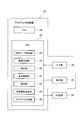
- FIG. 3 is a control block diagram of the program creation device according to the embodiment of the present invention.
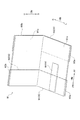
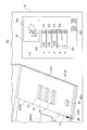
- FIG. 4 is a view showing a view screen of a display unit displaying a product model.
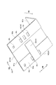
- FIG. 5 is a view showing a view screen of a display unit displayed so as to make a workpiece including a selection surface translucent.
- FIG. 1 is a schematic perspective view of a welding system according to an embodiment of the present invention.
- FIG. 2A is a perspective view of a product to be manufactured of a welding system according to an embodiment of the present invention.
- FIG. 2B is a bottom perspective view of a product that is the object
- FIG. 6 is an enlarged view of a view screen in which a parameter setting area is displayed together with a product model.
- FIG. 7 is an enlarged view of a view screen in which setting values are input to a plurality of setting items in the parameter setting area.
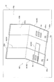
- FIG. 8 is a view showing a view screen on which a product model including a plurality of set welding points is displayed.
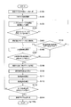
- FIG. 9 is a flow chart for explaining the operation of the embodiment of the present invention.
- the "X-axis direction” is one in the horizontal direction, that is, the left-right direction.
- the “Y-axis direction” is one in the horizontal direction, that is, the front-rear direction.
- the “Z-axis direction” is the vertical direction (vertical direction). In the figure, “FF” is forward, “FR” is backward, “L” is left, “R” is right, “U” is upward, and “D” is downward. Each point in the direction.
- a welding system 10 performs spot welding on a plurality of overlapping plate-like works (sheet metals) W to form a product M. It is a system to produce.
- summary of the welding system 10 which concerns on embodiment of this invention is as follows.
- the welding system 10 includes a mounting table 12 on which a plurality of overlapping plate-like works W are placed, and the mounting table 12 is a jig for attaching the plurality of overlapping plate-like works W at appropriate positions. There is a tool (not shown).
- the welding system 10 also includes an articulated welding robot 14 that performs spot welding on a plurality of overlapping workpieces.
- the welding robot 14 is supported by a pair of guide frames 16 laid behind the mounting table 12 so as to be movable (travelable) in the X-axis direction (left-right direction).
- the welding robot 14 has a welding head 18 for emitting a laser beam (laser beam) toward the workpiece W on the tip side thereof.
- the welding head 18 is connected to a laser oscillator 20 such as a fiber laser oscillator or a YAG laser oscillator that oscillates a laser beam.
- a laser oscillator 20 such as a fiber laser oscillator or a YAG laser oscillator that oscillates a laser beam.
- the components other than the welding head 18 are the same as those of, for example, Japanese Patent Application Laid-Open Nos. 2013-184197 and 2015-7118, and the details thereof will be omitted. .
- the welding system 10 performs spot welding on a plurality of plate-like works W by control of the welding robot 14 and the laser oscillator 20.
- the welding system 10 includes a program creation device 22 for creating a welding program for controlling the welding robot 14 and the like.
- the program creation device 22 is disposed at a position separated from the welding robot 14.
- the welding system 10 also includes a numerical control (NC) device 24 that controls the welding robot 14 and the laser oscillator 20 based on the welding program.
- the NC device 24 is disposed near the welding robot 14 and connected to the program creation device 22 via a network.
- the product M is composed of a plurality of spot-welded and overlapped workpieces W, and the plurality of workpieces W are integrated by spot welding.
- the side view shape of the product M is L-shaped as an example.
- a first work (first sheet metal) W1, a second work (second sheet metal) W2 disposed at the front of the back side of the first work W1
- Side view L-shaped third work (third sheet metal) W3 disposed at the rear of the back side of the first work W1 and rectangular fourth work disposed at the back side of the third work W3 (Fourth sheet metal) It consists of W4.
- the side view shape of the first work W1, the side view shape of the second work W2, and the side view shape of the third work W2 are respectively L-shaped.
- the first work W1 has a pair of flat plate portions W1a and W1b.
- the second work W2 is a flat portion W2a overlapping the front of the flat portion W1a of the first work W1 and a flat portion W2b overlapping the front (right side in the figure) of the flat portion W1b of the first work W1.
- the third work W3 includes a flat plate portion W3a overlapping at the rear of the flat plate portion W1a of the first work W1 and a flat plate portion W3b overlapping at the rear (left side in the drawing) of the flat portion W1b of the first work W1.
- the fourth work W4 overlaps the flat plate portion W3a of the third work W3 and does not overlap (that is, not in contact with) the flat plate portion W1a of the first work W1. Further, a hole Wh and a plurality of notches Wn are respectively formed in the second work W2 and the third work W3.
- the welding trace of the product M is abbreviate
- the program creation device 22 is configured by one or more computers, and has a CAD (Computer Aided Design) function and a CAM (Computer Aided Manufacturing) function.
- the program creation device 22 further includes a memory 26 for storing various programs such as CAD programs and CAM programs and various data (information), and a CPU (Central Processing Unit) 28 for interpreting and executing the various programs.
- CAD Computer Aided Design
- CAM Computer Aided Manufacturing
- the program creating device 22 includes work information such as dimensions (including plate thickness), shapes, and materials of a plurality of workpieces W (see FIGS. 2A and 2B), dimensions of a product M (see FIGS. 2A and 2B), An input unit 30 for inputting product information such as a shape is provided, and the input unit 30 includes a keyboard, a mouse and the like.
- the program creation device 22 further includes a display unit 32 that displays (screens) an image.
- the display unit 32 is composed of a CRT display or a liquid crystal display, and has a view screen (screen) 32g.
- the program creation device 22 has a function as a shape data acquisition unit 34, a function as an image generation unit 36, a function as a detection unit 38, a function as a display control unit 40, a function as a specification unit 42, a welding point setting unit 44 And a function as a program creating unit 46.
- the specific contents of the shape data acquisition unit 34, the image generation unit 36, the detection unit 38, the display control unit 40, the specification unit 42, the welding location setting unit 44, and the program creation unit 46 are as follows.
- the shape data acquisition unit 34 determines the third order of the product M for representing the actual three-dimensional shape of the product M based on the input work information and product information etc.
- Original shape data is obtained by calculation.
- the three-dimensional data of the acquired product M is stored in the memory 26 by the shape data acquisition unit 34.
- the image generation unit 36 generates (creates) image data of a product model MD (a model defined by an actual three-dimensional shape of the product M) based on the acquired three-dimensional shape data of the product M.
- the product model MD image of the product model MD
- the detecting unit 38 When the operator selects a certain surface as a selected surface, as shown in FIGS. 2A to 4, the detecting unit 38 requires that the selected surface selected in the product model MD is not a thickness surface (a surface extending in the thickness direction). It is detected whether or not overlapping workpieces W exist on the back side of the workpiece W including the selection surface (opposite to the selection surface). In addition, when the detection unit 38 detects the presence of overlapping workpieces, the shared surface shares the surface in contact with the workpiece W including the selection surface with the workpiece W including the selection surface among the overlapping workpieces W. Recognized as (contact surface).
- the workpiece W on the back side is the overlapping workpiece W, in other words, the shared surface It is not regarded as work W including.
- the detection unit 38 determines the flat plate portion W2a of the second work W2 and the overlapping work W2 as The flat plate portion W3a of the third work W3 is detected.
- the detection unit 38 also recognizes the surface of the flat plate portion W2a of the second work W2 and the surface of the flat plate portion W3a of the third work W3 as a common surface.
- the display control unit 40 semi-transparents the workpiece W including the selected surface in the product model MD when the presence of the workpiece W overlapped is detected.
- "Semi-transparent" means making the outline transparent and making it synonymous with skeletonizing.
- the transparent aspect may be either colorless or colored or transparent.
- the display control unit 40 can perform editing such as rotation, movement, and enlargement of the product model MD (image of the product model MD).
- the operator can also select any common surface (contact surface) as the second selection surface (designated surface).
- the specifying unit 42 selects the workpiece W including the second selected surface as the workpiece W including the selected surface. Identify as the workpiece on the other side to be welded.
- the identifying unit 42 determines whether the second selected surface is parallel to the selected surface.
- the specifying unit 42 selects the flat plate portion W2a of the second workpiece W2 Is specified as a workpiece W on the other side to be welded to the flat plate portion W1a of the first workpiece W1 including the selected surface.
- the specifying unit 42 selects the flat portion W3a of the third work W3 as the selection surface. It specifies as the workpiece
- the specifying unit 42 is a counterpart to be welded to the flat plate portion W1a of the first work W1 including the selection surface. Not specified as work W of. Further, for example, when the hole Wh or the notch Wn of the flat plate portion W3a of the third work W3 is selected by the click operation of the operator, and the middle portion of the flat plate portion W1a of the first work W1 by the click operation of the operator The same applies to the case where a portion not selected is selected.
- the specifying unit 42 when the surface of the flat plate portion W1b of the first workpiece W1 is selected as the second selected surface by the click operation of the operator, the specifying unit 42 includes the workpiece W including the second selected surface as the selected surface. It does not specify as the workpiece
- the display control unit 40 welds the workpiece W (for example, W2, W3) including the second selected surface with the workpiece W (for example, W1) including the selected surface.
- the setting area (image of parameter setting area or parameter setting area) 48 is combined with the product model MD in a state in which the work W including the selected surface is made translucent. It is displayed on the view screen 32 g of the display unit 32.
- the display control unit 40 superimposes the reference position BP, a plurality of weld locations S, and the like on the product model MD, and causes the view screen 32g of the display unit 32 to display.
- the setting area 48 includes a plurality of setting items 48a for setting the welding portion (welding portion of the workpiece W), an arrangement pattern (image of the arrangement pattern) 48b of the plurality of welding portions S, and a determination button (determination Button image 48c is included.
- the plurality of setting items 48a are setting items for setting the position of the first (reference) weld spot SF with respect to the reference position BP in the X-axis direction, the first (reference) weld spot SF with respect to the reference position BP in the Y-axis direction Setting items for setting the position, items for setting the pitches of the plurality of welding points S, items for setting the arrangement direction of the plurality of welding points S, and item for setting the number N of welding points S It consists of For each setting item, an initial value (default value) is displayed.
- a plurality of setting items 48a may include setting items for setting the position of the first welding spot SF in the Z-axis direction with respect to the reference position BP.
- the reference position BP can be changed by the click operation of the operator.
- the welding point setting unit 44 (FIG. 3) performs a plurality of clicks by the operator in a state in which the workpiece W including the selected surface is translucent.
- a welding point S is set on the selected surface of the product model MD by inputting the setting value to the setting item 48a and pressing the determination button 48c.
- the welding point setting unit 44 selects the workpiece W on the other side where the workpiece W (for example, W2, W3) including the second selection surface is welded to the workpiece W (for example, W1) including the selection surface (first selection surface)
- the welding point S is set in the selection surface of the product model MD when it is specified as.
- the display control unit 40 displays (adds) the set welding spot S on the selected surface of the product model MD, and makes the workpiece W including the selected surface translucent. It returns to the original state (opaque state) from.
- the program creation unit 46 creates a welding program including operation related data of the welding robot 14 related to a plurality of set welding points S.
- the motion related data of the welding robot 14 is data of a relative movement path of the welding head 18 with respect to the workpiece W.
- the welding program includes, in addition to data related to the welding robot 14, data such as welding conditions such as laser output at each welding point S. Further, the created welding program is stored in the memory 26 by the program creating unit 46, and is transmitted from the program creating device 22 to the NC device 24.
- a program creating method is a method of creating a welding program, which includes an image generating step, a detecting step, a semitransparenting step, a specifying step, a setting area displaying step, and a welding point setting step. , A setting location determination step, and a program creation step.
- the image generation unit 36 generates image data of the product model MD based on the three-dimensional shape data of the product M stored in the memory 26, and displays the product model MD on the view screen 32g of the display unit 32 (see FIG. Step S101 (image generation step) in step 9). Thereafter, the CPU 28 of the program creation device 22 selects spot welding as the type of welding by the click operation of the operator (step S102 in FIG. 9). As a result, the CPU 28 or the like of the program creation device 22 can execute the processing of step S103 and the subsequent steps in FIG. When line welding is selected as the type of welding, the CPU 28 or the like of the program creating device 22 executes a process different from the process of step S103 and subsequent steps in FIG.
- the CPU 28 of the program creation device 22 selects the surface of one of the workpieces W as a selected surface (first selected surface) by the click operation of the operator (step S103 in FIG. 9). Thereafter, the detection unit 38 detects whether or not the overlapped work W exists on the back side (opposite side of the selected surface) of the work W including the selected surface in the product model MD (step S104 in FIG. 9). , Detection step). Further, when detecting the presence of overlapping workpieces, the detection unit 38 recognizes a surface in contact with the workpiece including the selected surface among the overlapping workpieces W as a common surface.
- step S104 in FIG. 9 the display control unit 40 semi-transparents the work W including the selected surface (step S105 in FIG. 9). (Semi-transparentizing step)).
- step S105 in FIG. 9 the presence of overlapping workpieces W is not detected (in the case of No at step S104 in FIG. 9)
- the CPU 28 of the program creating device 22 returns to the process before step 103 in FIG.
- step 105 the CPU 28 of the program creation device 22 makes the workpiece W including the selected surface translucent, and the operator clicks on the back side of the workpiece W including the selected surface (opposite the selected surface).
- the second selection plane (designation plane) is selected (designated) (step S106 in FIG. 9).
- the specifying unit 42 determines whether or not any of the shared surfaces is selected as the second selected surface (step S107 in FIG. 9).
- the specification unit 42 includes the selected surface for the work W including the second selected surface.
- the workpiece W is specified as a workpiece on the other side to be welded (step S108 in FIG. 9, identification step).
- the display control unit 40 causes the setting area 48 to be displayed on the view screen 32g of the display unit 32 together with the product model MD in a state in which the work W including the selection surface is semitransparent (step S109 in FIG. 9 ( Setting area display step)).
- the specifying unit 42 selects the second selected surface (selected as the second selected surface).
- step S110 in FIG. 9 It is determined whether or not the location is parallel to the selected surface (step S110 in FIG. 9). Furthermore, when it is determined that the second selected surface is parallel to the selected surface (in the case of Yes in step S110 in FIG. 9), the CPU 28 of the program creation device 22 performs processing before step S106 in FIG. return. If it is determined that the second selected surface is not parallel to the selected surface (in the case of No at step S110 in FIG. 9), the CPU 28 of the program creation device 22 returns to the process before step S103 in FIG.
- the welding position setting unit 44 sets a welding position S in the product model MD (selected surface) in a state in which the work W including the selected surface is translucent (step S111 in FIG. 9, welding position setting step). Then, the display control unit 40 displays (adds) the set welding portion S on the product model MD (selected surface), and the original state from the state in which the workpiece W including the selected surface is translucent (opaque state Return to). Thereby, the welding point S can be determined (step S112 in FIG. 9, welding point determining step).
- the program creating unit 46 includes related data of the welding robot 14 related to a plurality of welding points S.
- a welding program is created (step S114 in FIG. 9, program creation step).
- the welding portion S is set in the product model MD (selection surface). Thereby, the welding portion S can be appropriately set while avoiding the hole Wh or the notch Wn without rotating (inverting) the product model MD (image of the product model MD). In other words, even if it is not confirmed that the hole Wh or the notch Wn is not present on the back side of the welding point S, the welding point S can be set appropriately. Therefore, according to the embodiment of the present invention, when creating a welding program for performing spot welding by the program creating device 22, the efficiency of the creating operation can be sufficiently enhanced.
- the present invention is not limited to the description of the embodiments of the invention described above, and can be implemented in various aspects as follows.
- the form of spot welding may be changed from laser spot welding using laser irradiation to resistance spot welding.
- the process relating to the creation of the welding program may include the process relating to line welding.
- the scope of rights included in the present invention is not limited to the embodiment described above.
Landscapes
- Engineering & Computer Science (AREA)
- Physics & Mathematics (AREA)
- Plasma & Fusion (AREA)
- Mechanical Engineering (AREA)
- Optics & Photonics (AREA)
- General Physics & Mathematics (AREA)
- Theoretical Computer Science (AREA)
- Automation & Control Theory (AREA)
- Manufacturing & Machinery (AREA)
- Human Computer Interaction (AREA)
- Quality & Reliability (AREA)
- Computer Vision & Pattern Recognition (AREA)
- Geometry (AREA)
- Numerical Control (AREA)
- Manipulator (AREA)
- Laser Beam Processing (AREA)
Abstract
プログラム作成装置22によってスポット溶接を行うための溶接プログラムを作成する場合に、その作成作業の効率を十分に高めること。 プログラム作成装置22は、画像を表示する表示部32と、製品の形状データに基づいて、スポット溶接を行う前の製品モデルMDの画像データを生成して、製品モデルMDを表示部32に表示させる画像生成部36とを備えている。プログラム作成装置22は、製品モデルのうち、選択された選択面を含むワークを半透明化させる表示制御部40と、製品モデルMDの選択面において溶接箇所を設定する溶接箇所設定部44と、設定された溶接箇所に関連する溶接ロボット14の関連データを含む溶接プログラムを作成するプログラム作成部46とを備えている。
Description
本発明は、溶接ロボットの制御によって複数の板状のワーク(板金)に対してスポット溶接を行うための溶接プログラムを作成するプログラム作成装置等に関する。
複数のワークに対して線溶接又はスポット溶接を行うことによって製品を製作する際には、予め、溶接ロボットの制御によって複数のワークに対して線溶接又はスポット溶接を行うための溶接プログラムが作成される。
例えば、製品の形状データに基づいて、製品モデルの画像データを作成し、これをプログラム作成装置におけるディスプレイ等の表示部に表示(画面表示)する。次に、製品モデルにおける溶接箇所を設定する。そして、設定された溶接箇所に関連する溶接ロボットの動作関連データを含む溶接プログラムを作成する。作成された溶接プログラムは、溶接ロボットを制御するNC装置に送信される。
なお、本発明に関連する先行技術として特許文献1から特許文献3に示すものがある。
ところで、線溶接を行うための溶接プログラムを作成する場合には、製品モデルにおいて溶接箇所の裏側を確認しないで、溶接箇所を設定することができる。一方、スポット溶接を行うための溶接プログラムを作成する場合には、複数のワークが溶接箇所において重なり合っており、通常の状態では、製品モデルにおいて溶接箇所の裏側を見ることができない場合がある。そのため、後者の場合には、製品モデルを回転させることによって、溶接箇所の裏側に穴又は切欠等が存在しないことを確認しながら、溶接箇所を適切に設定する必要がある。よって、溶接プログラムの作成作業の能率を十分に高めることができない場合がある。
そこで、本発明は、前述の問題を解決することができる、新規な構成からなるプログラム作成装置等を提供することを目的とする。
本発明の第1の態様は、重なり合った複数の板状のワーク(板金)に対してスポット溶接を行うことによって製品を作製する溶接システムに用いられ、溶接ロボットの制御によって複数のワークに対してスポット溶接を行うための溶接プログラムを作成するプログラム作成装置であって、画像を表示(画面表示)する表示部と、製品モデル(製品の実際の形状によって規定されるモデル)の画像データを生成して、製品モデル(製品モデルの画像)を前記表示部に表示させる画像生成部と、製品モデルのうち、選択された選択面を含むワークを半透明化させる表示制御部と、選択面を含むワークを半透明化させた状態で、製品モデル(選択面)において溶接箇所(ワークの溶接箇所)を設定する溶接箇所設定部と、設定された溶接箇所に関連する前記溶接ロボットの関連データを含む前記溶接プログラムを作成するプログラム作成部と、を備えたことである。
本発明の第1の態様によると、前記画像生成部は、製品モデルの画像データを生成し、製品モデルを前記表示部に表示させる。次に、前記表示制御部は、製品モデルのうち、選択面を含むワークを半透明化させる。そして、溶接箇所設定部は、選択面を含むワークを半透明化させた状態で、選択面(製品モデルの選択面)において溶接箇所を設定する。更に、前記プログラム作成部は、設定された溶接箇所に関連する前記溶接ロボットの関連データを含む前記溶接プログラムを作成する。
前述のように、選択面を含むワークを半透明化させた状態で、選択面において溶接箇所を設定している。これにより、製品モデルの回転(反転)させることなく、穴又は切欠等を避けながら溶接箇所を適切に設定することができる。換言すれば、溶接箇所の裏側に穴又は切欠等が存在しないことを確認しなくても、溶接箇所を適切に設定することができる。
本発明の第2の態様は、重なり合った複数の板状のワーク(板金)に対してスポット溶接を行うことによって製品を作製する溶接システムにおいて、複数のワークに対してスポット溶接を行う溶接ロボットと、複数のワークに対してスポット溶接を行うための溶接プログラムを作成する本発明の第1の態様からなるプログラム作成装置と、前記溶接プログラムに基づいて前記溶接ロボットを制御するNC装置と、を備えたことである。
本発明の第2の態様によると、本発明の第1の態様による作用と同様の作用を奏する。
本発明の第3の態様は、重なり合った複数の板状のワーク(板金)に対してスポット溶接を行うことによって製品を作製する際に用いられ、溶接ロボットの制御によって複数のワークに対してスポット溶接を行うための溶接プログラムを作成するプログラム作成方法であって、製品モデル(製品の実際の形状によって規定されるモデル)の画像データを生成し、製品モデル(製品モデルの画像)を表示部に表示(画面表示)させ、製品モデルのうち、選択された選択面を含むワークを半透明化させ、選択面(製品モデルの選択面)において溶接箇所(ワークの溶接箇所)を設定し、設定された溶接箇所に関連する前記溶接ロボットの関連データを含む前記溶接プログラムを作成することである。
本発明の第3の態様によると、前述のように、選択面を含むワークを半透明化させた状態で、選択面において溶接箇所を設定している。これにより、製品モデルの回転(反転)させることなく、穴又は切欠等を避けながら溶接箇所を適切に設定することができる。換言すれば、溶接箇所の裏側に穴又は切欠等が存在しないことを確認しなくても、溶接箇所を適切に設定することができる。
本発明によれば、スポット溶接を行うための前記溶接プログラムを作成する場合に、その作成作業の効率を十分に高めることができる。
以下、本発明の実施形態に係る溶接システムの概要および、本発明の実施形態に係る溶接システムの製作対象である製品及び、本発明の実施形態に係るプログラム作成装置の具体的な構成等について、図面を参照して順次説明する。なお、「X軸方向」とは、水平方向の1つである左右方向のことである。「Y軸方向」とは、水平方向の1つである前後方向のことである。「Z軸方向」とは、鉛直方向(上下方向)のことである。図中において、「FF」は、前方向、「FR」は、後方向、「L」は、左方向、「R」は、右方向、「U」は、上方向、「D」は、下方向をそれぞれ指している。
図1、図2A、及び図2Bに示すように、本発明の実施形態に係る溶接システム10は、重なり合った複数の板状のワーク(板金)Wに対してスポット溶接を行うことによって製品Mを作製するシステムである。そして、本発明の実施形態に係る溶接システム10の概要は、次の通りである。
溶接システム10は、重なり合った複数の板状のワークWを載置する載置台12を備えており、載置台12は、その適宜位置に、重なり合った複数の板状のワークWを取付けるための治具(図示省略)を有している。また、溶接システム10は、重なり合った複数のワークに対してスポット溶接を行う多関節の溶接ロボット14を備えている。溶接ロボット14は、載置台12の後方に敷設した一対のガイドフレーム16にX軸方向(左右方向)へ移動可能(走行可能)に支持されている。更に、溶接ロボット14は、その先端側に、ワークWに向かってレーザ光(レーザビーム)を照射する溶接ヘッド18を有している。溶接ヘッド18は、レーザ光を発振するファイバレーザ発振器又はYAGレーザ発振器等のレーザ発振器20に接続されている。なお、溶接ロボット14の構成のうち、溶接ヘッド18を除く構成は、例えば特開2013-184197号公報、特開2015-7118号公報等と同じ構成であり、その構成の詳細については、省略する。
溶接システム10は、溶接ロボット14及びレーザ発振器20の制御によって複数の板状のワークWに対してスポット溶接を行うものである。この溶接システム10は、溶接ロボット14等を制御する溶接プログラムを作成するプログラム作成装置22を備えている。プログラム作成装置22は、溶接ロボット14に離隔した位置に配設されている。また、溶接システム10は、溶接プログラムに基づいて溶接ロボット14及びレーザ発振器20を制御するNC(Numerical Control)装置24を備えている。NC装置24は、溶接ロボット14の近傍に配設されかつネットワークを介してプログラム作成装置22に接続されている。
続いて、本発明の実施形態に係る溶接システム10の製作対象である製品Mについて説明する。
図2A及び図2Bに示すように、製品Mは、スポット溶接されかつ重なり合った複数のワークWからなり、複数のワークWは、スポット溶接によって一体化されている。製品Mの側面視形状は、一例としてL字形状になっている。複数のワークWは、一例として、第1のワーク(第1の板金)W1と、第1のワークW1の裏側の前部に配置された第2のワーク(第2の板金)W2と、第1のワークW1の裏側の後部に配置された側面視L字形状の第3のワーク(第3の板金)W3と、第3のワークW3の裏面側に配置された矩形状の第4のワーク(第4の板金)W4とからなっている。第1のワークW1の側面視形状、第2のワークW2の側面視形状、及び第3のワークW2の側面視形状は、それぞれL字状になっている。
ここで、第1のワークW1は、一対の平板部W1a,W1bを有している。第2のワークW2は、第1のワークW1の平板部W1aの前部に重なり合った平板部W2aと、第1のワークW1の平板部W1bの前部(図において右側)に重なり合った平板部W2bとを有している。第3のワークW3は、第1のワークW1の平板部W1aの後部に重なり合った平板部W3aと、第1のワークW1の平板部W1bの後部(図において左側)に重なり合った平板部W3bとを有している。第4のワークW4は、第3のワークW3の平板部W3aに重なり合っており、第1のワークW1の平板部W1aには重なり合っていない(つまり接していない。)。また、第2のワークW2及び第3のワークW3には、穴Wh及び複数の切欠Wnがそれぞれ形成されている。なお、図2A及び図2Bにおいては、製品Mの溶接跡は、省略してある。
続いて、本発明の実施形態に係るプログラム作成装置22の具体的な構成について説明する。
図3に示すように、プログラム作成装置22は、1つ又は複数のコンピュータによって構成されており、CAD(Computer Aided Design)機能とCAM(Computer Aided Manufacturing)機能を有している。また、プログラム作成装置22は、CADプログラム及びCAMプログラム等の各種のプログラム及び各種のデータ(情報)を記憶するメモリ26と、各種のプログラムを解釈して実行するCPU(Central Processing Unit)28とを有している。
プログラム作成装置22は、複数のワークW(図2A及び図2B参照)の各寸法(板厚を含む)、形状、材質等のワーク情報、製品M(図2A及び図2B参照)の各寸法、形状等の製品情報等を入力する入力部30を備えており、入力部30は、キーボート及びマウス等からなっている。また、プログラム作成装置22は、画像を表示(画面表示)する表示部32を備えている。表示部32は、CRTディスプレイ又は液晶ディスプレイ等からなり、ビュー画面(画面)32gを有している。
プログラム作成装置22は、形状データ取得部34としての機能、画像生成部36としての機能、検出部38としての機能、表示制御部40としての機能、特定部42としての機能、溶接箇所設定部44としての機能、及びプログラム作成部46としての機能を有している。そして、形状データ取得部34、画像生成部36、検出部38、表示制御部40、特定部42、溶接箇所設定部44、及びプログラム作成部46の具体的な内容は、次の通りである。
図2A、図3、及び図4に示すように、形状データ取得部34は、入力されたワーク情報及び製品情報等に基づいて、製品Mの実際の三次元形状を表すための製品Mの三次元形状データを演算によって取得する。取得された製品Mの三次元データは、形状データ取得部34によってメモリ26に記憶される。また、画像生成部36は、取得された製品Mの三次元形状データに基づいて、製品モデルMD(製品Mの実際の三次元形状によって規定されるモデル)の画像データを生成(作成)して、製品モデルMD(製品モデルMDの画像)を表示部32のビュー画面32gに表示(画像表示)させる(図4)。
オペレータがある面を選択面として選択すると、図2Aから図4に示すように、検出部38は、製品モデルMDにおいて選択された選択面が厚み面(厚さ方向に延びる面)でないことを条件として、選択面を含むワークWの裏側(選択面の反対側)において、重なり合ったワークWが存在しているか否かを検出する。また、検出部38は、重なり合ったワークの存在を検出した場合に、重なり合ったワークWのうち、選択面を含むワークWと接触している面を、選択面を含むワークWと共有する共有面(接触面)として認識する。なお、選択面を含むワークWと裏側(選択面の反対側)のワークWとの隙間が許容寸法以上の場合には、裏側のワークWは、重なり合ったワークW、換言すれば、共有面を含むワークWとみなさない。
具体的には、以下の通りである。例えば、オペレータのクリック操作によって第1のワークW1の平板部W1aの表面が選択面として選択された場合には、検出部38は、重なり合ったワークWとして、第2のワークW2の平板部W2a及び第3のワークW3の平板部W3aを検出する。また、検出部38は、第2のワークW2の平板部W2aの表面及び第3のワークW3の平板部W3aの表面を共有面として認識する。
図2Aから図5に示すように、表示制御部40は、重なり合ったワークWの存在が検出された場合に、製品モデルMDのうち、選択面を含むワークWを半透明化させる。「半透明化させる」とは、輪郭を残して透明にすることをいい、スケルトン化することと同義である。透明の態様は、無色透明又は有色透明のいずれであってもよい。なお、表示制御部40は、製品モデルMD(製品モデルMDの画像)を回転、移動、及び拡大等の編集を行うことができる。
オペレータは、いずれかの共有面(接触面)を第2選択面(指定面)として選択することも出来る。特定部42は、いずれかの共有面(接触面)が第2選択面(指定面)として選択(指定)された場合には、第2選択面を含むワークWを、選択面を含むワークWと溶接する相手側のワークとして特定する。また、特定部42は、共有面のいずれかが第2選択面として選択されてない場合には、第2選択面が選択面と平行であるか否か判断する。
具体的には、例えば、オペレータのクリック操作によって第2のワークW2の平板部W2aの表面が第2選択面として選択された場合には、特定部42は、第2のワークW2の平板部W2aを、選択面を含む第1のワークW1の平板部W1aと溶接する相手側のワークWとして特定する。または、オペレータのクリック操作によって第3のワークW3の平板部W3aの表面が第2選択面として選択された場合には、特定部42は、第3のワークW3の平板部W3aを、選択面を含む第1のワークW1の平板部W1aと溶接する相手側のワークWとして特定する。
例えば、オペレータのクリック操作によって第4のワークW4の表面が第2選択面として選択された場合には、特定部42は、選択面を含む第1のワークW1の平板部W1aと溶接する相手側のワークWとして特定しない。また、例えば、オペレータのクリック操作によって第3のワークW3の平板部W3aの穴Wh又は切欠Wnが選択された場合、及びオペレータのクリック操作によって第1のワークW1の平板部W1aの中間部(重なり合っていない部分)が選択された場合も、同様である。
例えば、オペレータのクリック操作によって第1のワークW1の平板部W1bの表面が第2選択面として選択された場合には、特定部42は、第2選択面を含むワークWを、選択面を含む第1のワークW1の平板部W1aと溶接する相手側のワークWとして特定しない。併せて、特定部42は、第2選択面が選択面と平行でないと判断する。
図2A、図2B、図3、及び図6に示すように、表示制御部40は、第2選択面を含むワークW(例えばW2,W3)が選択面を含むワークW(例えばW1)と溶接する相手側のワークであると特定された場合に、選択面を含むワークWを半透明化させた状態で、設定領域(パラメータ設定領域又はパラメータ設定領域の画像)48を製品モデルMDと合わせて表示部32のビュー画面32gに表示させる。表示制御部40は、設定領域48の他に、基準位置BP及び複数の溶接箇所S等を製品モデルMDに重畳して表示部32のビュー画面32gに表示させる。ここで、設定領域48は、溶接箇所(ワークWの溶接箇所)Sを設定するための複数の設定項目48a、複数の溶接箇所Sの配置パターン(配置パターンの画像)48b、及び確定ボタン(確定ボタンの画像)48cを含んでいる。複数の設定項目48aは、基準位置BPに対する最初(基準)の溶接箇所SFのX軸方向の位置を設定するための設定項目、基準位置BPに対する最初(基準)の溶接箇所SFのY軸方向の位置を設定するための設定項目、複数の溶接箇所Sのピッチを設定するための項目、複数の溶接箇所Sの並び方向を設定するための項目、溶接箇所Sの個数Nを設定するための項目からなっている。各設定項目には、初期値(デフォルト値)が表示されている。なお、基準位置BPに対する最初の溶接箇所SFのZ軸方向の位置を設定するための設定項目が複数の設定項目48aに含まれてもよい。基準位置BPは、オペレータのクリック操作によって変更することができる。
図2A、図2B、図3、及び図7に示すように、溶接箇所設定部44(図3)は、選択面を含むワークWを半透明化させた状態で、オペレータのクリック操作によって複数の設定項目48aに設定値が入力されかつ確定ボタン48cが押されることにより、製品モデルMDの選択面において溶接箇所Sを設定する。換言すれば、溶接箇所設定部44は、第2選択面を含むワークW(例えばW2,W3)が選択面(第1選択面)を含むワークW(例えばW1)と溶接する相手側のワークWとして特定された場合に、選択面を含むワークを半透明化させた状態で、製品モデルMDの選択面において溶接箇所Sを設定する。
図3及び図8に示すように、表示制御部40は、設定された溶接箇所Sを製品モデルMDの選択面に表示(付加)しつつ、選択面を含むワークWを半透明化させた状態から元の状態(不透明状態)に戻す。
図1及び図3に示すように、プログラム作成部46は、設定された複数の溶接箇所Sに関連する溶接ロボット14の動作関連データを含む溶接プログラムを作成する。ここで、本発明の実施形態にあっては、溶接ロボット14の動作関連データは、ワークWに対する溶接ヘッド18の相対的な移動経路のデータである。溶接プログラムには、溶接ロボット14の関連データの他に、各溶接箇所Sにおけるレーザ出力等の溶接条件等のデータを含んでいる。また、作成された溶接プログラムは、プログラム作成部46によってメモリ26に記憶されると共に、プログラム作成装置22からNC装置24に送信される。
続いて、本発明の実施形態の作用及び効果について、本発明の実施形態に係るプログラム作成方法を含めて説明する。本発明の実施形態に係るプログラム作成方法は、溶接プログラムを作成する方法であり、画像生成ステップと、検出ステップと、半透明化ステップと、特定ステップと、設定領域表示ステップと、溶接箇所設定ステップと、設定箇所確定ステップと、プログラム作成ステップとを備えている。
画像生成部36は、メモリ26に記憶された製品Mの三次元形状データに基づいて、製品モデルMDの画像データを生成して、製品モデルMDを表示部32のビュー画面32gに表示させる(図9におけるステップS101(画像生成ステップ))。その後、プログラム作成装置22のCPU28は、オペレータのクリック操作によって溶接の種類としてスポット溶接を選択する(図9におけるステップS102)。これにより、プログラム作成装置22のCPU28等は、図9におけるステップS103以下の処理を実行することができる。なお、溶接の種類として線溶接が選択された場合には、プログラム作成装置22のCPU28等は、図9におけるステップS103以下の処理と異なる処理を実行する。
プログラム作成装置22のCPU28は、オペレータのクリック操作によっていずれかのワークWの表面を選択面(第1選択面)として選択する(図9におけるステップS103)。その後、検出部38は、製品モデルMDのうち、選択面を含むワークWの裏側(選択面の反対側)において、重なり合ったワークWが存在しているか否かを検出する(図9におけるステップS104、検出ステップ)。また、検出部38は、重なり合ったワークの存在を検出した場合に、重なり合ったワークWのうち、選択面を含むワークと接触している面を共有面として認識する。
そして、重なり合ったワークWの存在が検出された場合(図9におけるステップS104のYesの場合)には、表示制御部40は、選択面を含むワークWを半透明化させる(図9におけるステップS105(半透明化ステップ))。一方、重なり合ったワークWの存在が検出されない場合(図9におけるステップS104のNoの場合)には、プログラム作成装置22のCPU28は、図9におけるステップ103の前に処理に戻す。
プログラム作成装置22のCPU28は、ステップ105の後、選択面を含むワークWを半透明化させた状態で、選択面を含むワークWの裏側(選択面の反対側)において、オペレータのクリック操作によって第2選択面(指定面)を選択(指定)する(図9におけるステップS106)。その後、特定部42は、選択面を含むワークWを半透明化させた状態で、共有面のいずれかが第2選択面として選択されたか否か判断する(図9におけるステップS107)。
そして、いずれかの共有面が第2選択面として選択された場合(図9におけるステップS107のYesの場合)には、特定部42は、第2選択面を含むワークWを、選択面を含むワークWと溶接する相手側のワークとして特定する(図9におけるステップS108、特定ステップ)。そして、表示制御部40は、選択面を含むワークWを半透明化させた状態で、設定領域48を製品モデルMDと合わせて表示部32のビュー画面32gに表示させる(図9におけるステップS109(設定領域表示ステップ))。一方、いずれかの共有面が第2選択面として選択されていない場合(図9におけるステップS107のNoの場合)には、特定部42は、第2選択面(第2選択面として選択された箇所)が選択面と平行である否か判断する(図9におけるステップS110)。更に、第2選択面が選択面と平行であると判断された場合(図9におけるステップS110のYesの場合)には、プログラム作成装置22のCPU28は、図9におけるステップS106の前に処理に戻す。第2選択面が選択面と平行でないと判断された場合(図9におけるステップS110のNoの場合)には、プログラム作成装置22のCPU28は、図9におけるステップS103の前に処理に戻す。
溶接箇所設定部44は、選択面を含むワークWを半透明化させた状態で、製品モデルMD(選択面)において溶接箇所Sを設定する(図9におけるステップS111、溶接箇所設定ステップ)。そして、表示制御部40は、設定された溶接箇所Sを製品モデルMD(選択面)に表示(付加)しつつ、選択面を含むワークWを半透明化させた状態から元の状態(不透明状態)に戻す。これにより、溶接箇所Sを確定させることができる(図9におけるステップS112、溶接箇所確定ステップ)。
製品モデルMDにおいて全ての溶接箇所を確定していない場合(図9におけるステップS113のNoの場合)には、プログラム作成装置22のCPU28は、図9におけるステップS103の前に処理に戻す。一方、製品モデルMDにおいて全ての溶接箇所を確定した場合(図9におけるステップS113のYesの場合)には、プログラム作成部46は、複数の溶接箇所Sに関連する溶接ロボット14の関連データを含む溶接プログラムを作成する(図9におけるステップS114、プログラム作成ステップ)。
以上により、プログラム作成装置22のCPU28等による溶接プログラムの作成に関する処理が終了する。
前述のように、選択面を含むワークWを半透明化させた状態で、製品モデルMD(選択面)において溶接箇所Sを設定している。これにより、製品モデルMD(製品モデルMDの画像)の回転(反転)させることなく、穴Wh又は切欠Wnを避けながら溶接箇所Sを適切に設定することができる。換言すれば、溶接箇所Sの裏側に穴Wh又は切欠Wnが存在しないことを確認しなくても、溶接箇所Sを適切に設定することができる。よって、本発明の実施形態によれば、プログラム作成装置22によってスポット溶接を行うための溶接プログラムを作成する場合に、その作成作業の効率を十分に高めることができる。
なお、本発明は、前述の発明の実施形態の説明に限るものでなく、次のように種々の態様で実施可能である。例えば、スポット溶接の形態を、レーザ光の照射を利用したレーザスポット溶接から抵抗スポット溶接に変更してもよい。溶接プログラムの作成に関する処理の中に、線溶接に関する処理を含めてもよい。そして、本発明に包含される権利範囲は、前述の実施形態に限定されないものである。
10 溶接システム
12 載置台
14 溶接ロボット
16 ガイドフレーム
18 溶接ヘッド
20 レーザ発振器
22 プログラム作成装置
24 NC装置
26 メモリ
28 CPU
30 入力部
32 表示部
32g ビュー画面(画面)
34 形状データ取得部
36 画像生成部
38 検出部
40 表示制御部
42 特定部
44 溶接箇所設定部
46 プログラム作成部
48 設定領域
48a 設定項目
48b 設定パターン
48c 確定ボタン
BP 基準位置
M 製品
MD 製品モデル
S 溶接箇所
SF 最初の溶接箇所
W ワーク(板金)
W1 第1のワーク(第1の板金)
W1a 第1のワークの平板部
W1b 第1のワークの平板部
W2 第2のワーク(第2の板金)
W2a 第2のワークの平板部
W2b 第2のワークの平板部
W3 第3のワーク(第3の板金)
W3a 第3のワークの平板部
W3b 第3のワークの平板部
W4 第4のワーク(第4の板金)
Wh 穴
Wn 切欠
12 載置台
14 溶接ロボット
16 ガイドフレーム
18 溶接ヘッド
20 レーザ発振器
22 プログラム作成装置
24 NC装置
26 メモリ
28 CPU
30 入力部
32 表示部
32g ビュー画面(画面)
34 形状データ取得部
36 画像生成部
38 検出部
40 表示制御部
42 特定部
44 溶接箇所設定部
46 プログラム作成部
48 設定領域
48a 設定項目
48b 設定パターン
48c 確定ボタン
BP 基準位置
M 製品
MD 製品モデル
S 溶接箇所
SF 最初の溶接箇所
W ワーク(板金)
W1 第1のワーク(第1の板金)
W1a 第1のワークの平板部
W1b 第1のワークの平板部
W2 第2のワーク(第2の板金)
W2a 第2のワークの平板部
W2b 第2のワークの平板部
W3 第3のワーク(第3の板金)
W3a 第3のワークの平板部
W3b 第3のワークの平板部
W4 第4のワーク(第4の板金)
Wh 穴
Wn 切欠
Claims (8)
- 重なり合った複数の板状のワークに対してスポット溶接を行うことによって製品を作製する溶接システムに用いられ、溶接ロボットの制御によって複数のワークに対してスポット溶接を行うための溶接プログラムを作成するプログラム作成装置であって、
画像を表示する表示部と、
製品モデルの画像データを生成して、製品モデルを前記表示部に表示させる画像生成部と、
製品モデルのうち、選択された選択面を含むワークを半透明化させる表示制御部と、
選択面を含むワークを半透明化させた状態で、選択面において溶接箇所を設定する溶接箇所設定部と、
設定された溶接箇所に関連する前記溶接ロボットの関連データを含む前記溶接プログラムを作成するプログラム作成部と、を備えたことを特徴とするプログラム作成装置。 - 製品モデルのうち、選択面を含むワークの裏側において、重なり合ったワークが存在しているか否かを検出する検出部を備え、
前記表示制御部は、重なり合ったワークの存在が検出された場合に、製品モデルのうち、選択面を含むワークを半透明化させることを特徴とする請求項1に記載のプログラム作成装置。 - 前記検出部は、重なり合ったワークの存在を検出した場合に、重なり合ったワークのうち、選択面を含むワークと接触している面を共有面として認識し、
選択面を含むワークを半透明化させた状態で、いずれかの共有面が第2選択面として選択された場合に、第2選択面を含むワークを、選択面を含むワークと溶接する相手側のワークとして特定する特定部を備え、
溶接箇所設定部は、第2選択面を含むワークが選択面を含むワークと溶接する相手側のワークとして特定された場合に、選択面を含むワークを半透明化させた状態で、選択面において溶接箇所を設定することを特徴とする請求項2に記載のプログラム作成装置。 - 前記表示制御部は、選択面を含むワークを半透明化させた状態で、溶接箇所を設定するための設定項目を含む設定領域を製品モデルと合わせて表示し、
前記溶接箇所設定部は、設定項目に設定値が入力されることにより、選択面において溶接箇所を設定することを特徴とする請求項1から請求項3のうちのいずれか1項に記載のプログラム作成装置。 - 前記表示制御部は、設定された溶接箇所を選択面に表示しつつ、選択面を含むワークを元の状態に戻すことを特徴とする請求項1から請求項4のうちのいずれか1項に記載のプログラム作成装置。
- 前記溶接ロボットは、ワークに向かってレーザ光を照射する溶接ヘッドを有し、
前記溶接ロボットの関連データは、ワークに対する前記溶接ヘッドの相対的な移動経路のデータであることを特徴とする請求項1から請求項5のうちのいずれか1項に記載のプログラム作成装置。 - 重なり合った複数の板状のワークに対してスポット溶接を行うことによって製品を作製する溶接システムであって、
複数のワークに対してスポット溶接を行う溶接ロボットと、
複数のワークに対してスポット溶接を行うための溶接プログラムを作成する請求項1から請求項6のうちのいずれか1項に記載のプログラム作成装置と、
前記溶接プログラムに基づいて前記溶接ロボットを制御するNC装置と、
を備えたことを特徴とする溶接システム。 - 重なり合った複数の板状のワークに対してスポット溶接を行うことによって製品を作製する際に用いられ、溶接ロボットの制御によって複数のワークに対してスポット溶接を行うための溶接プログラムを作成するプログラム作成方法であって、
製品モデルの画像データを生成し、製品モデルを表示部に表示させ、
製品モデルのうち、選択された選択面を含むワークを半透明化させ、
選択面において溶接箇所を設定し、
設定された溶接箇所に関連する前記溶接ロボットの関連データを含む前記溶接プログラムを作成することを特徴とするプログラム作成方法。
Priority Applications (3)
| Application Number | Priority Date | Filing Date | Title |
|---|---|---|---|
| US16/651,091 US11007596B2 (en) | 2017-10-02 | 2018-10-02 | Program creation device, welding system, and program creation method |
| CN201880064422.1A CN111164525B (zh) | 2017-10-02 | 2018-10-02 | 程序生成装置、焊接系统以及程序生成方法 |
| EP18865215.0A EP3693819B1 (en) | 2017-10-02 | 2018-10-02 | Program creation device, welding system, and program creation method |
Applications Claiming Priority (2)
| Application Number | Priority Date | Filing Date | Title |
|---|---|---|---|
| JP2017192519A JP6495989B1 (ja) | 2017-10-02 | 2017-10-02 | プログラム作成装置、溶接システム、及びプログラム作成方法 |
| JP2017-192519 | 2017-10-02 |
Publications (1)
| Publication Number | Publication Date |
|---|---|
| WO2019069934A1 true WO2019069934A1 (ja) | 2019-04-11 |
Family
ID=65994872
Family Applications (1)
| Application Number | Title | Priority Date | Filing Date |
|---|---|---|---|
| PCT/JP2018/036903 Ceased WO2019069934A1 (ja) | 2017-10-02 | 2018-10-02 | プログラム作成装置、溶接システム、及びプログラム作成方法 |
Country Status (5)
| Country | Link |
|---|---|
| US (1) | US11007596B2 (ja) |
| EP (1) | EP3693819B1 (ja) |
| JP (1) | JP6495989B1 (ja) |
| CN (1) | CN111164525B (ja) |
| WO (1) | WO2019069934A1 (ja) |
Cited By (2)
| Publication number | Priority date | Publication date | Assignee | Title |
|---|---|---|---|---|
| JP2024139960A (ja) * | 2023-03-28 | 2024-10-10 | 株式会社ミスミ | 製造支援システム、製造支援プログラム、制御方法、及び端末装置 |
| WO2026070530A1 (ja) * | 2024-09-27 | 2026-04-02 | 株式会社ミスミ | 支援システム、制御方法及び支援プログラム |
Families Citing this family (2)
| Publication number | Priority date | Publication date | Assignee | Title |
|---|---|---|---|---|
| JP7724456B2 (ja) * | 2020-03-05 | 2025-08-18 | パナソニックIpマネジメント株式会社 | 制御装置、表示装置の制御方法およびプログラム |
| JP7705493B1 (ja) | 2024-01-30 | 2025-07-09 | 株式会社アマダ | 溶接加工プログラム設定装置、溶接加工制御装置及び溶接加工システム |
Citations (12)
| Publication number | Priority date | Publication date | Assignee | Title |
|---|---|---|---|---|
| JPH0631450A (ja) * | 1992-07-16 | 1994-02-08 | Kobe Steel Ltd | 溶接ロボットの動作軌跡作成装置 |
| JPH08286722A (ja) * | 1995-04-14 | 1996-11-01 | Hitachi Ltd | Cadデータ利用オフラインティーチング方法及びそのシステム |
| JP2002059271A (ja) * | 2000-08-14 | 2002-02-26 | Nissan Motor Co Ltd | 溶接打点データの作成方法 |
| JP2005349398A (ja) * | 2004-06-08 | 2005-12-22 | Nissan Motor Co Ltd | パネルの接合構造および接合方法 |
| JP2010140225A (ja) * | 2008-12-11 | 2010-06-24 | Jtekt Corp | 工作機械用制御装置 |
| JP2011045898A (ja) | 2009-08-26 | 2011-03-10 | Amada Co Ltd | 溶接ロボット |
| JP2012024867A (ja) * | 2010-07-22 | 2012-02-09 | Scsk Corp | 溶接ロボットのティーチング装置およびティーチング方法 |
| JP2013184197A (ja) | 2012-03-08 | 2013-09-19 | Amada Co Ltd | 溶接ロボット及び溶接ロボットのギャップ調整方法 |
| JP2015007118A (ja) | 2009-05-11 | 2015-01-15 | セレクター,インコーポレイティド | 蛍光リン脂質エーテル化合物、組成物、及びその使用 |
| JP2015013298A (ja) | 2013-07-04 | 2015-01-22 | 株式会社アマダ | レーザ溶接機及びこれに用いる加工プログラム修正方法 |
| WO2015129249A1 (ja) * | 2014-02-25 | 2015-09-03 | パナソニックIpマネジメント株式会社 | レーザ加工ヘッドおよびレーザ加工システム |
| JP2016076052A (ja) | 2014-10-06 | 2016-05-12 | 株式会社アマダホールディングス | 溶接ロボットにおける定盤上への製品配置支援装置及び製品配置支援方法 |
Family Cites Families (17)
| Publication number | Priority date | Publication date | Assignee | Title |
|---|---|---|---|---|
| US4533411A (en) | 1983-11-15 | 1985-08-06 | Raychem Corporation | Method of processing nickel-titanium-base shape-memory alloys and structure |
| JPH10283010A (ja) * | 1997-04-09 | 1998-10-23 | Nissan Motor Co Ltd | ワイヤーフレームcadモデル用板材認識方法 |
| SE531104C2 (sv) * | 2002-12-30 | 2008-12-16 | Abb Research Ltd | Metod och system för programmering av en industrirobot |
| JP4677795B2 (ja) * | 2005-02-18 | 2011-04-27 | マツダ株式会社 | 設計支援装置 |
| JP4574580B2 (ja) * | 2006-03-30 | 2010-11-04 | 株式会社小松製作所 | 作業ロボットのオフラインティーチング装置 |
| JP4761553B2 (ja) * | 2006-08-03 | 2011-08-31 | キヤノン株式会社 | プレゼンテーション装置及び制御方法 |
| US9483959B2 (en) * | 2008-08-21 | 2016-11-01 | Lincoln Global, Inc. | Welding simulator |
| US9196169B2 (en) * | 2008-08-21 | 2015-11-24 | Lincoln Global, Inc. | Importing and analyzing external data using a virtual reality welding system |
| US8718982B2 (en) * | 2008-09-18 | 2014-05-06 | 3Shape A/S | Tools for customized design of dental restorations |
| US8421800B2 (en) | 2009-05-29 | 2013-04-16 | Siemens Product Lifecycle Management Software Inc. | System and method for selectable display in object models |
| JP4927927B2 (ja) * | 2009-11-26 | 2012-05-09 | ファナック株式会社 | スポット溶接システム |
| JP5411049B2 (ja) * | 2010-04-07 | 2014-02-12 | オムロン株式会社 | 画像処理装置 |
| WO2015072107A1 (ja) * | 2013-11-15 | 2015-05-21 | パナソニックIpマネジメント株式会社 | レーザ溶接条件決定方法およびレーザ溶接装置 |
| US9836987B2 (en) * | 2014-02-14 | 2017-12-05 | Lincoln Global, Inc. | Virtual reality pipe welding simulator and setup |
| CN105788434A (zh) * | 2014-12-23 | 2016-07-20 | 国核电站运行服务技术有限公司 | 一种核电厂燃料厂房燃料抓取操作工艺仿真系统 |
| SE545056C2 (en) * | 2016-02-19 | 2023-03-14 | Tomologic Ab | Method and machine system for controlling an industrial operation |
| JP6551275B2 (ja) * | 2016-03-18 | 2019-07-31 | 株式会社豊田中央研究所 | レーザ加工装置、三次元造形装置、及びレーザ加工方法 |
-
2017
- 2017-10-02 JP JP2017192519A patent/JP6495989B1/ja active Active
-
2018
- 2018-10-02 EP EP18865215.0A patent/EP3693819B1/en active Active
- 2018-10-02 CN CN201880064422.1A patent/CN111164525B/zh active Active
- 2018-10-02 US US16/651,091 patent/US11007596B2/en active Active
- 2018-10-02 WO PCT/JP2018/036903 patent/WO2019069934A1/ja not_active Ceased
Patent Citations (12)
| Publication number | Priority date | Publication date | Assignee | Title |
|---|---|---|---|---|
| JPH0631450A (ja) * | 1992-07-16 | 1994-02-08 | Kobe Steel Ltd | 溶接ロボットの動作軌跡作成装置 |
| JPH08286722A (ja) * | 1995-04-14 | 1996-11-01 | Hitachi Ltd | Cadデータ利用オフラインティーチング方法及びそのシステム |
| JP2002059271A (ja) * | 2000-08-14 | 2002-02-26 | Nissan Motor Co Ltd | 溶接打点データの作成方法 |
| JP2005349398A (ja) * | 2004-06-08 | 2005-12-22 | Nissan Motor Co Ltd | パネルの接合構造および接合方法 |
| JP2010140225A (ja) * | 2008-12-11 | 2010-06-24 | Jtekt Corp | 工作機械用制御装置 |
| JP2015007118A (ja) | 2009-05-11 | 2015-01-15 | セレクター,インコーポレイティド | 蛍光リン脂質エーテル化合物、組成物、及びその使用 |
| JP2011045898A (ja) | 2009-08-26 | 2011-03-10 | Amada Co Ltd | 溶接ロボット |
| JP2012024867A (ja) * | 2010-07-22 | 2012-02-09 | Scsk Corp | 溶接ロボットのティーチング装置およびティーチング方法 |
| JP2013184197A (ja) | 2012-03-08 | 2013-09-19 | Amada Co Ltd | 溶接ロボット及び溶接ロボットのギャップ調整方法 |
| JP2015013298A (ja) | 2013-07-04 | 2015-01-22 | 株式会社アマダ | レーザ溶接機及びこれに用いる加工プログラム修正方法 |
| WO2015129249A1 (ja) * | 2014-02-25 | 2015-09-03 | パナソニックIpマネジメント株式会社 | レーザ加工ヘッドおよびレーザ加工システム |
| JP2016076052A (ja) | 2014-10-06 | 2016-05-12 | 株式会社アマダホールディングス | 溶接ロボットにおける定盤上への製品配置支援装置及び製品配置支援方法 |
Non-Patent Citations (1)
| Title |
|---|
| See also references of EP3693819A4 |
Cited By (3)
| Publication number | Priority date | Publication date | Assignee | Title |
|---|---|---|---|---|
| JP2024139960A (ja) * | 2023-03-28 | 2024-10-10 | 株式会社ミスミ | 製造支援システム、製造支援プログラム、制御方法、及び端末装置 |
| JP7846048B2 (ja) | 2023-03-28 | 2026-04-14 | 株式会社ミスミ | 製造支援システム、製造支援プログラム、制御方法、及び端末装置 |
| WO2026070530A1 (ja) * | 2024-09-27 | 2026-04-02 | 株式会社ミスミ | 支援システム、制御方法及び支援プログラム |
Also Published As
| Publication number | Publication date |
|---|---|
| US11007596B2 (en) | 2021-05-18 |
| EP3693819B1 (en) | 2026-01-21 |
| JP2019067178A (ja) | 2019-04-25 |
| JP6495989B1 (ja) | 2019-04-03 |
| EP3693819A1 (en) | 2020-08-12 |
| CN111164525A (zh) | 2020-05-15 |
| EP3693819A4 (en) | 2020-12-30 |
| CN111164525B (zh) | 2021-04-23 |
| US20200230730A1 (en) | 2020-07-23 |
Similar Documents
| Publication | Publication Date | Title |
|---|---|---|
| JP5981143B2 (ja) | ロボットツールの制御方法 | |
| US8988032B2 (en) | Numerical controller having display function for trajectory of tool | |
| JP3673749B2 (ja) | シミュレーション装置 | |
| JP6495989B1 (ja) | プログラム作成装置、溶接システム、及びプログラム作成方法 | |
| JP2006247677A (ja) | レーザ溶接教示装置及び方法 | |
| US20190302738A1 (en) | Beam tool pathing for 3d compound contours using machining path surfaces to maintain a single solid representation of objects | |
| WO2010093018A1 (ja) | 溶接線選定方法 | |
| JP4836458B2 (ja) | 動作プログラムの作成方法 | |
| JP4024117B2 (ja) | 測定支援装置 | |
| JP2009119589A (ja) | ロボットシミュレータ | |
| JPH11291039A (ja) | 溶接線の設定する機能を有するcadシステム及びシミュレーションシステム | |
| JP2005288563A (ja) | 加工プログラム作成方法、及び加工プログラム作成装置 | |
| JP2004206723A (ja) | 工具製造装置及び製造方法 | |
| JP6110692B2 (ja) | オリジナル突当先端を使用した加工データ作成システムおよび方法および突当位置規定方法 | |
| JP2011039609A (ja) | 数値制御工作機械用の加工シミュレーション装置 | |
| CN112719632A (zh) | 定位切割方法、装置以及切割设备 | |
| JP4343072B2 (ja) | Nc加工シミュレーション装置 | |
| JPH11296215A (ja) | 産業用ロボットの自動プログラミング方法 | |
| JP3857487B2 (ja) | 側面加工用ncデータの作成方法 | |
| JP2020185637A (ja) | ロボットプログラム評価装置、ロボットプログラム評価方法及びロボットプログラム評価プログラム | |
| JPH07210584A (ja) | 三次元形状編集システム | |
| JP7304242B2 (ja) | 板金の溶接加工に用いるケガキ線情報生成装置およびケガキ線情報生成方法 | |
| JP4301684B2 (ja) | レーザ加工機のncデータ作成方法及びその装置並びにレーザ加工機のncデータ作成方法のプログラムを記憶した記憶媒体 | |
| JPH10296466A (ja) | Yagレーザ加工方法 | |
| JP3134026B2 (ja) | Cad/cam装置 |
Legal Events
| Date | Code | Title | Description |
|---|---|---|---|
| 121 | Ep: the epo has been informed by wipo that ep was designated in this application |
Ref document number: 18865215 Country of ref document: EP Kind code of ref document: A1 |
|
| NENP | Non-entry into the national phase |
Ref country code: DE |
|
| ENP | Entry into the national phase |
Ref document number: 2018865215 Country of ref document: EP Effective date: 20200504 |
|
| WWG | Wipo information: grant in national office |
Ref document number: 2018865215 Country of ref document: EP |