WO2019087451A1 - Structure de fixation et procédé de fixation de capteur d'angle de rotation - Google Patents
Structure de fixation et procédé de fixation de capteur d'angle de rotation Download PDFInfo
- Publication number
- WO2019087451A1 WO2019087451A1 PCT/JP2018/022580 JP2018022580W WO2019087451A1 WO 2019087451 A1 WO2019087451 A1 WO 2019087451A1 JP 2018022580 W JP2018022580 W JP 2018022580W WO 2019087451 A1 WO2019087451 A1 WO 2019087451A1
- Authority
- WO
- WIPO (PCT)
- Prior art keywords
- sensor
- rotation angle
- angle sensor
- cylindrical
- cylindrical portion
- Prior art date
- Legal status (The legal status is an assumption and is not a legal conclusion. Google has not performed a legal analysis and makes no representation as to the accuracy of the status listed.)
- Ceased
Links
Images






Classifications
-
- G—PHYSICS
- G01—MEASURING; TESTING
- G01D—MEASURING NOT SPECIALLY ADAPTED FOR A SPECIFIC VARIABLE; ARRANGEMENTS FOR MEASURING TWO OR MORE VARIABLES NOT COVERED IN A SINGLE OTHER SUBCLASS; TARIFF METERING APPARATUS; MEASURING OR TESTING NOT OTHERWISE PROVIDED FOR
- G01D11/00—Component parts of measuring arrangements not specially adapted for a specific variable
- G01D11/30—Supports specially adapted for an instrument; Supports specially adapted for a set of instruments
-
- G—PHYSICS
- G01—MEASURING; TESTING
- G01D—MEASURING NOT SPECIALLY ADAPTED FOR A SPECIFIC VARIABLE; ARRANGEMENTS FOR MEASURING TWO OR MORE VARIABLES NOT COVERED IN A SINGLE OTHER SUBCLASS; TARIFF METERING APPARATUS; MEASURING OR TESTING NOT OTHERWISE PROVIDED FOR
- G01D5/00—Mechanical means for transferring the output of a sensing member; Means for converting the output of a sensing member to another variable where the form or nature of the sensing member does not constrain the means for converting; Transducers not specially adapted for a specific variable
- G01D5/12—Mechanical means for transferring the output of a sensing member; Means for converting the output of a sensing member to another variable where the form or nature of the sensing member does not constrain the means for converting; Transducers not specially adapted for a specific variable using electric or magnetic means
- G01D5/244—Mechanical means for transferring the output of a sensing member; Means for converting the output of a sensing member to another variable where the form or nature of the sensing member does not constrain the means for converting; Transducers not specially adapted for a specific variable using electric or magnetic means influencing characteristics of pulses or pulse trains; generating pulses or pulse trains
- G01D5/24428—Error prevention
- G01D5/24433—Error prevention by mechanical means
- G01D5/24442—Error prevention by mechanical means by mounting means
Definitions
- the present invention relates to a mounting structure and a mounting method of a rotation angle sensor.
- the rotation angle sensor is a sensor that detects the rotation angle by detecting in a non-contact manner the movement of a convex portion that turns integrally with the rotation of the rotating body, and is generally known as a pickup sensor.
- the rotation detection element present in the sensing portion of the rotation angle sensor has detection directivity, and in order to detect the movement of the convex portion of the rotating body, it is necessary to align the detection pointing direction with the movement direction of the convex portion.
- the rotation angle sensor rotates the rotation angle at a predetermined relative angle with respect to the rotating body in order to bring the sensing unit close to the convex portion of the rotating body and to align the detected pointing direction with the moving direction of the convex portion of the rotating body. It must be attached to the sensor carrier.
- a part of the crankcase rotatably supporting the rotation shaft is a rotation angle sensor holder The rotation angle sensor is attached.
- the rotation angle is set in order for the sensing unit of the rotation angle sensor to align the detected pointing direction with the moving direction of the convex portion of the rotating body. It is necessary that the sensor be attached to the crankcase support in a predetermined positional relationship (relative angle). There is an example like patent document 1 about attachment of the rotation angle sensor to such a holding body.
- a body of a sensor main body (corresponding to a rotation angle sensor) is rotatably fitted and supported on a cylinder of a case, and a flange integrally formed in the case is held by a fastening member such as a bolt. It is fastened and attached to the body.
- the sensor main body When the case is fixed to the holder, the sensor main body must be fitted to the cylindrical portion of the case so as to be at a predetermined relative angle with respect to the rotating body. Moreover, the sensor main body is welded and fixed to the case at a predetermined relative angle so that the sensor main body is held so as not to fall off the cylindrical portion of the case.
- the holder is such that the mounting angle of the flange protruding from the case is different with respect to the moving direction of the convex portion of the rotary body
- the sensor main body accordingly has a predetermined relative angle with respect to the rotary body
- the sensor body changes the relative angle with respect to the case, and is fitted and fixed to each other by welding.
- the sensor body is attached according to the holder, but in order to prevent the sensor body from being detached, the sensor body and the case must be welded, which also corrects the sensor body and the case. Welding must be performed at a predetermined relative angle, which makes the mounting process complicated, labor-intensive, and expensive.
- the present invention has been made in view of such a point, and the object of the present invention is to provide a mounting structure and mounting method of a rotation angle sensor capable of mounting a rotation angle sensor on a holder in a predetermined positional relationship by a simple mounting operation.
- the point is to
- the rotation angle sensor in which a rotation angle sensor for detecting a rotation angle of a detected rotating body is mounted on a holder,
- the rotation angle sensor includes a sensor cylindrical portion having a sensing portion for detecting the rotation angle of the detected rotating body at a tip end, and in the sensor cylindrical portion, the interposed member is rotated at a predetermined position in the axial direction of the cylinder central axis.
- the sensor cylindrical portion is fitted in a predetermined positional relationship in which the rotation angle sensor can detect the rotation angle of the detected rotating body in a cylindrical holding wall provided rotatably on the holding body.
- rotation of the rotation angle sensor is achieved by fitting the sensor cylindrical portion to the cylinder holding wall of the holder in a predetermined positional relationship in which the rotation angle sensor can detect the rotation angle of the detected rotating body.
- the movement of the rotation angle sensor in the axial direction is restricted by fixing to the holding body the interposed member which is restricted and rotatably fitted at a predetermined position in the axial direction of the cylinder central axis in the sensor cylindrical portion.
- the rotation angle sensor can be fixedly attached to the holder with a predetermined positional relationship by a simple attachment operation.
- the sensor cylindrical portion has a flange portion formed on the base end side, and radially protrudes at a sensor cylindrical portion circumferential portion separated from the flange portion by a predetermined distance to the tip end side A convex portion is formed, the interposing member is interposed between the flange portion of the sensor cylindrical portion and the convex portion, and the convex portion is engaged with the open end portion provided on the cylindrical holding wall And the recess has a predetermined position such that the rotation angle sensor can detect the rotation angle of the rotating body to be detected when the protrusion fits into the recess at the opening end.
- the interposing member includes an annular portion rotatably fitted to the sensor cylindrical portion and an extending portion extending radially from the annular portion, and the extending portion of the interposing member
- a fastening member is provided for fastening the projecting portion to a predetermined fastening site of the holder, and Part movement direction of the cylinder center axis of the rotation angle sensor is restricted by said intervention member fastened to predetermined fastening portion of the holding member.
- the opening end of the holding wall has a recess in which the convex portion is fitted, and when the convex at the opening end is fitted in the recess, the rotation angle sensor detects the rotational body At a predetermined position where the rotation angle can be detected, the rotation angle sensor is held by the holder in a predetermined positional relationship that can detect the rotation angle of the detected rotary body. Then, by rotating the interposed member between the flange portion and the convex portion of the sensor cylindrical portion to fasten the extension portion to the predetermined fastening portion of the holder, the rotation angle sensor can be specified by a simple mounting operation. Can be fixedly attached to the holder in the positional relationship of
- the interposed member interposed between the flange portion and the projecting portion of the sensor cylindrical portion of the rotation angle sensor is fastened to the holder, the movement of the rotation angle sensor is restricted by the interposed member, and the rotation angle sensor There is no possibility of falling off from the holding wall of the holding body, and it is not necessary to perform complicated work such as accurate welding, and the mounting work can be simplified.
- the convex part of the sensor cylindrical part is fitted to the concave part of the holding wall and has a function of holding and positioning the rotation angle sensor at a predetermined relative angle to the holding body, and the interposed member rotatably between the flange and It is also used to hold and prevent the rotation angle sensor from falling off, simplifying the mounting structure.
- the inner peripheral edge portion of the annular portion of the interposing member is formed with a notch through which the convex portion penetrates in the axial direction of the cylindrical central axis of the sensor cylindrical portion.
- the notch of the annular portion of the interposed member when the notch of the annular portion of the interposed member is opposed to the convex portion of the sensor cylindrical portion and the annular portion of the interposed member is inserted into the sensor cylindrical portion from the distal end side, the notch of the interposed member Since the interposition member is fitted between the flange and the projection through the projection, the interposition member can be easily pivoted between the flange and the projection of the sensor cylinder of the rotation angle sensor.
- the interposed member After inserting the interposed member between the flange portion and the projecting portion of the sensor cylindrical portion of the rotation angle sensor, the interposed member at a position where the notch of the annular portion of the interposed member does not face the projecting portion of the sensor cylindrical portion When the sensor is rotated, the convex portion of the sensor cylindrical portion abuts on the annular portion of the interposed member, and the rotation angle sensor does not fall off from the holding wall of the holder.
- the convex portions are formed at equal intervals in the circumferential direction of the sensor cylindrical portion, and the concave portions correspond to the respective convex portions, and the openings of the holding wall are formed.
- a plurality of notches are formed at the end, and a plurality of notches are formed in the annular portion of the interposed member corresponding to each of the convex portions.
- the plurality of convex portions are formed at equal intervals in the circumferential direction, and the plurality of concave portions are formed in the holding wall corresponding to each convex portion.
- the plural convex parts of the sensor cylindrical part are fitted in the concave parts formed at equal intervals in the circumferential direction at the opening end of the holding wall, and the rotation angle sensor is stably held stably. Ru.
- the rotational angle sensor can have a plurality of relative rotational positions of the interposed member with respect to the sensor cylindrical portion in which the plurality of equally spaced convex portions of the sensor cylindrical portion face the plurality of notches of the interposed member.
- the interposing member can be easily fitted into the sensor cylindrical portion of the above, and the working time can be shortened.
- the interposing member is preferably formed in a plate shape.
- the interposed member is formed in a plate shape, the gap between the flange portion and the convex portion of the sensor cylindrical portion of the rotation angle sensor can be narrowed, and the sensor cylindrical portion is shortened to miniaturize the rotation angle sensor.
- the proximal end of the sensor cylindrical portion can be provided with a connector detachably connected to the harness.
- a connector that is detachably connected to the harness is provided at the proximal end of the sensor cylindrical portion, so the number of parts can be reduced and the rotation angle can be reduced by integrally configuring the rotation angle sensor and the connector. Does not affect the sensor installation work.
- a method of mounting a rotation angle sensor in which a sensor cylindrical portion of a rotation angle sensor is fitted to a cylindrical holding wall of a holder and the rotation angle sensor is attached to the holder. Inserting the sensor cylindrical portion in a state in which the rotation of the sensor cylindrical portion is restricted in a predetermined positional relationship in which the rotation angle sensor can detect the rotation angle of the detected rotating body, in the cylinder holding wall of the holder; And a fixing step of fixing the interposed member to the holding body, the rotating step of rotating the interposed member rotatably fitted to the sensor cylindrical portion at a predetermined position in the direction of the cylinder center axis.
- a mounting method of a rotation angle sensor is provided.
- the insertion step of inserting the sensor cylindrical portion in a state in which the rotation of the sensor cylindrical portion is restricted in a predetermined positional relationship in which the rotation angle sensor can detect the rotation angle of the detected rotation body A rotation process of rotating the interposed member rotatably fitted at a predetermined position in the axial direction of the cylinder center axis in the sensor cylindrical portion and a fixing step of fixing the interposed member to the holding body are sequentially performed.
- the rotation angle sensor is fixedly held on the holding wall of the holder in a positional relationship in which the rotation angle of the detected rotary body can be detected by a simple mounting operation.
- an open end of the open end of the cylindrical holding wall is recessed in a direction in which the sensor cylindrical portion is fitted, and a tip of a predetermined distance from the flange of the sensor cylindrical portion
- the rotational angle sensor is positioned so that the sensor cylindrical portion is inserted into the cylindrical holding wall with the radially protruding convex portion facing the circumferential portion separated to the side, and the sensor cylindrical portion is inserted into the cylindrical holding wall.
- the extension of the interposing member is tightened by a fastening member at a predetermined fastening site of It is a step for.
- the convex portion of the sensor cylindrical portion is opposed to the concave portion of the holding wall, and the sensor cylindrical portion is inserted into the holding wall, and the rotational angle sensor has a positional relationship that can detect the rotational angle of the detected rotating body.
- the insertion step held by the holding wall of the holding body, and the interposed member rotatably fitted between the flange portion and the convex portion of the sensor cylindrical portion are turned to hold the extended portion as the holding body.
- the simple attachment operation of sequentially performing a rotation step of facing the predetermined fastening portion of the head and a fixing (fastening) step of fastening the extension portion of the interposed member to the predetermined fastening portion of the holder by the fastening member.
- the rotation angle sensor is fixedly held on the holding wall of the holder in a positional relationship in which the rotation angle of the detection rotor can be detected.
- the interposed member interposed between the flange portion and the convex portion of the sensor cylindrical portion is fastened to the holding body, the convex portion of the sensor cylindrical portion is restricted by the interposed member and held in the rotation angle sensor There is no possibility of falling off from the holding wall of the body, and it is not necessary to perform complicated work such as accurate welding, and the attachment work can be simplified.
- the sensor cylindrical portion is inserted from the distal end side with the notch formed in the annular portion of the interposed member facing the convex portion of the sensor cylindrical portion.
- the method further includes a fitting step of fitting the annular portion of the member, and fitting the fitting member between the flange portion and the protrusion with the notch of the fitting member passing the protrusion.
- the interposing member in the fitting step, can be rotatably attached between the flange portion and the convex portion of the sensor cylindrical portion of the rotation angle sensor.
- the notch of the annular portion of the interposed member is not positioned opposite to the projecting portion of the sensor cylindrical portion.
- the rotation of the rotation angle sensor is restricted by fitting the sensor cylindrical portion to the holding wall of the holder in a predetermined positional relationship in which the rotation angle sensor can detect the rotation angle of the detected rotation body.
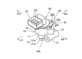
- FIG. 1 It is a perspective view which shows the attachment structure of the rotation angle sensor which concerns on one embodiment of this invention. It is a disassembled perspective view of a rotation angle sensor and a holding body. It is a rear view of a rotation angle sensor It is a left side view of a rotation angle sensor. It is a bottom view of a rotation angle sensor, and is V arrow directional view of FIG. It is a left view of a holding body. It is a top view of a holding body. It is a top view of an interposed member. It is a perspective view of the rotation angle sensor which shows the fitting process which fits an insertion member rotatably in the sensor cylindrical part of a rotation angle sensor, an insertion member, and a holding body.
- FIG. 1 It is a perspective view of a rotation angle sensor, an interposed member, and a holding body which shows the insertion process which inserts the sensor cylindrical part of a rotation angle sensor in the cylindrical holding
- a perspective view of a rotation angle sensor, an insertion member and a holder showing a rotation step of turning the insertion member fitted in the sensor cylindrical portion to make the extension part of the insertion member face a predetermined fastening site is there.
- the mounting structure of the rotation angle sensor according to the present embodiment is, for example, a mounting structure of a rotation angle sensor that detects a rotation angle of a rotating body that is a spur gear provided on a rotation shaft of an internal combustion engine mounted on a vehicle.
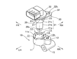
- FIG. 1 is a perspective view showing a state in which a rotation angle sensor 20 is attached to a holder 10 close to a rotating body 1 as a detected rotating body in the present embodiment.
- the rotation angle sensor 20 is attached to the holding body 10 which is a part of a crankcase that rotatably supports the rotation shaft of the rotating body 1 which is a gear.
- the rotation angle sensor 20 includes a sensing unit 21a in which a rotation detection element 20s is present in order to detect the rotation angle of the rotating body 1, and the sensing unit 21a is positioned close to the outer peripheral surface of the rotating body 1 Since the rotation detection element 20s has detection directivity, the rotation detection element 20s is attached to the holder 10 at a predetermined relative angle with respect to the rotating body 1.
- a plurality of convex portions (teeth) 2 are formed at equal intervals in the circumferential direction on the outer peripheral surface of the rotating body 1.
- the rotation angle sensor 20 is located right above the rotating body 1, and the sensing portion 21 a of the tip (lower end) protrusion of the sensor cylindrical portion 21 of the rotation angle sensor 20 is at the uppermost portion of the outer peripheral surface of the rotating body 1. It is close. Then, the detection directivity direction of the rotation detection element 20 s so that the rotation detection element 20 s can detect the movement of the projection 2 in the direction of the velocity vector A at the top of the convex portion 2 that rotates with the rotation of the rotating body 1. It is combined.
- the direction of the velocity vector A is forward FR where the vehicle advances, and the opposite direction is backward RR, forward FR, the left is left LH, and the right is right RH.
- the rotation center axis C of the rotating body 1 is directed horizontally and horizontally, and in a horizontal plane including the rotation center axis C, the direction orthogonal to the rotation center axis C is the front and rear horizontal direction.
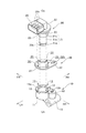
- FIG. 2 is an exploded perspective view of the rotation angle sensor 20 and the holder 10.
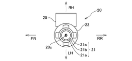
- 3 is a rear view of the rotation angle sensor 20
- FIG. 4 is a left side view of the rotation angle sensor 20
- FIG. 5 is a bottom view taken along the arrow V of FIG. It is assumed that it is attached.
- the rotation angle sensor 20 is attached to the holder 10 in a posture in which the cylinder center axis Cs of the sensor cylindrical portion 21 is directed in the vertical direction.
- the rotation angle sensor 20 has the small diameter sensing portion 21a projecting at the tip (lower end) of the sensor cylindrical portion 21 corresponding to the sensor main body, and a connector 25 as an external harness is integrally formed at the base end Provided in
- the connector 25 is bent from the proximal end of the sensor cylindrical portion 21 and is formed so as to protrude leftward as a rectangular cylinder.
- a connection terminal 25t is provided in the rectangular cylinder of the connector 25 so as to project, and the other connector (not shown) having a connection end of an external harness is detachably connected to the connection terminal 25t.
- the sensing portion 21a is reduced in diameter and protrudes on the tip end side of the central cylindrical portion 21b, and the proximal end cylindrical portion 21c expanded in diameter on the proximal end side of the central cylindrical portion 21b is It is formed.
- the flange portion 22 extending in an annular shape is formed on the base end side of the base end side cylindrical portion 21c in the base end side cylindrical portion 21c, and the connector 25 is integrated with the base end on the flange portion 22. It is provided.
- the convex portions 23 protruding in the radial direction are formed at equal intervals in the circumferential direction at circumferential portions separated from the flange portion 22 by a predetermined distance on the tip end side.
- the convex portions 23 having the same shape are positioned at four places on the front and rear sides and the left and right sides of the proximal end cylindrical portion 21c.
- the projecting end faces of the convex portions 23 respectively projecting from the base end side cylindrical portion 21c in the front and rear and right and left directions are in contact with a circumscribed circle having a diameter slightly smaller than the outer diameter of the flange portion 22.
- the detection directivity direction of the rotation detection element 20s is matched in the front-rear direction which is the movement direction (direction of the velocity vector A) of the uppermost convex portion 2 of the rotary body 1.
- FIG. 6 is a left side view of the holding body 10 which is a part of the crankcase
- FIG. 7 is a top view of the holding body 10.
- the holder 10 has a flat cylindrical cylindrical holding wall 11 for inserting and holding the sensor cylindrical portion 21 of the rotation angle sensor 20, and in the radial direction from the cylindrical holding wall 11.
- the fastening boss 12 is extended.
- the cylinder center axis Ch of the cylindrical holding wall 11 is directed in the vertical direction, and when the rotation angle sensor 20 is attached, it is coaxial with the cylinder center axis Cs of the sensor cylindrical portion 21.
- the inner diameter of the cylindrical holding wall 11 is substantially equal to the outer diameter of the proximal end cylindrical portion 21c of the rotation angle sensor 20, and the outer diameter of the cylindrical holding wall 11 is from the proximal end cylindrical portion 21c of the rotation angle sensor 20
- Each circle is substantially equal to the circumscribed circle of the protruding portion 23.
- a sensor cylinder having a positional relationship in which a recess 13 recessed in a direction (downward) in which the sensor cylindrical portion 21 is inserted from above is detected at the opening end 11e of the cylindrical holding wall 11 to detect the rotation angle of the detected rotating body 1 It is formed in the shape which can be fitted in each front and rear, right and left which each four convex parts 23 of the part 21 can be fitted (refer FIG. 2).
- the sensor cylindrical portion 21 of the rotation angle sensor 20 is inserted from above into the cylindrical holding wall 11 of the holding body 10 at a predetermined relative angle that can detect the rotational angle of the detected rotating body 1
- the base end side cylindrical portion 21c of the sensor cylindrical portion 21 is fitted inside, and the front and rear convex portions 23 of the sensor cylindrical portion 21 are fitted from above into the front and rear left and right recessed portions 13 of the opening upper end of the cylindrical holding wall 11
- the rotation angle sensor 20 is supported by the cylindrical holding wall 11 of the holding body 10.
- the fastening boss 12 extending from the cylindrical holding wall 11 of the holding body 10 tapers obliquely in a top view in a diagonally rearward direction slightly deflected to the right from the rear RR from the cylindrical holding wall 11.
- the fastening boss portion 12 is provided in the direction shifted to the right from the recess 13 on the rear side of the cylindrical holding wall 11.
- a cylindrical portion 15 for component support oriented in the left-right direction is formed at the lower portion of the fastening boss portion 12.
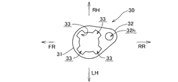
- FIG. 8 is a top view of the interposing member 30 at a position attached to the holder 10.
- the interposing member 30 has an annular portion 31 rotatably fitted between the flange portion 22 and the convex portion 23 of the sensor cylindrical portion 21, and a radial direction from the annular portion 31.
- the extension portion 32 tapers from the annular portion 31 and a bolt mounting hole 32 h is bored in the extension portion 32.
- the inner diameter of the annular portion 31 of the interposing member 30 is substantially equal to the outer diameter of the proximal end cylindrical portion 21 c of the sensor cylindrical portion 21 of the rotation angle sensor 20, and the inner peripheral edge portion of the annular portion 31 A through groove 33 is formed in which the front, rear, left, and right convex portions 23 of the portion 21c penetrate in the axial direction of the cylinder central axis Cs of the sensor cylindrical portion.
- FIG. 8 which is a top view of the interposing member 30 at a position attached to the holder 10, the extension 32 extending radially from the annular portion 31 is slightly more than the rear RR from the annular portion 31.
- the bolt attachment hole 32h of the extension portion 32 tapers out in a diagonally top view from the cylindrical holding wall 11 of the holding body 10 and is deflected slightly to the right from the rear RR. It faces the bolt hole 12 h of the fastening boss 12.
- the process of attaching the rotational angle sensor 20 to the holding body 10 with the interposition member 30 interposed therebetween will be described with reference to FIGS. 2 and 9 to 11.
- the notch 33 of the annular portion 31 of the interposing member 30 is made to face the convex portion 23 of the sensor cylindrical portion 21 (state shown in FIG. 2).
- the annular portion 31 of the interposing member 30 is inserted from the side, and the notch 33 of the interposing member 30 passes the convex portion 23 of the base end side cylindrical portion 21c of the sensor cylindrical portion 21 and the interposing member 30 is flanged 22 And the projection 23 (insertion step).
- FIG. 1 A state in which the interposing member 30 is fitted between the flange portion 22 of the proximal end cylindrical portion 21c and the convex portion 23 is shown in FIG.
- the interposing member 30 is rotatably attached between the flange portion 22 and the projection 23 of the proximal end cylindrical portion 21c of the sensor cylindrical portion 21 of the rotation angle sensor 20. be able to.
- the front and rear convex portions 23 of the sensor cylindrical portion 21 of the rotation angle sensor 20 are opposed to the front and rear concave portions 13 of the cylindrical holding wall 11 of the holder 10 (see FIG. 9).
- the cylindrical portion 21 is inserted, and the rotation angle sensor 20 is held on the cylindrical holding wall 11 of the holding body 10 in a positional relationship that can detect the rotation angle of the detected rotary body 1 (insertion step).
- a state in which the sensor cylindrical portion 21 is inserted into the cylindrical holding wall 11 is shown in FIG.
- the interposed member 30 in a state of being rotatably fitted between the flange portion 22 and the convex portion 23 of the sensor cylindrical portion 21 is rotated as shown by an arrow B in FIG.
- the extending portion 32 of the interposing member 30 is made to face the fastening boss portion 12 of the holder 10, and the bolt mounting hole 32h of the extending portion 32 is aligned with the bolt hole 12h of the fastening boss portion 12 (rotation step).
- FIG. 1 The state which rotated the interposition member 30 is shown in FIG. In this state where the interposing member 30 is rotated, the notch 33 of the interposing member 30 facing the convex portion 23 of the sensor cylindrical portion 21 is not offset from the convex portion 23 and does not oppose.
- the bolt 40 which is a fastening member is passed through the bolt mounting hole 32h of the extending portion 32 of the interposing member 30 which is aligned with the bolt hole 12h of the fastening boss 12
- the extended portion 32 of the interposing member 30 is fastened to the fastening boss 12 of the holder 10 by screwing into the bolt holes 12 h of 12 (fastening (fixing) step).
- a state in which the interposing member 30 is fastened to the holding body 10 is shown in FIG.
- the interposing member 30 By inserting the interposing member 30 to the holding body 10, the interposing member in which the convex portion 23 of the sensor cylindrical portion 21 which does not face the through groove 33 of the interposing member 30 in the rotation step is fastened to the holding body 10
- the rotation angle sensor 20 does not fall out of the cylindrical holding wall 11 of the holding body 10 under the restriction of 30.
- the rotation angle sensor 20 When the rotation angle sensor 20 is attached to the holder 10 through the above steps, as shown in FIG. 1, in the rotation angle sensor 20, the sensing portion 21 a at the tip of the sensor cylindrical portion 21 is the top of the rotating body 1. And the predetermined angle at which the rotation angle of the rotating body 1 can be detected by aligning the detection pointing direction of the rotation detection element 20s so that the rotation detection element 20s in the sensing unit 21a can detect the movement of the convex portion 2 The rotation angle sensor 20 is held by the cylindrical holding wall 11 of the holder 10.
- the opening end 11e of the cylindrical holding wall 11 has a recess 13 in which the projection 23 is fitted, and the recess 13 is detected by the rotation angle sensor 20 when the projection 23 at the opening end 11e is fitted.
- the rotation angle sensor 20 is held by the holding body 10 in a predetermined positional relationship where the rotation angle of the rotary body 1 can be detected.
- the rotation angle sensor 20 Since the movement of the rotation angle sensor 20 is restricted by the interposed member 30 fastened to the predetermined fastening portion 12 of the second embodiment, the convex portion of the sensor cylindrical portion 21 of the rotation angle sensor 20 in the recess 13 of the cylindrical holding wall 11 of the holder 10 The sensor cylindrical portion 21 is inserted into the cylindrical holding wall 11 with the 23 facing each other, and the interposing member 30 between the flange portion 22 and the convex portion 23 of the sensor cylindrical portion 21 is rotated to extend the extending portion 32.
- the rotation angle sensor 20 By fastening to the predetermined fastening portion 12 of the holder 10, the rotation angle sensor 20 is fixed and attached to the holder 10 in a predetermined positional relationship by a simple mounting operation. be able to.
- the interposed member 30 interposed between the flange portion 22 and the convex portion 23 of the sensor cylindrical portion 21 of the rotation angle sensor 20 is fastened to the holding body 10, the movement of the rotation angle sensor 20 by the interposed member 30
- the rotation angle sensor 20 does not fall off from the cylindrical holding wall 11 of the holder 10, and there is no need to perform complicated work such as accurate welding, and the mounting work can be simplified.
- the convex portion 23 of the sensor cylindrical portion 21 is fitted to the concave portion 13 of the cylindrical holding wall 11 to hold and position the rotation angle sensor 20 on the holding body 10 in a predetermined positional relationship (relative angle), and a flange portion
- the function of holding the interposing member 30 rotatably between 22 and 22 to prevent the rotational angle sensor 20 from being removed is also used, and the mounting structure is simplified.
- a notch 33 is formed in the inner peripheral edge of the annular portion 31 of the interposing member 30 so that the convex portion 23 penetrates in the axial direction of the cylindrical central axis Cs of the sensor cylindrical portion 21.
- the notch 33 of the annular portion 31 of the interposing member 30 is opposed to the portion 23 and the annular portion 31 of the interposing member 30 is fitted into the sensor cylindrical portion 21 from the tip end, the notch 33 of the interposing member 30 is convex Since the interposing member 30 is fitted between the flange portion 22 and the convex portion 23 after passing through the portion 23, it is easily interposed between the flange portion 22 of the sensor cylindrical portion 21 of the rotation angle sensor 20 and the convex portion 23.
- the mounting member 30 can be rotatably mounted.
- the notch 33 of the annular portion 31 of the interposing member 30 is a convex of the sensor cylindrical portion 21.
- the interposing member 30 is rotated to a position not facing the portion 23, the convex portion 23 of the sensor cylindrical portion 21 abuts on the annular portion 31 of the interposing member 30, and the rotation angle sensor 20 holds the cylinder of the holder 10 It does not fall off the wall 11.
- a plurality of convex portions 23 are formed at equal intervals in the circumferential direction, and a plurality of concave portions 13 are formed in the cylindrical holding wall 11 corresponding to the respective convex portions 23.
- the plurality of convex portions 23 of the sensor cylindrical portion 21 is fitted in the concave portions 13 formed at equal intervals in the circumferential direction at the opening end 11 e of the cylindrical holding wall 11
- the sensor 20 is held stably with good balance.
- the relative rotational position of the interposing member 30 with respect to the sensor cylindrical portion 21 in which the plurality of notches 33 of the interposing member 30 are opposed to the plurality of equally spaced convex portions 23 of the sensor cylindrical portion 21 is plurally possible. Since the interposition member 30 is easily fitted into the sensor cylindrical portion 21 of the rotation angle sensor 20, the working time can be shortened.
- the interposing member 30 is formed in a plate shape, the gap between the flange portion 22 and the convex portion 23 of the sensor cylindrical portion 21 of the rotation angle sensor 20 can be narrowed, so that the sensor cylindrical portion 21 is short and the rotation angle sensor 20 is miniaturized. And a compact mounting structure.
- the connector 25 detachably connected to the harness is provided at the base end of the sensor cylindrical portion 21, the number of parts can be reduced by integrally forming the rotation angle sensor 20 and the connector 25. Does not affect the installation work.
- the convex portion 23 of the sensor cylindrical portion 21 is opposed to the concave portion 13 of the cylindrical holding wall 11, and the sensor cylindrical portion 21 is inserted into the cylindrical holding wall 11 so that the rotational angle of the rotating body 1 can be detected.
- a fitting process in which the angle sensor 20 is held by the cylindrical holding wall 11 of the holder 10, and the interposed member 30 rotatably fitted between the flange portion 22 and the convex portion 23 of the sensor cylindrical portion 21 are rotated.
- the rotation angle sensor 20 is held by the cylindrical holding wall 11 of the holding body 10 in a positional relationship in which the rotation angle of the detected rotating body 1 can be detected by a simple attachment operation of sequentially performing a fastening (fixing) process.
- the interposition member 30 interposed between the flange portion 22 of the sensor cylindrical portion 21 and the convex portion 23 is fastened to the holding body 10, the convex portion 23 of the sensor cylindrical portion 21 of the rotation angle sensor 20 is interposed There is no need for the member 30 to be restricted and falling off from the cylindrical holding wall 11 of the holding body 10, and it is not necessary to perform complicated work such as accurate welding, and the mounting work can be simplified.
- the notch 33 formed in the annular portion 31 of the interposing member 30 is made to face the convex portion 23 of the sensor cylindrical portion 21, and the annular portion 31 of the interposing member 30 is fitted into the sensor cylindrical portion 21 from the tip side.
- the through groove 33 of the mounting member 30 passes through the convex portion 23, and the interposing member 30 is inserted between the flange portion 22 and the convex portion 23.
- the interposing member 30 can be rotatably attached between the flange portion 22 and the convex portion 23.
- the notch 33 of the annular portion 31 of the interposing member 30 is a convex of the sensor cylindrical portion 21.
- the interposing member 30 is rotated to a position not facing the portion 23, the convex portion 23 of the sensor cylindrical portion 21 abuts on the annular portion 31 of the interposing member 30, and the interposing member 30 fastened to the holding body 10
- the rotation angle sensor 20 does not fall off the cylindrical holding wall 11 of the holding body 10.
- the mode of the present invention is not limited to the above-mentioned embodiment, It is various within the range of the gist of the present invention Including those implemented in the following manner.
- the rotation angle sensor according to the present invention is not limited to one that detects the rotation angle of a rotating body provided on the rotation shaft of an internal combustion engine mounted on a vehicle, but detects rotation angles of various rotating bodies.
- a rotation angle sensor detects the rotation angle of a rotary body, it can also detect the rotation speed of a rotary body by detecting the rotation angle of a rotary body, and is also a rotation speed detection sensor.
Landscapes
- Physics & Mathematics (AREA)
- General Physics & Mathematics (AREA)
- Transmission And Conversion Of Sensor Element Output (AREA)
- Length Measuring Devices With Unspecified Measuring Means (AREA)
Abstract
Selon la présente invention, afin de fixer un capteur d'angle de rotation (20) à un corps de retenue de capteur (10) : un élément intercalé (30) est monté rotatif sur une partie cylindre de capteur de fixation (21) du capteur d'angle de rotation (20) à une position prescrite dans la direction axiale d'un axe central de cylindre (Cs); et la partie cylindre de capteur (21) est ajustée dans une paroi de retenue cylindrique (11) du corps de retenue (10) à une position et une orientation prescrites permettant la détection par le capteur d'angle de rotation (20) de l'angle de rotation d'un corps rotatif à détecter (1), ce qui permet de limiter la rotation du capteur d'angle de rotation (20). Étant donné que l'élément intercalé (30) est fixé au corps de retenue (10), un mouvement axial du capteur d'angle de rotation (20) est limité. Ainsi, le capteur d'angle de rotation peut être fixé au corps de retenue à une position et une orientation prescrites par une opération de fixation simple.
Priority Applications (2)
| Application Number | Priority Date | Filing Date | Title |
|---|---|---|---|
| JP2019549836A JP6864755B2 (ja) | 2017-10-31 | 2018-06-13 | 回転角センサの取付構造および取付方法 |
| DE112018005074.2T DE112018005074B4 (de) | 2017-10-31 | 2018-06-13 | Halterungsstruktur und Montageverfahren für Drehwinkelsensor |
Applications Claiming Priority (2)
| Application Number | Priority Date | Filing Date | Title |
|---|---|---|---|
| JP2017-210488 | 2017-10-31 | ||
| JP2017210488 | 2017-10-31 |
Publications (1)
| Publication Number | Publication Date |
|---|---|
| WO2019087451A1 true WO2019087451A1 (fr) | 2019-05-09 |
Family
ID=66332556
Family Applications (1)
| Application Number | Title | Priority Date | Filing Date |
|---|---|---|---|
| PCT/JP2018/022580 Ceased WO2019087451A1 (fr) | 2017-10-31 | 2018-06-13 | Structure de fixation et procédé de fixation de capteur d'angle de rotation |
Country Status (3)
| Country | Link |
|---|---|
| JP (1) | JP6864755B2 (fr) |
| DE (1) | DE112018005074B4 (fr) |
| WO (1) | WO2019087451A1 (fr) |
Citations (5)
| Publication number | Priority date | Publication date | Assignee | Title |
|---|---|---|---|---|
| JPH0792180A (ja) * | 1993-09-24 | 1995-04-07 | Suzuki Motor Corp | 自動車の車輪回転速度センサー |
| JP2001221656A (ja) * | 2000-02-04 | 2001-08-17 | Asmo Co Ltd | モータアクチュエータ |
| JP2003214902A (ja) * | 2002-01-25 | 2003-07-30 | Yazaki Corp | 回転検出センサ |
| JP2003214903A (ja) * | 2002-01-25 | 2003-07-30 | Yazaki Corp | 回転検出センサ |
| US20060274485A1 (en) * | 2005-06-03 | 2006-12-07 | Arquimedes Godoy | Electrical device enclosure |
Family Cites Families (2)
| Publication number | Priority date | Publication date | Assignee | Title |
|---|---|---|---|---|
| JP2000221206A (ja) | 1999-01-29 | 2000-08-11 | Yazaki Corp | 回転検出センサ及び該回転検出センサの製造方法 |
| DE102008054000B4 (de) | 2008-10-30 | 2013-11-07 | Knorr-Bremse Systeme für Nutzfahrzeuge GmbH | Vorrichtung zur Selbstjustage und Verfahren zur Anordnung eines Impulsdrehzahlgebers in Bezug auf einen Rotor |
-
2018
- 2018-06-13 JP JP2019549836A patent/JP6864755B2/ja active Active
- 2018-06-13 DE DE112018005074.2T patent/DE112018005074B4/de active Active
- 2018-06-13 WO PCT/JP2018/022580 patent/WO2019087451A1/fr not_active Ceased
Patent Citations (5)
| Publication number | Priority date | Publication date | Assignee | Title |
|---|---|---|---|---|
| JPH0792180A (ja) * | 1993-09-24 | 1995-04-07 | Suzuki Motor Corp | 自動車の車輪回転速度センサー |
| JP2001221656A (ja) * | 2000-02-04 | 2001-08-17 | Asmo Co Ltd | モータアクチュエータ |
| JP2003214902A (ja) * | 2002-01-25 | 2003-07-30 | Yazaki Corp | 回転検出センサ |
| JP2003214903A (ja) * | 2002-01-25 | 2003-07-30 | Yazaki Corp | 回転検出センサ |
| US20060274485A1 (en) * | 2005-06-03 | 2006-12-07 | Arquimedes Godoy | Electrical device enclosure |
Also Published As
| Publication number | Publication date |
|---|---|
| DE112018005074T5 (de) | 2020-06-25 |
| DE112018005074B4 (de) | 2024-02-01 |
| JP6864755B2 (ja) | 2021-04-28 |
| JPWO2019087451A1 (ja) | 2020-10-22 |
Similar Documents
| Publication | Publication Date | Title |
|---|---|---|
| JP5758250B2 (ja) | ドアミラー | |
| US11152835B2 (en) | Electric actuator with bus bar holder | |
| JP5775263B2 (ja) | 車両用ミラー装置 | |
| JP5620231B2 (ja) | 車両用ミラー装置 | |
| JP2008109834A (ja) | ブラシレスモータ | |
| TWI379037B (en) | Fuel pump mounting structure | |
| US9539977B2 (en) | Airbag apparatus | |
| JP5867865B2 (ja) | シリンダの取付構造 | |
| US20090183558A1 (en) | Cam/crank sensor that allows for multiple orientations of a plastic over-molded bracket relative to a molded sensor terminal assembly | |
| JP6864755B2 (ja) | 回転角センサの取付構造および取付方法 | |
| JP2009091958A (ja) | 燃料ポンプの取付構造 | |
| JP6609830B2 (ja) | 車両の外界センサユニット | |
| JP5758252B2 (ja) | ドアミラー製造方法 | |
| CN210769519U (zh) | 风机 | |
| KR20100012780A (ko) | 회전 센서 장치 | |
| JP4105291B2 (ja) | ステアリング機構およびその組付け方法 | |
| JP5887899B2 (ja) | センサ装置 | |
| CN111810442B (zh) | 风机 | |
| JP6501346B2 (ja) | サイドスタンドの位置検出装置 | |
| JP2014222694A (ja) | 通気部材、通気部材取付冶具および電子装置 | |
| JP6709858B2 (ja) | スタンドの位置検出装置 | |
| JPS6011458Y2 (ja) | ロ−タリ−エンコ−ダ− | |
| JP4045821B2 (ja) | 転がり軸受装置におけるシール部材の取付け方法 | |
| JP2009127479A (ja) | ファンのアンバランス修正構造 | |
| US11048287B1 (en) | Mounting assembly for a control pedal of a vehicle |
Legal Events
| Date | Code | Title | Description |
|---|---|---|---|
| 121 | Ep: the epo has been informed by wipo that ep was designated in this application |
Ref document number: 18874596 Country of ref document: EP Kind code of ref document: A1 |
|
| ENP | Entry into the national phase |
Ref document number: 2019549836 Country of ref document: JP Kind code of ref document: A |
|
| 122 | Ep: pct application non-entry in european phase |
Ref document number: 18874596 Country of ref document: EP Kind code of ref document: A1 |