WO2019087559A1 - スラリー製造装置、およびスラリー製造装置の運転方法 - Google Patents
スラリー製造装置、およびスラリー製造装置の運転方法 Download PDFInfo
- Publication number
- WO2019087559A1 WO2019087559A1 PCT/JP2018/032580 JP2018032580W WO2019087559A1 WO 2019087559 A1 WO2019087559 A1 WO 2019087559A1 JP 2018032580 W JP2018032580 W JP 2018032580W WO 2019087559 A1 WO2019087559 A1 WO 2019087559A1
- Authority
- WO
- WIPO (PCT)
- Prior art keywords
- powder
- slurry
- dry box
- hopper
- supply
- Prior art date
- Legal status (The legal status is an assumption and is not a legal conclusion. Google has not performed a legal analysis and makes no representation as to the accuracy of the status listed.)
- Ceased
Links
Images





Classifications
-
- B—PERFORMING OPERATIONS; TRANSPORTING
- B01—PHYSICAL OR CHEMICAL PROCESSES OR APPARATUS IN GENERAL
- B01F—MIXING, e.g. DISSOLVING, EMULSIFYING OR DISPERSING
- B01F23/00—Mixing according to the phases to be mixed, e.g. dispersing or emulsifying
- B01F23/50—Mixing liquids with solids
- B01F23/59—Mixing systems, i.e. flow charts or diagrams
-
- B—PERFORMING OPERATIONS; TRANSPORTING
- B01—PHYSICAL OR CHEMICAL PROCESSES OR APPARATUS IN GENERAL
- B01F—MIXING, e.g. DISSOLVING, EMULSIFYING OR DISPERSING
- B01F23/00—Mixing according to the phases to be mixed, e.g. dispersing or emulsifying
- B01F23/50—Mixing liquids with solids
-
- B—PERFORMING OPERATIONS; TRANSPORTING
- B01—PHYSICAL OR CHEMICAL PROCESSES OR APPARATUS IN GENERAL
- B01F—MIXING, e.g. DISSOLVING, EMULSIFYING OR DISPERSING
- B01F23/00—Mixing according to the phases to be mixed, e.g. dispersing or emulsifying
- B01F23/50—Mixing liquids with solids
- B01F23/53—Mixing liquids with solids using driven stirrers
-
- B—PERFORMING OPERATIONS; TRANSPORTING
- B01—PHYSICAL OR CHEMICAL PROCESSES OR APPARATUS IN GENERAL
- B01F—MIXING, e.g. DISSOLVING, EMULSIFYING OR DISPERSING
- B01F23/00—Mixing according to the phases to be mixed, e.g. dispersing or emulsifying
- B01F23/50—Mixing liquids with solids
- B01F23/565—Mixing liquids with solids by introducing liquids in solid material, e.g. to obtain slurries
-
- B—PERFORMING OPERATIONS; TRANSPORTING
- B01—PHYSICAL OR CHEMICAL PROCESSES OR APPARATUS IN GENERAL
- B01F—MIXING, e.g. DISSOLVING, EMULSIFYING OR DISPERSING
- B01F23/00—Mixing according to the phases to be mixed, e.g. dispersing or emulsifying
- B01F23/70—Pre-treatment of the materials to be mixed
- B01F23/704—Drying materials, e.g. in order to mix them in solid state
-
- B—PERFORMING OPERATIONS; TRANSPORTING
- B01—PHYSICAL OR CHEMICAL PROCESSES OR APPARATUS IN GENERAL
- B01F—MIXING, e.g. DISSOLVING, EMULSIFYING OR DISPERSING
- B01F25/00—Flow mixers; Mixers for falling materials, e.g. solid particles
- B01F25/50—Circulation mixers, e.g. wherein at least part of the mixture is discharged from and reintroduced into a receptacle
- B01F25/52—Circulation mixers, e.g. wherein at least part of the mixture is discharged from and reintroduced into a receptacle with a rotary stirrer in the recirculation tube
-
- B—PERFORMING OPERATIONS; TRANSPORTING
- B01—PHYSICAL OR CHEMICAL PROCESSES OR APPARATUS IN GENERAL
- B01F—MIXING, e.g. DISSOLVING, EMULSIFYING OR DISPERSING
- B01F25/00—Flow mixers; Mixers for falling materials, e.g. solid particles
- B01F25/50—Circulation mixers, e.g. wherein at least part of the mixture is discharged from and reintroduced into a receptacle
- B01F25/53—Circulation mixers, e.g. wherein at least part of the mixture is discharged from and reintroduced into a receptacle in which the mixture is discharged from and reintroduced into a receptacle through a recirculation tube, into which an additional component is introduced
-
- B—PERFORMING OPERATIONS; TRANSPORTING
- B01—PHYSICAL OR CHEMICAL PROCESSES OR APPARATUS IN GENERAL
- B01F—MIXING, e.g. DISSOLVING, EMULSIFYING OR DISPERSING
- B01F25/00—Flow mixers; Mixers for falling materials, e.g. solid particles
- B01F25/60—Pump mixers, i.e. mixing within a pump
-
- B—PERFORMING OPERATIONS; TRANSPORTING
- B01—PHYSICAL OR CHEMICAL PROCESSES OR APPARATUS IN GENERAL
- B01F—MIXING, e.g. DISSOLVING, EMULSIFYING OR DISPERSING
- B01F25/00—Flow mixers; Mixers for falling materials, e.g. solid particles
- B01F25/60—Pump mixers, i.e. mixing within a pump
- B01F25/64—Pump mixers, i.e. mixing within a pump of the centrifugal-pump type, i.e. turbo-mixers
-
- B—PERFORMING OPERATIONS; TRANSPORTING
- B01—PHYSICAL OR CHEMICAL PROCESSES OR APPARATUS IN GENERAL
- B01F—MIXING, e.g. DISSOLVING, EMULSIFYING OR DISPERSING
- B01F35/00—Accessories for mixers; Auxiliary operations or auxiliary devices; Parts or details of general application
-
- B—PERFORMING OPERATIONS; TRANSPORTING
- B01—PHYSICAL OR CHEMICAL PROCESSES OR APPARATUS IN GENERAL
- B01F—MIXING, e.g. DISSOLVING, EMULSIFYING OR DISPERSING
- B01F35/00—Accessories for mixers; Auxiliary operations or auxiliary devices; Parts or details of general application
- B01F35/71—Feed mechanisms
-
- B—PERFORMING OPERATIONS; TRANSPORTING
- B01—PHYSICAL OR CHEMICAL PROCESSES OR APPARATUS IN GENERAL
- B01F—MIXING, e.g. DISSOLVING, EMULSIFYING OR DISPERSING
- B01F35/00—Accessories for mixers; Auxiliary operations or auxiliary devices; Parts or details of general application
- B01F35/71—Feed mechanisms
- B01F35/711—Feed mechanisms for feeding a mixture of components, i.e. solids in liquid, solids in a gas stream
-
- B—PERFORMING OPERATIONS; TRANSPORTING
- B01—PHYSICAL OR CHEMICAL PROCESSES OR APPARATUS IN GENERAL
- B01F—MIXING, e.g. DISSOLVING, EMULSIFYING OR DISPERSING
- B01F35/00—Accessories for mixers; Auxiliary operations or auxiliary devices; Parts or details of general application
- B01F35/71—Feed mechanisms
- B01F35/717—Feed mechanisms characterised by the means for feeding the components to the mixer
- B01F35/7173—Feed mechanisms characterised by the means for feeding the components to the mixer using gravity, e.g. from a hopper
- B01F35/71731—Feed mechanisms characterised by the means for feeding the components to the mixer using gravity, e.g. from a hopper using a hopper
-
- B—PERFORMING OPERATIONS; TRANSPORTING
- B01—PHYSICAL OR CHEMICAL PROCESSES OR APPARATUS IN GENERAL
- B01F—MIXING, e.g. DISSOLVING, EMULSIFYING OR DISPERSING
- B01F35/00—Accessories for mixers; Auxiliary operations or auxiliary devices; Parts or details of general application
- B01F35/90—Heating or cooling systems
-
- B—PERFORMING OPERATIONS; TRANSPORTING
- B01—PHYSICAL OR CHEMICAL PROCESSES OR APPARATUS IN GENERAL
- B01F—MIXING, e.g. DISSOLVING, EMULSIFYING OR DISPERSING
- B01F35/00—Accessories for mixers; Auxiliary operations or auxiliary devices; Parts or details of general application
- B01F35/90—Heating or cooling systems
- B01F35/93—Heating or cooling systems arranged inside the receptacle
-
- H—ELECTRICITY
- H01—ELECTRIC ELEMENTS
- H01M—PROCESSES OR MEANS, e.g. BATTERIES, FOR THE DIRECT CONVERSION OF CHEMICAL ENERGY INTO ELECTRICAL ENERGY
- H01M10/00—Secondary cells; Manufacture thereof
- H01M10/05—Accumulators with non-aqueous electrolyte
- H01M10/056—Accumulators with non-aqueous electrolyte characterised by the materials used as electrolytes, e.g. mixed inorganic/organic electrolytes
- H01M10/0561—Accumulators with non-aqueous electrolyte characterised by the materials used as electrolytes, e.g. mixed inorganic/organic electrolytes the electrolyte being constituted of inorganic materials only
- H01M10/0562—Solid materials
-
- H—ELECTRICITY
- H01—ELECTRIC ELEMENTS
- H01M—PROCESSES OR MEANS, e.g. BATTERIES, FOR THE DIRECT CONVERSION OF CHEMICAL ENERGY INTO ELECTRICAL ENERGY
- H01M4/00—Electrodes
- H01M4/02—Electrodes composed of, or comprising, active material
- H01M4/13—Electrodes for accumulators with non-aqueous electrolyte, e.g. for lithium-accumulators; Processes of manufacture thereof
- H01M4/139—Processes of manufacture
-
- B—PERFORMING OPERATIONS; TRANSPORTING
- B01—PHYSICAL OR CHEMICAL PROCESSES OR APPARATUS IN GENERAL
- B01F—MIXING, e.g. DISSOLVING, EMULSIFYING OR DISPERSING
- B01F35/00—Accessories for mixers; Auxiliary operations or auxiliary devices; Parts or details of general application
- B01F35/90—Heating or cooling systems
- B01F2035/98—Cooling
-
- B—PERFORMING OPERATIONS; TRANSPORTING
- B01—PHYSICAL OR CHEMICAL PROCESSES OR APPARATUS IN GENERAL
- B01F—MIXING, e.g. DISSOLVING, EMULSIFYING OR DISPERSING
- B01F2101/00—Mixing characterised by the nature of the mixed materials or by the application field
- B01F2101/59—Mixing reaction ingredients for fuel cells
-
- Y—GENERAL TAGGING OF NEW TECHNOLOGICAL DEVELOPMENTS; GENERAL TAGGING OF CROSS-SECTIONAL TECHNOLOGIES SPANNING OVER SEVERAL SECTIONS OF THE IPC; TECHNICAL SUBJECTS COVERED BY FORMER USPC CROSS-REFERENCE ART COLLECTIONS [XRACs] AND DIGESTS
- Y02—TECHNOLOGIES OR APPLICATIONS FOR MITIGATION OR ADAPTATION AGAINST CLIMATE CHANGE
- Y02E—REDUCTION OF GREENHOUSE GAS [GHG] EMISSIONS, RELATED TO ENERGY GENERATION, TRANSMISSION OR DISTRIBUTION
- Y02E60/00—Enabling technologies; Technologies with a potential or indirect contribution to GHG emissions mitigation
- Y02E60/10—Energy storage using batteries
Definitions
- the present invention relates to a slurry production apparatus and an operation method of the slurry production apparatus.
- Patent Document 1 discloses a dispersion system in which powder and liquid supplied to a hopper are sucked and mixed by a centrifugal dispersion and mixing pump.
- Patent No. 5625216 gazette
- Some powders serving as the material of the slurry absorb moisture in the air to deteriorate or harden.
- the apparatus of patent document 1 uses such powder, the following problems will arise.
- the upper inlet of the hopper is open. Then, when the powder is introduced into the hopper or when the powder stored in the hopper is stirred, the powder absorbs the moisture of the surrounding air, and the quality of the slurry is deteriorated.
- Dehumidifying the room in which the apparatus is installed can be considered as a method of preventing moisture absorption of the powder, but it takes a great running cost to dehumidify a large room for a long time.
- the maintainability is significantly reduced.
- This invention is made in view of the above-mentioned subject,
- the objective is to provide the method of the slurry manufacture which suppressed the slurry quality fall, the running cost increase, and the maintainability fall.
- the characteristic configuration of the slurry producing device for achieving the above object is a mixing device for producing a slurry by mixing a liquid and a powder, a powder feeding device for feeding the powder to the mixing device, and for powder A dry box is provided, and an opening of the powder supply device is accommodated in the powder dry box.
- the opening of the powder supply device is housed in the dry box for powder, it is possible to prevent the powder from touching wet air and to suppress the deterioration of the quality of the slurry. it can. And since the dry box for powder only needs to accommodate at least the opening of the powder supply device, large-scale equipment becomes unnecessary, and it is possible to suppress an increase in running cost and a decrease in maintainability.
- the powder feeding device has a hopper whose upper side is open and a feeder for feeding the powder to the hopper, and the opening of the hopper and the feeder And the powder outlet of the powder is accommodated in the powder dry box.
- the hopper opening and the feeder powder outlet are housed in the powder dry box, so that the powder can be prevented from coming in contact with damp air, and the quality of the slurry is degraded. Can be suppressed.
- the powder feeding device has a feeder hopper for feeding powder to the feeder, and the air vent of the feeder hopper is in the powder dry box. It is in the connected point.
- the dried air in the feeder hopper can be used in the powder dry box, further increasing the running cost It can be suppressed.
- FIG. 4 Another characteristic configuration of the slurry production apparatus according to the present invention is that the apparatus has a main body dry box for housing the mixing apparatus therein.
- the main body dry box for containing the mixing device since the main body dry box for containing the mixing device is provided, it is possible to more appropriately avoid the situation where the powder comes in contact with damp air and to suppress the deterioration of the quality of the slurry.
- the required dryness is lower than that of the powder dry box. According to the above-described feature configuration, since the dew point temperature of the main body dry box is higher than the dew point temperature of the powder dry box, it is possible to further suppress an increase in running cost.
- FIG. 6 Another characteristic configuration of the slurry production apparatus according to the present invention is that a cooling device for cooling the mixing device is housed inside the dry box for the main body.
- the mixing device may be provided with a cooling device in order to suppress deterioration of the slurry due to temperature rise.
- a cooling device since the cooling device for cooling the mixing device is housed inside the main body dry box, it is possible to suppress the occurrence of dew condensation on the surface of the cooling device, which is preferable.
- the mixing device is a centrifugal dispersive mixing pump.
- the slurry production apparatus is suitably applicable to production of a positive electrode active material layer slurry, a negative electrode active material slurry, or a solid electrolyte slurry used for production of an all-solid battery.
- the slurry production apparatus according to the present invention is suitably applicable when the powder contains a sulfide solid electrolyte.
- the characterizing feature of the method of operating the slurry production apparatus to achieve the above object is the method of operating the slurry production apparatus,
- the slurry production apparatus includes a mixing device for mixing a liquid and a powder to produce a slurry, a powder feeding device for supplying the powder to the mixing device, a powder dry box, and the mixing device.
- the opening of the powder supply device is accommodated in the powder dry box, While the powder is supplied from the powder supply device to the mixing device, both the powder dry box and the main body dry box are operated, When the supply of the powder from the powder supply device to the mixing device is completed, the operation of the powder dry box is stopped and the operation of the main body dry box is performed.
- the powder may come into contact with damp air Can be avoided and the quality deterioration of the slurry can be suppressed. Then, when the supply of the powder from the powder supply device to the mixing device is completed, the operation of the powder dry box is stopped and the operation of the main body dry box is performed, so that an increase in running cost can be suppressed.
- the supply of the powder is completed, the supply of the powder from the powder supply device to the mixing device is completed and no powder remains in the powder supply device, and Although powder remains, the supply of powder from the powder supply device into the mixing device is stopped, and the powder supply port to the powder supply device from the outside is blocked by a lid, a shutter, etc. Including the case where the powder feeding device is sealed.
- FIG. 5 Diagram showing the outline of the slurry production system Schematic diagram of dispersion system with centrifugal suction pump mechanism Longitudinal sectional view showing the main part of the powder supply device Sectional view in IV-IV direction view of FIG. 3 Longitudinal side view of centrifugal suction pump mechanism Sectional view in the VI-VI direction view of FIG. 5
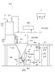
- the slurry production apparatus 200 is configured to include a dispersion system 100, a powder dry box 230, a main body dry box 240, and a control unit C. .
- the dispersion system 100 includes a powder supply device X, a suction pump mechanism Y, a mixing mechanism 60, a recirculation mechanism 70, a cooling device 250, a tank 260, and a pressure relief unit 270. ing.
- the slurry F is produced as follows.
- the powder P supplied from the powder supply device X and the liquid R (or slurry F) supplied from the tank 260 by the pump 261 are mixed by the mixing mechanism 60 and supplied to the suction pump mechanism Y.
- the suction pump mechanism Y the powder P and the liquid R are dispersed and mixed, and are sent to the recirculation mechanism 70.
- the recirculation mechanism unit 70 circulates and supplies the liquid R containing the powder P not completely dissolved (hereinafter, undissolved slurry Fr) to the suction pump mechanism unit Y, and delivers the slurry F to the tank 260.
- the slurry F inside the tank 260 is agitated by the tank agitation motor M4.
- the powder dry box 230 and the main body dry box 240 divide the internal space from the external space by, for example, a synthetic resin panel in order to keep only the atmosphere of a limited necessary place in a predetermined state. is there.
- the powder dry box 230 and the main body dry box 240 may be made of various materials having heat insulation, metal, etc. as long as they can prevent moisture of the powder P in the internal space by using them. May be
- the powder dry box 230 is configured to have an outer box 231 and an inner box 232.
- the intake side of the dehumidifying unit 233 is connected to the outer box 231, and the exhaust side is connected to the inner box 232.
- the operating conditions of the dehumidifying unit 233 are adjusted, and the pressure in the inner box 232 is positive pressure, ie, about 2 to 3 Pa, for example, higher than the pressure outside the powder dry box 230 (hereinafter referred to as “external pressure”). It is held in the state.
- the pressure in the outer box 231 is maintained at a negative pressure, that is, for example, about 1 to 2 Pa, lower than the outside pressure.
- the dew point temperature of the outer box 231 is maintained, for example, at -40 ° C. or less, and the dew point temperature of the inner box 232 is maintained, for example, at -70 ° C. or less.
- the dew point temperature of the inner box 232 is adjusted lower in the outer box 231, and the dew point temperature is further lowered adjusted in the inner box 232 to lower the dew point temperature stepwise. it can.
- adjustment of the low dew point temperature in the inner side box 232 is easy, and a running cost can be reduced.
- the dew point temperature of the outer side box 231 and the inner side box 232 is not limited to said thing, According to the property etc. of the powder P, it can set suitably. Further, as described above, by setting the pressure in the outer box 231 to a negative pressure than the outside pressure, it is possible to suppress the odor contained in the outer box 231 from being diffused to the outside. In addition, since the air pressure in the inner box 232 is higher than the air pressure in the outer box 231, the flow of air toward the inner box 232 is blocked, and the dew point temperature of the inner box 232 is easily adjusted. it can.
- the main body dry box 240 has a single-layer structure.
- the main body dry box 240 is maintained at a dew point temperature of, for example, ⁇ 40 ° C. or less by a dehumidifying unit (not shown).
- the dew point temperature of the outer box 231 is maintained at, for example, -40 ° C. or less
- the dew point temperature of the inner box 232 is maintained at, for example, -70 ° C. or less
- the dew point temperature of the body dry box 240 is maintained at, for example, -40 ° C. or less
- the flow of air is, for example, the following two systems.
- One of the two systems is the flow of air in the powder dry box 230, and from the dehumidifying unit 233 for the powder dry box 230, the inner box 232 (positive pressure than the outside pressure), the outer box Air flows by circulation of a flow of 231 (negative pressure than the outside pressure) and the dehumidifying unit 233.
- Another system of the two systems is the flow of air in the main body dry box 240, and air flows from the dehumidifying unit (not shown) through the flow of the main body dry box 240 and the dehumidifying unit (not shown).
- the dew point temperature of the main body dry box 240 may be any temperature that does not cause condensation in the cooling device 250, and may be, for example, -20 ° C to -30 ° C.
- the air flow can be performed, for example, as follows. From the dehumidifying unit 233 for the powder dry box 230, to the inner box 232 (positive pressure from outside pressure), the main body dry box 240, the outer box 231 (negative pressure from outside pressure), and further to the dehumidifying unit 233 in this order I can flow the air.
- the main body dry box 240 is set to a positive pressure than the outer box 231 and to a negative pressure than the inner box 232.
- the dehumidifying unit 233 can be shared by the powder dry box 230 and the main body dry box 240, and a dehumidifying unit (not shown) for the main body dry box 240 can be used together with the dehumidifying unit 233. It is not necessary to provide separately, which can suppress cost increase.
- the powder supply device X includes a feeder hopper 210, a feeder 220, and a hopper 31.
- the feeder hopper 210 is a hopper for temporarily storing the powder P dry-conveyed from the upstream.
- the feeder hopper 210 has an air vent 211 connected to the powder dry box 230.
- the air vent 211 discharges the dried air inside the feeder hopper 210 to the powder dry box 230 when the internal pressure of the feeder hopper 210 increases with the introduction of the powder P from the upstream.
- the air vent 211 is provided with a check valve so that the feeder hopper 210 is closed so that the powder P is not affected by moisture when pressure is not applied to the feeder hopper 210.
- the feeder 220 discharges the powder P stored in the feeder hopper 210 from the powder discharge port 221 (an example of the opening) while measuring.
- the feeder 220 is, for example, a screw feeder.
- the powder outlet 221 is disposed inside the inner box 232 of the powder dry box 230.
- the powder P discharged from the powder discharge port 221 drops the inside of the inner box 232 of the powder dry box, and is thrown into the hopper 31 from the upper opening 31 a of the hopper 31.
- the hopper 31 is an inverted conical member whose diameter decreases from the top to the bottom, and discharges the powder P received from the upper opening 31 a from the lower opening 31 b and supplies it to the mixing mechanism 60. .
- the upper opening 31 a of the hopper 31 is disposed inside the inner box 232 of the powder dry box 230.
- the powder discharge port 221 of the feeder 220 which is the opening of the powder feeder X
- the upper opening 31a of the hopper 31 form the inner box 232 of the powder dry box 230. It is stored.
- the air vent 211 of the feeder hopper 210 is connected to the outer box 231 of the powder dry box 230.
- the cooling device 250 is a device for cooling the suction pump mechanism Y.
- the cooling device 250 is a cold water jacket through which the supplied cold water flows, and is provided to cover the main casing 1 and the recirculation mechanism 70 of the suction pump mechanism Y.
- the suction pump mechanism Y (example of the mixing device), the mixing mechanism 60, the recirculation mechanism 70, the cooling device 250, and the tank 260 are dry for the main body. It is housed inside the box 240.
- the dew point temperature of the main body dry box 240 is, for example, ⁇ 40 ° C., which is higher than ⁇ 70 ° C. which is an example of the dew point temperature of the powder dry box 230.
- the pressure relief unit 270 evacuates the tank 260 to reduce the pressure in the tank 260.
- the pressure relief unit 270 is a gas flow path, and connects the inside of the tank 260 and the outer box 231 of the powder dry box 230 via a valve.
- a gas flow path which is branched from the valve and exhausts from the tank 260 to the outside is provided, and a filter 271 is disposed in the gas flow path.
- the filter 271 When exhausting from the tank 260 to the outside, the gas in the tank 260 is exhausted through the filter 271. This suppresses offensive odors and scattering of substances.
- the control unit C includes an arithmetic processing unit provided with a CPU, a storage unit, and the like, and controls the overall operation of the slurry production apparatus 200.
- the control unit C controls the operation of the powder dry box 230 and the main body dry box 240.
- the control unit C operates both the powder dry box 230 and the main body dry box 240 while supplying the powder from the powder supply device X to the suction pump mechanism Y (mixing device). Then, when the supply of the powder from the powder supply device X to the suction pump mechanism Y is completed, the operation of the powder dry box 230 is stopped, and the operation of the main body dry box 240 is performed.
- the supply of the powder is completed, the supply of the powder from the powder supply device X to the suction pump mechanism (mixing device) Y is completed, and the powder does not remain in the powder supply device X
- the powder feeding from the powder feeding device X into the suction pump mechanism Y is stopped, and the powder feeding device X from the outside is stopped.
- the case where the powder supply port is closed by a lid, a shutter or the like (not shown) and the powder supply apparatus X is sealed is included. As described above, even if the powder remains in the powder feeding device X, by sealing the powder feeding device X, it is possible to suppress that the powder absorbs moisture.
- the feeder hopper 210 and the feeder 220 of the powder feeding device X and the powder dry box 230 are placed on the rack 280, and the suction pump mechanism Y It is disposed above the (mixing device).
- the upper opening 31 a of the hopper 31 is disposed above the rack 280.
- the lower opening (31 b) of the hopper 31 is disposed below the gantry 280.
- the slurry production apparatus 200 it is possible to produce the slurry F using various kinds of powders P and liquids R.
- the slurry production apparatus 200 can be suitably used for producing a positive electrode, a negative electrode, or a slurry for producing a solid electrolyte of an all solid battery, that is, a positive electrode active material layer slurry, a negative electrode active material slurry, or a solid electrolyte slurry.
- the positive electrode active material slurry is manufactured by dispersing a positive electrode active material, a conductive additive, a binder and the like in a solvent.
- the negative electrode active material slurry is manufactured by dispersing a negative electrode active material, a conductive additive, a binder and the like in a solvent.
- the solid electrolyte slurry is manufactured by dispersing a solid electrolyte, a conductive additive, a binder and the like in a solvent.
- the positive electrode active material slurry may contain a solid electrolyte.
- the negative electrode active material slurry may contain a solid electrolyte.
- An olivine type positive electrode active material is illustrated as a positive electrode active material.
- An olivine type positive electrode active material is a substance which has an olivine type structure, and if it is a positive electrode active material which can be used for a lithium ion battery, it will not be specifically limited.
- the active material represented by the chemical formula of ⁇ 7 can be raised.
- LiFePO 4 which is an olivine-type positive electrode active material having high stability of the material and large theoretical capacity is preferable.
- the negative electrode active material is not particularly limited as long as lithium ions and the like can be absorbed and released.
- Specific examples of the negative electrode active material include metals such as Li, Sn, Si, or In, alloys of Li and Ti, Mg or Al, or carbon materials such as hard carbon, soft carbon or graphite, or A combination of these can be mentioned.
- lithium titanate (LTO, Li 4 Ti 5 O 12 ) and lithium-containing alloys are preferable from the viewpoint of cycle characteristics and discharge characteristics.
- a sulfide solid electrolyte used as a solid electrolyte of an all solid battery can be used.
- Li 2 S-SiS 2 , LiX-Li 2 S-SiS 2 , LiX-Li 2 S-P 2 S 5 , LiX-Li 2 S-P 2 S 5 , LiX-Li 2 S-Li 2 O- P 2 S 5 , Li 2 S-P 2 S 5 , Li 3 PS 4 -LiI-LiBr and the like can be mentioned.
- “X” represents I and / or Br.
- a conductive support agent in addition to carbon materials such as vapor grown carbon fiber (VGCF), acetylene black, ketjen black, carbon nanotube (CNT) or carbon nanofiber (CNF), nickel aluminum stainless steel etc. Metals or combinations thereof are exemplified.
- VGCF vapor grown carbon fiber
- CNT carbon nanotube
- CNF carbon nanofiber
- polymer resin such as polyvinylidene fluoride (PVDF), polytetrafluoroethylene (PTFE), polyimide (PI), polyamide (PA), polyamide imide (PAI), butadiene rubber (BR), styrene butadiene rubber ( SBR), nitrile-butadiene rubber (NBR), styrene-ethylene-butylene-styrene block copolymer (SEBS), carboxymethylcellulose (CMC), etc., or a combination thereof is exemplified.
- PVDF polyvinylidene fluoride
- PTFE polytetrafluoroethylene
- PI polyimide
- PA polyamide
- PAI polyamide imide
- BR butadiene rubber
- SBR styrene butadiene rubber
- NBR nitrile-butadiene rubber
- SEBS styrene-ethylene-butylene-styrene block copolymer
- solvent examples include butyl butyrate and dehydrated heptane.
- the powder feeding device X includes a hopper 31 for discharging the powder P received from the upper opening 31a from the lower opening 31b, and a stirring mechanism 32 for stirring the powder P in the hopper 31.
- the upper opening 31a of the hopper 31 is open to the atmosphere, the negative pressure suction force acting on the lower opening 31b by the suction of the suction pump mechanism Y connected to the downstream side of the lower opening 31b causes the lower opening
- the apparatus further comprises: a volumetric fixed amount supply unit 40 configured to quantitatively supply the powder P discharged from the portion 31 b to the suction pump mechanism Y.
- the hopper 31 is formed in an inverted conical shape whose diameter decreases as it goes from the top to the bottom, and the central axis A1 of the hopper 31 is disposed in a posture along the vertical direction.
- the cross sectional shape of each of the upper opening 31a and the lower opening 31b of the hopper 31 is a circular shape centering on the central axis A1 in the vertical direction of FIG. Is generally about 60 degrees with respect to the horizontal plane.
- the inclination angle can be changed according to the properties of the powder. For example, when the powder is carbon black, the inclination angle can be, for example, approximately 45 degrees.
- the stirring mechanism 32 is disposed in the hopper 31 and a stirring blade 32A for stirring the powder P in the hopper 31, and a blade drive motor M1 for rotating the stirring blade 32A around a central axis A1 of the hopper 31;
- a mounting member 32B for supporting the blade drive motor M1 above the upper opening 31a of the hopper 31 and a transmission member 32C for transmitting the rotational driving force of the blade drive motor M1 to the stirring blade 32A.
- the stirring blade 32A is configured by bending a rod-like member into a substantially V shape, and one end of the stirring blade 32A is along the inner wall surface of the hopper 31, and the other end is the central axis A1 of the hopper 31. It is coaxially rotatably supported. Further, the stirring blade 32A is formed to have a triangular cross-sectional shape, and the surface forming one side of the triangle is disposed substantially parallel to the inner wall surface of the hopper 31. Thus, the stirring blade 32A is disposed rotatably around the central axis A1 along the inner wall surface of the hopper 31.
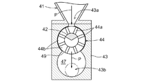
- the volumetric fixed amount supply unit 40 is a mechanism for quantitatively supplying the powder P supplied from the lower opening 31 b of the hopper 31 to the suction pump mechanism Y on the downstream side by a predetermined amount. It is. Specifically, the introduction portion 41 connected to the lower opening 31 b of the hopper 31, the casing 43 provided with the supply port 43 a and the discharge port 43 b, and the measuring rotating body 44 rotatably disposed in the casing 43 And a measuring rotary body drive motor M2 that rotationally drives the measuring rotary body 44.
- the introduction portion 41 is formed in a tubular shape that communicates the lower opening 31 b of the hopper 31 and the supply port 43 a formed in the upper portion of the casing 43, and a slit having the same shape as the supply port 43 a of the casing 43 at the lowermost end. Shaped openings are formed.
- the introduction portion 41 is formed in a tapered shape which becomes thinner toward the supply port 43 a of the casing 43.
- the shape of the slit-like opening can be appropriately set according to the size of the hopper 31, the supply amount of the powder P, the characteristics of the powder P, etc. For example, the length direction of the slit-like opening The dimension is set to about 20 to 100 mm, and the dimension in the width direction is set to about 1 to 5 mm.
- the casing 43 is formed in a substantially rectangular parallelepiped shape, and is connected to the hopper 31 via the introduction portion 41 in a posture inclined at 45 degrees with respect to the horizontal direction (left and right direction in FIG. 2).
- a slit-like supply port 43 a corresponding to the slit-like opening of the introduction portion 41 is provided on the upper surface of the casing 43, and the powder P from the lower opening 31 b of the hopper 31 is provided.
- the powder P supplied by the fixed amount by the measuring rotating body 44 is drawn through the expansion chamber 47 to the suction pump on the downstream side.
- a discharge port 43 b for discharging to the mechanism section Y is provided, and a powder discharge pipe 45 is connected to the discharge port 43 b.
- the expansion chamber 47 is provided at a position in the casing 43 to which the powder P supplied from the supply port 43a to the powder storage chamber 44b of the measuring rotary body 44 is quantitatively supplied, and negative pressure suction acting from the discharge port 43b The force is maintained at a lower pressure than the supply port 43a (eg, about -0.06 MPa). That is, by connecting the discharge port 43b to the primary side of the suction pump mechanism Y, a negative pressure suction force is applied to the expansion chamber 47 so as to be maintained at a lower pressure than the supply port 43a. With the rotation of the measuring rotary body 44, the state of each powder storage chamber 44b is configured to change to a negative pressure state (for example, about -0.06 MPa) and a higher pressure state than the negative pressure state. .
- a plurality of (for example, eight) plate-like partition walls 44a are formed radially on the disc member 49 disposed on the drive shaft 48 of the measuring and rotating body drive motor M2, excluding the central portion of the disc member 49. It is attached to a space
- the powder storage chamber 44 b is configured to open at the outer peripheral surface and the central portion of the measuring rotating body 44.
- An opening closing member 42 is disposed in a fixed manner at a central portion of the measuring rotating body 44 so as to be unevenly distributed in the circumferential direction, and the opening on the central portion side of each powder containing chamber 44b is closed or opened according to its rotational phase. It is configured to be possible.
- the amount of powder P supplied can be adjusted by changing the number of rotations of the measuring rotator 44 by the measuring rotator drive motor M2 that rotationally drives the measuring rotator 44.
- Each powder storage chamber 44b is opened to the expansion chamber 47 with the rotation of the measuring rotary body 44, the first sealed state not communicating with the expansion chamber 47 and the supply port 43a, the supply port 43a is opened.
- the state is repeatedly changed.
- the casing 43 is formed so that the opening on the outer peripheral surface side of the measuring rotating body 44 is closed in the first closed state and the second closed state, and the opening on the central portion side of the measuring rotating body 44 is the first closed
- An opening closing member 42 is fixedly disposed on the casing 43 so as to be closed in the state, the inlet open state and the second closed state.
- the powder P stored in the hopper 31 is supplied to the quantitative supply unit 40 while being stirred by the stirring blade 32A, and the powder P is supplied from the discharge port 43b by the quantitative supply unit 40.
- a fixed amount is supplied to the suction pump mechanism Y through the powder discharge pipe 45.
- the negative pressure suction force from the suction pump mechanism Y connected to the downstream side of the discharge port 43b of the fixed amount supply unit 40 causes the pressure of the expansion chamber 47 in the casing 43 to be in a negative pressure state (for example, It becomes about -0.06MPa).
- a negative pressure state for example, It becomes about -0.06MPa
- the inside of the hopper 31 is in a state of about atmospheric pressure.
- the inside of the introduction portion 41 communicating with the expansion chamber 47 via the gap between the measurement rotating body 44 and the vicinity of the lower opening 31b is in a pressure state between the negative pressure state and the atmospheric pressure state.
- the powder P in the vicinity of the inner wall surface of the hopper 31 and the lower opening 31b is stirred by the stirring blade 32A of the stirring mechanism 32, so that the powder P in the hopper 31 is sheared by the stirring blade 32A.
- the measuring rotary body 44 is rotated by the measuring rotary body drive motor M2, whereby the empty powder storage chambers 44b communicate with the supply port 43a one after another.
- the powder P in the hopper 31 flows down the introduction portion 41 from the lower opening 31b and is successively stored in the powder storage chamber 44b of the measuring rotating body 44 in communication with the supply port 43a by a predetermined amount.
- the powder P stored in the powder storage chamber 44b flows down into the expansion chamber 47 and is discharged from the discharge port 43b.
- the powder feeding apparatus X can feed a predetermined amount of powder P continuously through the powder discharge pipe 45 to the supply port 11 of the suction pump mechanism Y continuously.
- the powder P in the hopper 31 is supplied to the suction pump mechanism Y via the quantitative supply unit 40.
- the rotation is controlled from the feeder 220 and supplied directly to the suction pump mechanism Y via the hopper 31 without using the quantitative supply unit 40. You may do so.
- a passage that directly connects the hopper 31 and the suction pump mechanism Y is separately formed, and depending on the nature of the powder P, the powder from the hopper 31 to the suction pump mechanism Y via the quantitative supply unit 40 It is preferable that it is possible to switch whether to supply the body P or to supply the powder P from the hopper 31 to the suction pump mechanism Y.
- the powder discharge pipe 45 is provided with a shutter valve 46 capable of stopping the supply of the powder P to the supply port 11 of the suction pump mechanism Y.
- the tank 260 is configured to continuously supply the liquid R in the tank 260 to the supply port 11 of the suction pump mechanism Y at a set flow rate.
- the tank 260 functions as a solvent supply source for supplying the liquid R to the suction pump mechanism Y.
- the slurry F is supplied to the tank 260 from the recirculation mechanism unit 70 via the discharge passage 22.
- the tank 260 functions as a slurry recovery source for recovering the slurry F.
- the tank 260 and the mixing mechanism 60 are connected to the tank 260, and the solvent supply pipe 52 through which the liquid R passes is provided, and the solvent supply pipe 52 is provided from the tank 260 to the mixing mechanism 60 via the solvent supply pipe 52.
- a flow rate adjusting valve (not shown) for adjusting the flow rate of the liquid R delivered from the tank 260 to the solvent supply pipe 52 to a set flow rate.
- the mixing mechanism 60 mixes the liquid R adjusted to the set flow rate with the powder P supplied quantitatively from the quantitative supply unit 40 and supplies it to the supply port 11.
- the mixing mechanism 60 includes a mixing member 61 that communicably connects the powder discharge pipe 45 and the solvent supply pipe 52 to the supply port 11.
- the mixing member 61 has a diameter smaller than that of the cylindrical supply port 11, and is a tubular portion 62 disposed in an inserted state in the supply port 11 so as to form an annular slit 63 with the supply port 11.
- an annular flow passage forming portion 65 forming an annular flow passage 64 in the outer peripheral portion of the supply port 11 in a state of being in communication with the annular slit 63 over the entire circumference.
- the powder discharge pipe 45 is connected to the mixing member 61 in communication with the cylindrical portion 62, and the solvent supply pipe 52 is connected to supply the liquid R to the annular flow path 64 in the tangential direction. Ru.
- the powder discharge pipe 45, the cylindrical portion 62 of the mixing member 61, and the supply port 11 are in an inclined posture (the angle to the horizontal surface (the horizontal direction in FIG. 2 is about 45 degrees). It is arranged to be inclined so that
- the powder P discharged from the discharge port 43 b of the fixed amount supply unit 40 to the powder discharge pipe 45 is introduced into the supply port 11 along the axial center A 2 through the cylindrical portion 62 of the mixing member 61.
- the liquid R is supplied to the annular flow channel 64 in the tangential direction, it is in the form of a continuous hollow cylindrical vortex flow through the annular slit 63 formed on the inner peripheral side of the annular flow channel 64. It is supplied to the supply port 11. Accordingly, the powder P and the liquid R are uniformly premixed by the cylindrical supply port 11, and the pre-mixture Fp is drawn into the supply chamber 13 of the suction pump mechanism Y by suction.
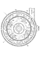
- the suction pump mechanism Y includes a main casing 1 having a cylindrical outer peripheral wall 4 whose both end openings are closed by the front wall 2 and the rear wall 3, and the main casing A rotor 5 concentrically and rotatably provided inside 1; a cylindrical stator 7 concentrically fixed to the front wall 2 inside the body casing 1; and a rotor 5
- the pump drive motor M3 and the like are provided.
- a plurality of rotary wings 6 project forward on the front wall 2 side (left side in FIG. 5) and are equally spaced circumferentially It is provided integrally with the rotor 5 in the state of being lined up.
- the cylindrical stator 7 is provided with a plurality of through holes 7 a and 7 b arranged in the circumferential direction, and the stator 7 is on the front side (left side in FIG. 5) of the rotor 5 and radially inside of the rotor 6.
- An annular wing chamber 8 is formed between the stator 7 and the outer peripheral wall 4 of the main body casing 1 so as to be fixed and disposed on the front wall 2.
- FIG. 5 to FIG. 7 there is a supply port 11 for suctioning and introducing the pre-mixture Fp in which the powder P and the liquid R are pre-mixed by the mixing mechanism 60 by the rotation of the rotor 6. And a position shifted to the outer peripheral side with respect to the central axis of the front wall portion 2 (axial center A3 of the main body casing 1).
- an annular groove 10 is formed on the inner surface of the front wall 2 of the main body casing 1, and a supply port 11 is provided in communication with the annular groove 10.
- the cylindrical discharge portion 12 discharging the slurry F generated by mixing the powder P and the liquid R is the periphery of the cylindrical outer peripheral wall 4 of the main body casing 1. It extends in a tangential direction of the outer peripheral wall 4 and is in communication with the wing chamber 8 at one point in the direction.
- the slurry F discharged from the discharge unit 12 is supplied to the recirculation mechanism unit 70 through the discharge passage 18, and is a separation unit of the recirculation mechanism unit 70.
- An inlet 17 for circulatingly supplying undissolved slurry Fr in which air bubbles are separated in the cylindrical container 71 into the main body casing 1 through the circulation passage 16 is a central portion of the front wall 2 of the main body casing 1 (shaft center A3 And concentrically).
- the partition plate 15 that divides the inner peripheral side of the stator 7 into the supply chamber 13 on the front wall 2 side and the introduction chamber 14 on the rotor 5 side is the front side of the rotor 5.
- the rotor 5 is integrally rotated with the rotor 5, and a scraping blade 9 is provided on the front wall 2 side of the partition plate 15.
- a plurality of scraping wings 9 are provided concentrically at equal intervals in the circumferential direction (four in FIG. 7), and the rotor 5 with each scraping wing 9 advancing its tip 9 T into the annular groove 10. It is arranged to be able to go around integrally with it.
- the supply chamber 13 and the introduction chamber 14 are configured to be in communication with the wing chamber 8 via the plurality of through holes 7 a and 7 b of the stator 7, the supply port 11 communicates with the supply chamber 13, and the introduction port 17 is an introduction It is configured to communicate with the chamber 14.
- the supply chamber 13 and the wing chamber 8 are communicated with each other at a plurality of supply chamber side through holes 7a arranged at equal intervals in the circumferential direction at a portion of the stator 7 facing the supply chamber 13, and the introduction chamber
- the vane chamber 14 and the wing chamber 8 communicate with each other at a portion of the stator 7 facing the introduction chamber 14 through a plurality of introduction chamber side through holes 7 b arranged at equal intervals in the circumferential direction.
- the rotor 5 is configured in such a shape that the front surface thereof is expanded in a substantially truncated cone shape, and the rotors 6 are arranged at equal intervals on the outer peripheral side with the plurality of rotary wings 6 projecting forward. It is provided.
- ten rotary wings 6 are disposed at equal intervals in the circumferential direction.
- the rotary wing 6 is formed so as to protrude from the outer circumferential side of the rotor 5 to the inner circumferential side so as to be inclined rearward in the rotational direction from the inner circumferential side toward the outer circumferential side.
- the inner diameter of the housing 7 is slightly larger than the outer diameter of the stator 7.
- the rotor 5 is connected to a drive shaft 19 of a pump drive motor M3 inserted into the main body casing 1 through the rear wall 3 in a state where the rotor 5 is positioned concentrically with the main body casing 1 in the main body casing 1 , And are rotationally driven by the pump drive motor M3.
- the rotor 5 is rotationally driven in such a direction that the tip of the rotor 6 is on the front side in the axial center direction view (view VI-VI in FIG. 5 as shown in FIG. 6).
- a so-called local boiling (cavitation) is generated on the rear surface (rear surface) 6a in the rotational direction.
- the partition plate 15 is formed in a generally funnel shape having an outer diameter slightly smaller than the inner diameter of the stator 7.
- the funnel-shaped partition plate 15 is provided with a funnel-shaped portion 15b opened at a cylindrical sliding contact portion 15a whose top projects in a cylindrical shape at its central portion, and the funnel-shaped portion 15b
- An annular flat plate portion 15c which is in a state of being orthogonal to the axial center A3 of the main body casing 1 on both the front and rear surfaces is formed on the outer peripheral portion of the above. Then, as shown in FIGS.
- a plurality of partition plates 15 are arranged at equal intervals in the circumferential direction in a posture in which the cylindrical sliding contact portion 15a at the top faces the front wall 2 side of the main body casing 1 It is attached to the attachment part 5a of the front surface of the rotor 5 via the space
- the stirring blade 21 is disposed on the rear wall 3 side of the main body casing 1.
- the four stirring blades 21 are configured to rotate integrally with the rotor 5 when the rotor 5 is rotationally driven.
- a cylindrical inlet 17 is provided concentrically with the main body casing 1 at the center of the front wall 2 of the main body casing 1.
- the inlet port 17 is formed with a throttling portion 14a smaller in diameter than the inner diameter of the circulation passage 16 and smaller in diameter than the cylindrical sliding contact portion 15a of the partition plate 15 and having a smaller flow passage area.
- the rotation of the rotor 6 of the rotor 5 causes the slurry F to be discharged through the discharge portion 12 and the undissolved slurry Fr to be introduced through the throttling portion 14 a of the inlet 17.
- the suction pump mechanism The pressure in part Y is reduced.
- the main body casing 1 has the opening (inlet portion) opened in the main body casing 1 of the supply port 11 including a part in the circumferential direction of the annular groove 10 inside. It is provided in the front wall 2 so as to be located on the side of the opening of the inlet 17 with respect to the inside.
- the supply port 11 has a horizontal direction in which the axial center A2 is parallel to the axial center A3 of the main casing 1 and is orthogonal to the axial center A3 of the main casing 1 in a plan view (vertical view in FIG. 2 and FIG. 5).
- the downward inclination angle of the supply port 11 with respect to the horizontal direction is about 45 degrees as described above.
- the stator 7 is attached to the inner surface (surface facing the rotor 5) of the front wall 2 of the main body casing 1, and the front wall 2 of the main body casing 1 and the stator 7 It is fixed so that it may become one.
- the plurality of supply chamber side through holes 7a disposed in a portion facing the supply chamber 13 are formed in a substantially circular shape, and the plurality of supply chamber side through holes 7a are formed more than the flow passage area of the supply chamber 13.
- the total flow passage area is set to be small, and the plurality of introduction chamber side through holes 7 b disposed in a portion facing the introduction chamber 14 are formed in a substantially elliptical shape, and the flow passage of the introduction chamber 14
- the total flow passage area of the plurality of introduction chamber side through holes 7 b is set to be smaller than the area.
- each scraping blade 9 is formed in a rod shape, and the rod-like scraping blade 9 is viewed in the radial direction of the rotor 5 (view in FIG.
- the tip end side of the wing 9 is located on the front wall 2 side, and the tip side of the rod-like scraping wing 9 is viewed from the axial center direction of the rotor 5 (view from the front and back of FIG. 8A).
- the base end 9B of the rod-like scraping blade 9 is fixed so as to rotate integrally with the rotor 5 in an inclined posture positioned radially inward of the rotor 5, and the rotor 5 is viewed in the axial center direction (see FIG.
- the tip of the scraping blade 9 is rotationally driven in the direction (indicated by the arrow in FIG. 5 to FIG. 8) in FIG.
- the scraping blade 9 has a proximal end 9B fixed to the partition plate 15, an intermediate portion 9M exposed to the supply chamber 13, and a distal end 9T inserted (that is, advanced) into the annular groove 10. It is comprised in the rod shape equipped in series toward the front end from the proximal end.
- the base end 9B of the scraping blade 9 is formed in a substantially rectangular plate shape.
- the middle portion 9M of the scraping blade 9 is formed in a substantially triangular prism shape whose cross-sectional shape is substantially triangular (in particular, See Figure 6).
- one side surface 9m facing the front side in the rotational direction of the rotor 5 among the three side surfaces of the middle portion 9M of triangular column (hereinafter referred to as a dissipation surface).
- a dissipation surface There is a case where the rotor 5 is inclined forward toward the front in the rotational direction of the rotor 5 and is directed downward in the radial direction with respect to the radial direction of the rotor 5 (hereinafter referred to as obliquely outward) (In particular, refer to FIGS. 7 and 8).
- the rotor 5 is more than the tip 9 T in which the intermediate portion 9M exposed to the supply chamber 13 in the scraping blade 9 is fitted into the annular groove 10.
- the diffusion surface 9m which is located outward in the radial direction and faces the front in the rotational direction of the middle part 9M, inclines toward the front in the rotational direction of the rotor 5, and further It is inclined diagonally outward.
- the preliminary mixture Fp scraped out of the annular groove 10 by the tip 9 T of the scraping blade 9 is radially outside the rotor 5 in the supply chamber 13 by the diffusion surface 9 m of the middle portion 9 M of the scraping blade 9. It is guided to flow toward the other side.
- the tip 9 T of the scraping blade 9 has a substantially square pole shape whose cross-sectional shape is substantially rectangular, and the axial direction view of the rotor 5 (
- the outward facing side 9o of the four side faces directed radially outward of the rotor 5 is an inward facing inner face facing radially inward in the inner face of the annular groove 10.
- the side surface 9i facing inward in the radial direction of the rotor 5 is formed in an arc shape along the outside surface facing the outside in the radial direction on the inside surface of the annular groove 10 .
- the scraping surface 9f of the four side surfaces of the rectangular column-shaped tip 9T facing the front side in the rotational direction of the rotor 5 is in the form of a downward sloping shape inclined toward the front side in the rotational direction of the rotor 5, and the diameter of the rotor 5 It is configured to be directed radially outward with respect to the direction (hereinafter, may be described as oblique outward).
- the preliminary mixture Fp scraped out of the annular groove 10 by the tip 9T of the scraping wing 9 is directed radially outward of the rotor 5 by the scraping surface 9f of the tip 9T of the scraping wing 9 It will be discharged into the supply chamber 13.
- the tip end surface 9 t of the tip end 9 T of the scraping blade 9 is configured to be parallel to the bottom surface of the annular groove 10 in a state where the tip end 9 T is fitted into the annular groove 10.
- the base end portion of the scraping blade 9 A surface (rear surface) 9a which is a rear side in the rotational direction is formed at each of 9B, the intermediate portion 9M, and the tip portion 9T.
- Each of the base end portions 9B is formed in such a manner that the four scraping blades 9 configured as described above are arranged in the circumferential direction at intervals of 90 degrees at the central angle in the inclined posture as described above. It is fixed to the annular flat plate portion 15 c of the dividing plate 15.
- the partition plate 15 provided with the scraping blade 9 is attached to the attachment portion 5a of the front surface of the rotor 5 in a state of being separated from the front surface of the rotor 5 by the spacing member 20.
- the cylindrical sliding contact portion 15 a of the partitioning plate 15 is disposed in the main body casing 1 in a state in which the cylindrical sliding contact portion 15 a is slidably fitted in the introduction port 17.
- a tapered introduction chamber 14 is formed between the bulging front surface of the rotor 5 and the rear surface of the partition plate 15 such that the diameter of the introduction chamber 14 decreases in diameter toward the front wall 2 of the main casing 1. It is comprised so that it may connect with the introductory chamber 14 via the 15 cylindrical sliding contact part 15a.
- an annular supply chamber 13 communicating with the supply port 11 is formed between the front wall portion 2 of the main body casing 1 and the front surface of the partition plate 15.
- the partitioning plate 15 rotates integrally with the rotor 5 in a state where the cylindrical sliding contact portion 15 a is in sliding contact with the introduction port 17, and the rotor 5 and the partitioning plate 15 Even in the rotating state, a state in which the introduction port 17 communicates with the introduction chamber 14 via the cylindrical sliding contact portion 15 a of the dividing plate 15 is maintained.
- the recirculation mechanism unit (an example of the separation unit) 70 is configured to separate the solution by specific gravity in the cylindrical container 71, and as shown in FIG. 2, the discharge path from the discharge unit 12 of the suction pump mechanism unit Y
- the undissolved slurry Fr in a state containing the powder P which is not completely dissolved is supplied from the slurry F supplied through 18 into the circulation passage 16 and the slurry F in a state where the powder P is almost completely dissolved. It is comprised so that the discharge path 22 may each isolate
- the discharge passage 18 and the circulation passage 16 are respectively connected to the lower part of the cylindrical container 71, and the discharge passage 22 is connected to the upper part of the cylindrical container 71 and the tank 260 to which the slurry F is supplied.
- the recirculation mechanism unit 70 is disposed so that the introduction pipe to which the discharge passage 18 is connected is projected from the bottom of the cylindrical container 71 to the inside, and the discharge passage 22 is formed at the top of the cylindrical container 71 A discharge unit to be connected is provided, and a circulation unit to be connected to the circulation passage 16 is provided at the lower part, and a twist plate for swirling the flow of the slurry F discharged from the introduction pipe is disposed on the discharge upper end of the introduction pipe It is configured.
- the bubbles of the liquid R can be separated from the inside of the slurry F, and the bubbles of the liquid R can be supplied into the introduction chamber 14 in a state of being separated from the undissolved slurry Fr circulated and supplied to the circulation path 16.
- control unit C is configured to be able to control the number of rotations of the rotor 5 (rotating blades 6), and the pressure in the outlet region of the supply chamber side through hole 7a of the stator 7 and the introduction chamber side through hole 7b (throttle through hole) is
- the rotational speed of the rotor 6 is set so that the saturated vapor pressure of the liquid R (3.169 kPa in the case of water at 25 ° C.) over the entire circumference of the outlet area and the rotational speed at the set rotational speed
- the region in the wing chamber 8 immediately after passing at least the supply chamber side through hole 7a and the introduction chamber side through hole 7b of the stator 7 is continuous over the entire circumference in the wing chamber 8
- it is configured such that it can be formed as a micro bubble region in which a large number of micro bubbles (micro bubbles) of the liquid R are generated.
- the operation of the slurry production apparatus 200 will be described.
- the powder dry box 230 and the main body dry box 240 are operated to lower the dew point temperature.
- the cooling device 250 is operated.
- the air pressure in the inner box 232 is made positive (a state 2 to 3 Pa higher than the external pressure) and the air pressure in the outer box 231 is negative (2 3 Pa lower than the air pressure).
- the rotor 5 is rotated, and then the pump 261 is operated to supply only the liquid R of the tank 260.
- the operation of the suction pump mechanism Y is started.
- the mechanical seal on the rear surface of the rotor 5 is in close contact with the rotor 5, and liquid leakage from the rear surface of the rotor 5 can be prevented.
- the liquid R Due to the negative pressure suction force of the suction pump mechanism Y, the liquid R is continuously and quantitatively supplied to the mixing member 61 of the mixing mechanism 60 by a predetermined amount.
- a predetermined operation time has elapsed and the inside of the suction pump mechanism Y is in a negative pressure state (for example, a vacuum state of about ⁇ 0.06 MPa)
- the shutter valve 46 is opened.
- the expansion chamber 47 of the powder feeder X is brought into a negative pressure state (about -0.06 MPa), and the inside of the introduction portion 41 and the vicinity of the lower opening 31b of the hopper 31 Put pressure between them.
- the powder feeding device X is operated to feed the powder P from the feeder 220 to the hopper 31.
- the powder P stored in the hopper 31 is made from the lower opening 31b of the hopper 31 through the expansion chamber 47 of the quantitative supply unit 40 by the stirring action of the stirring blade 32A and the negative pressure suction force of the suction pump mechanism Y.
- a predetermined amount is continuously supplied to the mixing member 61 of the mixing mechanism 60 continuously. In this case, depending on the properties of the powder, a predetermined amount of powder may be supplied directly from the feeder 220 to the mixing mechanism 60 via the hopper 31 without using the quantitative supply unit 40.
- the supply speed of the feeder 220 is controlled to supply the powder to the mixing mechanism 60 so as not to exceed the powder processing capability of the mixing mechanism 60.
- Powder P is supplied from the mixing member 61 of the mixing mechanism 60 to the supply port 11 through the cylindrical portion 62 of the mixing member 61, and the liquid R flows through the annular slit 63 into a continuous hollow cylindrical vortex.
- the powder P and the liquid R are pre-mixed by the supply port 11 in the state, and the pre-mixture Fp is introduced into the annular groove 10 by the supply port 11.
- the powder discharge port 221 and the shutter valve 46 are closed to stop the suction of the powder P through the powder discharge pipe 45, and the suction pump mechanism from the powder supply device X Stop supplying powder to part Y. Then, the operation of the powder dry box 230 is stopped. The operation of the main body dry box 240 is continued.
- the scraping blade 9 provided concentrically in the partition plate 15 has the tip 9T fitted in the annular groove 10. Circulate in the state. Then, as shown by solid arrows in FIG. 5 and FIG. 6, the pre-mixture Fp flowing in the supply port 11 and introduced into the annular groove 10 is fitted in the annular groove 10 and the tip of the scraping blade 9 is circulated.
- the scraped out pre-mixture Fp scraped out by the portion 9T is, in general, arranged along the front surface of the funnel-shaped portion 15b of the partition plate 15 and the front surface of the annular flat portion 15c in the supply chamber 13. Flow through the supply chamber side through hole 7a of the stator 7 to flow into the wing chamber 8, flow through the wing chamber 8 in the rotational direction of the rotor 5, and discharge from the discharge portion 12 Be done.
- the pre-mixture Fp to be scraped off is mixed by being subjected to a shearing action from the scraping blade 9 and the supply chamber side through hole 7a.
- the dispersion of the powder P in the liquid R is performed better. Therefore, such a pre-mixture Fp can be supplied, and good dispersion of the powder P with respect to the liquid R can be expected in the wing chamber 8.
- the slurry F discharged from the discharge unit 12 is supplied to the recirculation mechanism unit 70 through the discharge passage 18, and in the recirculation mechanism unit 70, the undissolved slurry Fr in a state including the powder P not completely dissolved;
- the powder P is separated into the slurry F in a substantially completely dissolved state, and the bubbles of the liquid R are separated, and the undissolved slurry Fr is again supplied to the inlet 17 of the suction pump mechanism Y through the circulation path 16
- the slurry F is supplied to the tank 260 through the discharge passage 22.
- the undissolved slurry Fr is introduced into the introduction chamber 14 in a state where the flow rate is limited via the narrowed portion 14 a of the introduction port 17.
- the shear action by the plurality of rotating stirring blades 21 is further finely broken, and further, the shear action also occurs during the passage of the introduction chamber side through hole 7b. Ru.
- it is introduced into the wing chamber 8 in a state in which the flow rate is limited via the introduction chamber side through hole 7 b.
- the shearing action and the occurrence of local boiling (cavitation) on the rear surface 6 a (rear surface) on the rear side in the rotational direction of the rotary blade 6 are broken by the rotary blade 6 rotating at high speed.
- the slurry F in which the aggregates (powder) of the powder P are further reduced is mixed with the slurry F from the supply chamber 13 and discharged from the discharge unit 12.
- the pressure in the wing chamber 8 which is the exit region of the supply chamber side through hole 7a and the introduction chamber side through hole 7b of the stator 7 becomes lower than the saturation vapor pressure of the liquid R over the entire circumference by the control unit.
- the rotational speed of the rotary wing 6 is set, and the rotary wing 6 is rotated at the set rotational speed.
- region is below the saturated vapor pressure (3.169 kPa in the case of 25 degreeC water) of the liquid R over the whole circumference by rotation speed setting of the rotary blade 6
- the generation of micro bubbles (micro bubbles) due to the vaporization of the liquid R is promoted at least in the region inside the wing chamber 8 immediately after passing through the supply chamber side through hole 7a and the introduction chamber side through hole 7b of the stator 7.
- the region is continuously formed over the entire circumference in the wing chamber 8 as a micro-bubble region in which a large number of micro-bubbles are generated.
- the powder feeding device X is configured to include the feeder hopper 210, the feeder 220, the hopper 31, and the like.
- a form in which the powder P is sucked from a bag containing the powder P by a hose or the like is also possible.
- the opening of the powder supply device X is the opening of the bag and the suction port of the hose, and these openings are accommodated in the powder dry box 230.
- a configuration may be added to monitor the amount of the powder P to be introduced into the hopper 31.
- a sensor A capable of detecting the powder P is provided at a lower position of the lowermost end of the hopper 31 and at a predetermined position. The sensor A can detect that the powder P has been loaded into the hopper 31 from the lowermost end of the hopper 31 to a predetermined position.
- a control unit (not shown) slows the supply speed of the powder P from the feeder 220 to the hopper 31. As a result, excessive supply of the powder P to the hopper 31 can be suppressed, and clogging or the like of the powder P in the hopper 31 can be suppressed.
- a sensor B may be provided in the vicinity of the uppermost end of the hopper 31 to detect that the powder P has accumulated substantially in the entire hopper 31.
- the control unit (not shown) stops the supply of the powder P from the feeder 220 to the hopper 31. As a result, overflow of the powder P from the hopper 31 can be suppressed.
- the powder dry box 230 includes the outer box 231 and the inner box 232, and is configured by a double box.
- the powder dry box 230 may be configured by a single box.
- the powder dry box 230 may be configured of only the inner box 232.
- the dew point temperature of the inner box 232 is held, for example, at -70 ° C., as in the above embodiment.
- the pressure in the inner box 232 is maintained at a positive pressure, ie, about 2 to 3 Pa, for example, higher than the external pressure of the powder dry box 230.
- Body casing 2 Front wall 3: Back wall 4: Outer peripheral wall 5: Rotor 5 a: Mounting part 6: Rotor wings 7: Stator 7 a: Supply chamber side through hole 7 b: Introduction chamber side through hole 8: wing Chamber 9: Rubbing wing 9B: Base part 9M: Middle part 9T: Tip part 9a: Back face 9f: Scraping face 9i: Inward side 9m: Dissipation side 9o: Outward side 9t: Tip side 10: Annular groove 11: Supply port 12: Discharge part 13: Supply chamber 14: Introduction room 14a: Throttle part 15: Partition plate 15a: Tubular sliding contact part 15b: Funnel-like part 15c: Annular flat part 16: Circulation path 17: Introduction port 18: Discharge Path 19: Drive shaft 20: Space maintaining member 21: Agitating blade 22: Discharge passage 31: Hopper 31a: Upper opening 31b: Lower opening 32: Agitating mechanism 32A: Agitating blade 32B: Mounting member 32C: Transmission member 40
Landscapes
- Chemical & Material Sciences (AREA)
- Chemical Kinetics & Catalysis (AREA)
- Engineering & Computer Science (AREA)
- Dispersion Chemistry (AREA)
- General Chemical & Material Sciences (AREA)
- Electrochemistry (AREA)
- Manufacturing & Machinery (AREA)
- Condensed Matter Physics & Semiconductors (AREA)
- Inorganic Chemistry (AREA)
- General Physics & Mathematics (AREA)
- Physics & Mathematics (AREA)
- Materials Engineering (AREA)
- Battery Electrode And Active Subsutance (AREA)
- Mixers Of The Rotary Stirring Type (AREA)
- Secondary Cells (AREA)
- Accessories For Mixers (AREA)
- Feeding, Discharge, Calcimining, Fusing, And Gas-Generation Devices (AREA)
Abstract
Description
上記目的を達成するためのスラリー製造装置の特徴構成は、液体と粉体とを混合してスラリーを製造する混合装置と、前記混合装置に粉体を供給する粉体供給装置と、粉体用ドライボックスとを有し、前記粉体供給装置の開口部が前記粉体用ドライボックスに収納されている点にある。
本発明に係るスラリー製造装置の別の特徴構成は、前記粉体供給装置は、上側が開口したホッパと、前記ホッパに粉体を供給するフィーダとを有し、前記ホッパの開口部と前記フィーダの粉体排出口とが前記粉体用ドライボックスに収納されている点にある。
本発明に係るスラリー製造装置の別の特徴構成は、前記粉体供給装置は、前記フィーダに粉体を供給するフィーダホッパを有し、前記フィーダホッパのエア抜き口が前記粉体用ドライボックスに接続されている点にある。
本発明に係るスラリー製造装置の別の特徴構成は、前記混合装置を内部に収納する本体用ドライボックスを有する点にある。
本発明に係るスラリー製造装置の別の特徴構成は、前記本体用ドライボックスの露点温度が、前記粉体用ドライボックスの露点温度よりも高い点にある。
本発明に係るスラリー製造装置の別の特徴構成は、前記本体用ドライボックスの内部に、前記混合装置を冷却する冷却装置が収納されている点にある。
本発明に係るスラリー製造装置において、前記混合装置が遠心式分散混合ポンプであると好適である。
本発明に係るスラリー製造装置は、全固体電池の製造に用いられる正極活物質層スラリー、負極活物質スラリー、または固体電解質スラリーを製造する場合に好適に適用可能である。
本発明に係るスラリー製造装置は、前記粉体が硫化物固体電解質を含有する場合に好適に適用可能である。
上記目的を達成するためのスラリー製造装置の運転方法の特徴構成は、スラリー製造装置の運転方法であって、
前記スラリー製造装置は、液体と粉体とを混合してスラリーを製造する混合装置と、前記混合装置に粉体を供給する粉体供給装置と、粉体用ドライボックスと、前記混合装置を内部に収納する本体用ドライボックスを有し、前記粉体供給装置の開口部が前記粉体用ドライボックスに収納されており、
前記粉体供給装置から前記混合装置に粉体を供給する間は、前記粉体用ドライボックスと前記本体用ドライボックスの両方を運転し、
前記粉体供給装置から前記混合装置への粉体の供給が完了すると、前記粉体用ドライボックスの運転を停止し、前記本体用ドライボックスの運転を行う、点にある。
なお、粉体の供給が完了した場合とは、粉体供給装置から混合装置への粉体の供給が完了し、粉体供給装置に粉体が残っていない場合、及び、粉体供給装置に粉体が残っているものの、粉体供給装置から混合装置内への粉体の供給が停止され、外部からの粉体供給装置への粉体の供給口が蓋及びシャッタ等により塞がれて粉体供給装置が密閉されている場合を含む。
内側ボックス232の露点温度を外側ボックス231の露点温度よりも低くすることで、外側ボックス231で露点温度を低く調整し、内側ボックス232でさらに露点温度を低く調整して段階的に露点温度を低下できる。これにより、内側ボックス232での低い露点温度の調整が容易であり、ランニングコストを低下できる。
なお、外側ボックス231及び内側ボックス232の露点温度は上記のものに限定されず、粉体Pの性状等に応じて適宜設定可能である。
また、上記の通り、外側ボックス231の気圧を外気圧よりも陰圧とすることで、外側ボックス231内に収容されている臭気が外側に拡散するのを抑制できる。また、内側ボックス232の気圧が外側ボックス231の気圧よりも高いため、内側ボックス232に向かう空気の流れが阻止され、内側ボックス232の露点温度の調整が容易であり、例えば-70℃以下に保持できる。
なお、粉体の供給が完了した場合とは、粉体供給装置Xから吸引ポンプ機構部(混合装置)Yへの粉体の供給が完了し、粉体供給装置Xに粉体が残っていない場合、及び、粉体供給装置Xに粉体が残っているものの、粉体供給装置Xから吸引ポンプ機構部Y内への粉体の供給が停止され、外部からの粉体供給装置Xへの粉体の供給口が図示しない蓋及びシャッタ等により塞がれて粉体供給装置Xが密閉されている場合を含む。このように粉体供給装置Xに粉体が残っていても粉体供給装置Xを密閉することで、粉体が湿気を吸収してしまうのを抑制できる。
図2に示すように、粉体供給装置Xは、上部開口部31aから受け入れた粉体Pを下部開口部31bから排出させるホッパ31と、ホッパ31内の粉体Pを攪拌する攪拌機構32と、ホッパ31の上部開口部31aが大気開放された状態で、下部開口部31bの下流側に接続された吸引ポンプ機構部Yの吸引により下部開口部31bに作用する負圧吸引力によって、下部開口部31bから排出された粉体Pを吸引ポンプ機構部Yに定量供給する容積式の定量供給部40とを備えている。
具体的には、ホッパ31の下部開口部31bに接続される導入部41と、供給口43a及び排出口43bを備えたケーシング43と、ケーシング43内に回転可能に配設された計量回転体44と、計量回転体44を回転駆動する計量回転体駆動モータM2とを備えて構成される。
図3及び図4に示すように、ケーシング43の上面には、導入部41のスリット状の開口に対応したスリット状の供給口43aが設けられ、ホッパ31の下部開口部31bからの粉体Pをケーシング43内に供給可能に構成されている。傾斜状に配置されたケーシング43の下方側の側面(図3において右側面)の下部には、計量回転体44にて定量供給された粉体Pを膨張室47を介して下流側の吸引ポンプ機構部Yに排出する排出口43bが設けられ、その排出口43bには、粉体排出管45が接続されている。当該膨張室47は、供給口43aから計量回転体44の粉体収容室44bに供給された粉体Pが定量供給されるケーシング43内の位置に設けられ、排出口43bから作用する負圧吸引力によって、供給口43aよりも低圧に維持される(例えば、-0.06MPa程度)。すなわち、排出口43bは、吸引ポンプ機構部Yの一次側に接続されることによって、負圧吸引力が膨張室47に作用し供給口43aよりも低圧状態に維持されるようにしている。計量回転体44の回転に伴って、各粉体収容室44bの状態が負圧状態(例えば、-0.06MPa程度)と当該負圧状態よりも高圧の状態に変化するように構成されている。
上記では、ホッパ31内の粉体Pは、定量供給部40を介して吸引ポンプ機構部Yに供給される。ただし、付着性を有する粉体Pの場合には、定量供給部40を用いず、例えば、フィーダ220から、その回転を制御して、ホッパ31を介して直接に吸引ポンプ機構部Yに供給するようにしてもよい。この場合、例えばホッパ31と吸引ポンプ機構部Yとを直接つなぐ通路が別途形成されており、粉体Pの性状に応じて、ホッパ31から定量供給部40を介して吸引ポンプ機構部Yへ粉体Pを供給するか、あるいは、ホッパ31から吸引ポンプ機構部Yへ粉体Pを供給するかを切り換え可能に構成されていると好ましい。
図1及び図2に示すように、タンク260は、タンク260内の液体Rを設定流量で吸引ポンプ機構部Yの供給口11に連続的に供給するように構成されている。よって、タンク260は、液体Rを吸引ポンプ機構部Yに供給する溶媒供給源として機能する。また、タンク260には、再循環機構部70から排出路22を介してスラリーFが供給される。よって、タンク260は、スラリーFを回収するスラリー回収源として機能する。
タンク260には、タンク260とミキシング機構60とを接続し、液体Rが内部を通過する溶媒供給管52と、溶媒供給管52に設けられ、タンク260から溶媒供給管52を介してミキシング機構60に液体Rを送出するポンプ261と、タンク260から溶媒供給管52に送出される液体Rの流量を設定流量に調整する流量調整バルブ(図示せず)とを備えている。
このミキシング部材61は、円筒状の供給口11よりも小径に構成されて、供給口11との間に環状のスリット63を形成すべく供給口11に挿入状態で配設される筒状部62、及び、環状のスリット63に全周にわたって連通する状態で供給口11の外周部に環状流路64を形成する環状流路形成部65を備えて構成されている。
ミキシング部材61には、粉体排出管45が筒状部62に連通する状態で接続されると共に、溶媒供給管52が環状流路64に対して液体Rを接線方向に供給するように接続される。
粉体排出管45、ミキシング部材61の筒状部62及び供給口11は、それらの軸心A2を供給方向が下向きとなる傾斜姿勢(水平面(図2の左右方向)に対する角度が45度程度)となるように傾斜させて配置されている。
従って、円筒状の供給口11により、粉体Pと液体Rとが均等に予備混合され、その予備混合物Fpが吸引ポンプ機構部Yの供給室13内に吸引導入される。
図2、図5~図8に基づいて、吸引ポンプ機構部Yについて説明を加える。
図5に示すように、吸引ポンプ機構部Yは、両端開口が前壁部2と後壁部3とで閉じられた円筒状の外周壁部4を備えた本体ケーシング1を備え、その本体ケーシング1の内部に同心状で回転駆動自在に設けられたロータ5と、その本体ケーシング1の内部に同心状で前壁部2に固定配設された円筒状のステータ7と、ロータ5を回転駆動するポンプ駆動モータM3等を備えて構成されている。
円筒状のステータ7には、複数の透孔7a,7bが周方向に夫々並べて備えられ、そのステータ7が、ロータ5の前方側(図5の左側)で且つ回転翼6の径方向の内側に位置させて前壁部2に固定配設されて、そのステータ7と本体ケーシング1の外周壁部4との間に、回転翼6が周回する環状の翼室8が形成される。
図5、図7に示すように、本体ケーシング1の前壁部2の内面に環状溝10が形成され、環状溝10と連通する状態で供給口11が設けられている。
図5及び図6に示すように、粉体Pと液体Rとが混合されて生成されたスラリーFを吐出する円筒状の吐出部12が、本体ケーシング1の円筒状の外周壁部4の周方向における1箇所に、その外周壁部4の接線方向に延びて翼室8に連通する状態で設けられている。
又、図5~図7に示すように、ステータ7の内周側を前壁部2側の供給室13とロータ5側の導入室14とに区画する区画板15が、ロータ5の前方側に当該ロータ5と一体回転する状態で設けられると共に、区画板15の前壁部2側に掻出翼9が設けられている。掻出翼9は、同心状に、周方向において均等間隔で複数(図7では、4つ)備えられ、各掻出翼9がその先端部9Tを環状溝10内に進入した状態でロータ5と一体的に周回可能に配設されている。
具体的には、供給室13と翼室8とは、ステータ7における供給室13に臨む部分に周方向に等間隔で配設された複数の供給室側透孔7aにて連通され、導入室14と翼室8とは、ステータ7における導入室14に臨む部分に周方向に等間隔で配設された複数の導入室側透孔7bにて連通されている。
図5に示すように、ロータ5は、その前面が概ね円錐台状に膨出する形状に構成されると共に、その外周側に、複数の回転翼6が前方に突出する状態で等間隔に並べて設けられている。なお、図6では、周方向に等間隔に10個の回転翼6が配設されている。また、この回転翼6は、内周側から外周側に向かうに連れて、回転方向後方に傾斜するようにロータ5の外周側から内周側に突出形成されており、回転翼6の先端部の内径は、ステータ7の外径よりも若干大径に形成されている。
このロータ5が、本体ケーシング1内において本体ケーシング1と同心状に位置する状態で、後壁部3を貫通して本体ケーシング1内に挿入されたポンプ駆動モータM3の駆動軸19に連結されて、そのポンプ駆動モータM3により回転駆動される。
このロータ5が、その軸心方向視(図6に示すような図5のVI-VI方向視)において回転翼6の先端部が前側となる向きに回転駆動されることにより、回転翼6の回転方向の後側となる面(背面)6aには、いわゆる局所沸騰(キャビテーション)が発生するように構成されている。
そして、図5及び図6に示すように、この区画板15が、頂部の筒状摺接部15aが本体ケーシング1の前壁部2側を向く姿勢で、周方向に等間隔を隔てた複数箇所(この実施形態では、4箇所)に配設された間隔保持部材20を介して、ロータ5の前面の取付部5aに取り付けられる。
掻出翼9は、区画板15に固定される基端部9B、供給室13に露呈する状態となる中間部9M、環状溝10に嵌め込まれる(即ち、進入する)状態となる先端部9Tを基端から先端に向けて一連に備えた棒状に構成されている。
図6、図7、図8(a)及び(b)に示すように、掻出翼9の中間部9Mは、横断面形状が概ね三角形状になる概ね三角柱状に構成されている(特に、図6参照)。そして、掻出翼9が上述の如き傾斜姿勢で設けられることにより、三角柱状の中間部9Mの三側面のうちのロータ5の回転方向前側を向く一側面9m(以下、放散面と記載する場合がある)は、ロータ5の回転方向前側に向けて傾斜する前下がり状で、しかも、ロータ5の径方向に対して径方向外方側に向く(以下、斜め外向きと記載する場合がある)ように構成されている(特に、図7、図8参照)。
又、四角柱状の先端部9Tの四側面のうちの、ロータ5の回転方向前側を向く掻き出し面9fは、ロータ5の回転方向前側に向けて傾斜する前下がり状で、しかも、ロータ5の径方向に対して径方向外方側に向く(以下、斜め外向きと記載する場合がある)になるように構成されている。
これにより、掻出翼9の先端部9Tにより環状溝10から掻き出された予備混合物Fpは、掻出翼9の先端部9Tの掻き出し面9fにより、ロータ5の径方向外方側に向けて供給室13内に放出されることになる。
更に、掻出翼9の先端部9Tの先端面9tは、その先端部9Tが環状溝10に嵌め込まれた状態で環状溝10の底面と平行になるように構成されている。
すると、ロータ5の膨出状の前面と区画板15の後面との間に、本体ケーシング1の前壁部2側ほど小径となる先細り状の導入室14が形成され、導入口17が区画板15の筒状摺接部15aを介して導入室14に連通するように構成されている。
又、本体ケーシング1の前壁部2と区画板15の前面との間に、供給口11に連通する環状の供給室13が形成される。
再循環機構部(分離部の一例)70は、円筒状容器71内において比重によって溶解液を分離するように構成され、図2に示すように、吸引ポンプ機構部Yの吐出部12から吐出路18を通して供給されるスラリーFから、完全に溶解していない粉体Pを含む可能性がある状態の未溶解スラリーFrを循環路16に、粉体Pが略完全に溶解した状態のスラリーFを排出路22にそれぞれ分離するように構成されている。吐出路18及び循環路16は、夫々、円筒状容器71の下部に接続され、排出路22は、円筒状容器71の上部とスラリーFの供給先であるタンク260とに接続される。
ここで、再循環機構部70は、図示しないが、吐出路18が接続される導入パイプを円筒状容器71の底面から内部に突出して配設し、円筒状容器71の上部に排出路22に接続される排出部を備えるとともに、下部に循環路16に接続される循環部を備え、導入パイプの吐出上端に、導入パイプから吐出されるスラリーFの流れを旋回させる捻り板を配設して構成されている。これにより、スラリーF内から液体Rの気泡を分離して、循環路16に循環供給される未溶解スラリーFrから液体Rの気泡を分離した状態で導入室14内に供給することができる。
特に制御部Cは、ロータ5(回転翼6)の回転数を制御可能に構成され、ステータ7の供給室側透孔7a及び導入室側透孔7b(絞り透孔)の出口領域の圧力が当該出口領域の全周に亘って液体Rの飽和蒸気圧(25℃の水の場合、3.169kPa)以下となるように回転翼6の回転数を設定し、当該設定された回転数で回転翼6を回転することで、少なくともステータ7の供給室側透孔7a及び導入室側透孔7bを通過した直後の翼室8内の領域を、翼室8内の全周に亘って連続して、液体Rの微細気泡(マイクロバブル)が多数発生した微細気泡領域として形成させることができるように構成されている。
次に、このスラリー製造装置200の動作について説明する。
まず、粉体用ドライボックス230及び本体用ドライボックス240を運転して、露点温度を低下させる。冷却装置250を運転する。また、除湿ユニット233の調整により、内側ボックス232の気圧を陽圧(外気圧より2~3Pa程度高い状態)とし、外側ボックス231の気圧を陰圧(外気圧より2~3Pa程度低い状態)とする。
次に、シャッタバルブ46を閉止して粉体排出管45を介する粉体Pの吸引を停止した状態で、ロータ5を回転させた後に、ポンプ261作動させてタンク260の液体Rのみを供給し、吸引ポンプ機構部Yの運転を開始する。ロータ5を回転させた後に液体Rを吸引ポンプ機構部Yに供給することで、ロータ5の背面のメカニカルシールがロータ5に密着し、ロータ5背面からの液漏れを防止することができる。
吸引ポンプ機構部Yの負圧吸引力により、液体Rが、ミキシング機構60のミキシング部材61に所定量ずつ連続的に定量供給される。
所定の運転時間が経過して、吸引ポンプ機構部Y内が、負圧状態(例えば、-0.06MPa程度の真空状態)となると、シャッタバルブ46を開放する。これによって、粉体供給装置Xの膨張室47を負圧状態(-0.06MPa程度)とし、導入部41の内部及びホッパ31の下部開口部31b近傍を当該負圧状態と大気圧状態との間の圧力状態にする。
この場合、粉体の性状によっては、定量供給部40を使用せず、フィーダ220からホッパ31を介して直接的にミキシング機構60へ所定量の粉体を供給してもよい。このとき、ミキシング機構60の粉体処理能力を超えないように、フィーダ220の供給速度を制御して粉体をミキシング機構60に供給する。
ミキシング機構60のミキシング部材61からは、粉体Pがミキシング部材61の筒状部62を通して供給口11に供給されると共に、液体Rが、環状のスリット63を通して切れ目のない中空円筒状の渦流の状態で供給口11に供給され、供給口11により、粉体Pと液体Rとが予備混合され、その予備混合物Fpが環状溝10に導入される。
すると、図5及び図6において実線矢印にて示すように、供給口11を流動して環状溝10に導入された予備混合物Fpは、環状溝10に嵌め込まれて周回する掻出翼9の先端部9Tにより掻き出され、その掻き出された予備混合物Fpは、概略的には、供給室13内を区画板15における漏斗状部15bの前面と環状平板部15cの前面とに沿いながらロータ5の回転方向に流動し、更に、ステータ7の供給室側透孔7aを通過して翼室8に流入し、その翼室8内をロータ5の回転方向に流動して、吐出部12から吐出される。
つまり、供給室13内の予備混合物Fpにせん断力を作用させることができるので、掻き出される予備混合物Fpは、掻出翼9及び供給室側透孔7aからせん断作用を受けて混合されることにより、液体Rに対する粉体Pの分散がより良好に行われることとなる。よって、このような予備混合物Fpを供給することができ、翼室8内において液体Rに対する粉体Pの良好な分散を期待することができる。
これにより、回転翼6の回転数設定により、当該出口領域である翼室8内の圧力は、その全周に亘って液体Rの飽和蒸気圧(25℃の水の場合、3.169kPa)以下となるから、少なくともステータ7の供給室側透孔7a及び導入室側透孔7bを通過した直後の翼室8内の領域では、液体Rの気化による微細気泡(マイクロバブル)の発生が促進され、当該領域が、翼室8内の全周に亘って連続して微細気泡が多数発生した微細気泡領域として形成される状態となる。
例えば、ホッパ31の最下端から所定位置の下部に粉体Pを検出可能なセンサAを設ける。センサAにより、ホッパ31の最下端から所定位置まで粉体Pがホッパ31に投入されていることが検出できる。センサAが粉体Pを検出した場合には、図示しない制御部がフィーダ220からホッパ31への粉体Pの供給速度を遅くする。これにより、ホッパ31に過度に粉体Pが供給されるのを抑制し、ホッパ31での粉体Pの詰まり等を抑制できる。
さらに、ホッパ31の概ね全体に粉体Pが溜まったことを検出するセンサBを、ホッパ31の最上端近傍に設けてもよい。センサBが粉体Pを検出した場合には、図示しない制御部がフィーダ220からホッパ31への粉体Pの供給を停止する。これにより、ホッパ31から粉体Pが溢れてしまうのを抑制できる。
2 :前壁部
3 :後壁部
4 :外周壁部
5 :ロータ
5a:取付部
6 :回転翼
7 :ステータ
7a:供給室側透孔
7b:導入室側透孔
8 :翼室
9 :掻出翼
9B:基端部
9M:中間部
9T:先端部
9a:背面
9f:掻き出し面
9i:内向き側面
9m:放散面
9o:外向き側面
9t:先端面
10:環状溝
11:供給口
12:吐出部
13:供給室
14:導入室
14a:絞り部
15:区画板
15a:筒状摺接部
15b:漏斗状部
15c:環状平板部
16:循環路
17:導入口
18:吐出路
19:駆動軸
20:間隔保持部材
21:攪拌羽根
22:排出路
31:ホッパ
31a:上部開口部
31b:下部開口部
32:攪拌機構
32A:攪拌羽根
32B:取付部材
32C:伝動部材
40:定量供給部
41:導入部
42:開口閉鎖部材
43:ケーシング
43a:供給口
43b:排出口
44:計量回転体
44a:板状隔壁
44b:粉体収容室
45:粉体排出管
46:シャッタバルブ
47:膨張室
48:駆動軸
49:円盤部材
52:溶媒供給管
60:ミキシング機構
61:ミキシング部材
62:筒状部
63:スリット
64:環状流路
65:環状流路形成部
70:再循環機構部
71:円筒状容器
100:分散システム
200:スラリー製造装置
210:フィーダホッパ
211:エア抜き口
220:フィーダ
221:粉体排出口
230:粉体用ドライボックス
231:外側ボックス
232:内側ボックス
233:除湿ユニット
240:本体用ドライボックス
250:冷却装置
260:タンク
261:ポンプ
270:圧力抜き部
271:フィルタ
280:架台
A1:中心軸
A2:軸心
A3:軸心
C :制御部
F :スラリー
Fp:予備混合物
Fr:未溶解スラリー
M1:羽根駆動モータ
M2:計量回転体駆動モータ
M3:ポンプ駆動モータ
M4:タンク撹拌モータ
P :粉体
R :液体
V :概略
X :粉体供給装置
Y :吸引ポンプ機構部(混合装置)
Claims (10)
- 液体と粉体とを混合してスラリーを製造する混合装置と、前記混合装置に粉体を供給する粉体供給装置と、粉体用ドライボックスとを有し、前記粉体供給装置の開口部が前記粉体用ドライボックスに収納されているスラリー製造装置。
- 前記粉体供給装置は、上側が開口したホッパと、前記ホッパに粉体を供給するフィーダとを有し、前記ホッパの開口部と前記フィーダの粉体排出口とが前記粉体用ドライボックスに収納されている請求項1に記載のスラリー製造装置。
- 前記粉体供給装置は、前記フィーダに粉体を供給するフィーダホッパを有し、前記フィーダホッパのエア抜き口が前記粉体用ドライボックスに接続されている請求項2に記載のスラリー製造装置。
- 前記混合装置を内部に収納する本体用ドライボックスを有する請求項1から3のいずれか1項に記載のスラリー製造装置。
- 前記本体用ドライボックスの露点温度が、前記粉体用ドライボックスの露点温度よりも高い請求項4に記載のスラリー製造装置。
- 前記本体用ドライボックスの内部に、前記混合装置を冷却する冷却装置が収納されている請求項4又は5に記載のスラリー製造装置。
- 前記混合装置が遠心式分散混合ポンプである請求項1から6のいずれか1項に記載のスラリー製造装置。
- 前記スラリーが、全固体電池の製造に用いられる正極活物質層スラリー、負極活物質スラリー、または固体電解質スラリーである請求項1から7のいずれか1項に記載のスラリー製造装置。
- 前記粉体が、硫化物固体電解質を含有する請求項1から8のいずれか1項に記載のスラリー製造装置。
- スラリー製造装置の運転方法であって、
前記スラリー製造装置は、液体と粉体とを混合してスラリーを製造する混合装置と、前記混合装置に粉体を供給する粉体供給装置と、粉体用ドライボックスと、前記混合装置を内部に収納する本体用ドライボックスとを有し、前記粉体供給装置の開口部が前記粉体用ドライボックスに収納されており、
前記粉体供給装置から前記混合装置に粉体を供給する間は、前記粉体用ドライボックスと前記本体用ドライボックスの両方を運転し、
前記粉体供給装置から前記混合装置への粉体の供給が完了すると、前記粉体用ドライボックスの運転を停止し、前記本体用ドライボックスの運転を行う、スラリー製造装置の運転方法。
Priority Applications (5)
| Application Number | Priority Date | Filing Date | Title |
|---|---|---|---|
| EP18874017.9A EP3705175B1 (en) | 2017-10-30 | 2018-09-03 | Slurry manufacturing device and operating method for slurry manufacturing device |
| KR1020207007248A KR102507484B1 (ko) | 2017-10-30 | 2018-09-03 | 슬러리제조장치, 및 슬러리제조장치의 운전방법 |
| CN201880057029.XA CN111246933A (zh) | 2017-10-30 | 2018-09-03 | 浆料制造装置及浆料制造装置的运转方法 |
| JP2019549901A JP7155140B2 (ja) | 2017-10-30 | 2018-09-03 | スラリー製造装置、およびスラリー製造装置の運転方法 |
| US16/818,739 US11547974B2 (en) | 2017-10-30 | 2020-03-13 | Slurry manufacturing device and operating method for slurry manufacturing device |
Applications Claiming Priority (2)
| Application Number | Priority Date | Filing Date | Title |
|---|---|---|---|
| JP2017209325 | 2017-10-30 | ||
| JP2017-209325 | 2017-10-30 |
Related Child Applications (1)
| Application Number | Title | Priority Date | Filing Date |
|---|---|---|---|
| US16/818,739 Continuation US11547974B2 (en) | 2017-10-30 | 2020-03-13 | Slurry manufacturing device and operating method for slurry manufacturing device |
Publications (1)
| Publication Number | Publication Date |
|---|---|
| WO2019087559A1 true WO2019087559A1 (ja) | 2019-05-09 |
Family
ID=66331712
Family Applications (1)
| Application Number | Title | Priority Date | Filing Date |
|---|---|---|---|
| PCT/JP2018/032580 Ceased WO2019087559A1 (ja) | 2017-10-30 | 2018-09-03 | スラリー製造装置、およびスラリー製造装置の運転方法 |
Country Status (7)
| Country | Link |
|---|---|
| US (1) | US11547974B2 (ja) |
| EP (1) | EP3705175B1 (ja) |
| JP (1) | JP7155140B2 (ja) |
| KR (1) | KR102507484B1 (ja) |
| CN (1) | CN111246933A (ja) |
| TW (1) | TWI683940B (ja) |
| WO (1) | WO2019087559A1 (ja) |
Cited By (4)
| Publication number | Priority date | Publication date | Assignee | Title |
|---|---|---|---|---|
| JP2021168290A (ja) * | 2020-04-08 | 2021-10-21 | 石鴻偉 | 電池磁極片加工用のペースト混合撹拌装置 |
| CN114728246A (zh) * | 2020-02-10 | 2022-07-08 | 日本斯频德制造株式会社 | 分散装置及粉体供给部件 |
| JP2022175899A (ja) * | 2021-05-14 | 2022-11-25 | 三菱鉛筆株式会社 | 電極用分散体の製造方法 |
| JP2024047578A (ja) * | 2022-09-26 | 2024-04-05 | 月島機械株式会社 | 金属化合物の微粒子の製造装置、金属化合物の微粒子の製造システム |
Families Citing this family (10)
| Publication number | Priority date | Publication date | Assignee | Title |
|---|---|---|---|---|
| WO2021132465A1 (ja) * | 2019-12-27 | 2021-07-01 | ライオン株式会社 | ペースト状製剤の製造システム及びペースト状製剤の製造方法 |
| IT202000023272A1 (it) * | 2020-10-02 | 2022-04-02 | Ats S R L | Impianto per la micronizzazione e miscelazione di un prodotto a base di pigmenti |
| CN115869794B (zh) | 2021-09-23 | 2024-06-25 | 深圳市尚水智能股份有限公司 | 一种用于固液混合及分散的装置及设备 |
| US12350632B2 (en) | 2021-10-13 | 2025-07-08 | Shangshui Smartech Ltd. | Impeller assembly and mixing apparatus |
| EP4536388A1 (en) * | 2022-06-06 | 2025-04-16 | Genentech Inc. | Contained single-use powder induction system and method of use |
| WO2024058491A1 (ko) * | 2022-09-15 | 2024-03-21 | 주식회사 엘지에너지솔루션 | 제어 인자 산출 장치 및 그의 동작 방법 |
| JPWO2024106295A1 (ja) * | 2022-11-18 | 2024-05-23 | ||
| CN117358128A (zh) * | 2023-09-15 | 2024-01-09 | 苏州信敏惠纳米科技有限公司 | 一种高稳定性多元复合导电浆料的制备设备及其制备方法 |
| CN117018989B (zh) * | 2023-10-10 | 2023-12-26 | 长沙邦盛新能源有限公司 | 一种复合磷酸铁锂正极材料品混系统及工艺 |
| CN118949804B (zh) * | 2024-10-17 | 2025-01-10 | 广东维品承科技有限公司 | 一种粉液混合装置 |
Citations (6)
| Publication number | Priority date | Publication date | Assignee | Title |
|---|---|---|---|---|
| JPS5625216B2 (ja) | 1978-06-30 | 1981-06-11 | ||
| JPH0522378U (ja) * | 1991-08-30 | 1993-03-23 | 株式会社三陽電機製作所 | 粉体供給装置 |
| JPH0716442A (ja) * | 1993-06-30 | 1995-01-20 | Matsue Stainless Kosakusho:Kk | 高分子材料の溶解方法及びその装置 |
| JP2006341191A (ja) * | 2005-06-09 | 2006-12-21 | Osaka Seimitsu Kk | 粉体供給装置 |
| JP2015005372A (ja) * | 2013-06-19 | 2015-01-08 | 出光興産株式会社 | 硫化物系固体電解質の製造方法 |
| JP2015035344A (ja) * | 2013-08-09 | 2015-02-19 | 独立行政法人産業技術総合研究所 | カーボンを含有したペーストの製造方法 |
Family Cites Families (12)
| Publication number | Priority date | Publication date | Assignee | Title |
|---|---|---|---|---|
| US3326536A (en) * | 1962-05-09 | 1967-06-20 | Dow Chemical Co | Mixing apparatus |
| JPS5234591B2 (ja) * | 1972-02-10 | 1977-09-03 | ||
| JPS51145966A (en) * | 1975-06-11 | 1976-12-15 | Kurita Water Ind Ltd | Powder dispersing apparatus |
| US4685375A (en) * | 1984-05-14 | 1987-08-11 | Les Explosifs Nordex Ltee/Nordex Explosives Ltd. | Mix-delivery system for explosives |
| US5114239A (en) * | 1989-09-21 | 1992-05-19 | Halliburton Company | Mixing apparatus and method |
| US5222807A (en) * | 1991-03-12 | 1993-06-29 | Gaco Manufacturing Division Of Gaddis Petroleum Corporation | Low shear polymer dissolution apparatus |
| KR101282185B1 (ko) * | 2009-06-01 | 2013-07-04 | 가부시키가이샤이즈미푸드머시너리 | 분체정량공급장치 및 그 분체정량공급장치를 구비하는 분체용해장치 |
| CN102451638A (zh) * | 2010-10-22 | 2012-05-16 | 上海图盛投资咨询有限公司 | 高效电池浆料均质系统 |
| JP5625216B2 (ja) * | 2011-05-31 | 2014-11-19 | 株式会社イズミフードマシナリ | 分散方法及び分散システム |
| EP2965804A1 (en) * | 2011-09-02 | 2016-01-13 | Toyo Tanso Co., Ltd. | Powder stirring device |
| KR20140109448A (ko) * | 2011-12-20 | 2014-09-15 | 브라이 에어(아시아) 피브이티. 엘티디. | 습기 판단과 제어를 위한 방법 및 장치 |
| JP2015037009A (ja) * | 2013-08-12 | 2015-02-23 | 株式会社イズミフードマシナリ | カーボンを含有したスラリーの製造に用いる分散混合ポンプを備えた分散混合システム |
-
2018
- 2018-09-03 CN CN201880057029.XA patent/CN111246933A/zh active Pending
- 2018-09-03 WO PCT/JP2018/032580 patent/WO2019087559A1/ja not_active Ceased
- 2018-09-03 JP JP2019549901A patent/JP7155140B2/ja active Active
- 2018-09-03 KR KR1020207007248A patent/KR102507484B1/ko active Active
- 2018-09-03 EP EP18874017.9A patent/EP3705175B1/en active Active
- 2018-10-11 TW TW107135713A patent/TWI683940B/zh active
-
2020
- 2020-03-13 US US16/818,739 patent/US11547974B2/en active Active
Patent Citations (6)
| Publication number | Priority date | Publication date | Assignee | Title |
|---|---|---|---|---|
| JPS5625216B2 (ja) | 1978-06-30 | 1981-06-11 | ||
| JPH0522378U (ja) * | 1991-08-30 | 1993-03-23 | 株式会社三陽電機製作所 | 粉体供給装置 |
| JPH0716442A (ja) * | 1993-06-30 | 1995-01-20 | Matsue Stainless Kosakusho:Kk | 高分子材料の溶解方法及びその装置 |
| JP2006341191A (ja) * | 2005-06-09 | 2006-12-21 | Osaka Seimitsu Kk | 粉体供給装置 |
| JP2015005372A (ja) * | 2013-06-19 | 2015-01-08 | 出光興産株式会社 | 硫化物系固体電解質の製造方法 |
| JP2015035344A (ja) * | 2013-08-09 | 2015-02-19 | 独立行政法人産業技術総合研究所 | カーボンを含有したペーストの製造方法 |
Non-Patent Citations (1)
| Title |
|---|
| See also references of EP3705175A4 |
Cited By (8)
| Publication number | Priority date | Publication date | Assignee | Title |
|---|---|---|---|---|
| CN114728246A (zh) * | 2020-02-10 | 2022-07-08 | 日本斯频德制造株式会社 | 分散装置及粉体供给部件 |
| EP4104919A4 (en) * | 2020-02-10 | 2023-03-22 | Nihon Spindle Manufacturing Co., Ltd. | DISPERSING DEVICE AND POWDER FEED ELEMENT |
| US12508554B2 (en) | 2020-02-10 | 2025-12-30 | Nihon Spindle Manufacturing Co., Ltd. | Dispersion device and powder feed member |
| JP2021168290A (ja) * | 2020-04-08 | 2021-10-21 | 石鴻偉 | 電池磁極片加工用のペースト混合撹拌装置 |
| JP2022175899A (ja) * | 2021-05-14 | 2022-11-25 | 三菱鉛筆株式会社 | 電極用分散体の製造方法 |
| JP7745363B2 (ja) | 2021-05-14 | 2025-09-29 | 三菱鉛筆株式会社 | 電極用分散体の製造方法 |
| JP2024047578A (ja) * | 2022-09-26 | 2024-04-05 | 月島機械株式会社 | 金属化合物の微粒子の製造装置、金属化合物の微粒子の製造システム |
| JP7659023B2 (ja) | 2022-09-26 | 2025-04-08 | 月島機械株式会社 | 金属化合物の微粒子の製造装置、金属化合物の微粒子の製造システム |
Also Published As
| Publication number | Publication date |
|---|---|
| US11547974B2 (en) | 2023-01-10 |
| EP3705175A4 (en) | 2020-09-09 |
| JP7155140B2 (ja) | 2022-10-18 |
| EP3705175B1 (en) | 2025-01-29 |
| EP3705175A1 (en) | 2020-09-09 |
| KR102507484B1 (ko) | 2023-03-07 |
| JPWO2019087559A1 (ja) | 2020-12-03 |
| KR20200075816A (ko) | 2020-06-26 |
| TWI683940B (zh) | 2020-02-01 |
| TW201917252A (zh) | 2019-05-01 |
| US20200222863A1 (en) | 2020-07-16 |
| CN111246933A (zh) | 2020-06-05 |
Similar Documents
| Publication | Publication Date | Title |
|---|---|---|
| WO2019087559A1 (ja) | スラリー製造装置、およびスラリー製造装置の運転方法 | |
| US11433364B2 (en) | Slurry production apparatus | |
| KR101290540B1 (ko) | 분산방법 및 분산시스템 | |
| JP2015037009A (ja) | カーボンを含有したスラリーの製造に用いる分散混合ポンプを備えた分散混合システム | |
| US10987641B2 (en) | Manufacturing method and manufacturing apparatus that includes blades having inclined surfaces for manufacturing a granulated body | |
| JP2021003703A (ja) | スラリーの製造に用いる分散混合ポンプを備えた分散混合システム | |
| JP2017100117A5 (ja) | ||
| CN106955640A (zh) | 颗粒体制造设备和方法 | |
| JP2017035679A (ja) | 分散システム | |
| JP2017035679A5 (ja) | ||
| KR20140053763A (ko) | 분산시스템 및 그 운전방법 | |
| JP5678381B2 (ja) | 遠心式の分散装置 | |
| JP6744569B2 (ja) | 非水電解質二次電池の負極用スラリーの製造方法及び非水電解質二次電池の負極用スラリー | |
| JP2016093765A (ja) | 造粒機 | |
| KR20150057217A (ko) | 흡입식 혼합기 | |
| JP2017202431A (ja) | 分散混合装置及びその運転方法 | |
| CN210450818U (zh) | 一种分体式的覆膜砂混砂机 | |
| WO2018211610A1 (ja) | 非水電解質二次電池の負極用スラリーの製造方法及び非水電解質二次電池の負極用スラリー | |
| JP2014008438A (ja) | 分散システム | |
| JP2016153109A (ja) | 混合方法及び装置 |
Legal Events
| Date | Code | Title | Description |
|---|---|---|---|
| 121 | Ep: the epo has been informed by wipo that ep was designated in this application |
Ref document number: 18874017 Country of ref document: EP Kind code of ref document: A1 |
|
| ENP | Entry into the national phase |
Ref document number: 2019549901 Country of ref document: JP Kind code of ref document: A |
|
| ENP | Entry into the national phase |
Ref document number: 20207007248 Country of ref document: KR Kind code of ref document: A |
|
| NENP | Non-entry into the national phase |
Ref country code: DE |
|
| ENP | Entry into the national phase |
Ref document number: 2018874017 Country of ref document: EP Effective date: 20200602 |