WO2019098021A1 - 造形物の製造方法、製造装置及び造形物 - Google Patents
造形物の製造方法、製造装置及び造形物 Download PDFInfo
- Publication number
- WO2019098021A1 WO2019098021A1 PCT/JP2018/040414 JP2018040414W WO2019098021A1 WO 2019098021 A1 WO2019098021 A1 WO 2019098021A1 JP 2018040414 W JP2018040414 W JP 2018040414W WO 2019098021 A1 WO2019098021 A1 WO 2019098021A1
- Authority
- WO
- WIPO (PCT)
- Prior art keywords
- bead
- welding
- base surface
- support
- manufacturing
- Prior art date
- Legal status (The legal status is an assumption and is not a legal conclusion. Google has not performed a legal analysis and makes no representation as to the accuracy of the status listed.)
- Ceased
Links
Images





Classifications
-
- B—PERFORMING OPERATIONS; TRANSPORTING
- B23—MACHINE TOOLS; METAL-WORKING NOT OTHERWISE PROVIDED FOR
- B23K—SOLDERING OR UNSOLDERING; WELDING; CLADDING OR PLATING BY SOLDERING OR WELDING; CUTTING BY APPLYING HEAT LOCALLY, e.g. FLAME CUTTING; WORKING BY LASER BEAM
- B23K9/00—Arc welding or cutting
- B23K9/04—Welding for other purposes than joining, e.g. built-up welding
- B23K9/044—Built-up welding on three-dimensional surfaces
-
- B—PERFORMING OPERATIONS; TRANSPORTING
- B23—MACHINE TOOLS; METAL-WORKING NOT OTHERWISE PROVIDED FOR
- B23K—SOLDERING OR UNSOLDERING; WELDING; CLADDING OR PLATING BY SOLDERING OR WELDING; CUTTING BY APPLYING HEAT LOCALLY, e.g. FLAME CUTTING; WORKING BY LASER BEAM
- B23K10/00—Welding or cutting by means of a plasma
- B23K10/006—Control circuits therefor
-
- B—PERFORMING OPERATIONS; TRANSPORTING
- B23—MACHINE TOOLS; METAL-WORKING NOT OTHERWISE PROVIDED FOR
- B23K—SOLDERING OR UNSOLDERING; WELDING; CLADDING OR PLATING BY SOLDERING OR WELDING; CUTTING BY APPLYING HEAT LOCALLY, e.g. FLAME CUTTING; WORKING BY LASER BEAM
- B23K10/00—Welding or cutting by means of a plasma
- B23K10/02—Plasma welding
- B23K10/027—Welding for purposes other than joining, e.g. build-up welding
-
- B—PERFORMING OPERATIONS; TRANSPORTING
- B23—MACHINE TOOLS; METAL-WORKING NOT OTHERWISE PROVIDED FOR
- B23K—SOLDERING OR UNSOLDERING; WELDING; CLADDING OR PLATING BY SOLDERING OR WELDING; CUTTING BY APPLYING HEAT LOCALLY, e.g. FLAME CUTTING; WORKING BY LASER BEAM
- B23K26/00—Working by laser beam, e.g. welding, cutting or boring
- B23K26/34—Laser welding for purposes other than joining
- B23K26/342—Build-up welding
-
- B—PERFORMING OPERATIONS; TRANSPORTING
- B23—MACHINE TOOLS; METAL-WORKING NOT OTHERWISE PROVIDED FOR
- B23K—SOLDERING OR UNSOLDERING; WELDING; CLADDING OR PLATING BY SOLDERING OR WELDING; CUTTING BY APPLYING HEAT LOCALLY, e.g. FLAME CUTTING; WORKING BY LASER BEAM
- B23K9/00—Arc welding or cutting
- B23K9/02—Seam welding; Backing means; Inserts
- B23K9/032—Seam welding; Backing means; Inserts for three-dimensional [3D] seams
-
- B—PERFORMING OPERATIONS; TRANSPORTING
- B23—MACHINE TOOLS; METAL-WORKING NOT OTHERWISE PROVIDED FOR
- B23K—SOLDERING OR UNSOLDERING; WELDING; CLADDING OR PLATING BY SOLDERING OR WELDING; CUTTING BY APPLYING HEAT LOCALLY, e.g. FLAME CUTTING; WORKING BY LASER BEAM
- B23K9/00—Arc welding or cutting
- B23K9/04—Welding for other purposes than joining, e.g. built-up welding
-
- B—PERFORMING OPERATIONS; TRANSPORTING
- B23—MACHINE TOOLS; METAL-WORKING NOT OTHERWISE PROVIDED FOR
- B23K—SOLDERING OR UNSOLDERING; WELDING; CLADDING OR PLATING BY SOLDERING OR WELDING; CUTTING BY APPLYING HEAT LOCALLY, e.g. FLAME CUTTING; WORKING BY LASER BEAM
- B23K9/00—Arc welding or cutting
- B23K9/04—Welding for other purposes than joining, e.g. built-up welding
- B23K9/042—Built-up welding on planar surfaces
-
- B—PERFORMING OPERATIONS; TRANSPORTING
- B33—ADDITIVE MANUFACTURING TECHNOLOGY
- B33Y—ADDITIVE MANUFACTURING, i.e. MANUFACTURING OF THREE-DIMENSIONAL [3D] OBJECTS BY ADDITIVE DEPOSITION, ADDITIVE AGGLOMERATION OR ADDITIVE LAYERING, e.g. BY 3D PRINTING, STEREOLITHOGRAPHY OR SELECTIVE LASER SINTERING
- B33Y10/00—Processes of additive manufacturing
-
- B—PERFORMING OPERATIONS; TRANSPORTING
- B33—ADDITIVE MANUFACTURING TECHNOLOGY
- B33Y—ADDITIVE MANUFACTURING, i.e. MANUFACTURING OF THREE-DIMENSIONAL [3D] OBJECTS BY ADDITIVE DEPOSITION, ADDITIVE AGGLOMERATION OR ADDITIVE LAYERING, e.g. BY 3D PRINTING, STEREOLITHOGRAPHY OR SELECTIVE LASER SINTERING
- B33Y30/00—Apparatus for additive manufacturing; Details thereof or accessories therefor
-
- B—PERFORMING OPERATIONS; TRANSPORTING
- B33—ADDITIVE MANUFACTURING TECHNOLOGY
- B33Y—ADDITIVE MANUFACTURING, i.e. MANUFACTURING OF THREE-DIMENSIONAL [3D] OBJECTS BY ADDITIVE DEPOSITION, ADDITIVE AGGLOMERATION OR ADDITIVE LAYERING, e.g. BY 3D PRINTING, STEREOLITHOGRAPHY OR SELECTIVE LASER SINTERING
- B33Y80/00—Products made by additive manufacturing
Definitions
- the present invention relates to a method for producing a shaped article, a production apparatus and a shaped article.
- An object of the present invention is to provide a method for manufacturing a three-dimensional object, a manufacturing apparatus, and a three-dimensional object capable of efficiently forming a weld bead and forming a three-dimensional object without a defect such as sag or humping.
- the present invention has the following constitution.
- a method for producing a shaped article comprising melting and solidifying a filler material to form a weld bead on a base surface along a path of a torch, and forming a shaped article by the weld bead,
- the three-dimensional object has a bead forming portion where the influence of gravity is maximized, and at the bead forming portion, a support bead having a higher viscosity at the time of formation of the weld bead than that of other weld beads is formed.
- the manufacturing method of the molded article which forms the said other welding bead.
- a shaped article in which a plurality of welding beads obtained by melting and solidifying a filler material are laminated The three-dimensional object has a bead forming portion where the influence of gravity is maximized, and at the bead forming portion, a support bead having a viscosity higher than that of the other weld beads at the time of forming the weld bead is formed. Shaped object on which the other welding bead is formed.
- a welding bead can be efficiently formed, and a molded article can be modeled, without problems, such as a sag and a humping.
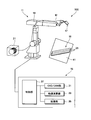
- FIG. 1 is a schematic diagram of a production system for producing a shaped article of the present invention.
- the manufacturing system 100 of the present configuration includes a layered manufacturing apparatus 11 and a controller 15 that generally controls the layered manufacturing apparatus 11.
- the layered shaping apparatus 11 has a welding robot 19 having a torch 17 at its tip end axis, and a filler material supply unit 23 for supplying a filler material (welding wire) M to the torch 17.
- the controller 15 has a CAD / CAM unit 31, a trajectory calculation unit 33, a storage unit 35, and a control unit 37 to which these are connected.
- the welding robot 19 is an articulated robot, and the welding material M is supported so as to be continuously supplied to the torch 17 provided on the tip end shaft.
- the position and posture of the torch 17 can be arbitrarily set three-dimensionally in the range of the degree of freedom of the robot arm.
- the torch 17 has a shield nozzle (not shown), and shield gas is supplied from the shield nozzle.
- the arc welding method used in this configuration may be any of consumable electrode methods such as coated arc welding and carbon dioxide gas arc welding, and non-consumable electrode methods such as TIG welding and plasma arc welding. It will be selected accordingly.
- the contact tip is disposed inside the shield nozzle, and the filler material M to which the melting current is supplied is held by the contact tip.
- the torch 17 generates an arc from the tip of the filler material M in a shield gas atmosphere while holding the filler material M.
- the filler material M is fed from the filler material supply unit 23 to the torch 17 by a feeding mechanism (not shown) attached to a robot arm or the like. Then, while the torch 17 is moved, when the filler material M continuously fed is melted and solidified, a linear welding bead 25 which is a molten solid of the filler material M is formed on the base plate 41.
- the heat source for melting the filler material M is not limited to the above-described arc.
- heat sources using other methods such as a heating method using an arc and a laser in combination, a heating method using a plasma, a heating method using an electron beam or a laser, etc. may be adopted.
- the amount of heating can be controlled more finely, and the state of the weld bead can be maintained more properly, which can contribute to further quality improvement of the laminated structure.
- the CAD / CAM unit 31 After creating the shape data of the three-dimensional object W to be produced, the CAD / CAM unit 31 divides it into a plurality of layers and generates layer shape data representing the shapes of the respective layers.
- the trajectory calculation unit 33 obtains a movement trajectory of the torch 17 based on the generated layer shape data.
- the storage unit 35 stores data such as the generated layer shape data and the movement trajectory of the torch 17.
- the control unit 37 executes a drive program based on the layer shape data stored in the storage unit 35 and the movement trajectory of the torch 17 to drive the welding robot 19.
- the control unit 37 executes a drive program based on the layer shape data stored in the storage unit 35 and the movement trajectory of the torch 17 to drive the welding robot 19. That is, the welding robot 19 moves the torch 17 while melting the filler material M with an arc based on the movement trajectory of the torch 17 generated by the trajectory calculation unit 33 according to a command from the controller 15.
- a plurality of welding beads 25 are formed obliquely on a base plate 41 made of a steel plate inclined with respect to the vertical plane and arranged to form a three-dimensional object W.
- the manufacturing system 100 configured as described above melts and melts the filler material M while moving the torch 17 by the driving of the welding robot 19 along the movement trajectory of the torch 17 generated from the set layer shape data.
- the filler material M is supplied onto the base plate 41.
- a plurality of linear welding beads 25 are formed obliquely on the base plate 41 inclined with respect to the vertical plane, and the three-dimensional object is stacked. W is shaped.
- the welding bead 25 is formed by moving the torch 17 obliquely to the vertical direction on the base plate 41 inclined with respect to the vertical surface.
- the influence of the gravity increases as the angle (base surface inclination angle) ⁇ between the base surface which is the surface of the base plate 41 and the vertical direction decreases, and the direction of the orbit of the torch 17 on the base plate 41 and the vertical direction.
- the larger the formed angle (orbital inclination angle) ⁇ the larger.
- the shaped object W is shaped while suppressing sagging and humping in the welding bead 25 as follows.
- the welding bead 25 is moved in the track direction inclined at the track inclination angle ⁇ with respect to the vertical direction.
- the case where it forms, and models the three-dimensional object W by which the layer of the welding bead 25 was laminated by two layers is demonstrated.
- the three-dimensional object W in this case has a bead formation site where the influence of gravity becomes maximum.
- the welding bead 25 formed at this portion is formed by the support bead 25A.
- the support bead 25A is a low heat input bead with a reduced amount of heat for melting the filler material. Since this support bead 25A is a low heat input bead, the viscosity in the molten state at the time of bead formation is made higher than that of the other weld beads 25 to be laminated thereafter, and the influence of gravity is not good. That is, even when the support bead 25A is formed at a portion where the influence of gravity becomes maximum, the occurrence of the sag due to the gravity is suppressed.
- a process window which is a setting range in which the moving speed V of the torch 17 and the current value I for arc generation are created in advance and stored in the storage unit 35 Determine from PW.
- FIG. 4 show the moving speed V of the torch 17 and the process window of the current value I for generation of an arc when the base plane inclination angle ⁇ is 0 ° with the base plate 41 being a vertical plane. It shows PW.
- the process window PW of the moving velocity V and the current value I becomes a range which becomes gradually narrower because the influence of gravity becomes larger as the track inclination angle ⁇ becomes larger. ing. Then, the control unit 37 determines the moving velocity V and the current value I for forming the support bead 25A from the process window PW stored in the storage unit 35.
- the control unit 37 drives the welding robot 19 after determination of the moving velocity V and the current value I, and gravity influence is generated along the generated movement locus.
- a support bead 25A is formed at the lower end portion which is the largest, at the determined moving speed V and current value I.
- the support bead 25A which is this low heat input bead, has a high viscosity at the time of bead formation, and can not be affected by weight. Therefore, the support bead 25A made of the low heat input bead is formed on the base plate 41 without sagging due to the influence of gravity, even if the portion to be formed is the portion where the influence of weight is the largest.
- the other welding beads 25 in the first layer are sequentially formed on the surface of the base plate 41 above the support beads 25A already formed.
- welding is performed on a portion of the surface of the base plate 41 adjacent to the upper side of the support bead 25A already formed.
- the bead 25 is formed.
- the weld bead 25 formed adjacent to the already formed support bead 25A is supported by the already formed support bead 25A.
- the welding bead 25 is formed by being supported by the support bead 25A, even if it is a high heat input bead which may sag due to the influence of gravity because the viscosity at the time of bead formation is low. As a result, sagging when forming the welding bead 25 is suppressed. Furthermore, as shown to (a) and (b) of FIG. 5C, the other welding bead 25 adjacent to the upper direction of the formed welding bead 25 is formed in order. At this time, since the welding bead 25 to be formed is supported by the welding bead 25 formed on the lower side, the sag at the time of forming the welding bead 25 is suppressed.
- the welding bead 25 formed in this portion is formed by the support bead 25A having a viscosity at bead formation higher than that of the other welding beads 25 to be laminated thereafter.
- the control unit 37 drives the welding robot 19 after determining the moving speed V and the current value I for forming the support bead 25A, and generates the generated movement.
- the support bead 25A is formed at the lower end portion where the gravity influence is maximum, at the determined moving speed V and current value I.
- the other welding beads 25 in the second layer are sequentially formed on the upper side of the support beads 25A already formed on the surface of the base plate 41. Also at this time, as shown in (a) and (b) of FIG. 6B, if weld bead 25 is formed on the surface of base plate 41 adjacent to the upper side of support bead 25A already formed, weld bead 25 , Are supported by the already formed support beads 25A. Therefore, the welding bead 25 is formed by being supported by the support bead 25A, even if it is a high heat input bead which may sag due to the influence of gravity because the viscosity at the time of bead formation is low.
- another welding bead 25 is formed by overlapping on the support bead 25A formed in the portion where the gravity effect is maximum.
- the support bead 25A is formed at the lower end portion of each bead layer.
- the other welding bead 25 can be formed by supporting the formed support bead 25A.
- the low heat input bead formed by reducing the amount of heat for melting the filler material M has a viscosity at the time of bead formation higher than that of the other welding beads 25 to be laminated thereafter, and can be affected by weight. Therefore, even if the portion to be formed is a portion where the weight effect is the largest, the support bead 25A made of the low heat input bead can be formed while suppressing the sag due to the gravity effect.
- the influence of gravity is maximum from the base surface inclination angle ⁇ with respect to the vertical surface of the base surface consisting of the surface of the base plate 41 and the upper surface of the lower layer welding bead and the track inclination angle ⁇ with respect to the vertical direction
- the molded portion can be manufactured by obtaining the portion where the support bead 25 is formed, and forming the support bead 25A accurately in the portion.
- the object W can be formed smoothly with respect to the base surface with the base surface inclination angle ⁇ and the orbit inclination angle ⁇ .
- FIG. 7 is a view showing an example of manufacturing a shaped article.
- the object W is formed on a base 52 placed on a base 51.
- the base 52 is formed in a trapezoidal shape in cross section, and is inclined so that the side faces upward.
- the welding bead 25 is formed on a base surface 53 formed of inclined side surfaces of the base material 52.
- a plurality of bead layers 54 a, 54 b, 54 c, 54 d,... Formed of welding beads 25 are formed on the base surface 53 so as to overlap in the lateral direction S.
- a plurality of bead layers 54a, 54b, 54c, 54d, ... are stacked in the horizontal direction from the base surface 53.
- the lower end portion where the gravity effect is maximum with respect to the base surface 53 is the track inclination angle ⁇ ( ⁇ ( ⁇ ) along the base surface 53 with the support bead 25A1.
- ⁇ ( ⁇ ) the track inclination angle
- the other welding beads 25 are sequentially formed along the base surface 53 on the upper side of the support bead 25A1 so as to be locked to the support bead 25A1.
- the bead layer 54 a of the first layer is formed on the base surface 53.
- the lower end portion where the influence of gravity on the first bead layer 54a formed on the base surface 53 is maximized along the base surface 53 by the support bead 25A2 Bonding to the bead layer 54a) in the direction of the track inclination angle ⁇ ( ⁇ ⁇ 0 °).
- another welding bead 25 is sequentially formed along the base surface 53 (joined to the first bead layer 54a) above the supporting bead 25A2 so as to be locked to the supporting bead 25A2.
- lower end portions of the bead layers 54a, 54b, 54c, 54d,... Where the influence of gravity becomes maximum are formed by the support beads 25A1, 25A2,.
- ⁇ ⁇ ⁇ By forming another welding bead 25 along the base surface 53 so as to be locked, even if the welding bead 25 is laminated in a diagonal direction (track inclination angle ⁇ direction) in which it tends to sag, the support beads 25A1 and 25A2 , ... supported by. This can prevent bead drooping and humping.
- the bead layers 54a, 54b, 54c, 54d,... are stably formed by the formation of the support beads 25A1, 25A2, ..., the side surfaces of the base material 52 having the inclined base surface 53 are provided.
- the bead layer 54 of the welding bead 25 can be superimposed on the side S. That is, according to the manufacturing method of the present embodiment, when the side surface of the base material 52 placed on the base 51 has the inclined base surface 53, the support beads 25A1, 25A2,.
- the bead layers 54a, 54b, 54c, 54d,... Formed of the other welding beads 25 are suitable to be formed to overlap in the lateral direction S.
- the present invention is not limited to this, and the torch 17 may be movable relative to the base plate 41.
- the trajectory of the torch 17 means the trajectory of the relative movement of the torch 17 and the base plate 41.
- a method for producing a shaped article comprising melting and solidifying a filler material to form a weld bead on a base surface along a path of a torch, and forming a shaped article by the weld bead,
- the three-dimensional object has a bead forming portion where the influence of gravity is maximized, and at the bead forming portion, a support bead having a higher viscosity at the time of formation of the weld bead than that of other weld beads is formed.
- the manufacturing method of the molded article which forms the said other welding bead.
- another welding bead is formed by overlapping on the support bead formed at the portion where the gravity effect is the largest.
- another welding bead can be formed by using the formed support bead as a support. Therefore, it is possible to suppress the other welding beads from drooping under the influence of gravity, and to suppress the occurrence of humping which may be caused by increasing the moving speed of the torch in order to suppress the sagging. Thereby, high-quality shaped articles can be manufactured while suppressing the tact time.
- the manufacturing method of the shaped article according to (1) or (2), wherein the bead formation site is determined by using the following as an index of the influence of gravity. According to the method of manufacturing this shaped object, a portion where the gravity influence is maximum is determined from the base surface inclination angle with respect to the vertical surface of the base surface and the track inclination angle with respect to the vertical direction of the torch trajectory on the base surface.
- the support bead can be precisely formed to produce a shaped article.
- the shaped article is formed by laminating a bead layer including a plurality of the welding beads formed on the base surface, When the said base surface inclines from a perpendicular direction, the manufacturing method of the shaped article as described in (3) or (4) which forms the said support bead in the lower end part of the said bead layer, respectively.
- a three-dimensional object formed of a plurality of weld beads is obtained. It can be manufactured without dripping or humping.
- the support bead and the other weld bead in the bead layer are formed in the direction inclined from the vertical direction by the track inclination angle (5)
- the manufacturing method of the shaped article as described in is formed by a support bead, and the other weld bead is formed along the base surface so as to be locked to the support bead, thereby laminating the weld bead in an oblique direction Even by supporting by the support bead, it is possible to prevent bead drooping and humping.
- the base surface is provided on the side surface of the substrate placed on the stage, and the bead layer having the support bead and the other welding bead on the side surface is directed to the side of the substrate (6)
- the manufacturing method of the molded article as described in (6) Since each layer is stably formed by the formation of the support bead, it is possible to overlap the layer of the weld bead laterally with respect to the side surface of the base having the inclined base surface.
- the manufacturing apparatus of the molded article provided with.
- a support bead having a viscosity higher than that of the other welding beads is formed at the time of bead formation, at a portion where the influence of gravity is the largest.
- another welding bead can be formed by using the formed support bead as a support. Therefore, it is possible to suppress the other welding beads from drooping under the influence of gravity, and to suppress the occurrence of humping which may be caused by increasing the moving speed of the torch in order to suppress the sagging. Thereby, high-quality shaped articles can be manufactured while suppressing the tact time.
- a shaped object in which a plurality of welding beads obtained by melting and solidifying a filler material are laminated The three-dimensional object has a bead forming portion where the influence of gravity is maximized, and at the bead forming portion, a support bead having a viscosity higher than that of the other weld beads at the time of forming the weld bead is formed. Shaped object on which the other welding bead is formed. According to this shaped object, the portion where the gravity effect is the largest is formed by the support bead, and another weld bead is formed on the support bead.
- the support bead acts as a support for the other weld bead, suppresses the other weld bead from dropping under the influence of gravity, and accelerates the moving speed of the torch for forming the weld bead to suppress the drop. It can be shaped without any defect that causes humping. Thereby, it can manufacture in high quality, suppressing the tact time concerning manufacture.
Landscapes
- Engineering & Computer Science (AREA)
- Physics & Mathematics (AREA)
- Plasma & Fusion (AREA)
- Mechanical Engineering (AREA)
- Chemical & Material Sciences (AREA)
- Manufacturing & Machinery (AREA)
- Materials Engineering (AREA)
- Optics & Photonics (AREA)
- Butt Welding And Welding Of Specific Article (AREA)
- Moulding By Coating Moulds (AREA)
Abstract
垂れやハンピングなどの不具合なく溶着ビードを効率よく形成して造形物を造形することが可能な造形物の製造方法、製造装置及び造形物を提供する。この造形物の製造方法では、溶加材を溶融及び凝固させてトーチの軌道に沿った基面上に溶着ビードを形成し、この溶着ビードにより造形物を形成する。その際、造形物は重力影響が最大となるビード形成部位を有し、そのビード形成部位に、溶着ビードの形成時の粘度が他の溶着ビードよりも高い支持ビードを形成する。そして、支持ビードに重ねて他の溶着ビードを形成する。
Description
本発明は、造形物の製造方法、製造装置及び造形物に関する。
近年、生産手段としての3Dプリンタのニーズが高まっており、特に金属材料への適用については航空機業界等で実用化に向けて研究開発が行われている。例えば、金属材料を用いた3Dプリンタは、レーザやアーク等の熱源を用いて、金属粉体や金属ワイヤを溶融させ、溶融金属を積層させて造形物を造形する。
このような造形物を造形する技術として、トーチ走査工程において、水平面または傾斜面に沿ってトーチを走査させて肉盛りを進行させて三次元形状物を製造する技術が知られている(例えば、特許文献1参照)。
ところで、溶着ビードを基板や下層の溶着ビードの基面に形成する場合、その基面が傾斜していると、重力の影響による垂れが生じるおそれがある。また、溶着ビードが垂れないように溶接トーチの移動速度を速めると、溶着ビードが途切れるハンピングが生じるおそれがある。このため、溶着ビードを形成する基面の状態に影響されることなく、垂れやハンピングなどの不具合なく円滑に溶着ビードを形成して造形物を製造する技術が要求されている。
本発明の目的は、垂れやハンピングなどの不具合なく溶着ビードを効率よく形成して造形物を造形することが可能な造形物の製造方法、製造装置及び造形物を提供することにある。
本発明は下記の構成からなる。
(1) 溶加材を溶融及び凝固させてトーチの軌道に沿った基面上に溶着ビードを形成し、前記溶着ビードにより造形物を形成する造形物の製造方法であって、
前記造形物は重力影響が最大となるビード形成部位を有し、該ビード形成部位に、前記溶着ビードの形成時の粘度が他の溶着ビードよりも高い支持ビードを形成し、前記支持ビードに重ねて前記他の溶着ビードを形成する
造形物の製造方法。
(2) 溶加材を溶融及び凝固させた溶着ビードにより、基面上に造形物を形成する造形物の製造装置であって、
前記溶着ビードを形成するトーチと、
前記トーチを前記基面に対して相対移動させる移動機構と、
前記造形物は重力影響が最大となるビード形成部位を有し、該ビード形成部位に、前記溶着ビードの形成時の粘度が他の溶着ビードよりも高い支持ビードを形成し、前記支持ビードに重ねて前記他の溶着ビードを形成するように前記移動機構及び前記トーチを制御する制御部と、
を備える造形物の製造装置。
(3) 溶加材を溶融及び凝固させた複数の溶着ビードが積層された造形物であって、
前記造形物は重力影響が最大となるビード形成部位を有し、該ビード形成部位に、前記溶着ビードの形成時の粘度が他の溶着ビードよりも高い支持ビードが形成され、前記支持ビードに重ねて前記他の溶着ビードが形成されている造形物。
(1) 溶加材を溶融及び凝固させてトーチの軌道に沿った基面上に溶着ビードを形成し、前記溶着ビードにより造形物を形成する造形物の製造方法であって、
前記造形物は重力影響が最大となるビード形成部位を有し、該ビード形成部位に、前記溶着ビードの形成時の粘度が他の溶着ビードよりも高い支持ビードを形成し、前記支持ビードに重ねて前記他の溶着ビードを形成する
造形物の製造方法。
(2) 溶加材を溶融及び凝固させた溶着ビードにより、基面上に造形物を形成する造形物の製造装置であって、
前記溶着ビードを形成するトーチと、
前記トーチを前記基面に対して相対移動させる移動機構と、
前記造形物は重力影響が最大となるビード形成部位を有し、該ビード形成部位に、前記溶着ビードの形成時の粘度が他の溶着ビードよりも高い支持ビードを形成し、前記支持ビードに重ねて前記他の溶着ビードを形成するように前記移動機構及び前記トーチを制御する制御部と、
を備える造形物の製造装置。
(3) 溶加材を溶融及び凝固させた複数の溶着ビードが積層された造形物であって、
前記造形物は重力影響が最大となるビード形成部位を有し、該ビード形成部位に、前記溶着ビードの形成時の粘度が他の溶着ビードよりも高い支持ビードが形成され、前記支持ビードに重ねて前記他の溶着ビードが形成されている造形物。
本発明によれば、垂れやハンピングなどの不具合なく溶着ビードを効率よく形成して造形物を造形することができる。
以下、本発明の実施形態について、図面を参照して詳細に説明する。
図1は本発明の造形物を製造する製造システムの模式的な概略構成図である。
本構成の製造システム100は、積層造形装置11と、積層造形装置11を統括制御するコントローラ15と、を備える。
図1は本発明の造形物を製造する製造システムの模式的な概略構成図である。
本構成の製造システム100は、積層造形装置11と、積層造形装置11を統括制御するコントローラ15と、を備える。
積層造形装置11は、先端軸にトーチ17を有する溶接ロボット19と、トーチ17に溶加材(溶接ワイヤ)Mを供給する溶加材供給部23とを有する。
コントローラ15は、CAD/CAM部31と、軌道演算部33と、記憶部35と、これらが接続される制御部37と、を有する。
溶接ロボット19は、多関節ロボットであり、先端軸に設けたトーチ17には、溶加材Mが連続供給可能に支持される。トーチ17の位置や姿勢は、ロボットアームの自由度の範囲で3次元的に任意に設定可能となっている。
トーチ17は、不図示のシールドノズルを有し、シールドノズルからシールドガスが供給される。本構成で用いられるアーク溶接法としては、被覆アーク溶接や炭酸ガスアーク溶接等の消耗電極式、TIG溶接やプラズマアーク溶接等の非消耗電極式のいずれであってもよく、作製する造形物Wに応じて適宜選定される。
例えば、消耗電極式の場合、シールドノズルの内部にはコンタクトチップが配置され、溶融電流が給電される溶加材Mがコンタクトチップに保持される。トーチ17は、溶加材Mを保持しつつ、シールドガス雰囲気で溶加材Mの先端からアークを発生する。溶加材Mは、ロボットアーム等に取り付けた不図示の繰り出し機構により、溶加材供給部23からトーチ17に送給される。そして、トーチ17を移動しつつ、連続送給される溶加材Mを溶融及び凝固させると、ベースプレート41上に溶加材Mの溶融凝固体である線状の溶着ビード25が形成される。
溶加材Mを溶融させる熱源としては、上記したアークに限らない。例えば、アークとレーザとを併用した加熱方式、プラズマを用いる加熱方式、電子ビームやレーザを用いる加熱方式等、他の方式による熱源を採用してもよい。電子ビームやレーザにより加熱する場合、加熱量を更に細かく制御でき、溶着ビードの状態をより適正に維持して、積層構造物の更なる品質向上に寄与できる。
CAD/CAM部31は、作製しようとする造形物Wの形状データを作成した後、複数の層に分割して各層の形状を表す層形状データを生成する。軌道演算部33は、生成された層形状データに基づいてトーチ17の移動軌跡を求める。記憶部35は、生成された層形状データやトーチ17の移動軌跡等のデータを記憶する。
制御部37は、記憶部35に記憶された層形状データやトーチ17の移動軌跡に基づく駆動プログラムを実行して、溶接ロボット19を駆動する。
制御部37は、記憶部35に記憶された層形状データやトーチ17の移動軌跡に基づく駆動プログラムを実行して、溶接ロボット19を駆動する。つまり、溶接ロボット19は、コントローラ15からの指令により、軌道演算部33で生成したトーチ17の移動軌跡に基づき、溶加材Mをアークで溶融させながらトーチ17を移動する。図1においては、鉛直面に対して傾斜した鋼板からなるベースプレート41上に複数の溶着ビード25を斜めに形成して並べて造形物Wを造形する様子を示している。
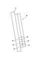
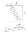
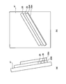
上記構成の製造システム100は、設定された層形状データから生成されるトーチ17の移動軌跡に沿って、トーチ17を溶接ロボット19の駆動により移動させながら、溶加材Mを溶融させ、溶融した溶加材Mをベースプレート41上に供給する。これにより、例えば、図2A及び図2Bに示すように、鉛直面に対して傾斜したベースプレート41に複数の線状の溶着ビード25が斜めに形成されて並べられて複数層に積層された造形物Wが造形される。
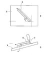
ところで、図3の(a)及び(b)に示すように、鉛直面に対して傾斜したベースプレート41に、鉛直方向に対して斜めにトーチ17を移動させて溶着ビード25を形成する場合、形成する溶着ビード25に、重力の影響による垂れが生じるおそれがある。この重力の影響は、ベースプレート41の表面である基面と鉛直方向との成す角(基面傾斜角)θが小さいほど大きくなり、また、ベースプレート41上におけるトーチ17の軌道方向と鉛直方向との成す角(軌道傾斜角)φが大きいほど大きくなる。このように、形成する溶着ビード25が重力の影響を大きく受ける場合、トーチ17の移動速度Vを速めることで垂れを抑制できるが、溶着ビード25が途切れるハンピングが生じるおそれがある。
このため、本実施形態では、以下のように、溶着ビード25における垂れ及びハンピングを抑制しつつ造形物Wを造形する。なお、ここでは、ベースプレート41が鉛直面に対して傾いて基面傾斜角θが90°未満とされたベースプレート41に、鉛直方向に対して軌道傾斜角φで傾斜した軌道方向へ溶着ビード25を形成し、溶着ビード25の層が二層積層された造形物Wを造形する場合について説明する。この場合の造形物Wは、重力影響が最大となるビード形成部位を有する。
(一層目)
複数の溶着ビード25を形成して造形物Wの一層目を造形する場合、まず、複数の溶着ビード25の形成部位における重力影響が最大となる部位を求める。この重力影響が最大となる部位を求めるにあたっては、溶着ビード25を形成するベースプレート41の鉛直面に対する基面傾斜角θ及びベースプレート41上における溶着ビード25を形成するトーチ17の軌道方向の鉛直方向に対する軌道傾斜角φを重力影響の指標として、例えば、cosθsinφから求める。
複数の溶着ビード25を形成して造形物Wの一層目を造形する場合、まず、複数の溶着ビード25の形成部位における重力影響が最大となる部位を求める。この重力影響が最大となる部位を求めるにあたっては、溶着ビード25を形成するベースプレート41の鉛直面に対する基面傾斜角θ及びベースプレート41上における溶着ビード25を形成するトーチ17の軌道方向の鉛直方向に対する軌道傾斜角φを重力影響の指標として、例えば、cosθsinφから求める。
基面傾斜角θで傾斜しているベースプレート41に、鉛直方向に対して軌道傾斜角φで傾斜した軌道方向へ溶着ビード25を形成して造形物Wを造形する場合、一層目では、下端部位が、重力影響が最大となる部位となる。
溶着ビード25の形成部位における重力影響が最大となる部位を求めたら、この部位に形成する溶着ビード25を、支持ビード25Aで形成する。この支持ビード25Aは、溶加材を溶融させるための熱量を下げた低入熱ビードである。この支持ビード25Aは、低入熱ビードであることから、その後に積層させる他の溶着ビード25よりもビード形成時における溶融状態の粘度が高くされて、重力影響が受け辛くされている。つまり、この支持ビード25Aは、重力影響が最大となる部位に形成しても、重力による垂れの発生が抑制される。
この支持ビード25Aを形成するにあたり、例えば、本例では、トーチ17の移動速度V及びアークの発生のための電流値Iを、予め作成して記憶部35に記憶させた設定範囲であるプロセスウインドウPWから決定する。
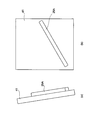
図4の(a)及び(b)は、ベースプレート41が鉛直面とされた基面傾斜角θが0°のときのトーチ17の移動速度V及びアークの発生のための電流値IのプロセスウインドウPWを示している。図4の(a)及び(b)に示すように、移動速度V及び電流値IのプロセスウインドウPWは、軌道傾斜角φが大きくなるにしたがって重力の影響が大きくなるため次第に狭くなる範囲となっている。そして、制御部37は、支持ビード25Aを形成するための移動速度V及び電流値Iを、記憶部35に記憶されたプロセスウインドウPWから決定する。
制御部37は、図5Aの(a)及び(b)に示すように、移動速度V及び電流値Iの決定後、溶接ロボット19を駆動させ、生成された移動軌跡に沿って、重力影響が最大となる下端部位に、決定した移動速度V及び電流値Iで支持ビード25Aを形成する。この低入熱ビードである支持ビード25Aは、ビード形成時の粘度が高く、重量影響を受け辛くできる。したがって、低入熱ビードからなる支持ビード25Aは、形成する部位が重量影響が最大となる部位であっても、重力影響による垂れが生じることなくベースプレート41に形成される。
その後、一層目における他の溶着ビード25を、ベースプレート41の表面における既に形成した支持ビード25Aの上方側に順に形成する。これらの他の溶着ビード25を形成するには、まず、図5Bの(a)及び(b)に示すように、ベースプレート41の表面における既に形成した支持ビード25Aの上方側に隣接する部位に溶着ビード25を形成する。すると、既に形成されている支持ビード25Aに隣接して形成する溶着ビード25は、既に形成されている支持ビード25Aに支えられる。したがって、この溶着ビード25は、ビード形成時の粘度が低いために重力影響によって垂れが生じ得る高入熱ビードであっても、支持ビード25Aによって支えられて形成される。これにより、この溶着ビード25を形成する際の垂れが抑制される。さらに、図5Cの(a)及び(b)に示すように、形成した溶着ビード25の上方に隣接する他の溶着ビード25を順に形成する。このとき、形成する溶着ビード25は、下方側に形成されている溶着ビード25によって支えられて形成されるので、この溶着ビード25を形成する際の垂れが抑制される。
(二層目)
一層目に積層させるように複数の溶着ビード25を形成して造形物Wの二層目を造形する場合、この二層目における重力影響が最大となる部位を求める。基面傾斜角θで傾斜しているベースプレート41に、鉛直方向に対して軌道傾斜角φで傾斜した軌道方向へ溶着ビード25を形成して造形物Wを造形することから、二層目においても、下端部位が、重力影響が最大となる部位となる。
一層目に積層させるように複数の溶着ビード25を形成して造形物Wの二層目を造形する場合、この二層目における重力影響が最大となる部位を求める。基面傾斜角θで傾斜しているベースプレート41に、鉛直方向に対して軌道傾斜角φで傾斜した軌道方向へ溶着ビード25を形成して造形物Wを造形することから、二層目においても、下端部位が、重力影響が最大となる部位となる。
重力影響が最大となる部位を求めたら、この部位に形成する溶着ビード25を、その後に積層させる他の溶着ビード25よりもビード形成時の粘度が高い支持ビード25Aで形成する。
制御部37は、図6Aの(a)及び(b)に示すように、支持ビード25Aを形成するための移動速度V及び電流値Iの決定後、溶接ロボット19を駆動させ、生成された移動軌跡に沿って、重力影響が最大となる下端部位に、決定した移動速度V及び電流値Iで支持ビード25Aを形成する。
その後、二層目における他の溶着ビード25を、ベースプレート41の表面における既に形成した支持ビード25Aの上方側に順に形成する。このときも、図6Bの(a)及び(b)に示すように、ベースプレート41の表面における既に形成した支持ビード25Aの上方側に隣接する部位に溶着ビード25を形成すると、この溶着ビード25は、既に形成されている支持ビード25Aに支えられる。したがって、この溶着ビード25は、ビード形成時の粘度が低いために重力影響によって垂れが生じ得る高入熱ビードであっても、支持ビード25Aによって支えられて形成される。これにより、この溶着ビード25を形成する際の垂れが抑制される。さらに、図6Cの(a)及び(b)に示すように、形成した溶着ビード25の上方に隣接する他の溶着ビード25を順に形成する。このとき、形成する溶着ビード25は、下方側に形成されている溶着ビード25によって支えられて形成されるので、この溶着ビード25を形成する際の垂れが抑制される。
以上、説明したように、本実施形態にかかる造形物の製造方法、製造装置及び造形物によれば、重力影響が最大となる部位に形成した支持ビード25Aに重ねて他の溶着ビード25を形成する。具体的には、溶着ビード25を形成するベースプレート41の表面や下層の溶着ビード25の上面からなる基面が傾斜している際に、各ビード層における下端部位に、支持ビード25Aを形成する。これにより、形成した支持ビード25Aを支えとして他の溶着ビード25を形成することができる。したがって、他の溶着ビード25が重力影響を受けて垂れるのを抑制でき、また、垂れを抑えるためにトーチ17の移動速度Vを速めることで生じるおそれがあるハンピングの発生を抑制できる。これにより、タクトタイムを抑えつつ高品質な造形物Wを製造できる。
また、溶加材Mを溶融させるための熱量を下げて形成した低入熱ビードは、その後に積層させる他の溶着ビード25よりもビード形成時の粘度が高く、重量影響を受け辛くできる。したがって、形成する部位が重量影響が最大となる部位であっても、低入熱ビードからなる支持ビード25Aを、重力影響による垂れを抑えつつ形成することができる。
また、ベースプレート41の表面や下層の溶着ビードの上面からなる基面の鉛直面に対する基面傾斜角θ及び基面上におけるトーチ17の軌道方向の鉛直方向に対する軌道傾斜角φから重力影響が最大となる部位を求め、その部位に支持ビード25Aを的確に形成して造形物を製造することができる。
特に、cosθsinφから重力影響の指標を求めるので、基面傾斜角がθ及び軌道傾斜角がφの基面に対して造形物Wを円滑に形成することができる。
次に、上記実施形態に係る製造方法による造形物の製造例について説明する。
図7は、造形物の製造例を示す図である。
図7に示すように、造形物Wは、土台51に載置した基材52に形成されている。基材52は、断面台形状に形成されており、その側面が上方へ向くように傾斜されている。溶着ビード25は、この基材52の傾斜した側面からなる基面53に形成されている。そして、基面53には、溶着ビード25からなる複数のビード層54a,54b,54c,54d,・・・が側方Sに向けて重なって形成されている。具体的には、基材52には、複数のビード層54a,54b,54c,54d,・・・が基面53から水平方向に積層されている。
図7は、造形物の製造例を示す図である。
図7に示すように、造形物Wは、土台51に載置した基材52に形成されている。基材52は、断面台形状に形成されており、その側面が上方へ向くように傾斜されている。溶着ビード25は、この基材52の傾斜した側面からなる基面53に形成されている。そして、基面53には、溶着ビード25からなる複数のビード層54a,54b,54c,54d,・・・が側方Sに向けて重なって形成されている。具体的には、基材52には、複数のビード層54a,54b,54c,54d,・・・が基面53から水平方向に積層されている。
基材52の基面53に造形物Wを形成するには、まず、基面53に対して重力影響が最大となる下端部位を支持ビード25A1で基面53に沿って軌道傾斜角φ(φ≠0°)方向に形成する。そして、この支持ビード25A1に係止させるように、支持ビード25A1の上方側に他の溶着ビード25を基面53に沿って順に形成する。これにより、基面53に一層目のビード層54aを形成する。
二層目以降のビード層54bを形成する場合、基面53に形成した一層目のビード層54aに対して重力影響が最大となる下端部位を支持ビード25A2で基面53に沿って(一層目のビード層54aに接合して)軌道傾斜角φ(φ≠0°)方向に形成する。そして、この支持ビード25A2に係止させるように、支持ビード25A2の上方側に他の溶着ビード25を基面53に沿って(一層目のビード層54aに接合して)順に形成する。
この製造例では、各ビード層54a,54b,54c,54d,・・・における重力影響が最大となる下端部位を支持ビード25A1,25A2,・・・で形成し、各支持ビード25A1,25A2,・・・に係止させるように他の溶着ビード25を基面53に沿って形成することで、溶着ビード25が垂れやすい斜め方向(軌道傾斜角φ方向)に積層しても支持ビード25A1,25A2,・・・によって支持される。これにより、ビード垂れやハンピングを防止できる。
特に、支持ビード25A1,25A2,・・・の形成により各ビード層54a,54b,54c,54d,・・・が安定して形成されるため、傾斜した基面53を有する基材52の側面に対して、側方Sへ溶着ビード25のビード層54を重ねることができる。すなわち、本実施形態に係る製造方法によれば、土台51に載置した基材52の側面が傾斜した基面53を有する場合に、側面からなる基面53に支持ビード25A1,25A2,・・・と他の溶着ビード25からなるビード層54a,54b,54c,54d,・・・を側方Sに重ねて形成するのに好適である。
本発明は上記の実施形態に限定されるものではなく、実施形態の各構成を相互に組み合わせることや、明細書の記載、並びに周知の技術に基づいて、当業者が変更、応用することも本発明の予定するところであり、保護を求める範囲に含まれる。
例えば、本構成の積層造形装置11は、移動機構として溶接ロボット19を用いているが、これに限らず、トーチ17をベースプレート41に対して相対移動できる構成であってもよい。その場合、トーチ17の軌道とは、トーチ17とベースプレート41との相対移動の軌道を意味する。
以上の通り、本明細書には次の事項が開示されている。
(1) 溶加材を溶融及び凝固させてトーチの軌道に沿った基面上に溶着ビードを形成し、前記溶着ビードにより造形物を形成する造形物の製造方法であって、
前記造形物は重力影響が最大となるビード形成部位を有し、該ビード形成部位に、前記溶着ビードの形成時の粘度が他の溶着ビードよりも高い支持ビードを形成し、前記支持ビードに重ねて前記他の溶着ビードを形成する
造形物の製造方法。
この造形物の製造方法によれば、重力影響が最大となる部位に形成した支持ビードに重ねて他の溶着ビードを形成する。これにより、形成した支持ビードを支えとして他の溶着ビードを形成することができる。したがって、他の溶着ビードが重力影響を受けて垂れるのを抑制でき、また、垂れを抑えるためにトーチの移動速度を速めることで生じるおそれがあるハンピングの発生を抑制できる。これにより、タクトタイムを抑えつつ高品質な造形物を製造できる。
(1) 溶加材を溶融及び凝固させてトーチの軌道に沿った基面上に溶着ビードを形成し、前記溶着ビードにより造形物を形成する造形物の製造方法であって、
前記造形物は重力影響が最大となるビード形成部位を有し、該ビード形成部位に、前記溶着ビードの形成時の粘度が他の溶着ビードよりも高い支持ビードを形成し、前記支持ビードに重ねて前記他の溶着ビードを形成する
造形物の製造方法。
この造形物の製造方法によれば、重力影響が最大となる部位に形成した支持ビードに重ねて他の溶着ビードを形成する。これにより、形成した支持ビードを支えとして他の溶着ビードを形成することができる。したがって、他の溶着ビードが重力影響を受けて垂れるのを抑制でき、また、垂れを抑えるためにトーチの移動速度を速めることで生じるおそれがあるハンピングの発生を抑制できる。これにより、タクトタイムを抑えつつ高品質な造形物を製造できる。
(2) 前記支持ビードを、前記他の溶着ビードよりも前記溶加材への入熱量を低下させて形成する(1)に記載の造形物の製造方法。
この造形物の製造方法によれば、支持ビードではビード形成時の粘度が高くされて重力影響が受け辛くされる。よって、重力影響が最大となる部位に他の溶着ビードを形成しても、重力による垂れの発生が抑制される。
この造形物の製造方法によれば、支持ビードではビード形成時の粘度が高くされて重力影響が受け辛くされる。よって、重力影響が最大となる部位に他の溶着ビードを形成しても、重力による垂れの発生が抑制される。
(3) 前記溶着ビードを形成する前記基面が鉛直方向と成す基面傾斜角と、前記基面上で前記溶着ビードを形成する際の前記トーチの軌道方向が鉛直方向と成す軌道傾斜角とを前記重力影響の指標にして、前記ビード形成部位を決定する(1)又は(2)に記載の造形物の製造方法。
この造形物の製造方法によれば、基面の鉛直面に対する基面傾斜角及び基面上におけるトーチの軌道方向の鉛直方向に対する軌道傾斜角から重力影響が最大となる部位を求め、その部位に支持ビードを的確に形成して造形物を製造することができる。
この造形物の製造方法によれば、基面の鉛直面に対する基面傾斜角及び基面上におけるトーチの軌道方向の鉛直方向に対する軌道傾斜角から重力影響が最大となる部位を求め、その部位に支持ビードを的確に形成して造形物を製造することができる。
(4) 前記基面傾斜角をθ、前記軌道傾斜角をφとしたときに、前記重力影響の指標をcosθsinφから求める(3)に記載の造形物の製造方法。
この造形物の製造方法によれば、cosθsinφから重力影響の指標を求めるので、基面傾斜角がθ及び軌道傾斜角がφの基面に対して造形物を円滑に形成することができる。
この造形物の製造方法によれば、cosθsinφから重力影響の指標を求めるので、基面傾斜角がθ及び軌道傾斜角がφの基面に対して造形物を円滑に形成することができる。
(5) 前記造形物は、前記基面上に形成された複数の前記溶着ビードを含むビード層が積層されており、
前記基面が鉛直方向から傾斜している場合に、前記ビード層の下端部位に前記支持ビードをそれぞれ形成する(3)又は(4)に記載の造形物の製造方法。
各層における重力影響が最大となる下端部位を支持ビードで形成し、この支持ビードに係止させるように他の溶着ビードを基面に沿って形成することで、複数の溶着ビードからなる造形物を、垂れやハンピングなく製造することができる。
前記基面が鉛直方向から傾斜している場合に、前記ビード層の下端部位に前記支持ビードをそれぞれ形成する(3)又は(4)に記載の造形物の製造方法。
各層における重力影響が最大となる下端部位を支持ビードで形成し、この支持ビードに係止させるように他の溶着ビードを基面に沿って形成することで、複数の溶着ビードからなる造形物を、垂れやハンピングなく製造することができる。
(6) 前記基面が鉛直方向から傾斜している場合に、前記ビード層内における前記支持ビードと前記他の溶着ビードを、鉛直方向から前記軌道傾斜角で傾斜した方向に形成する(5)に記載の造形物の製造方法。
各層における重力影響が最大となる下端部位を支持ビードで形成し、この支持ビードに係止させるように他の溶着ビードを基面に沿って形成することで、溶着ビードが垂れやすい斜め方向に積層しても支持ビードによって支持されることでビード垂れやハンピングを防止することができる。
各層における重力影響が最大となる下端部位を支持ビードで形成し、この支持ビードに係止させるように他の溶着ビードを基面に沿って形成することで、溶着ビードが垂れやすい斜め方向に積層しても支持ビードによって支持されることでビード垂れやハンピングを防止することができる。
(7) 前記基面は、ステージに載置した基材の側面に設けられ、前記側面に、前記支持ビードと前記他の溶着ビードとを有する前記ビード層を、前記基材の側方に向けて積層する(6)に記載の造形物の製造方法。
支持ビードの形成により各層が安定して形成されるため、傾斜した基面を有する基材の側面に対して、側方へ溶着ビードの層を重ねることができる。
支持ビードの形成により各層が安定して形成されるため、傾斜した基面を有する基材の側面に対して、側方へ溶着ビードの層を重ねることができる。
(8) 溶加材を溶融及び凝固させた溶着ビードにより、基面上に造形物を形成する造形物の製造装置であって、
前記溶着ビードを形成するトーチと、
前記トーチを前記基面に対して相対移動させる移動機構と、
前記造形物は重力影響が最大となるビード形成部位を有し、該ビード形成部位に、前記溶着ビードの形成時の粘度が他の溶着ビードよりも高い支持ビードを形成し、前記支持ビードに重ねて前記他の溶着ビードを形成するように前記移動機構及び前記トーチを制御する制御部と、
を備える造形物の製造装置。
この造形物の製造装置によれば、重力影響が最大となる部位に、ビード形成時に他の溶着ビードよりも高い粘度となる支持ビードを形成する。これにより、形成した支持ビードを支えとして他の溶着ビードを形成することができる。したがって、他の溶着ビードが重力影響を受けて垂れるのを抑制でき、また、垂れを抑えるためにトーチの移動速度を速めることで生じるおそれがあるハンピングの発生を抑制できる。これにより、タクトタイムを抑えつつ高品質な造形物を製造できる。
前記溶着ビードを形成するトーチと、
前記トーチを前記基面に対して相対移動させる移動機構と、
前記造形物は重力影響が最大となるビード形成部位を有し、該ビード形成部位に、前記溶着ビードの形成時の粘度が他の溶着ビードよりも高い支持ビードを形成し、前記支持ビードに重ねて前記他の溶着ビードを形成するように前記移動機構及び前記トーチを制御する制御部と、
を備える造形物の製造装置。
この造形物の製造装置によれば、重力影響が最大となる部位に、ビード形成時に他の溶着ビードよりも高い粘度となる支持ビードを形成する。これにより、形成した支持ビードを支えとして他の溶着ビードを形成することができる。したがって、他の溶着ビードが重力影響を受けて垂れるのを抑制でき、また、垂れを抑えるためにトーチの移動速度を速めることで生じるおそれがあるハンピングの発生を抑制できる。これにより、タクトタイムを抑えつつ高品質な造形物を製造できる。
(9) 溶加材を溶融及び凝固させた複数の溶着ビードが積層された造形物であって、
前記造形物は重力影響が最大となるビード形成部位を有し、該ビード形成部位に、前記溶着ビードの形成時の粘度が他の溶着ビードよりも高い支持ビードが形成され、前記支持ビードに重ねて前記他の溶着ビードが形成されている造形物。
この造形物によれば、重力影響が最大となる部位が支持ビードで形成され、この支持ビードに重ねて他の溶着ビードが形成されている。したがって、支持ビードが他の溶着ビードの支えとなり、他の溶着ビードが重力影響を受けて垂れるのを抑制し、しかも、垂れを抑えるために溶着ビードを形成するためのトーチの移動速度を速めてハンピングを生じさせるような不具合なく造形することができる。これにより、製造にかかるタクトタイムを抑えつつ高品質に製造できる。
前記造形物は重力影響が最大となるビード形成部位を有し、該ビード形成部位に、前記溶着ビードの形成時の粘度が他の溶着ビードよりも高い支持ビードが形成され、前記支持ビードに重ねて前記他の溶着ビードが形成されている造形物。
この造形物によれば、重力影響が最大となる部位が支持ビードで形成され、この支持ビードに重ねて他の溶着ビードが形成されている。したがって、支持ビードが他の溶着ビードの支えとなり、他の溶着ビードが重力影響を受けて垂れるのを抑制し、しかも、垂れを抑えるために溶着ビードを形成するためのトーチの移動速度を速めてハンピングを生じさせるような不具合なく造形することができる。これにより、製造にかかるタクトタイムを抑えつつ高品質に製造できる。
本出願は、2017年11月15日出願の日本特許出願(特願2017-220214)、2018年7月26日出願の日本特許出願(特願2018-140711)に基づくものであり、その内容はここに参照として取り込まれる。
11 積層造形装置(製造装置)
17 トーチ
19 溶接ロボット(移動機構)
25 溶着ビード
25A1,25A2 支持ビード
37 制御部
51 土台
52 基材
53 基面
54a,54b,54c,54d ビード層
M 溶加材
W 造形物
θ 基面傾斜角
φ 軌道傾斜角
17 トーチ
19 溶接ロボット(移動機構)
25 溶着ビード
25A1,25A2 支持ビード
37 制御部
51 土台
52 基材
53 基面
54a,54b,54c,54d ビード層
M 溶加材
W 造形物
θ 基面傾斜角
φ 軌道傾斜角
Claims (12)
- 溶加材を溶融及び凝固させてトーチの軌道に沿った基面上に溶着ビードを形成し、前記溶着ビードにより造形物を形成する造形物の製造方法であって、
前記造形物は重力影響が最大となるビード形成部位を有し、該ビード形成部位に、前記溶着ビードの形成時の粘度が他の溶着ビードよりも高い支持ビードを形成し、前記支持ビードに重ねて前記他の溶着ビードを形成する
造形物の製造方法。 - 前記支持ビードを、前記他の溶着ビードよりも前記溶加材への入熱量を低下させて形成する請求項1に記載の造形物の製造方法。
- 前記溶着ビードを形成する前記基面が鉛直方向と成す基面傾斜角と、前記基面上で前記溶着ビードを形成する際の前記トーチの軌道方向が鉛直方向と成す軌道傾斜角とを前記重力影響の指標にして、前記ビード形成部位を決定する請求項1又は2に記載の造形物の製造方法。
- 前記基面傾斜角をθ、前記軌道傾斜角をφとしたときに、前記重力影響の指標をcosθsinφから求める請求項3に記載の造形物の製造方法。
- 前記造形物は、前記基面上に形成された複数の前記溶着ビードを含むビード層が積層されており、
前記基面が鉛直方向から傾斜している場合に、前記ビード層の下端部位に前記支持ビードをそれぞれ形成する請求項3に記載の造形物の製造方法。 - 前記造形物は、前記基面上に形成された複数の前記溶着ビードを含むビード層が積層されており、
前記基面が鉛直方向から傾斜している場合に、前記ビード層の下端部位に前記支持ビードをそれぞれ形成する請求項4に記載の造形物の製造方法。 - 前記基面が鉛直方向から傾斜している場合に、前記ビード層内における前記支持ビードと前記他の溶着ビードを、鉛直方向から前記軌道傾斜角で傾斜した方向に形成する請求項5に記載の造形物の製造方法。
- 前記基面が鉛直方向から傾斜している場合に、前記ビード層内における前記支持ビードと前記他の溶着ビードを、鉛直方向から前記軌道傾斜角で傾斜した方向に形成する請求項6に記載の造形物の製造方法。
- 前記基面は、ステージに載置した基材の側面に設けられ、前記側面に、前記支持ビードと前記他の溶着ビードとを有する前記ビード層を、前記基材の側方に向けて積層する請求項7に記載の造形物の製造方法。
- 前記基面は、ステージに載置した基材の側面に設けられ、前記側面に、前記支持ビードと前記他の溶着ビードとを有する前記ビード層を、前記基材の側方に向けて積層する請求項8に記載の造形物の製造方法。
- 溶加材を溶融及び凝固させた溶着ビードにより、基面上に造形物を形成する造形物の製造装置であって、
前記溶着ビードを形成するトーチと、
前記トーチを前記基面に対して相対移動させる移動機構と、
前記造形物は重力影響が最大となるビード形成部位を有し、該ビード形成部位に、前記溶着ビードの形成時の粘度が他の溶着ビードよりも高い支持ビードを形成し、前記支持ビードに重ねて前記他の溶着ビードを形成するように前記移動機構及び前記トーチを制御する制御部と、
を備える造形物の製造装置。 - 溶加材を溶融及び凝固させた複数の溶着ビードが積層された造形物であって、
前記造形物は重力影響が最大となるビード形成部位を有し、該ビード形成部位に、前記溶着ビードの形成時の粘度が他の溶着ビードよりも高い支持ビードが形成され、前記支持ビードに重ねて前記他の溶着ビードが形成されている造形物。
Priority Applications (3)
| Application Number | Priority Date | Filing Date | Title |
|---|---|---|---|
| EP18879712.0A EP3711889B1 (en) | 2017-11-15 | 2018-10-30 | Method and apparatus for producing a built-up object by melting and solidifying a filler metal |
| CN201880073895.8A CN111565877B (zh) | 2017-11-15 | 2018-10-30 | 造型物的制造方法、制造装置以及造型物 |
| US16/760,862 US11292071B2 (en) | 2017-11-15 | 2018-10-30 | Method for producing molded article, production device, and molded article |
Applications Claiming Priority (4)
| Application Number | Priority Date | Filing Date | Title |
|---|---|---|---|
| JP2017220214 | 2017-11-15 | ||
| JP2017-220214 | 2017-11-15 | ||
| JP2018-140711 | 2018-07-26 | ||
| JP2018140711A JP7028737B2 (ja) | 2017-11-15 | 2018-07-26 | 造形物の製造方法、製造装置及び造形物 |
Publications (2)
| Publication Number | Publication Date |
|---|---|
| WO2019098021A1 true WO2019098021A1 (ja) | 2019-05-23 |
| WO2019098021A8 WO2019098021A8 (ja) | 2020-07-23 |
Family
ID=66537830
Family Applications (1)
| Application Number | Title | Priority Date | Filing Date |
|---|---|---|---|
| PCT/JP2018/040414 Ceased WO2019098021A1 (ja) | 2017-11-15 | 2018-10-30 | 造形物の製造方法、製造装置及び造形物 |
Country Status (3)
| Country | Link |
|---|---|
| US (1) | US11292071B2 (ja) |
| CN (1) | CN111565877B (ja) |
| WO (1) | WO2019098021A1 (ja) |
Cited By (1)
| Publication number | Priority date | Publication date | Assignee | Title |
|---|---|---|---|---|
| CN119609292A (zh) * | 2024-11-29 | 2025-03-14 | 上海航天设备制造总厂有限公司 | 电弧熔丝增材制造细杆结构成形方法和系统 |
Families Citing this family (3)
| Publication number | Priority date | Publication date | Assignee | Title |
|---|---|---|---|---|
| JP7411366B2 (ja) | 2019-09-27 | 2024-01-11 | 三菱重工コンプレッサ株式会社 | 金属積層造形方法 |
| CN114985870A (zh) * | 2022-06-27 | 2022-09-02 | 暨南大学 | 一种原位增材再制造成形方法 |
| CN116673577A (zh) * | 2023-06-12 | 2023-09-01 | 南京理工大学 | 一种适用于倾斜结构件的电弧增材方法 |
Citations (7)
| Publication number | Priority date | Publication date | Assignee | Title |
|---|---|---|---|---|
| JPH05192767A (ja) * | 1991-07-29 | 1993-08-03 | Fritz B Prinz | 付着溶接によって3次元的金属物品を作製するための方法及び装置 |
| JPH10156582A (ja) * | 1996-11-26 | 1998-06-16 | Daido Steel Co Ltd | 肉盛り溶接による耐食性金属管の製造方法 |
| JP2003266174A (ja) | 2002-03-13 | 2003-09-24 | Honda Motor Co Ltd | 三次元形状物の製造方法 |
| JP2015160217A (ja) * | 2014-02-26 | 2015-09-07 | 国立大学法人東京農工大学 | 三次元造形装置、三次元造形物の造形方法、および三次元製造装置の制御プログラム |
| JP2017075362A (ja) * | 2015-10-15 | 2017-04-20 | セイコーエプソン株式会社 | 三次元造形物の製造方法及び三次元造形物の製造装置 |
| JP2017220214A (ja) | 2016-06-01 | 2017-12-14 | 株式会社小松製作所 | 工作機械制御装置、工作機械制御方法及び工作機械制御システム |
| JP2018140711A (ja) | 2017-02-28 | 2018-09-13 | 本田技研工業株式会社 | 電気自動車のフロア構造 |
Family Cites Families (30)
| Publication number | Priority date | Publication date | Assignee | Title |
|---|---|---|---|---|
| CA1049625A (en) | 1975-04-30 | 1979-02-27 | Wolfgang Zwintzscher | Method and apparatus for building up workpieces by welding |
| DE4309524C2 (de) * | 1993-03-24 | 1998-05-20 | Eos Electro Optical Syst | Verfahren zum Herstellen eines dreidimensionalen Objekts |
| DE69529736T2 (de) * | 1994-08-02 | 2003-10-16 | Komatsu Ltd., Tokio/Tokyo | Verfahren zum herstellen einer verschleissbeständigen auspolsterungsschicht und verschleissbeständiges kompositmaterial |
| US5633021A (en) * | 1994-10-19 | 1997-05-27 | Bpm Technology, Inc. | Apparatus for making a three-dimensional article |
| US5622216A (en) * | 1994-11-22 | 1997-04-22 | Brown; Stuart B. | Method and apparatus for metal solid freeform fabrication utilizing partially solidified metal slurry |
| US6574523B1 (en) * | 2000-05-05 | 2003-06-03 | 3D Systems, Inc. | Selective control of mechanical properties in stereolithographic build style configuration |
| US7829000B2 (en) * | 2005-02-25 | 2010-11-09 | Hewlett-Packard Development Company, L.P. | Core-shell solid freeform fabrication |
| DE102011106614A1 (de) * | 2011-06-16 | 2014-03-06 | Arburg Gmbh + Co Kg | Vorrichtung und Verfahren zur Herstellung eines dreidimensionalen Gegenstandes |
| CN202684435U (zh) * | 2012-05-23 | 2013-01-23 | 广东长征机械有限公司 | 一种可倾斜的回转工作台装置 |
| DE102013003167A1 (de) * | 2013-02-26 | 2014-08-28 | Arburg Gmbh + Co. Kg | Verfahren zur Herstellung eines dreidimensionalen Gegenstandes durch generativen Aufbau |
| US20150224607A1 (en) * | 2014-02-07 | 2015-08-13 | Siemens Energy, Inc. | Superalloy solid freeform fabrication and repair with preforms of metal and flux |
| US20170369731A1 (en) * | 2014-06-08 | 2017-12-28 | Massivit 3D Printing Technologies Ltd | Method and apparatus for manufacture of 3d objects |
| US20170232679A1 (en) * | 2014-08-05 | 2017-08-17 | Laing O'rourke Australia Pty Limited | Apparatus for Fabricating an Object |
| US20160067740A1 (en) * | 2014-09-09 | 2016-03-10 | Disney Enterprises, Inc. | Three dimensional (3d) printer with a build plate having multi-degree of freedom motion |
| KR101723726B1 (ko) * | 2015-03-24 | 2017-04-05 | 서울시립대학교 산학협력단 | 프린터 인쇄기법을 이용하여 다이오드를 제작하는 장치 및 방법 |
| JP2016196012A (ja) | 2015-04-02 | 2016-11-24 | 株式会社ブリヂストン | 溶接造型制御方法および溶接造型制御装置 |
| GB2539485A (en) * | 2015-06-18 | 2016-12-21 | Mcor Tech Ltd | 3D Printing apparatus and a corresponding 3D metal printing method |
| US10279541B2 (en) * | 2015-06-26 | 2019-05-07 | The Boeing Company | Systems and methods for additive manufacturing processes |
| KR20170047571A (ko) * | 2015-10-23 | 2017-05-08 | 엘지전자 주식회사 | 3d 프린터 |
| US20180370133A1 (en) * | 2015-11-16 | 2018-12-27 | Boston Inventions, LLC | Three-dimensional printer utilizing a rotating and tilting printing surface and spiral filament extrusion to form helical filament structures |
| CN105880808B (zh) * | 2016-06-06 | 2018-04-24 | 西南交通大学 | Gmaw增材制造同向式成形方式成形形貌控制方法 |
| CN105921852B (zh) * | 2016-06-08 | 2017-12-19 | 西南交通大学 | 倾斜薄壁结构件电弧填丝增材制造方法 |
| US10821633B1 (en) * | 2016-11-14 | 2020-11-03 | Kemeera Inc. | 3D printed airtight insulated objects using fused deposition modeling |
| CN106825581B (zh) * | 2016-12-30 | 2019-03-01 | 青岛卓思三维智造技术有限公司 | 金属表面重熔方法及装置 |
| US10357829B2 (en) * | 2017-03-02 | 2019-07-23 | Velo3D, Inc. | Three-dimensional printing of three-dimensional objects |
| CN106944715A (zh) | 2017-04-17 | 2017-07-14 | 北京航星机器制造有限公司 | 一种高效多工位电弧增材制造铝合金结构件的方法 |
| JP6737762B2 (ja) * | 2017-11-15 | 2020-08-12 | 株式会社神戸製鋼所 | 造形物の製造方法及び製造装置 |
| JP7122794B2 (ja) * | 2018-02-22 | 2022-08-22 | エス.ラボ株式会社 | 造形装置、造形方法および造形システム |
| JP7411366B2 (ja) * | 2019-09-27 | 2024-01-11 | 三菱重工コンプレッサ株式会社 | 金属積層造形方法 |
| US12214554B2 (en) * | 2019-12-18 | 2025-02-04 | The Boeing Company | Additive manufacturing system and method using robotic arms |
-
2018
- 2018-10-30 WO PCT/JP2018/040414 patent/WO2019098021A1/ja not_active Ceased
- 2018-10-30 US US16/760,862 patent/US11292071B2/en active Active
- 2018-10-30 CN CN201880073895.8A patent/CN111565877B/zh active Active
Patent Citations (7)
| Publication number | Priority date | Publication date | Assignee | Title |
|---|---|---|---|---|
| JPH05192767A (ja) * | 1991-07-29 | 1993-08-03 | Fritz B Prinz | 付着溶接によって3次元的金属物品を作製するための方法及び装置 |
| JPH10156582A (ja) * | 1996-11-26 | 1998-06-16 | Daido Steel Co Ltd | 肉盛り溶接による耐食性金属管の製造方法 |
| JP2003266174A (ja) | 2002-03-13 | 2003-09-24 | Honda Motor Co Ltd | 三次元形状物の製造方法 |
| JP2015160217A (ja) * | 2014-02-26 | 2015-09-07 | 国立大学法人東京農工大学 | 三次元造形装置、三次元造形物の造形方法、および三次元製造装置の制御プログラム |
| JP2017075362A (ja) * | 2015-10-15 | 2017-04-20 | セイコーエプソン株式会社 | 三次元造形物の製造方法及び三次元造形物の製造装置 |
| JP2017220214A (ja) | 2016-06-01 | 2017-12-14 | 株式会社小松製作所 | 工作機械制御装置、工作機械制御方法及び工作機械制御システム |
| JP2018140711A (ja) | 2017-02-28 | 2018-09-13 | 本田技研工業株式会社 | 電気自動車のフロア構造 |
Non-Patent Citations (1)
| Title |
|---|
| See also references of EP3711889A4 |
Cited By (1)
| Publication number | Priority date | Publication date | Assignee | Title |
|---|---|---|---|---|
| CN119609292A (zh) * | 2024-11-29 | 2025-03-14 | 上海航天设备制造总厂有限公司 | 电弧熔丝增材制造细杆结构成形方法和系统 |
Also Published As
| Publication number | Publication date |
|---|---|
| US20210178502A1 (en) | 2021-06-17 |
| US11292071B2 (en) | 2022-04-05 |
| CN111565877A (zh) | 2020-08-21 |
| CN111565877B (zh) | 2022-04-26 |
| WO2019098021A8 (ja) | 2020-07-23 |
Similar Documents
| Publication | Publication Date | Title |
|---|---|---|
| JP6737762B2 (ja) | 造形物の製造方法及び製造装置 | |
| WO2019098006A1 (ja) | 積層造形物の製造方法及び製造装置 | |
| JP6810018B2 (ja) | 積層造形物の製造方法 | |
| JP7123738B2 (ja) | 積層造形物の製造方法及び積層造形物 | |
| JP6978350B2 (ja) | ワーク姿勢調整方法、造形物の製造方法及び製造装置 | |
| WO2019098021A1 (ja) | 造形物の製造方法、製造装置及び造形物 | |
| JP7028737B2 (ja) | 造形物の製造方法、製造装置及び造形物 | |
| JP7327995B2 (ja) | 積層造形物の製造方法及び積層造形物 | |
| JP6865667B2 (ja) | 積層造形物の製造方法 | |
| JP6802773B2 (ja) | 積層造形物の製造方法及び積層造形物 | |
| JP7258715B2 (ja) | 積層造形物の製造方法及び積層造形物 | |
| WO2022014202A1 (ja) | 積層造形物の製造方法 | |
| JP7203671B2 (ja) | 積層造形物の製造方法及び積層造形物 | |
| JP7355672B2 (ja) | 積層造形物の製造方法 | |
| JP2019063858A (ja) | 積層造形物の製造方法及び積層造形物 | |
| JP2022039535A (ja) | 造形物の製造方法及び造形物 | |
| JP6859471B1 (ja) | 積層造形物の製造方法 | |
| JP7189110B2 (ja) | 積層造形物の製造方法及び積層造形物 | |
| JP6783964B1 (ja) | 積層造形物の製造方法 | |
| JP6842401B2 (ja) | 積層造形物の製造方法 | |
| JP2024025180A (ja) | 制御情報生成装置、制御情報生成方法、プログラム及び積層造形方法 | |
| JP2023045090A (ja) | 造形物の製造方法及び連結器の製造方法 | |
| JP2021181209A (ja) | 積層造形物の製造方法及び積層造形システム |
Legal Events
| Date | Code | Title | Description |
|---|---|---|---|
| 121 | Ep: the epo has been informed by wipo that ep was designated in this application |
Ref document number: 18879712 Country of ref document: EP Kind code of ref document: A1 |
|
| NENP | Non-entry into the national phase |
Ref country code: DE |
|
| ENP | Entry into the national phase |
Ref document number: 2018879712 Country of ref document: EP Effective date: 20200615 |