WO2019098103A1 - Vanne de commande de pression hydraulique - Google Patents
Vanne de commande de pression hydraulique Download PDFInfo
- Publication number
- WO2019098103A1 WO2019098103A1 PCT/JP2018/041302 JP2018041302W WO2019098103A1 WO 2019098103 A1 WO2019098103 A1 WO 2019098103A1 JP 2018041302 W JP2018041302 W JP 2018041302W WO 2019098103 A1 WO2019098103 A1 WO 2019098103A1
- Authority
- WO
- WIPO (PCT)
- Prior art keywords
- valve body
- port
- pressure
- internal space
- receiving surface
- Prior art date
- Legal status (The legal status is an assumption and is not a legal conclusion. Google has not performed a legal analysis and makes no representation as to the accuracy of the status listed.)
- Ceased
Links
Images


Classifications
-
- F—MECHANICAL ENGINEERING; LIGHTING; HEATING; WEAPONS; BLASTING
- F01—MACHINES OR ENGINES IN GENERAL; ENGINE PLANTS IN GENERAL; STEAM ENGINES
- F01M—LUBRICATING OF MACHINES OR ENGINES IN GENERAL; LUBRICATING INTERNAL COMBUSTION ENGINES; CRANKCASE VENTILATING
- F01M1/00—Pressure lubrication
- F01M1/16—Controlling lubricant pressure or quantity
-
- F—MECHANICAL ENGINEERING; LIGHTING; HEATING; WEAPONS; BLASTING
- F15—FLUID-PRESSURE ACTUATORS; HYDRAULICS OR PNEUMATICS IN GENERAL
- F15B—SYSTEMS ACTING BY MEANS OF FLUIDS IN GENERAL; FLUID-PRESSURE ACTUATORS, e.g. SERVOMOTORS; DETAILS OF FLUID-PRESSURE SYSTEMS, NOT OTHERWISE PROVIDED FOR
- F15B11/00—Servomotor systems without provision for follow-up action; Circuits therefor
- F15B11/02—Systems essentially incorporating special features for controlling the speed or actuating force of an output member
- F15B11/028—Systems essentially incorporating special features for controlling the speed or actuating force of an output member for controlling the actuating force
-
- F—MECHANICAL ENGINEERING; LIGHTING; HEATING; WEAPONS; BLASTING
- F16—ENGINEERING ELEMENTS AND UNITS; GENERAL MEASURES FOR PRODUCING AND MAINTAINING EFFECTIVE FUNCTIONING OF MACHINES OR INSTALLATIONS; THERMAL INSULATION IN GENERAL
- F16K—VALVES; TAPS; COCKS; ACTUATING-FLOATS; DEVICES FOR VENTING OR AERATING
- F16K17/00—Safety valves; Equalising valves, e.g. pressure relief valves
- F16K17/02—Safety valves; Equalising valves, e.g. pressure relief valves opening on surplus pressure on one side; closing on insufficient pressure on one side
- F16K17/04—Safety valves; Equalising valves, e.g. pressure relief valves opening on surplus pressure on one side; closing on insufficient pressure on one side spring-loaded
- F16K17/06—Safety valves; Equalising valves, e.g. pressure relief valves opening on surplus pressure on one side; closing on insufficient pressure on one side spring-loaded with special arrangements for adjusting the opening pressure
Definitions
- the present disclosure relates to a hydraulic control valve capable of changing a set pressure.
- a relief valve is known as a hydraulic control valve.
- the relief valve suppresses an increase in pressure in the hydraulic circuit by opening an oil discharge port (a release passage) provided inside the relief valve when the pressure in the hydraulic circuit becomes equal to or higher than a set pressure.
- Some relief valves of this type can change the set pressure, that is, the relief pressure.
- Patent Document 1 discloses a relief valve in which an internal space of a valve body is provided with a valve body and a spring for urging the valve body from an oil dischargeable position side to an oil discharge impossible side.
- a first introduction port and a second introduction port are formed in the valve body.
- the pressure of the oil introduced into the internal space through only the first introduction port or both the first and second introduction ports is received by one or two pressure receiving surfaces formed on the valve body, as a result, the valve body
- the relief valve of Patent Document 1 has a high set pressure state and a low set pressure state. The relief pressure can be switched between them.
- the valve body has a first end face contacting the spring in the axial direction, and a second pressure receiving surface for receiving oil introduced into the internal space from the second introduction port.
- a second end surface is formed, and a reduced diameter portion provided between the end surfaces and facing the first introduction port.
- the valve body of the relief valve has a second inlet port at an axial extension of the valve body.
- the relief valve of Patent Document 1 adopts a configuration that is long in the axial direction of the valve body in order to form the second introduction port.
- An object of the present disclosure is to provide a hydraulic control valve capable of changing the set pressure.
- the technology of the present disclosure defines an internal space, and further includes a first introduction port and a second introduction port that can introduce hydraulic oil into the internal space, and an exhaust port that can discharge hydraulic oil that has flowed into the internal space.
- a valve body, and a valve body movably disposed in the inner space in the axial direction of the inner space, the first position enabling discharge of hydraulic oil from the discharge port;
- a valve body movable between a second position that disables discharge of hydraulic fluid from the discharge port, and the valve body configured to bias the first position side to the second position side;
- a variable introduction device configured to make variable the amount of hydraulic oil introduced into the second introduction port, and the valve body is connected to the internal space from the first introduction port.
- Force from the introduced hydraulic oil to the first position side A second pressure receiving surface configured to be able to receive a force toward the second position from hydraulic oil introduced into the internal space from the second introduction port.
- a hydraulic control valve is provided, comprising a surface.
- the first pressure receiving surface is formed to face in the opposite direction to the second pressure receiving surface.
- the valve body has a first end positioned on the second position side and a second end positioned on the first position side in the internal space, and the first end portion is positioned on the first end side. It is preferable to have one pressure receiving surface, have the second pressure receiving surface on the second end side, and have an abutting surface on the second end side with which the biasing member abuts.
- the discharge port may be configured to be able to discharge hydraulic fluid that has flowed into the internal space through the inflow port.
- valve body When the valve body has a substantially cylindrical shape and has a first diameter portion having a first diameter and a second diameter portion having a diameter shorter than the first diameter, the valve body is in the internal space.
- the inflow port When in the second position, the inflow port is closed at the first diameter portion, and when the valve body is in the first position in the internal space, the inflow port is through the second diameter portion. It may be connected to the discharge port.
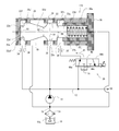
- FIG. 1 is a schematic configuration diagram of a hydraulic system provided with a relief valve as a hydraulic control valve according to the first embodiment, and is a diagram when the relief valve is in a high setting pressure state.
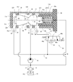
- FIG. 2 is a schematic block diagram of the hydraulic system of FIG. 1 when the relief valve is in the high setting pressure state.
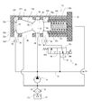
- FIG. 3 is a schematic configuration diagram of the hydraulic system of FIG. 1 when the relief valve is in a low setting pressure state.
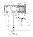
- FIG. 4 is a schematic configuration diagram of the hydraulic system of FIG. 1 when the relief valve is in a low setting pressure state.
- FIG. 5 is a schematic configuration diagram of a hydraulic system provided with a relief valve as a hydraulic control valve according to the second embodiment, and is a view when the relief valve is in a high setting pressure state.
- FIG. 5 is a schematic configuration diagram of a hydraulic system provided with a relief valve as a hydraulic control valve according to the second embodiment, and is a view when the relief valve is in a high setting pressure state.
- FIG. 6 is a schematic block diagram of the hydraulic system of FIG. 5 when the relief valve is in the high setting pressure state.
- FIG. 7 is a schematic configuration diagram of the hydraulic system of FIG. 5 when the relief valve is in the low setting pressure state.
- FIG. 8 is a schematic configuration diagram of the hydraulic system of FIG. 5 when the relief valve is in the low setting pressure state.
- a relief valve 10 as a hydraulic control valve according to a first embodiment will be described based on FIGS. 1 to 4.
- this indication is not limited to being applied to a relief valve, It is applicable to various hydraulic control valves.
- the hydraulic system provided with the relief valve 10 which concerns on 1st Embodiment at FIGS. 1-4 is shown.
- the relief valve 10 is a valve with a relief pressure change function (setting pressure change function).
- the relief valve 10 is equipped in the hydraulic system of the vehicle in order to adjust and control the pressure of the supply flow path 12 for supplying hydraulic oil (hereinafter, oil) to the clutch device CA of the automatic transmission (AT).
- oil hydraulic oil
- the relief valve 10 may be used for adjusting the pressure of the oil supply flow path to each part of the engine.
- the hydraulic control valve according to the present disclosure can be used in various applications.
- the oil pump 14 sucks the oil OIL stored in the oil pan 16 through the suction flow passage 18 (through the oil filter 19) to supply the supply flow passage 12. Discharge toward the clutch device CA.
- the relief valve 10 is disposed in the path of the supply flow passage 12 downstream of the oil pump 14.
- the oil pump 14 is comprised so that it may operate
- the relief valve 10 includes a valve body 20, a valve body 22, a spring 24, and an introduction amount variable device 26.
- the valve body 20 includes a body body 28 and a cap member 30. By attaching and fixing the cap member 30 to the body main body 28, they are integrated and an internal space 32 is defined between them.
- the internal space 32 of the valve body 20 is substantially cylindrical and has an axis 32a.
- the valve body 22 is movably disposed in a direction (axial direction) along the axis 32a.
- the valve body 22 has an axis substantially coinciding with the axis 32 a when in the internal space 32.
- a first introduction port 34, a second introduction port 36, an inflow port 38, and an exhaust port 40 are further defined.
- a pressure release hole 42 for releasing the back pressure acting on the valve body 22 is defined.
- the pressure relief holes 42 are provided along the axis 32 a of the internal space 32, but can be provided at various positions so that the valve body 22 is properly movable in the internal space 32.
- Each of the ports 34, 36, 38, 40 and the pressure release hole 42 is individually formed to communicate with the internal space 32. However, in order to ensure a suitable flow of oil from the ports 34, 36, 38, 40 into the interior space 32, as shown in FIGS.
- the ports 34, 36, 38 in the axial direction of the interior space, the ports 34, 36, 38 A substantially annular space through which oil can flow is formed around the inner space at a position opposite to each of 40.
- the first introduction port 34, the second introduction port 36, the inflow port 38, and the discharge port 40 are formed in the body main body 28, and the pressure release hole 42 is formed in the cap member 30, These do not limit the configuration of each member.
- Two ports, a first introduction port 34 and a second introduction port 36, are separately provided in the main body 28 as introduction ports configured to be capable of introducing oil into the internal space 32.
- the first introduction port 34 is always in communication with the supply channel 12.
- the second introduction port 36 can communicate with the supply flow path 12 via the valve 44.
- the introduction amount variable device 26 (configured to change the introduction amount of oil to the second introduction port 36) includes the valve 44 and a part of an electronic control unit (hereinafter, ECU) described later. It is configured.
- ECU electronice control unit
- orifices 34 'and 36' are provided in each flow path of oil to the first introduction port 34 and the second introduction port 36. These orifices 34 ', 36' are provided to suppress pressure pulsations of the oil flowing to the introduction ports, and can be omitted in other configurations.
- the inflow port 38 is configured to be capable of inflowing the oil pressure-fed from the oil pump 14, and is always in communication with the supply flow path 12 like the first introduction port 34.
- the discharge port is configured to be able to discharge the oil flowing into the internal space 32.
- the discharge port 40 and the pressure release hole 42 are respectively in communication with the suction passage 18, but may be in direct communication with the oil pan 16, for example.
- the first inlet port 34 and the second inlet port 36 are formed in the valve body 20 so as to sandwich the inlet port 38 and the outlet port 40 in the axial direction of the internal space 32.
- the end area of the internal space 32 on the side where the first introduction port 34 is located is taken as the first end area, and the internal space on the side where the second introduction port 36 is located.
- the end area of 32 is called the second end area.
- valve body 22 is movably disposed in the axial direction of the internal space 32, as described above.
- the valve body 22 is also substantially cylindrical.
- the valve body 22 is movably disposed in the internal space 32 but substantially fitted into the valve body 20.
- the valve body 20 and the valve body 22 are respectively dimensioned so as to be airtight between them.
- a coil spring 24 is arranged in the second end region.
- the coil spring 24 is provided as a biasing member that biases the valve body 22 from the second end region side to the first end region side along the axial direction of the internal space 32.
- the biasing force of the coil spring 24 biases the valve body 22 in the closing direction of the inflow port 38. That is, the coil spring 24 urges the valve body 22 to the non-ejectable position side that disables the discharge of the oil from the discharge port 40.
- the valve body 22 when the pressure of the oil introduced from the first introduction port 34 overcomes the biasing force of the coil spring 24 as described below, the valve body 22 is in the non-discharge position side or the first end region From the side, it is moved along the axial direction to the second end region side. Thereby, the valve body 22 can be moved from the non-discharge position side or the first end region side to the position to open the inflow port 38, whereby oil can flow into the internal space through the inflow port 38, As a result, the oil can be discharged from the discharge port 40.
- the position of the valve body 22 that enables the oil to be discharged from the discharge port 40 will be referred to as a drainable position.
- the valve body 22 is movable between the dischargeable position and the non-dischargeable position.
- the valve body 22 opens the inflow port 38 at the dischargeable position to allow oil to flow from there into the internal space, and closes the inflow port 38 at the nondischarge position and from there to the internal space Block the flow of oil.
- the dischargeable position of the valve body 22 is a position where the inflow port and the discharge port are in communication with each other, and the discharge impossible position of the valve body 22 is a disconnection state of the inflow port and the discharge port (blocked state).
- the dischargeable position corresponds to a first position in the technology of the present disclosure
- the non-discharge position corresponds to a second position in the technology of the present disclosure.
- the valve body 22 has a first end 22a positioned in the non-ejectable position side, that is, the first end area side, and a second end 22b positioned in the second area. And. When in the non-ejecting position as shown in FIG. 1, the valve body 22 is configured to close the inflow port 38 at a first diameter portion 22c having a maximum diameter (first diameter) D1.
- a second diameter D2 shorter than the first diameter D1 is provided between the first end 22a and the second end 22b, particularly on the first end 22a side of the first diameter portion 22c.
- the diameter portion 22 d is formed.
- the second diameter D2 of the second diameter portion 22d changes along the axial direction of the valve body 22. Therefore, the inflow port 38 communicates with the space around the second diameter portion 22d of the internal space 32, as described above, by moving the valve body 22 from the undischargeable position to the dischargeable position, and the space Can communicate with the discharge port 40.
- the first end 22a of the valve body 22 is formed to have a third diameter 22f having a third diameter D3 smaller than the first diameter D1.
- An intermediate diameter portion 22c 'having a first diameter is formed between the third diameter portion 22f and the second diameter portion 22d.
- a surface (hereinafter, first axial surface) 22af facing in the axial direction between the third diameter portion 22f and the middle diameter portion 22c ' is an inner portion from the first introduction port 34.
- the oil introduced into the space 32 can function as a first pressure receiving surface 22 e that can receive a force from the non-dischargeable position side to the dischargeable position side.
- the first axial surface 22 af is formed to face the first axial direction among the axial directions when the valve body 22 is in the internal space 32.
- the first axial surface 22af is an annular surface.
- the end surface 22a 'of the first end 22a abuts on the inner surface of the valve body 20 (that is, the surface that defines the internal space 32).
- the end face 22a ' also functions as the first pressure receiving face 22e.
- the non-ejectable position of the valve body 22 and the non-ejectable position both have a certain range (axial direction stroke).
- the end surface 22a ' can function as a first pressure receiving surface. That is, when the end face 22a 'of the first end 22a of the valve body 22 in the non-ejectable position is separated from the inner surface of the valve body 20, the first pressure receiving surface 22e is the first axial surface 22af; It is comprised by end surface 22a '.
- the end face 22a ' is circular and formed parallel to the first axial surface 22af and facing in the same direction (first axial direction) as the first axial surface 22af.
- the second end 22b side of the first diameter portion 22c of the valve body 22 is formed as a fourth diameter portion 22g having a fourth diameter D4 shorter than the first diameter D1.
- the surface (second axial surface) facing the axial direction between the first diameter portion 22 c and the fourth diameter portion 22 g is from the second introduction port 36 to the internal space 32. It functions as a second pressure receiving surface 22h capable of receiving a force from the dischargeable position side to the non-dischargeable position side from the introduced oil.
- the second axial surface is formed so as to face the second axial direction opposite to the first axial direction in the axial direction.
- the second pressure receiving surface 22h is an annular surface.
- the end of the fourth diameter portion 22g is movably disposed, in particular, in a cylindrical guide portion 30a disposed in the internal space 32 of the cap member 30, and the guide portion 30a extends in the axial direction of the internal space 32. Be guided.
- a coil spring 24 is disposed around the fourth diameter portion 22g.
- the second pressure receiving surface 22 h is also formed as an abutting surface with which one end of the coil spring 24 abuts. The other end of the coil spring abuts on the end face of the guide portion 30 a of the cap member 30.
- the second pressure receiving surface 22h is formed on the valve body 22 closer to the second end 22b than the first pressure receiving surface 22e of the first end 22a, and can receive an urging force from the coil spring 24. , Oil pressure or oil pressure can be received.
- the first pressure receiving surface 22e is formed to face in the opposite direction to the second pressure receiving surface 22h. Therefore, when the valve body 22 is in the internal space 32, the first pressure receiving surface 22e has a second axial direction from the non-discharge position side to the discharge possible position side from the oil introduced into the internal space from the first introduction port 34.
- the second pressure receiving surface 22h can move from the dischargeable side to the non-dischargeable side from the oil introduced into the internal space from the second introduction port 36 (opposite to the second axial direction). Can be subjected to a first axial force.
- the operation of the control valve 44 in the relief valve 10 having the above-described configuration is controlled by the aforementioned ECU (not shown).
- the ECU includes an arithmetic unit (e.g., CPU), a storage device (e.g., ROM, RAM), an A / D converter, an input / output port, and the like, and has a so-called computer configuration.
- Various sensors such as an engine rotational speed sensor and an engine load sensor are connected to the input port (since the engine is mounted on a vehicle as a power source). Then, here, the ECU adjusts the hydraulic pressure of the supply flow passage 12 according to a predetermined program according to the value detected (acquired) based on the output of the engine rotational speed sensor, the engine load sensor, etc.
- the relief valve 10 is configured to variably set the setting pressure in two stages of the high setting pressure state and the low setting pressure state. Switching between the high set pressure state and the low set pressure state is performed by controlling the operation of the control valve 44. Switching control between the high set pressure state and the low set pressure state is performed based on the result of comparing the engine torque calculated (obtained) based on the outputs of the various sensors with a predetermined torque. Ru. The predetermined torque is determined based on whether or not the engaging pressure of the clutch device CA needs to be equal to or higher than the predetermined pressure.
- the control valve 44 is controlled so that the high setting pressure state is established, and the engine torque becomes the engagement pressure of the clutch
- the control valve 44 is controlled to be in the low set pressure state when it is a torque that may be less than the pressure. More specifically, here, the control valve 44 is de-energized when in the high set pressure state, and is controlled in the low set pressure state.
- a part of the ECU serves as a valve control means configured to control the operation of the valve 44.
- the ECU also controls the operation of each unit such as the injector of the engine according to a predetermined program according to the engine operating state.
- FIGS. 1 and 2 show the relief valve 10 in a state where the set pressure of the relief pressure is high, that is, in the high set pressure state, and shows the operating state of the control valve 44 in the high set pressure state.
- 3 and 4 show the relief valve 10 in a state where the set pressure of the relief pressure is low, that is, in the low set pressure state, and shows the operating state of the control valve 44 in the low set pressure state.
- the control valve 44 is a spool type solenoid valve provided with a supply port 44a for connecting the second introduction port 36 to the supply flow path 12 and a drain port 44b for connecting the second introduction port 36 to the drain flow path 44c.
- the control valve 44 may be a solenoid valve of another configuration.
- the control valve 44 In the high set pressure state of FIGS. 1 and 2, the control valve 44 is in the open state, and oil is introduced into the second introduction port 36 as indicated by the arrow A1. Therefore, the combined force RF of the biasing force F of the coil spring 24 and the hydraulic pressure (hereinafter, closing pressure) (pressure per unit area P1 ⁇ area of the second pressure receiving surface 22h) CP by oil introduced from the second introduction port 36
- the valve body 22 is located at a position corresponding to the balance between oil pressure introduced from the first introduction port 34 (hereinafter, release pressure) (pressure per unit area P1 ⁇ area of the first pressure receiving surface 22e) OP. , Can be moved and positioned in the interior space 32.
- FIG. 1 shows the relief valve 10 in a state where the release pressure OP loses to the resultant force RF and the valve body 22 is in the non-ejectable position.
- the inflow port 38 is closed by the first diameter portion 22 c of the valve body 22.
- FIG. 2 shows the relief valve 10 with the valve body 22 in the ejectable position as a result of the release pressure OP overcoming the resultant force RF when the valve body is in the non-ejectable position.
- the inflow port 38 is opened, and the oil can flow into the internal space through the inflow port 38, and thus the inflowing oil is discharged upstream of the pump 14 through the discharge port (arrow in FIG. 2) See A2).
- the closing pressure CP is added to the biasing force F of the coil spring 48 as a force against the release pressure OP, so the setting pressure of the relief pressure becomes high.
- FIG. 3 shows the relief valve 10 in a state where the release pressure OP is lost to the biasing force F and the valve body 22 is in the non-ejectable position.
- the relief valve 10 has the above-described configuration, and in particular, the second pressure receiving surface 22h for receiving the hydraulic pressure introduced through the control valve 44 when the control valve 44 is opened is always It is formed to face in the opposite direction to the first pressure receiving surface 22e that receives the hydraulic pressure.
- the direction of the force acting on the valve body 22 from the coil spring 24 and the direction of the force acting on the valve body 22 through the second pressure receiving surface are generally the same.
- a control valve 44 is provided to make the amount of oil introduced into the second introduction port 36 variable. Therefore, the relief valve 10 has a configuration for varying the set pressure, that is, the relief pressure, and has a configuration different from that of the relief valve of Patent Document 1 in terms of the configuration.
- the relief valve 10 has a first pressure receiving surface 22e on the first end 22a side and a second pressure receiving surface 22h on the second end 22b side, and the second pressure receiving surface 22h is a coil spring 24. Serves as a contact surface against which one end of the As described above, since the surface receiving the force from the coil spring and the second pressure receiving surface receiving the oil pressure from the oil introduced through the second introduction port 36 are the same, the relief valve 10 is excellent in the miniaturization thereof. .
- the suction port 38 is provided separately from the first introduction port 34. Therefore, when the valve body 22 is in the non-ejecting position, the suction port 38 can be closed by the first diameter portion 22 c of the valve body 22 having the first diameter D1 which is the largest diameter. Therefore, in the relief valve 10, when the valve body 22 is in the non-ejectable position, oil can be prevented from being introduced into the internal space 32 through the inflow port 38, and the valve body 22 is surplus from the oil. It can prevent you from receiving power.
- the oil introduced from the first introduction port 34 into the internal space 32 is provided such that the first introduction port 34 also functions as a suction port and the valve body is in the dischargeable position.
- the relief valve 10 can be changed in this way, without excluding the configuration for being discharged from the discharge port. The same applies to the relief valve 110 of the second embodiment described below.
- Second Embodiment A relief valve 110 as a hydraulic pressure control valve according to a second embodiment will be described based on FIG. 5 to FIG.
- differences between the relief valve 110 according to the second embodiment and the relief valve 10 according to the first embodiment will be mainly described.
- the relief valve 110 of the second embodiment also exhibits the same effects as the relief valve 10 of the first embodiment.
- the second pressure receiving surface 22h at the second end 22b positioned on the dischargeable position side of the valve body 22 is independent of the contact surface 22j with which the coil spring 24 abuts. It is formed.
- An abutment surface 22j is formed on the end face 22b 'of the second end 22b.
- the end surface 22b 'of the second end 22b is parallel to the second axial surface, that is, the second pressure receiving surface 22h, and faces in the same direction (second axial direction) as the second pressure receiving surface 22h. It is formed.
- the coil spring 24 is disposed in a cylindrical guide portion 30 a disposed in the internal space 32 of the cap member 30.
- the end face 22b ' is circular here.
- the axial length of the fourth diameter portion 22g is shortened as compared with the relief valve 10 of the first embodiment.
- the valve body 22 can be reduced.
- the total length of the relief valve 110 tends to be longer than the relief valve 10 according to the first embodiment.
- the degree of reduction of the valve body 22 and the degree of reduction of the relief valve as a whole may be set in consideration of cost, selection design of members, and the like. The same applies to the relief valve 10 according to the first embodiment.
- FIGS. 5 and 6 show a state where the setting pressure of the relief pressure is high, that is, an operating state in a high setting pressure state
- FIGS. 7 and 8 show the setting pressure of the relief pressure. Indicates the operating condition at the low setting pressure condition.
- 5 and 7 show a state in which the valve body 22 is in the non-dischargeable position
- FIGS. 6 and 8 show a state in which the valve body 22 is in the dischargeable position.
- the flow of oil in each state of FIGS. 5 to 8, the control of the control valve 44, etc. are as described based on FIGS. 1 to 4 with respect to the relief valve 10 of the first embodiment. I omit it.
- the first pressure receiving surface and the second pressure receiving surface are not limited to be formed to face in opposite directions with respect to each other, and the first pressure receiving surface may be formed of hydraulic oil introduced into the internal space from the first introduction port. It can be modified to have various configurations capable of receiving a force from the non-discharge position side to the dischargeable position side, and the second pressure receiving surface can be discharged from the hydraulic oil introduced into the internal space from the second introduction port It can be modified to have various configurations capable of receiving a force from the position side to the non-ejecting position side.
- the first pressure receiving surface and the second pressure receiving surface are planes orthogonal to the axis of the valve body or the axis of the internal space of the relief valve in the above embodiment, but are inclined obliquely thereto It is also possible to be a face.
- a plurality of second introduction ports may be provided, a second pressure receiving surface may be provided for each second introduction port, and the relief valve may be configured to switch and set the set pressure in three or more stages.
- the additionally provided second introduction port may be formed in the valve body in the same manner as the suction port.
- the additional pressure receiving surface for receiving the oil pressure from the oil introduced from the additionally provided second introduction port is formed by providing the valve body with an additional diameter portion having a diameter shorter than the maximum diameter. be able to.
- the hydraulic control valve of the present disclosure is useful in that the set pressure is changed.
Landscapes
- Engineering & Computer Science (AREA)
- General Engineering & Computer Science (AREA)
- Mechanical Engineering (AREA)
- Physics & Mathematics (AREA)
- Fluid Mechanics (AREA)
- Safety Valves (AREA)
- Fluid-Pressure Circuits (AREA)
- Fluid-Driven Valves (AREA)
- Mechanically-Actuated Valves (AREA)
- Multiple-Way Valves (AREA)
Abstract
L'invention concerne une vanne de commande de pression hydraulique, laquelle vanne comprend : un corps de vanne délimitant un espace interne, des premier et second orifices d'introduction, et un orifice de décharge ; une aiguille de vanne disposée de façon à être apte à se déplacer entre une position de décharge possible et une position de décharge impossible ; un élément qui pousse l'aiguille de vanne vers le côté de position de décharge impossible ; et un dispositif apte à faire varier une quantité d'huile de fonctionnement introduite dans le second orifice d'introduction. L'aiguille de vanne comporte une surface de réception de pression qui accepte, à partir de l'huile de fonctionnement provenant du premier orifice d'introduction, une force dirigée vers le côté de position de décharge possible, et une surface de réception de pression qui accepte, à partir de l'huile de fonctionnement provenant du second orifice d'introduction, une force dirigée vers le côté de position de décharge impossible.
Priority Applications (2)
| Application Number | Priority Date | Filing Date | Title |
|---|---|---|---|
| CN201880073794.0A CN111344494B (zh) | 2017-11-15 | 2018-11-07 | 油压控制阀 |
| PH12020550618A PH12020550618A1 (en) | 2017-11-15 | 2020-05-12 | Hydraulic pressure control valve |
Applications Claiming Priority (2)
| Application Number | Priority Date | Filing Date | Title |
|---|---|---|---|
| JP2017219911A JP7091634B2 (ja) | 2017-11-15 | 2017-11-15 | 油圧制御弁 |
| JP2017-219911 | 2017-11-15 |
Publications (1)
| Publication Number | Publication Date |
|---|---|
| WO2019098103A1 true WO2019098103A1 (fr) | 2019-05-23 |
Family
ID=66539650
Family Applications (1)
| Application Number | Title | Priority Date | Filing Date |
|---|---|---|---|
| PCT/JP2018/041302 Ceased WO2019098103A1 (fr) | 2017-11-15 | 2018-11-07 | Vanne de commande de pression hydraulique |
Country Status (4)
| Country | Link |
|---|---|
| JP (1) | JP7091634B2 (fr) |
| CN (1) | CN111344494B (fr) |
| PH (1) | PH12020550618A1 (fr) |
| WO (1) | WO2019098103A1 (fr) |
Cited By (1)
| Publication number | Priority date | Publication date | Assignee | Title |
|---|---|---|---|---|
| CN116472420A (zh) * | 2021-05-16 | 2023-07-21 | 无锡星驱科技有限公司 | 一种液压控制阀、液压控制系统及变速器 |
Citations (6)
| Publication number | Priority date | Publication date | Assignee | Title |
|---|---|---|---|---|
| US2890715A (en) * | 1955-08-26 | 1959-06-16 | Warner Swasey Co | Multi-pressure relief valve |
| JPS63225701A (ja) * | 1987-02-18 | 1988-09-20 | ハイルマイア ウント バインライン ファブリク フュル オエル ハイドロリク ゲーエムベーハー ウント コンパニー,カーゲー | 液圧制御装置 |
| JPH01120405A (ja) * | 1987-11-04 | 1989-05-12 | Sumitomo Heavy Ind Ltd | コンポジットバルブ |
| JPH04105676U (ja) * | 1991-02-26 | 1992-09-11 | 株式会社アツギユニシア | オイルリリーフ装置 |
| JPH0624276U (ja) * | 1992-08-31 | 1994-03-29 | エヌオーケー株式会社 | リリーフバルブ |
| JP2009191634A (ja) * | 2008-02-12 | 2009-08-27 | Toyota Motor Corp | 内燃機関の潤滑装置 |
Family Cites Families (11)
| Publication number | Priority date | Publication date | Assignee | Title |
|---|---|---|---|---|
| US2293118A (en) * | 1940-02-12 | 1942-08-18 | Vickerts Inc | Power transmission |
| JPS4631889Y1 (fr) * | 1968-10-12 | 1971-11-04 | ||
| JPS5917074A (ja) * | 1982-07-16 | 1984-01-28 | Hitachi Constr Mach Co Ltd | ロジツク弁 |
| FR2785401B1 (fr) * | 1998-07-07 | 2005-08-05 | Luk Getriebe Systeme Gmbh | Distributeur regulateur de flux volumique |
| JP2001193854A (ja) * | 2000-01-06 | 2001-07-17 | Smc Corp | パイロット形2ポート弁 |
| AU2001294572A1 (en) * | 2000-09-19 | 2002-05-21 | Curtiss Wright Corporation | Pressure releif valve actuated by pilot valve |
| CN101560999B (zh) * | 2009-05-14 | 2011-04-13 | 浙江大学 | 大流量快速节流比例阀 |
| JP5483567B2 (ja) * | 2010-03-26 | 2014-05-07 | アイシン精機株式会社 | リリーフ圧力変更機能付きリリーフバルブ |
| JP4942833B2 (ja) * | 2010-04-07 | 2012-05-30 | アイシン精機株式会社 | リリーフ圧力変更機能付きリリーフバルブ |
| JP5582341B2 (ja) * | 2010-07-07 | 2014-09-03 | アイシン精機株式会社 | リリーフ圧変更機能付きリリーフバルブ |
| DE102013013231A1 (de) * | 2013-08-08 | 2015-02-12 | Man Diesel & Turbo Se | Ventilanordnung für eine Kraftstoffversorgungsanlage und Kraftstoffversorgungsanlage |
-
2017
- 2017-11-15 JP JP2017219911A patent/JP7091634B2/ja active Active
-
2018
- 2018-11-07 CN CN201880073794.0A patent/CN111344494B/zh active Active
- 2018-11-07 WO PCT/JP2018/041302 patent/WO2019098103A1/fr not_active Ceased
-
2020
- 2020-05-12 PH PH12020550618A patent/PH12020550618A1/en unknown
Patent Citations (6)
| Publication number | Priority date | Publication date | Assignee | Title |
|---|---|---|---|---|
| US2890715A (en) * | 1955-08-26 | 1959-06-16 | Warner Swasey Co | Multi-pressure relief valve |
| JPS63225701A (ja) * | 1987-02-18 | 1988-09-20 | ハイルマイア ウント バインライン ファブリク フュル オエル ハイドロリク ゲーエムベーハー ウント コンパニー,カーゲー | 液圧制御装置 |
| JPH01120405A (ja) * | 1987-11-04 | 1989-05-12 | Sumitomo Heavy Ind Ltd | コンポジットバルブ |
| JPH04105676U (ja) * | 1991-02-26 | 1992-09-11 | 株式会社アツギユニシア | オイルリリーフ装置 |
| JPH0624276U (ja) * | 1992-08-31 | 1994-03-29 | エヌオーケー株式会社 | リリーフバルブ |
| JP2009191634A (ja) * | 2008-02-12 | 2009-08-27 | Toyota Motor Corp | 内燃機関の潤滑装置 |
Cited By (2)
| Publication number | Priority date | Publication date | Assignee | Title |
|---|---|---|---|---|
| CN116472420A (zh) * | 2021-05-16 | 2023-07-21 | 无锡星驱科技有限公司 | 一种液压控制阀、液压控制系统及变速器 |
| US12398817B2 (en) | 2021-05-16 | 2025-08-26 | Wuxi Infimotion Technology Co., Ltd. | Hydraulic control valve, hydraulic control system, and transmission |
Also Published As
| Publication number | Publication date |
|---|---|
| JP2019090484A (ja) | 2019-06-13 |
| JP7091634B2 (ja) | 2022-06-28 |
| CN111344494A (zh) | 2020-06-26 |
| PH12020550618A1 (en) | 2021-02-15 |
| CN111344494B (zh) | 2022-09-23 |
Similar Documents
| Publication | Publication Date | Title |
|---|---|---|
| JP6167004B2 (ja) | コントロール弁 | |
| US9732863B2 (en) | Fluid control valve | |
| JP5483567B2 (ja) | リリーフ圧力変更機能付きリリーフバルブ | |
| US7263924B2 (en) | Hydraulic circuit and its valve gear | |
| US12055225B2 (en) | Fluid control device | |
| JP2010520421A (ja) | ハイドロリックシステム | |
| US10107309B2 (en) | Load sensing valve device | |
| WO2019098103A1 (fr) | Vanne de commande de pression hydraulique | |
| JP5561528B2 (ja) | リリーフ圧力変更機能付きリリーフバルブ | |
| US20160108781A1 (en) | Variable-flow rate oil pump | |
| CN106438135B (zh) | 泄压阀装置 | |
| US7766042B2 (en) | Direct operated cartridge valve assembly | |
| KR101491267B1 (ko) | 더블 클러치 변속기용 유압 제어 장치 | |
| JP2019056464A (ja) | 流量制御弁 | |
| JP2016223498A (ja) | 流体制御装置 | |
| JP5655960B2 (ja) | 油圧制御回路 | |
| JP2017020562A (ja) | リリーフバルブ | |
| KR102805994B1 (ko) | 전자 밸브 및 작업 기계 | |
| CN110998151A (zh) | 液压系统 | |
| JP2013117293A (ja) | 流量調整弁 | |
| JP2010090807A (ja) | 二連式ベーンポンプ | |
| JP6487749B2 (ja) | オイルポンプ | |
| US20190376534A1 (en) | Electromagnetic pressure reducing valve and fluid pressure control device including electromagnetic pressure reducing valve | |
| JP2021011829A (ja) | 作動油供給装置 | |
| WO2019058814A1 (fr) | Vanne de commande |
Legal Events
| Date | Code | Title | Description |
|---|---|---|---|
| 121 | Ep: the epo has been informed by wipo that ep was designated in this application |
Ref document number: 18878947 Country of ref document: EP Kind code of ref document: A1 |
|
| NENP | Non-entry into the national phase |
Ref country code: DE |
|
| 122 | Ep: pct application non-entry in european phase |
Ref document number: 18878947 Country of ref document: EP Kind code of ref document: A1 |