WO2019111390A1 - Outil électrique - Google Patents
Outil électrique Download PDFInfo
- Publication number
- WO2019111390A1 WO2019111390A1 PCT/JP2017/044063 JP2017044063W WO2019111390A1 WO 2019111390 A1 WO2019111390 A1 WO 2019111390A1 JP 2017044063 W JP2017044063 W JP 2017044063W WO 2019111390 A1 WO2019111390 A1 WO 2019111390A1
- Authority
- WO
- WIPO (PCT)
- Prior art keywords
- fluid
- pressure
- return
- piston
- flow channel
- Prior art date
- Legal status (The legal status is an assumption and is not a legal conclusion. Google has not performed a legal analysis and makes no representation as to the accuracy of the status listed.)
- Ceased
Links
Images


Classifications
-
- B—PERFORMING OPERATIONS; TRANSPORTING
- B25—HAND TOOLS; PORTABLE POWER-DRIVEN TOOLS; MANIPULATORS
- B25B—TOOLS OR BENCH DEVICES NOT OTHERWISE PROVIDED FOR, FOR FASTENING, CONNECTING, DISENGAGING, OR HOLDING
- B25B27/00—Hand tools, specially adapted for fitting together or separating parts or objects whether or not involving some deformation, not otherwise provided for
- B25B27/02—Hand tools, specially adapted for fitting together or separating parts or objects whether or not involving some deformation, not otherwise provided for for connecting objects by press fit or detaching same
- B25B27/10—Hand tools, specially adapted for fitting together or separating parts or objects whether or not involving some deformation, not otherwise provided for for connecting objects by press fit or detaching same inserting fittings into hoses
-
- B—PERFORMING OPERATIONS; TRANSPORTING
- B25—HAND TOOLS; PORTABLE POWER-DRIVEN TOOLS; MANIPULATORS
- B25F—COMBINATION OR MULTI-PURPOSE TOOLS NOT OTHERWISE PROVIDED FOR; DETAILS OR COMPONENTS OF PORTABLE POWER-DRIVEN TOOLS NOT PARTICULARLY RELATED TO THE OPERATIONS PERFORMED AND NOT OTHERWISE PROVIDED FOR
- B25F5/00—Details or components of portable power-driven tools not particularly related to the operations performed and not otherwise provided for
- B25F5/005—Hydraulic driving means
-
- B—PERFORMING OPERATIONS; TRANSPORTING
- B25—HAND TOOLS; PORTABLE POWER-DRIVEN TOOLS; MANIPULATORS
- B25B—TOOLS OR BENCH DEVICES NOT OTHERWISE PROVIDED FOR, FOR FASTENING, CONNECTING, DISENGAGING, OR HOLDING
- B25B25/00—Implements for fastening, connecting or tensioning of wire or strip
-
- B—PERFORMING OPERATIONS; TRANSPORTING
- B23—MACHINE TOOLS; METAL-WORKING NOT OTHERWISE PROVIDED FOR
- B23D—PLANING; SLOTTING; SHEARING; BROACHING; SAWING; FILING; SCRAPING; LIKE OPERATIONS FOR WORKING METAL BY REMOVING MATERIAL, NOT OTHERWISE PROVIDED FOR
- B23D15/00—Shearing machines or shearing devices cutting by blades which move parallel to themselves
- B23D15/12—Shearing machines or shearing devices cutting by blades which move parallel to themselves characterised by drives or gearings therefor
- B23D15/14—Shearing machines or shearing devices cutting by blades which move parallel to themselves characterised by drives or gearings therefor actuated by fluid or gas pressure
-
- B—PERFORMING OPERATIONS; TRANSPORTING
- B25—HAND TOOLS; PORTABLE POWER-DRIVEN TOOLS; MANIPULATORS
- B25B—TOOLS OR BENCH DEVICES NOT OTHERWISE PROVIDED FOR, FOR FASTENING, CONNECTING, DISENGAGING, OR HOLDING
- B25B27/00—Hand tools, specially adapted for fitting together or separating parts or objects whether or not involving some deformation, not otherwise provided for
- B25B27/14—Hand tools, specially adapted for fitting together or separating parts or objects whether or not involving some deformation, not otherwise provided for for assembling objects other than by press fit or detaching same
- B25B27/146—Clip clamping hand tools
-
- B—PERFORMING OPERATIONS; TRANSPORTING
- B25—HAND TOOLS; PORTABLE POWER-DRIVEN TOOLS; MANIPULATORS
- B25F—COMBINATION OR MULTI-PURPOSE TOOLS NOT OTHERWISE PROVIDED FOR; DETAILS OR COMPONENTS OF PORTABLE POWER-DRIVEN TOOLS NOT PARTICULARLY RELATED TO THE OPERATIONS PERFORMED AND NOT OTHERWISE PROVIDED FOR
- B25F5/00—Details or components of portable power-driven tools not particularly related to the operations performed and not otherwise provided for
-
- B—PERFORMING OPERATIONS; TRANSPORTING
- B25—HAND TOOLS; PORTABLE POWER-DRIVEN TOOLS; MANIPULATORS
- B25F—COMBINATION OR MULTI-PURPOSE TOOLS NOT OTHERWISE PROVIDED FOR; DETAILS OR COMPONENTS OF PORTABLE POWER-DRIVEN TOOLS NOT PARTICULARLY RELATED TO THE OPERATIONS PERFORMED AND NOT OTHERWISE PROVIDED FOR
- B25F5/00—Details or components of portable power-driven tools not particularly related to the operations performed and not otherwise provided for
- B25F5/02—Construction of casings, bodies or handles
-
- H—ELECTRICITY
- H01—ELECTRIC ELEMENTS
- H01R—ELECTRICALLY-CONDUCTIVE CONNECTIONS; STRUCTURAL ASSOCIATIONS OF A PLURALITY OF MUTUALLY-INSULATED ELECTRICAL CONNECTING ELEMENTS; COUPLING DEVICES; CURRENT COLLECTORS
- H01R43/00—Apparatus or processes specially adapted for manufacturing, assembling, maintaining, or repairing of line connectors or current collectors or for joining electric conductors
- H01R43/04—Apparatus or processes specially adapted for manufacturing, assembling, maintaining, or repairing of line connectors or current collectors or for joining electric conductors for forming connections by deformation, e.g. crimping tool
- H01R43/042—Hand tools for crimping
- H01R43/0428—Power-driven hand crimping tools
-
- B—PERFORMING OPERATIONS; TRANSPORTING
- B23—MACHINE TOOLS; METAL-WORKING NOT OTHERWISE PROVIDED FOR
- B23D—PLANING; SLOTTING; SHEARING; BROACHING; SAWING; FILING; SCRAPING; LIKE OPERATIONS FOR WORKING METAL BY REMOVING MATERIAL, NOT OTHERWISE PROVIDED FOR
- B23D29/00—Hand-held metal-shearing or metal-cutting devices
- B23D29/002—Hand-held metal-shearing or metal-cutting devices for cutting wire or the like
-
- H—ELECTRICITY
- H01—ELECTRIC ELEMENTS
- H01R—ELECTRICALLY-CONDUCTIVE CONNECTIONS; STRUCTURAL ASSOCIATIONS OF A PLURALITY OF MUTUALLY-INSULATED ELECTRICAL CONNECTING ELEMENTS; COUPLING DEVICES; CURRENT COLLECTORS
- H01R43/00—Apparatus or processes specially adapted for manufacturing, assembling, maintaining, or repairing of line connectors or current collectors or for joining electric conductors
- H01R43/04—Apparatus or processes specially adapted for manufacturing, assembling, maintaining, or repairing of line connectors or current collectors or for joining electric conductors for forming connections by deformation, e.g. crimping tool
- H01R43/042—Hand tools for crimping
- H01R43/0427—Hand tools for crimping fluid actuated hand crimping tools
Definitions
- the present invention relates to an electric power tool, and more particularly, to a piston which is reciprocally accommodated in a cylinder provided in a main body and pushed by a fluid pressure, and connected to the tip of the main body to
- the present invention relates to a power tool that includes a tool head that performs a predetermined operation by pressing and that is driven by an electric motor.
- a power tool described in Patent Document 1 has been proposed.
- This electric power tool is a cordless type provided with a detachable battery in the main body, and the hydraulic pump is driven by the electric motor while the operator is pressing the start switch knob. The hydraulic pressure pushes the piston to close the tip of the base of the tool head.
- a tool head for crimping it can be used as a crimping tool for securing a crimp terminal to a wire or cable.
- a cutting tool head it can also be used as a cutting tool for cutting wires and cables.
- a power tool having an automatic retracting function for automatically returning the piston to the start position when the work is finished.
- the function can not be canceled when the automatic retraction function is not required, or a problem that it can not be stopped halfway during the operation of the automatic retraction function.
- the return valve Assuming that the return valve is operated to return the piston from the outside electrically, the function can be canceled or stopped halfway, but since a solenoid, a motor, etc. that operates the return valve electrically are required, Problems such as complication of structure, increase in weight, and increase in manufacturing cost may occur.
- the return valve may be closed when the start switch knob is pressed, and the return valve may be opened when the start switch knob is released.
- another problem may occur in that temporary holding can not be performed during operation.
- the present invention has been made in view of the above circumstances, and a simple structure using a hydraulic mechanism can realize an automatic retracting function for automatically returning the piston to the start position when the work is finished, and an automatic retracting function It is an object of the present invention to provide an electric power tool which can easily carry out the release of and the addition of a mechanism for performing a halfway stop.
- the problems are solved by the solutions disclosed below.
- the disclosed electric power tool is housed in a cylinder provided in a main body portion so as to be capable of reciprocating, and is pushed by a fluid pressure, and is connected to the tip of the main body portion and is operated by a predetermined pressure by the piston.
- An electric tool driven by an electric motor the return flow passage communicating the fluid from the cylinder to the fluid tank storing the fluid, and the return flow passage
- a pressure regulating valve which is disposed in the operation flow channel branched from the pressure regulation valve and which is in the open position when the pressure of the fluid in the return flow channel becomes equal to or more than a predetermined value; It is a requirement to include an operating pin pushed by the pressure of the fluid flowing in, and a return valve which is disposed in the return flow path and which becomes an open position by pushing of the operating pin.
- the piston is automatically moved to the start position when the predetermined work is completed by the simple mechanical structure using the hydraulic mechanism without providing the solenoid, the motor, etc. which operate the return valve electrically. It is possible to realize an automatic reverse function to return. In addition, it is possible to easily cancel the automatic reverse function and add a mechanism for stopping on the way.
- FIG. 6 is an enlarged view (schematic view) centering on a portion related to a mechanism for canceling an automatic retraction function of the piston of the electric power tool shown in FIG.
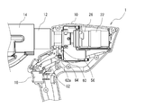
- FIG. 1 is a perspective view (schematic view) showing an example of the electric power tool 1
- FIG. 2 is a front view (schematic diagram).
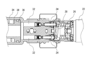
- FIG. 3 is a schematic view showing an example of an internal mechanism of the power tool 1.
- FIG. 4 is an enlarged view (schematic view) centering on a portion related to the pushing mechanism of the piston 36 of the electric power tool 1.
- members having the same function are denoted by the same reference numerals, and repeated description thereof may be omitted.
- the power tool 1 is a cordless type power tool which can be gripped and operated by a worker with one hand.
- the tool head at the tip is designed to be replaceable.
- the cable etc. and the crimping terminal can be used as a crimping tool for crimping by crimping.
- a tool head (not shown) having a cutter for cutting at the tip end, it can also be used as a cutting tool for cutting a cable or the like.
- a description will be given by taking the case of a crimping tool as an example.
- the electric power tool 1 is detachable from a gun-like main body 10 gripped by an operator, a mounting portion 12 provided at the tip end thereof, and a tool head 14 mounted exchangeably on the mounting portion 12 Rechargeable battery 16. Further, an electric motor 22 driven by the power supply of the battery 16 and a fluid pump (for example, oil pressure, which is driven by the electric motor 22 to pressurize a fluid (for example, hydraulic oil), A pump) 24, a control unit (not shown) for controlling the drive and the like, and the like are provided.
- a fluid pump for example, oil pressure, which is driven by the electric motor 22 to pressurize a fluid (for example, hydraulic oil), A pump
- a control unit for controlling the drive and the like, and the like are provided.
- the tool head 14 performs a predetermined operation by the pressure of the fluid pressurized by the fluid pump 24.
- a series of operations will be specifically described by taking the case where the tool head 14 performs a crimping operation as an example.
- the electric motor 22 is driven. At this time, a rotational force is transmitted from the electric motor 22 through the reduction mechanism 26, and is converted into a driving force of the direct-acting fluid pump 24 by the swash plate cam 28.
- the fluid pressurized by the fluid pump 24 flows through the discharge flow passage 32 and flows into a cylinder 34 provided in the main body 10.
- the piston 36 accommodated in the cylinder 34 so as to be capable of reciprocating is pushed in one direction (direction toward the tip of the main body 10).
- the operation arm 14 a of the tool head 14 is connected to the tip of the piston 36, and is pushed toward the tip of the main body 10 together with the piston 36. Therefore, by storing a cable or the like and a crimp terminal between the fixed arm 14b of the tool head 14 and the operation arm 14a, an effect of crimping these can be obtained.
- the present invention power is supplied from the battery 16 and the electric motor 22 is driven only while the start switch knob 18 provided on the main body 10 is pressed.
- the present invention is not limited to this configuration, and the drive of the electric motor 22 is started when the start switch knob 18 is pressed, and the electric motor 22 is started next when the start switch knob 18 is pressed next.
- the drive of the may be stopped.
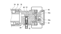
- FIG. 5 is an enlarged view (sectional view) of a plan view centering on a portion related to the mechanism performing the automatic retraction function
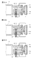
- FIG. 6 is an explanatory view for explaining the automatic retraction function.
- a return flow passage 40 for communicating the fluid from the cylinder 34 to a fluid reservoir (not shown) for storing the fluid.
- an operation flow channel 42 branched from the return flow channel 40 is provided, and a pressure regulating valve 44 which opens and closes the operation flow channel 42 in the middle of the operation flow channel 42 is provided.
- the pressure regulating valve 44 serves to open the operating flow channel 42 when the pressure of the fluid in the return flow channel 40 becomes equal to or higher than a predetermined value.
- the fluid pressurized by the fluid pump 24 continues in the cylinder 34 in a state in which the pushing motion of the piston 36 is stopped when the predetermined operation (as one example, the crimping operation) by the tool head 14 is finished.
- the pressure of the fluid in the cylinder 34 and in the return passage 40 communicating with the cylinder 34 becomes equal to or higher than a predetermined value set in advance. Therefore, the pressure regulating valve 44 is in the open position and the operation flow channel 42 is opened, so that the pressurized fluid flows from the inside of the return flow channel 40 into the operation flow channel 42.
- the tip end portion 46a protrudes outward from the operation flow channel 42 at a position downstream of the pressure regulating valve 44 (side away from the branch with the return flow channel 40).
- the operating pin 46 is provided so as to be able to reciprocate in the operating flow path 42 in the state where it is made to move.
- the operating pin 46 is normally urged in a direction toward the tip end portion 46 a into the operating channel 42 by the biasing member, and the operating channel 42 is opened, and the operating channel from the inside of the return channel 40 is opened.
- the return flow path 40 is provided with a return valve 48 for opening and closing the return flow path 40 at a position downstream of the branch with the operation flow path 42 (side away from the branch).
- the return valve 48 has a spherical valve body 48a, and normally urges the valve body 48a in one direction (here, a direction toward the inside of the operation flow path 42) in the closing position by the biasing member.
- the valve body 48a When the valve body 48a is pushed in the reverse direction (here, a direction toward the outside of the operation flow channel 42) by the tip portion 46a of the operation pin 46, it becomes an open position and opens the return flow channel 40. It has an action to
- the piston 36 is pushed in the reverse direction (the direction away from the tip of the main body 10). That is, a retracting function of returning the piston 36 to the start position is obtained.
- the fluid flows from the discharge passage 32 into the cylinder 34 and the fluid from the cylinder 34 flows out to the return passage 40. As a result, the piston 36 does not move in either direction.
- the tool head when the operator presses the start switch knob 18 of the main body unit 10 to operate the tool head 14 and perform a predetermined operation (such as pressure bonding), the tool head when the operation is completed.
- the movement of the 14 movable parts (as an example, the fixed arm 14b) is stopped (see FIG. 6A).
- the pressure of the fluid in the cylinder 34 and the return flow passage 40 communicating with the cylinder 34 becomes equal to or higher than a predetermined value.
- the pressure regulating valve 44 is opened and the operation flow channel 42 is opened, and the pressurized fluid flows from the inside of the return flow channel 40 into the operation flow channel 42 (see FIG. 6B).
- the automatic retraction function of the piston 36 can be realized by the simple mechanical structure, specifically, the simple hydraulic mechanism using the operation flow path, the on-off valve, and the like. Therefore, since it is not necessary to provide a solenoid, a motor, etc. which operate a return valve electrically, it becomes possible to solve the problem of the complication of a structure, the increase in a weight, the increase in manufacturing cost, etc.
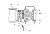
- FIG. 7 is an enlarged view (cross-sectional view) of a front view centering on a portion related to the mechanism that performs the release and the halfway stop of the automatic retraction function.
- an open channel 52 branched from the operation channel 42 is provided.
- the branch portion is provided at a position between the arrangement position of the pressure regulating valve 44 and the arrangement position of the operation pin 46.
- a pressure release valve 54 is provided to open and close the release flow path 52 in the middle of the flow path of the release flow path 52.
- the pressure release valve 54 has a spherical valve body 54a, and is normally biased in one direction such that the valve body 54a is in the closed position by the biasing member, and the valve 56 is actuated by the tip 56a of the release pin 56. When the body 54a is pushed in the reverse direction, it becomes an open position and serves to open the open channel 52.
- the cam performing the opening / closing operation of the opening flow channel 52 (here, the operation of setting the open position), that is, the operation (pushing operation) of the open pin 56 pushing the pressure release valve 54 to the open position. It has 60.
- the cam 60 is rotatably disposed and normally urged in one direction, and is opened to a predetermined position by rotating in a reverse direction (direction of arrow A) to a predetermined position. It acts to push 56, that is, it acts to bring the pressure release valve 54 to the open position.
- the following two configurations are provided as an operation unit for operating (rotating) the cam 60 to a predetermined position.
- a link unit 62 connected to the start switch knob 18 and converting movement of the start switch knob 18 into rotation of the cam 60 is provided.
- the worker stops pressing the start switch knob 18 the worker is again operated.
- the tip end portion 62a of the link portion 62 connected to the start switch knob 18 sets the cam 60 by pressing the start switch knob 18 (it is not necessary to continue pressing but may be pressed once).
- An action (rotation) to the position occurs. Therefore, the pressure release valve 54 is in the open position, and the automatic retraction function of the piston 36 can be stopped in the middle of operation. In this manner, the halfway stop mechanism of the automatic reverse function can be realized by the addition of a very simple configuration.
- a lever portion 64 having a large and small operation dimension and in contact with the cam 60 As an example, a cylindrical member which is disposed movably in the direction parallel to the rotation axis C of the cam 60 and which can contact the cam 60 with two working radii is used for the lever portion 64. According to this, by bringing the portion of the large action dimension of the lever portion 64 into contact with the cam 60, an action (rotation) of the cam 60 is generated.
- the portion of the lever portion 64 having a small working dimension may not be in contact with the cam 60, or may be in contact with the cam 60 to such an extent that the cam 60 does not move (rotate) to a predetermined position.
- the lever portion 64 is moved to one position before the start of the work, ie, before the start switch knob 18 is pressed, and the small working dimension portion does not abut on the cam 60 (or to the predetermined position). In the state of contact (not rotated), the cam 60 is not moved (rotated) to a predetermined position, so that the automatic retraction function can be activated. Conversely, if the lever portion 64 is moved to the other position before pressing the start switch knob 18 and a portion with a large working dimension is in contact with the cam 60, the cam 60 moves to a predetermined position. The action of (turning) occurs. Therefore, the pressure release valve 54 is in the open position, and the automatic retraction function of the piston 36 can be released. Thus, the release mechanism of the automatic retraction function can be realized by the addition of a very simple configuration.
- the predetermined work is completed by the simple mechanical structure using the hydraulic mechanism without providing the solenoid, the motor, etc. which operate the return valve electrically.
- the piston is automatically returned to the start position, an automatic retraction function can be realized.
- it is possible to easily cancel the automatic reverse function and add a mechanism for stopping on the way.
- the present invention is not limited to the embodiments described above, and various modifications can be made without departing from the present invention.
- a crimping tool has been described as an example of the present electric power tool, the present invention is not limited to this, and can be suitably applied to a cutting tool or the like.
Landscapes
- Engineering & Computer Science (AREA)
- Mechanical Engineering (AREA)
- Manufacturing & Machinery (AREA)
- Hand Tools For Fitting Together And Separating, Or Other Hand Tools (AREA)
- Surgical Instruments (AREA)
- Cold Cathode And The Manufacture (AREA)
- Drilling And Exploitation, And Mining Machines And Methods (AREA)
Abstract
Priority Applications (6)
| Application Number | Priority Date | Filing Date | Title |
|---|---|---|---|
| CN201780097447.7A CN111432985B (zh) | 2017-12-07 | 2017-12-07 | 电动工具 |
| AU2017441860A AU2017441860B2 (en) | 2017-12-07 | 2017-12-07 | Electric tool |
| EP17934073.2A EP3680067B1 (fr) | 2017-12-07 | 2017-12-07 | Outil électrique |
| US16/753,890 US11241780B2 (en) | 2017-12-07 | 2017-12-07 | Electric tool |
| KR1020207018769A KR102392840B1 (ko) | 2017-12-07 | 2017-12-07 | 전동 공구 |
| PCT/JP2017/044063 WO2019111390A1 (fr) | 2017-12-07 | 2017-12-07 | Outil électrique |
Applications Claiming Priority (1)
| Application Number | Priority Date | Filing Date | Title |
|---|---|---|---|
| PCT/JP2017/044063 WO2019111390A1 (fr) | 2017-12-07 | 2017-12-07 | Outil électrique |
Publications (1)
| Publication Number | Publication Date |
|---|---|
| WO2019111390A1 true WO2019111390A1 (fr) | 2019-06-13 |
Family
ID=66750130
Family Applications (1)
| Application Number | Title | Priority Date | Filing Date |
|---|---|---|---|
| PCT/JP2017/044063 Ceased WO2019111390A1 (fr) | 2017-12-07 | 2017-12-07 | Outil électrique |
Country Status (6)
| Country | Link |
|---|---|
| US (1) | US11241780B2 (fr) |
| EP (1) | EP3680067B1 (fr) |
| KR (1) | KR102392840B1 (fr) |
| CN (1) | CN111432985B (fr) |
| AU (1) | AU2017441860B2 (fr) |
| WO (1) | WO2019111390A1 (fr) |
Cited By (2)
| Publication number | Priority date | Publication date | Assignee | Title |
|---|---|---|---|---|
| WO2022249945A1 (fr) * | 2021-05-26 | 2022-12-01 | マクセルイズミ株式会社 | Outil électrique |
| CN118943851A (zh) * | 2024-10-14 | 2024-11-12 | 国网安徽省电力有限公司潜山市供电公司 | 一种用于电力金具的电缆压接钳 |
Families Citing this family (10)
| Publication number | Priority date | Publication date | Assignee | Title |
|---|---|---|---|---|
| AT520046B1 (de) | 2017-06-12 | 2022-10-15 | Weber Hydraulik Gmbh | Hydraulikaggregat für hydraulische Rettungswerkzeuge sowie damit ausgestattetes Rettungswerkzeug |
| USD1016111S1 (en) | 2022-01-28 | 2024-02-27 | Milwaukee Electric Tool Corporation | Strut shearing die |
| USD1012142S1 (en) | 2022-01-28 | 2024-01-23 | Milwaukee Electric Tool Corporation | Strut shearing die |
| JP7745490B2 (ja) * | 2022-03-22 | 2025-09-29 | マクセルイズミ株式会社 | 電動工具 |
| CN114857123A (zh) * | 2022-04-21 | 2022-08-05 | 台州奇峰工具有限公司 | 油路系统及应用有该系统的液压工具 |
| EP4306265A3 (fr) | 2022-06-17 | 2024-04-24 | Milwaukee Electric Tool Corporation | Outil de coupe par cisaillement |
| TWI817670B (zh) * | 2022-08-23 | 2023-10-01 | 科頡工業股份有限公司 | 活塞泵自動回油結構 |
| DE102022125575A1 (de) * | 2022-10-04 | 2024-04-04 | Almi Machinefabriek Vriezenveen B.V. | Hydraulischer Steinspalter |
| EP4400229B1 (fr) * | 2023-01-16 | 2024-12-11 | TKR Spezialwerkzeuge GmbH | Dispositif de traction et d'impression portatif |
| US20240293924A1 (en) * | 2023-03-01 | 2024-09-05 | Milwaukee Electric Tool Corporation | Hydraulic Tool with Outer Rotor Electric Motor |
Citations (8)
| Publication number | Priority date | Publication date | Assignee | Title |
|---|---|---|---|---|
| JPS5439698U (fr) * | 1977-08-22 | 1979-03-15 | ||
| JPS6080877U (ja) * | 1983-11-09 | 1985-06-05 | 産機興業株式会社 | 自動復帰形手動油圧式工具 |
| JPH0231085A (ja) * | 1988-02-25 | 1990-02-01 | Bennies Marrel | 油圧容器用の安全弁とそれを備える油圧回路 |
| JPH03265770A (ja) * | 1990-03-15 | 1991-11-26 | Ishikawajima Harima Heavy Ind Co Ltd | 逃し弁装置 |
| JPH0426699U (fr) * | 1990-06-26 | 1992-03-03 | ||
| JPH078669U (ja) * | 1993-06-30 | 1995-02-07 | 株式会社ダイア | 携帯用油圧作動機の開閉弁 |
| JP2000117654A (ja) * | 1998-10-19 | 2000-04-25 | Izumi Products Co | 油圧圧着工具における作動油の戻し防止機構 |
| JP2013066897A (ja) | 2011-09-21 | 2013-04-18 | Sekisui Chem Co Ltd | かしめ工具 |
Family Cites Families (7)
| Publication number | Priority date | Publication date | Assignee | Title |
|---|---|---|---|---|
| US4244275A (en) * | 1979-01-15 | 1981-01-13 | Abex Corporation | Counterbalance valve |
| DE10216213A1 (de) * | 2002-04-10 | 2003-10-23 | Klauke Gmbh Gustav | Elektrohydraulisches Verpressgerät und Verfahren zum Betreiben desselben |
| AT402334B (de) * | 1991-03-20 | 1997-04-25 | Hoerbiger Gmbh | Hydraulische zylinder/kolben-anordnung |
| US6510719B2 (en) * | 2000-04-28 | 2003-01-28 | Novartec @ Ag | Pressing tool and pressing process for extruding press fittings |
| US9731411B2 (en) * | 2013-12-10 | 2017-08-15 | Izumi Products Company | Hydraulic tool |
| US10312653B2 (en) * | 2015-05-06 | 2019-06-04 | Milwaukee Electric Tool Corporation | Hydraulic tool |
| US10471578B2 (en) * | 2016-03-02 | 2019-11-12 | Cembre S.P.A. | Hydrodynamic compression or cutting tool |
-
2017
- 2017-12-07 EP EP17934073.2A patent/EP3680067B1/fr active Active
- 2017-12-07 WO PCT/JP2017/044063 patent/WO2019111390A1/fr not_active Ceased
- 2017-12-07 CN CN201780097447.7A patent/CN111432985B/zh active Active
- 2017-12-07 AU AU2017441860A patent/AU2017441860B2/en active Active
- 2017-12-07 KR KR1020207018769A patent/KR102392840B1/ko active Active
- 2017-12-07 US US16/753,890 patent/US11241780B2/en active Active
Patent Citations (8)
| Publication number | Priority date | Publication date | Assignee | Title |
|---|---|---|---|---|
| JPS5439698U (fr) * | 1977-08-22 | 1979-03-15 | ||
| JPS6080877U (ja) * | 1983-11-09 | 1985-06-05 | 産機興業株式会社 | 自動復帰形手動油圧式工具 |
| JPH0231085A (ja) * | 1988-02-25 | 1990-02-01 | Bennies Marrel | 油圧容器用の安全弁とそれを備える油圧回路 |
| JPH03265770A (ja) * | 1990-03-15 | 1991-11-26 | Ishikawajima Harima Heavy Ind Co Ltd | 逃し弁装置 |
| JPH0426699U (fr) * | 1990-06-26 | 1992-03-03 | ||
| JPH078669U (ja) * | 1993-06-30 | 1995-02-07 | 株式会社ダイア | 携帯用油圧作動機の開閉弁 |
| JP2000117654A (ja) * | 1998-10-19 | 2000-04-25 | Izumi Products Co | 油圧圧着工具における作動油の戻し防止機構 |
| JP2013066897A (ja) | 2011-09-21 | 2013-04-18 | Sekisui Chem Co Ltd | かしめ工具 |
Cited By (6)
| Publication number | Priority date | Publication date | Assignee | Title |
|---|---|---|---|---|
| WO2022249945A1 (fr) * | 2021-05-26 | 2022-12-01 | マクセルイズミ株式会社 | Outil électrique |
| JP2022181248A (ja) * | 2021-05-26 | 2022-12-08 | マクセルイズミ株式会社 | 電動工具 |
| EP4257297A4 (fr) * | 2021-05-26 | 2024-07-10 | Maxell Izumi Co., Ltd. | Outil électrique |
| JP7665416B2 (ja) | 2021-05-26 | 2025-04-21 | マクセルイズミ株式会社 | 電動工具 |
| US12358116B2 (en) | 2021-05-26 | 2025-07-15 | Maxell Izumi Co., Ltd. | Electric tool |
| CN118943851A (zh) * | 2024-10-14 | 2024-11-12 | 国网安徽省电力有限公司潜山市供电公司 | 一种用于电力金具的电缆压接钳 |
Also Published As
| Publication number | Publication date |
|---|---|
| AU2017441860A1 (en) | 2020-05-07 |
| CN111432985A (zh) | 2020-07-17 |
| EP3680067B1 (fr) | 2021-10-06 |
| US20200254600A1 (en) | 2020-08-13 |
| EP3680067A1 (fr) | 2020-07-15 |
| EP3680067A4 (fr) | 2020-10-07 |
| AU2017441860B2 (en) | 2023-11-02 |
| CN111432985B (zh) | 2021-11-09 |
| US11241780B2 (en) | 2022-02-08 |
| KR20200093624A (ko) | 2020-08-05 |
| KR102392840B1 (ko) | 2022-05-04 |
Similar Documents
| Publication | Publication Date | Title |
|---|---|---|
| WO2019111390A1 (fr) | Outil électrique | |
| JP6709723B2 (ja) | 電動工具 | |
| JP5474959B2 (ja) | プレス装置のためのツールヘッド組立体 | |
| EP2079555B1 (fr) | Commutateur à bascule | |
| JP5725650B2 (ja) | 圧着ツールヘッド | |
| US10010066B2 (en) | Hydraulic press tool | |
| US7100373B2 (en) | Hydraulic tool | |
| JP3875557B2 (ja) | リベット打ち装置 | |
| WO2013154032A1 (fr) | Outil d'entraînement | |
| US11772221B2 (en) | Handheld work apparatus | |
| JP2020059076A (ja) | 加工工具 | |
| US8869834B2 (en) | Pneumatic control device operated by one hand | |
| JP2020040157A (ja) | 電動工具 | |
| JP2020075318A (ja) | 電動工具 | |
| US20250375868A1 (en) | Electric tool | |
| EP3053705B1 (fr) | Unité motorisée et outil électrique | |
| JP2018058146A (ja) | 油圧作動装置 | |
| JP2000117654A (ja) | 油圧圧着工具における作動油の戻し防止機構 | |
| CN112743010B (zh) | 加工工具 | |
| JPH10118788A (ja) | 携帯油圧加工機 | |
| EP1854566A1 (fr) | Machine outil | |
| HK40130251A (zh) | 液压工作装置 | |
| JPH06126492A (ja) | 手持ち式油圧工具 | |
| JP2020015123A (ja) | 加工工具 | |
| JP2001016978A (ja) | ハサミ駆動装置 |
Legal Events
| Date | Code | Title | Description |
|---|---|---|---|
| 121 | Ep: the epo has been informed by wipo that ep was designated in this application |
Ref document number: 17934073 Country of ref document: EP Kind code of ref document: A1 |
|
| ENP | Entry into the national phase |
Ref document number: 2017934073 Country of ref document: EP Effective date: 20200407 |
|
| ENP | Entry into the national phase |
Ref document number: 2017441860 Country of ref document: AU Date of ref document: 20171207 Kind code of ref document: A |
|
| NENP | Non-entry into the national phase |
Ref country code: DE |
|
| ENP | Entry into the national phase |
Ref document number: 20207018769 Country of ref document: KR Kind code of ref document: A |
|
| NENP | Non-entry into the national phase |
Ref country code: JP |