WO2019116434A1 - エンジン装置 - Google Patents
エンジン装置 Download PDFInfo
- Publication number
- WO2019116434A1 WO2019116434A1 PCT/JP2017/044444 JP2017044444W WO2019116434A1 WO 2019116434 A1 WO2019116434 A1 WO 2019116434A1 JP 2017044444 W JP2017044444 W JP 2017044444W WO 2019116434 A1 WO2019116434 A1 WO 2019116434A1
- Authority
- WO
- WIPO (PCT)
- Prior art keywords
- engine
- mounting
- mounting bracket
- case
- mount
- Prior art date
- Legal status (The legal status is an assumption and is not a legal conclusion. Google has not performed a legal analysis and makes no representation as to the accuracy of the status listed.)
- Ceased
Links
Images


Classifications
-
- F—MECHANICAL ENGINEERING; LIGHTING; HEATING; WEAPONS; BLASTING
- F02—COMBUSTION ENGINES; HOT-GAS OR COMBUSTION-PRODUCT ENGINE PLANTS
- F02B—INTERNAL-COMBUSTION PISTON ENGINES; COMBUSTION ENGINES IN GENERAL
- F02B63/00—Adaptations of engines for driving pumps, hand-held tools or electric generators; Portable combinations of engines with engine-driven devices
- F02B63/04—Adaptations of engines for driving pumps, hand-held tools or electric generators; Portable combinations of engines with engine-driven devices for electric generators
- F02B63/044—Adaptations of engines for driving pumps, hand-held tools or electric generators; Portable combinations of engines with engine-driven devices for electric generators the engine-generator unit being placed on a frame or in an housing
- F02B63/048—Portable engine-generator combinations
-
- F—MECHANICAL ENGINEERING; LIGHTING; HEATING; WEAPONS; BLASTING
- F02—COMBUSTION ENGINES; HOT-GAS OR COMBUSTION-PRODUCT ENGINE PLANTS
- F02F—CYLINDERS, PISTONS OR CASINGS, FOR COMBUSTION ENGINES; ARRANGEMENTS OF SEALINGS IN COMBUSTION ENGINES
- F02F7/00—Casings, e.g. crankcases
- F02F7/0082—Mounting of engine casings
-
- F—MECHANICAL ENGINEERING; LIGHTING; HEATING; WEAPONS; BLASTING
- F01—MACHINES OR ENGINES IN GENERAL; ENGINE PLANTS IN GENERAL; STEAM ENGINES
- F01N—GAS-FLOW SILENCERS OR EXHAUST APPARATUS FOR MACHINES OR ENGINES IN GENERAL; GAS-FLOW SILENCERS OR EXHAUST APPARATUS FOR INTERNAL-COMBUSTION ENGINES
- F01N1/00—Silencing apparatus characterised by method of silencing
- F01N1/02—Silencing apparatus characterised by method of silencing by using resonance
-
- F—MECHANICAL ENGINEERING; LIGHTING; HEATING; WEAPONS; BLASTING
- F01—MACHINES OR ENGINES IN GENERAL; ENGINE PLANTS IN GENERAL; STEAM ENGINES
- F01N—GAS-FLOW SILENCERS OR EXHAUST APPARATUS FOR MACHINES OR ENGINES IN GENERAL; GAS-FLOW SILENCERS OR EXHAUST APPARATUS FOR INTERNAL-COMBUSTION ENGINES
- F01N3/00—Exhaust or silencing apparatus having means for purifying, rendering innocuous, or otherwise treating exhaust
- F01N3/08—Exhaust or silencing apparatus having means for purifying, rendering innocuous, or otherwise treating exhaust for rendering innocuous
- F01N3/10—Exhaust or silencing apparatus having means for purifying, rendering innocuous, or otherwise treating exhaust for rendering innocuous by thermal or catalytic conversion of noxious components of exhaust
- F01N3/24—Exhaust or silencing apparatus having means for purifying, rendering innocuous, or otherwise treating exhaust for rendering innocuous by thermal or catalytic conversion of noxious components of exhaust characterised by constructional aspects of converting apparatus
- F01N3/28—Construction of catalytic reactors
-
- F—MECHANICAL ENGINEERING; LIGHTING; HEATING; WEAPONS; BLASTING
- F02—COMBUSTION ENGINES; HOT-GAS OR COMBUSTION-PRODUCT ENGINE PLANTS
- F02F—CYLINDERS, PISTONS OR CASINGS, FOR COMBUSTION ENGINES; ARRANGEMENTS OF SEALINGS IN COMBUSTION ENGINES
- F02F7/00—Casings, e.g. crankcases
-
- F—MECHANICAL ENGINEERING; LIGHTING; HEATING; WEAPONS; BLASTING
- F02—COMBUSTION ENGINES; HOT-GAS OR COMBUSTION-PRODUCT ENGINE PLANTS
- F02F—CYLINDERS, PISTONS OR CASINGS, FOR COMBUSTION ENGINES; ARRANGEMENTS OF SEALINGS IN COMBUSTION ENGINES
- F02F7/00—Casings, e.g. crankcases
- F02F7/0021—Construction
- F02F7/0039—Casings for small engines, especially with crankcase pumps
-
- F—MECHANICAL ENGINEERING; LIGHTING; HEATING; WEAPONS; BLASTING
- F02—COMBUSTION ENGINES; HOT-GAS OR COMBUSTION-PRODUCT ENGINE PLANTS
- F02F—CYLINDERS, PISTONS OR CASINGS, FOR COMBUSTION ENGINES; ARRANGEMENTS OF SEALINGS IN COMBUSTION ENGINES
- F02F7/00—Casings, e.g. crankcases
- F02F7/0065—Shape of casings for other machine parts and purposes, e.g. utilisation purposes, safety
-
- F—MECHANICAL ENGINEERING; LIGHTING; HEATING; WEAPONS; BLASTING
- F02—COMBUSTION ENGINES; HOT-GAS OR COMBUSTION-PRODUCT ENGINE PLANTS
- F02F—CYLINDERS, PISTONS OR CASINGS, FOR COMBUSTION ENGINES; ARRANGEMENTS OF SEALINGS IN COMBUSTION ENGINES
- F02F1/00—Cylinders; Cylinder heads
Definitions
- the present disclosure relates to an engine device provided with an engine and a case that houses the engine.
- the crankcase of the engine has a front half portion integrally formed with the cylinder block and the cylinder head, and a rear half portion, which are divided into two in the front and rear by a division plane inclined with respect to the axis of the crankshaft. Being formed.
- the mounting bracket is coupled to the lower portion of the rear half of the crankcase by two bolts extending parallel to the axis of the crankshaft, and the mounting bracket is supported by the case There is. Therefore, a space for providing a lower support structure on the rear side of the engine is required, and the space in the case is narrowed accordingly or the case needs to be enlarged.
- the present invention has an object to provide an engine device that can widen the space in the case without reducing the support rigidity.
- an embodiment of the present invention is an engine device (1) including an engine (2) and a case (11) for housing the engine, wherein the engine is the engine A crankcase (46) constituting a lower part of the housing, and mounted on the case via a plurality of supports (81, 82), at least one of the supports being a mount provided on the case (11b) and a mounting bracket (91) fastened to the bottom of the crankcase by a fastening bolt (90) and attached to the mounting portion, the fastening bolt (90) being attached to the mounting bracket
- the screw hole (46e) is inserted through the provided through hole (92a) and formed obliquely inward at the corner of the bottom of the crankcase. It has been.
- the fastening bolt and the mounting bracket are displaced downward, and the space in the case becomes wider by this amount.
- the screw holes are formed at the corners of the highly rigid bottom portion of the crankcase, the supporting rigidity does not decrease.
- the first half body (46c) and the screw hole are connected to each other by a plurality of bolts (52) with the crankcase (46) having a mating surface (46b) oblique to the crankshaft axis.
- the screw hole may have a second half (46d) including (46e), and the screw hole may be orthogonal to the mating surface.
- the mounting bracket (91) is horizontally inserted in a mounting hole (93a) provided in the mounting bracket and a support hole (11d) provided in the mounting portion (11b).
- the mounting shaft member is attached to the mounting portion via a mounting shaft member (95, 96), and when viewed from the axial direction of the fastening bolt (90), the mounting shaft member is at least partially against the fastening bolt You should overlap.
- the mount portion (11b) is provided for each of two ends of the mount shaft member (95, 96), and the mounting bracket (91) is the second one of the mount shaft members.
- the tubular portion includes two tubular portions (93) surrounding an intermediate portion between the two end portions, and the tubular portion is disposed between the outer periphery of the mount shaft member (95, 96) and the inner periphery of the tubular portion It may be supported by the mount shaft member via the rubber bush (94).
- the through hole (92a) may be provided in a portion between the two cylindrical portions (93) of the mounting bracket (91).
- the mount shaft member (95, 96) may include a mount bolt (96) and a collar (95) surrounding the mount bolt.
- the engine (2) is disposed in the space defined between the side on which the mounting bracket (91) is attached and the case (11), and incorporates the exhaust catalyst (62). It is preferable to further include a muffler (61).
- the muffler incorporating the exhaust catalyst is provided in the space enlarged by the arrangement of the mounting bracket, the muffler can be made larger. This makes it possible to increase the size of the exhaust catalyst and to improve the exhaust purification performance without reducing the muffling effect of the muffler.
- FIG. 1 Side view of an engine generator according to an embodiment II arrow view in FIG. 1
- FIG. 2 Side view of the inside of the engine generator with the case broken along the line IV-IV in FIG. 2
- IV-IV sectional view in FIG. 2 Sectional drawing which shows the back of an engine along the VV line in FIG. 3
- the engine generator 1 includes an engine 2 (FIGS. 3 and 4) and a generator 3 (FIGS. 3 and 4) as a working machine driven by the engine 2.
- the engine working machine is configured to drive a generator 3 by an engine 2 to generate electric power.
- the engine 2 and the generator 3 constitute a power generation unit 4 as a working unit, and are housed in a case 11 made of synthetic resin that forms an outer shell of the engine generator 1.
- the engine generator 1 is an engine device provided with the engine 2 and the case 11.
- the case 11 includes a left side cover 12, a right side cover 13, a front cover 14, a rear cover 15, and an under cover 16.
- the left side cover 12 and the right side cover 13 are integrally connected to each other, and form a carrying handle 17 for carrying the engine generator 1 at the upper part thereof.
- a grid-like reinforcing rib 17a is formed in the inside of the carrying handle 17 (FIGS. 3 and 4).
- An ignition plug replacement lid 12a (FIGS. 1 and 2) is formed on the left side cover 12, and a maintenance lid 13a (FIG. 2) is formed on the right side cover 13.
- the front cover 14 includes an operation panel 18, a control unit 19 disposed behind the operation panel 18 to control the operation of the engine 2 and the generator 3, and an output of the generator 3 disposed behind the control unit 19.
- An inverter unit 20 is provided to control the frequency. Further, at the lower part of the front cover 14, an outside air introduction port 14 a (FIG. 3) for introducing the cooling air and fresh air supplied to the engine 2 into the case 11 is formed.
- the rear cover 15 is provided with a cooling air outlet 15 a for discharging the cooling air from the case 11 and an exhaust gas outlet 15 b for discharging the burned gas of the engine 2.
- the undercover 16 is provided with four rubber support legs 21 that contact the ground or floor when the engine generator 1 is placed on the ground or floor.
- left and right reinforcing frames 26 (only the left side is shown in FIGS. 1 and 3) made of FRP, each of which is formed in an inverted L shape are provided.
- the reinforcement frame 26 is fixed at its lower end to the left side surface of the undercover 16 by a bolt 28 and rises upward and laterally inward along the inner surfaces of the corresponding side covers 12 and 13 from the lower end. It has a portion 26a at the upper end.
- the left and right reinforcing frames 26 are generally in the shape of a gate, and the left side cover 12 is in a state where the overlapped mounting portions 26 a are sandwiched between the left side cover 12 and the right side cover 13 at the front of the carrying handle 17.
- the bolt 29 inserted from the side is screwed into the buried nut 30 of the right side cover 13 to be tightened together.
- a cylindrical sealing member 31 made of rubber is attached to a portion where the upper surfaces of the left side cover 12, the right side cover 13 and the front cover 14 meet.
- the fuel supply port 32 a of the fuel tank 32 disposed in the upper portion of the inverter unit 20 penetrates the seal member 31 from the lower side to the upper side, and is closed by the removable cap 33.
- the protrusions 32b provided on the left and right side surfaces of the fuel tank 32 are loosely fitted to the fuel tank support portions 26b formed on the left and right reinforcing frames 26, respectively, so that the fuel tank 32 is positioned so as not to swing.
- a lower rubber vibration isolation member 34 provided on the upper surface of the inverter unit 20 opposes the lower surface of the fuel tank 32 with a small gap.
- the fuel tank 32 since the fuel tank 32 is supported by being sandwiched from the left and right sides 12 and 13 from the left and right, the fuel tank 32 can be detached by separating the left side cover 12 and the right side cover 13. Can. Moreover, since the fuel tank 32 is surrounded by the left and right reinforcing frames 26, it is possible to protect against external impact. The left and right reinforcing frames 26 do not cover the whole of the engine generator 1 and thus do not cause a significant increase in weight.
- an electric fuel pump 35 for feeding the fuel in the fuel tank 32 to the engine 2 is provided on the upper inner surface of the right reinforcing frame 26, and the engine 2 is provided on the lower outer surface.
- a fuel cock 36 and an engine switch 42 are provided to shut off the fuel to be fed.
- An operation knob 36a for opening and closing the fuel cock 36 penetrates the right side cover 13 and is exposed to the outside. Since the fuel pump 35 and the fuel cock 36 are supported using the right reinforcing frame 26 in this manner, no special support member is required and the number of parts is reduced.
- the fuel supply systems such as the fuel tank 32, the fuel pump 35, and the fuel cock 36 are collectively supported by the left and right reinforcing frames 26 instead of the left and right side covers 12 and 13, maintenance of these fuel supply systems is possible.
- the left and right side covers 12, 13 can be easily removed.
- a fuel tube 37 for supplying fuel to the fuel cock 36 is connected to the bottom of the fuel tank 32, a fuel tube 38 for supplying fuel to the fuel pump 35 is connected to the fuel cock 36, and to the fuel pump 35
- a fuel tube 39 for supplying fuel to the carburetor 41 disposed on the right side surface of the cylinder head 50 of the engine 2 is connected.
- the fuel pump 35 operates by transmitting the pulsation of the crankcase internal pressure of the engine 2 to the internal diaphragm.
- the engine 2 is a four-cycle single-cylinder engine in which a crankshaft axis is disposed in the front-rear direction and a cylinder axis is disposed vertically.
- the crankcase 46 defines a crank chamber 46 a for accommodating the crankshaft 45, and rotatably supports the crankshaft 45.
- the crankcase 46 constitutes the lower part of the engine 2.
- the cylinder block 47 defines a cylinder 47a having a lower end communicating with the crank chamber 46a.
- the piston 49 is slidably provided in the cylinder 47 a and is connected to the crankshaft 45 via a connecting rod 48.
- the upper end of the cylinder 47 a is closed by the cylinder head 50, and the head cover 51 forms a valve operating chamber 51 a with the cylinder head 50.
- the crankcase 46 has a two-part structure, and is connected to each other by a plurality of bolts 52 with a mating surface 46b inclined rearward by about 50 degrees on the rear side with respect to the axis of the crankshaft 45. And the lower half portion 46d which mainly constitutes the second half portion.
- the upper half 46c of the crankcase 46 is integrally formed with the cylinder block 47 and the cylinder head 50, and supports the front end side of the crankshaft 45 via a ball bearing.
- the lower half 46d of the crankcase 46 supports the rear end side of the crankshaft 45 via a ball bearing.
- the lower part of the crank chamber 46a forms an oil reservoir.
- An oil level sensor 78 is attached to the bottom wall of the crankcase 46. Behind the oil level sensor 78, a centrifugal governor 79 for speed control is attached to the rear wall of the crankcase 46.
- the centrifugal governor 79 includes a rotating disk rotatably supported by a support shaft fixed to the inner surface of the lower half 46d of the crankcase 46, and driven gear and lubricating oil scattering blades are provided on the outer periphery of the rotating disk. It is integrally formed.
- the head cover 51 has a spark plug mounting hole 51b, and is detachably coupled to the cylinder head 50 by four bolts 53 (FIG. 5).
- the generator 3 is an outer rotor type generator provided in a cantilever shape at an axial end of a crankshaft 45 projecting forward from a crankcase 46, and is fixed to the front surface of the crankcase 46.
- a stator comprising the coil 54 and a rotor comprising the permanent magnet 56 fixed to the inner peripheral surface of the flywheel 55 fixed to the crankshaft 45 and facing the outer peripheral surface of the coil 54.
- a cooling fan 57 is coaxially fixed to the front of the flywheel 55.
- an air cleaner 59 connected to the carburetor 41 by an intake pipe 58 is disposed in front of the carburetor 41.
- the left end of the cylinder head 50 of the engine 2 is connected to the front end of an exhaust pipe 60 extending rearward, and the rear end of the exhaust pipe 60 is a box-shaped muffler 61 is connected.
- the muffler 61 defines an expansion chamber for muffling and incorporates an exhaust catalyst 62 for purifying the exhaust, and exhausts an outlet pipe 63 extending rearward from the exhaust catalyst 62. It is disposed at the rear of the engine 2 so that the port 63a faces the exhaust gas outlet 15b of the rear cover 15, and is fixed to the rear surface of the engine 2 by a plurality of bolts.
- a synthetic resin shroud 66 that covers the periphery of the engine 2 is constituted by a left shroud half 67 and a right shroud half 68.
- the left shroud half 67 is fastened to the left side of the crankcase 46 and the cylinder block 47 of the engine 2 by two bolts 69 (FIGS. 3 and 5).
- the right shroud half 68 is fastened to the right side surface of the crankcase 46 and the cylinder block 47 of the engine 2 by two bolts 70 (only one is shown in FIG. 5).
- the shroud 66 is open at the front and rear surfaces, and the outer periphery of the muffler 61 is fitted into the opening at the rear surface with a gap, and is made of aluminum die-cast to cover the opening at the front surface.
- the fan cover 71 is fitted.
- the fan cover 71 is fastened to the cylinder head 50 and the crankcase 46 of the engine 2 by a plurality of bolts and covers the generator 3 and the cooling fan 57.
- a recoil starter 75 is fixed to an opening formed at the front end of the fan cover 71 by a plurality of bolts.
- the recoil starter 75 is provided with a reel rotatably supported by the recoil starter cover, an operation cable wound at one end side on the reel and the other end side passing through the right reinforcing frame 26 and the right side cover 13 and the reel for cooling
- a drive member that can be engaged with and detached from a driven member integral with the fan 57 is provided. When the operation cable is pulled to rotate the reel, the drive member engages with the driven member to rotate the cooling fan 57, and cranks the crankshaft 45 connected to the cooling fan 57 via the flywheel 55 for engine 2 can be started.
- the cooling fan 57 provided on the flywheel 55 of the generator 3 rotates in the shroud 66. Due to the negative pressure generated as the cooling fan 57 rotates, external air passes through the outside air introduction port 14 a (FIG. 3) of the front cover 14 and is introduced as cooling air into the case 11. The cooling air cools the generator 3, the engine 2 and the muffler 61 housed in the fan cover 71 and the shroud 66, and then is discharged to the outside of the case 11 from the cooling air discharge port 15 a of the rear cover 15.
- a rectangular opening 66a is formed so as to be surrounded by them.
- the head cover 51 of the engine 2 projects outside the shroud 66 through the opening 66 a.
- an ignition plug 76 is inserted, and an ignition plug mounting hole 51b is formed which is closed by a plug cap 77 which is removable.
- the ignition coil 65 (FIG. 3) is provided on the upper end of the fan cover 71 close to the ignition plug 76.
- the spark plug replacement lid 12a can be opened simply by removing the plug cap 77. 76 can be easily maintained. Also, if the left side cover 12 and the right side cover 13 are removed, the head cover 51 is covered only by removing the head cover 51 exposed from the shroud 66 without removing the left shroud half 67 and the right shroud half 68. Maintenance of the valve mechanism, for example, adjustment of tappet clearance can be easily performed.
- the power generation unit 4 is attached to the case 11 via three supports of an upper support 81, a rear lower support 82 and a front lower support 83.
- the upper support portion 81 attaches the upper portion of the engine 2 to the rear of the carrying handle 17 of the case 11.
- the rear lower support portion 82 mounts the lower rear of the engine 2 to the rear of the undercover 16 of the case 11.
- the front lower support portion 83 attaches the lower front portion of the fan cover 71 to the front portion of the undercover 16 of the case 11.
- a support plate 51 c extending in the front-rear direction is provided to project on the top surface of the head cover 51 of the engine 2.
- a pair of left and right rubber bushes 85 are fitted in a circular support hole 51d formed at the center of the support plate 51c, and the collar 86 is inserted into the inside thereof.
- both ends of the connection pins 89 passing through the washers 88 and the collar 86 are formed on the left side cover 12 and the right side cover 13 at the rear of the carrying handle 17. It fits in a pair of mounting bosses 11a (FIG. 5) which make the mount part.
- the support plate 51 c of the head cover 51 is elastically supported by the case 11 via the rubber bush 85.
- the rear lower support portion 82 will be described.
- the rear corner of the bottom portion of the crankcase 46 of the engine 2 is parallel to each other and formed obliquely inward at an inclination angle of about 40 upward toward the front
- Two bottomed screw holes 46e are formed, and the mounting bracket 91 is fixed by two fastening bolts 90 screwed into these screw holes 46e.
- the two fastening bolts 90 have mutually parallel axes 90X orthogonal to the mating surface 46b (FIG. 4) of the crankcase 46. That is, the screw hole 46e is also orthogonal to the mating surface 46b as the insertion hole of the bolt 52 for fastening the lower half 46d of the crankcase 46 to the upper half 46c. Therefore, processing of the screw hole 46e is easy.
- the mounting bracket 91 has a base 92 formed with two through holes 92 a for inserting these fastening bolts 90, and extends rearward and downward from the base 92 from an opening 66 b formed in the rear lower portion of the shroud 66. It has two cylindrical parts 93 which define the attachment hole 93a which has an axis line which protrudes to the exterior and which extends in the left-right direction.
- the mounting bracket 91 supports the shroud 66 by the cylindrical portion 93 holding the edge of the opening 66 b of the shroud 66.
- the two cylindrical portions 93 are divided by a notch 93b provided on the axis 90X of the fastening bolt 90, and the portions on the base 92 side excluding the notch 93b are integrated with each other.
- the notch 93 b is sized to allow insertion of the fastening bolt 90 and to allow access of a tool that engages with the head when attaching and detaching the fastening bolt 90. That is, the two through holes 92a are provided in a portion of the base 92 between the two cylindrical portions 93 aligned with the notch 93b, whereby the enlargement of the mounting bracket 91 is suppressed.
- a pair of left and right cylindrical rubber bushes 94 are fitted into these cylindrical portions 93 so that a part of the axial direction is inserted.
- a pair of left and right mounting ribs 11b which form a mount portion, are formed to project upward from the rear upper surface of the undercover 16.
- the collar 95 inserted into the support hole 11d provided in the pair of mounting ribs 11b is supported at both ends by the support hole 11d, and the pair of rubber bushes 94 sandwiched between the left and right pair of washers 98 is Support on the outer periphery of the middle part.
- a shroud 66 is secured by fastening a mounting bolt 96 inserted from a mounting boss 11 a formed on the right side cover 13 and penetrating the collar 95 to a buried nut 97 provided on the mounting boss 11 a formed on the left side cover 12.
- the mounting bracket 91 exposed from the above is elastically supported by the undercover 16 via the rubber bush 94. Thereby, the transmission of the vibration of the engine 2 to the case 11 is suppressed. Further, since the collar 95 is provided inside the rubber bush 94 and the mount bolt 96 is provided on the collar 95, the rubber bush 94 is not pressed against the mount bolt 96 by the tightening of the mount bolt 96. Therefore, the mounting bolt 96 can be securely fastened to the embedded nut 97.
- a mounting bolt 96 and a collar 95 surrounding the mounting bolt 96 extend in the horizontal direction (a direction perpendicular to a vertical plane passing through the axis of the cylinder 47a).
- the two cylindrical portions 93 surround the axially intermediate portion of the mounting bolt 96 and the collar 95, and are attached to the mounting boss 11 a via the mounting bolt 96 and the collar 95.
- the axis 90X of the fastening bolt 90 is orthogonal to the mating surface 46b (FIG. 4) of the crankcase 46 and orthogonal to the collar 95 and the mounting bolt 96.
- the collar 95 and the mounting bolt 96 at least partially overlap the fastening bolt 90.
- a mounting bracket 71 a is integrally formed on the lower portion of the fan cover 71.
- a pair of left and right mounting ribs 11c which form a mount portion, are formed to project upward from the front upper surface of the undercover 16.
- the mounting bracket 71a is elastically supported by a pair of left and right mounting ribs 11c via a mounting bolt 96 and a rubber bush 94.
- the supporting structure of the mounting bracket 71 a is substantially the same as the supporting structure of the mounting bracket 91.
- the front of the undercover 16 supporting the lower front of the power generation unit 4 is connected to the front of the carrying handle 17 via the high rigidity left and right reinforcing frames 26.
- the carrying handle 17 disperses and supports the load in the front-rear direction without the left side cover 12 and the right side cover 13 bearing a load. Therefore, the bending stress generated near the carrying handle 17 in the case 11 is reduced.
- the power generation unit 4 is elastically supported by the case 11 at three locations, the upper support 81, the rear lower support 82, and the front lower support 83, the load of the power generation unit 4 is dispersed to each portion of the case 11. .
- the vibration absorbing action of the rubber bushes 85, 94, 94 not only suppresses the vibration transmission to the carrying handle 17 of the engine 2, but also prevents the resonance of the case 11 due to the vibration of the engine 2.
- the left side cover 12 and the right side cover 13 can be separated from the undercover 16 simply by removing the four bolts 29, 96.
- the engine 2 and the generator 3 can be exposed for easy maintenance without the generator 1 being turned over.
- the fastening bolt 90 for fastening the mounting bracket 91 to the crankcase 46 is inserted through the through hole 92 a of the mounting bracket 91 and diagonally inward at the corner of the bottom of the crankcase 46 Since the screw hole 46e formed in a direction is screwed, the space in the case 11 can be widened without reducing the support rigidity of the rear lower support portion 82. That is, as shown by an imaginary line in FIG. 6, when the mounting bracket 91 horizontally projects rearward, the position of the mounting bracket 91 is relatively high, and the space above it is relatively small. On the other hand, when the mounting bracket 91 is shifted downward by the above configuration, the space in the case 11 becomes wider by this amount.
- the muffler 61 disposed on the upper side of the mounting bracket 91 in the case 11 can be increased in size by that amount.
- the exhaust gas purification performance can be enhanced by enlarging the exhaust catalyst 62 without reducing the muffling effect of the muffler 61.
- the present invention can be widely modified and implemented without being limited to the above embodiment.
- the present invention is applied to the engine generator 1 as an example in the above embodiment, the present invention may be applied to other engine work machines such as an engine pump and a construction machine, and a separate work machine is driven.
- the present invention may be applied to an engine device provided with an engine for
- specific configurations and arrangements of each member and part, quantity, angle, and the like can be appropriately changed without departing from the scope of the present invention.
- not all of the components shown in the above embodiment are necessarily essential, and can be selected as appropriate.
Landscapes
- Engineering & Computer Science (AREA)
- Chemical & Material Sciences (AREA)
- Combustion & Propulsion (AREA)
- Mechanical Engineering (AREA)
- General Engineering & Computer Science (AREA)
- Chemical Kinetics & Catalysis (AREA)
- Health & Medical Sciences (AREA)
- Toxicology (AREA)
- Cylinder Crankcases Of Internal Combustion Engines (AREA)
- Vibration Prevention Devices (AREA)
Abstract
支持剛性を低下させることなくケース内の空間を広くできるエンジン装置を提供する。 エンジン2は、複数の支持部(81、82)を介してケース11に取り付けられ、支持部の1つである後下部支持部82が、ケース11に設けられたマウント部である取付リブ11bと、クランクケース46の底部に締結ボルト90により締結され、且つ取付リブ11bに取り付けられた取付ブラケット91とを有し、締結ボルト90が、取付ブラケット91に設けられた貫通孔92aに挿通され、且つクランクケース46の底部の隅部に斜め内方に向けて形成されたねじ孔46eに捩じ込まれている。
Description
本開示は、エンジン及びこれを収容するケースを備えたエンジン装置に関する。
携帯用のエンジン作業機として、エンジン及びエンジンにより駆動される作業機が合成樹脂製のケース内に収容され、ケースの上部にキャリングハンドルが設けられたものが公知である(例えば、特許文献1)。このエンジン作業機では、エンジンのクランクケース、シリンダブロック及びシリンダヘッドがシュラウドにより覆われており、シュラウドの上部に形成された開口から露出するエンジンのヘッドカバーがケースのキャリングハンドルに弾性支持される。これにより、キャリングハンドルを掴まれてエンジン作業機が持ち上げられたときに、エンジン及び作業機の荷重がキャリングハンドルに直接作用する。
しかしながら、特許文献1記載のエンジン作業機は次のような課題を抱えている。即ち、エンジンのクランクケースは、クランクシャフトの軸線に対して傾斜した分割面で前後に2分割された、シリンダブロック及びシリンダヘッドと一体成形された前半部分と、後半部分とが複数のボルトによって結合されて形成されている。一方、エンジンの下部支持構造は、クランクシャフトの軸線と平行に延在する2本のボルトによって取付ブラケットがクランクケースの後半部分の下部に結合され、取付ブラケットがケースに支持される構成となっている。そのため、エンジンの後方側に下部支持構造を設けるスペースが必要になり、その分だけケース内の空間が狭くなる、或いはケースを大型化する必要がある。
本発明は、このような背景に鑑み、支持剛性を低下させることなくケース内の空間を広くできるエンジン装置を提供することを課題とする。
このような課題を解決するために、本発明のある実施形態は、エンジン(2)及び前記エンジンを収容するケース(11)を備えたエンジン装置(1)であって、前記エンジンは、当該エンジンの下側部分を構成するクランクケース(46)を含み、且つ複数の支持部(81、82)を介して前記ケースに取り付けられ、前記支持部の少なくとも1つが、前記ケースに設けられたマウント部(11b)と、前記クランクケースの底部に締結ボルト(90)により締結され、且つ前記マウント部に取り付けられた取付ブラケット(91)とを有し、前記締結ボルト(90)が、前記取付ブラケットに設けられた貫通孔(92a)に挿通され、且つ前記クランクケースの前記底部の隅部に斜め内方に向けて形成されたねじ孔(46e)に捩じ込まれている。
この構成によれば、締結ボルト及び取付ブラケットが下方にずれ、この分だけケース内の空間が広くなる。また、クランクケースの剛性の高い底部の隅部にねじ孔が形成されるため、支持剛性が低下することもない。
好ましくは、上記構成において、前記クランクケース(46)がクランク軸線に対して斜めの合わせ面(46b)をもって複数のボルト(52)により互いに結合された、第1半体(46c)と前記ねじ孔(46e)を備える第2半体(46d)とを有し、前記ねじ孔が前記合わせ面に直交するとよい。
この構成によれば、ねじ孔の向きが、第2半体を第1半体に締結するためのボルトの挿通孔と同様に合わせ面に直交するため、ねじ孔の加工が容易である。
好ましくは、上記構成において、前記取付ブラケット(91)は、前記取付ブラケットに設けられた取付孔(93a)及び前記マウント部(11b)に設けられた支持孔(11d)に水平方向に挿通されたマウント軸部材(95、96)を介して、前記マウント部に取り付けられ、前記締結ボルト(90)の軸線方向から見たときに、前記マウント軸部材が、前記締結ボルトに対して少なくとも部分的に重なり合うとよい。
この構成によれば、締結ボルトを介してエンジンから取付ブラケットに伝わる荷重がマウントボルトに直線的に伝わるため、取付ブラケットに作用する曲げモーメントが小さくなり、締結ボルト及びねじ孔に作用する曲げモーメントも小さくなる。これにより、支持剛性の低下が抑制される。
好ましくは、上記構成において、前記マウント部(11b)が、前記マウント軸部材(95、96)の2つの端部のそれぞれについて設けられ、前記取付ブラケット(91)は、前記マウント軸部材の前記2つの端部間の中間部分を外囲する2つの筒状部(93)を含み、前記筒状部が、前記マウント軸部材(95、96)の外周及び前記筒状部の内周間に配置されたゴムブッシュ(94)を介して前記マウント軸部材に支持されているとよい。
この構成によれば、エンジンの振動がケースに伝わることが抑制される。
好ましくは、上記構成において、前記貫通孔(92a)が、前記取付ブラケット(91)の前記両筒状部(93)の間の部分に設けられているとよい。
この構成によれば、取付ブラケットが大型化することを抑制できる。
好ましくは、上記構成において、前記マウント軸部材(95、96)が、マウントボルト(96)及び前記マウントボルトを外囲するカラー(95)を含むとよい。
この構成によれば、マウントボルトの締め付けによってゴムブッシュがマウントボルトに圧接することを防止できる。
好ましくは、上記構成において、前記エンジン(2)の前記取付ブラケット(91)が取り付けられた側と前記ケース(11)との間に画定される空間に配置され、且つ排気触媒(62)を内蔵するマフラー(61)を更に備えるとよい。
この構成によれば、取付ブラケットの配置によって広くなった空間に排気触媒を内蔵したマフラーが設けられるため、マフラーを大型化することができる。これにより、マフラーの消音効果を低下させることなく排気触媒を大型化して排気の浄化性能を高めることが可能になる。
このように本発明によれば、支持剛性を低下させることなくケース内の空間を広くできるエンジン装置を提供することができる。
以下、図面を参照して、本発明の実施形態について詳細に説明する。
図1~図4に示すように、エンジン発電機1は、エンジン2(図3及び図4)と、エンジン2により駆動される作業機としての発電機3(図3及び図4)とを備え、エンジン2によって発電機3を駆動して発電を行うエンジン作業機である。エンジン2及び発電機3は、作業ユニットとしての発電ユニット4を構成し、エンジン発電機1の外郭をなす合成樹脂製のケース11に収容される。この意味においてエンジン発電機1は、エンジン2及びケース11を備えたエンジン装置である。
ケース11は、左サイドカバー12、右サイドカバー13、フロントカバー14、リヤカバー15及びアンダーカバー16から構成される。左サイドカバー12及び右サイドカバー13は互いに一体に結合され、これらの上部にエンジン発電機1を持ち運ぶためのキャリングハンドル17を形成する。キャリングハンドル17の内部には格子状の補強リブ17aが形成される(図3及び図4)。左サイドカバー12には点火プラグ交換用リッド12a(図1及び図2)が形成され、右サイドカバー13にはメンテナンス用リッド13a(図2)が形成される。フロントカバー14には、操作パネル18と、操作パネル18の後方に配置されてエンジン2及び発電機3の作動を制御する制御ユニット19と、制御ユニット19の後方に配置されて発電機3の出力周波数を制御するインバータユニット20とが設けられる。また、フロントカバー14の下部には、冷却風及びエンジン2に供給する新気をケース11内に導入するための外気導入口14a(図3)が形成される。リヤカバー15には、冷却風をケース11から排出するための冷却風排出口15aと、エンジン2の既燃焼ガスを排出するための排ガス排出口15bとが設けられる。アンダーカバー16には、エンジン発電機1を地面や床面上に配置する際に地面や床面に当接する4個のゴム製の支持脚21が設けられる。
ケース11の前部には、それぞれが逆L字状に形成されたFRP製の左右の補強フレーム26(左側のみを図1及び図3に示す)が設けられる。補強フレーム26は、下端をボルト28によりアンダーカバー16の左側面に固定され、下端から左右の対応するサイドカバー12、13の内面に沿って上方及び左右方向内側に立ち上がっており、上向きに折れ曲がる取付部26aを上端に有する。左右の補強フレーム26は全体として門型をなしており、重ね合わされた取付部26aがキャリングハンドル17の前部にて左サイドカバー12及び右サイドカバー13に挟まれた状態で、左サイドカバー12側から挿入したボルト29を右サイドカバー13の埋設ナット30に螺入して共締めされる。
図3に示すように、左サイドカバー12、右サイドカバー13及びフロントカバー14の上面が合わさる部分にはゴム製の筒状のシール部材31が装着されている。インバータユニット20の上部に配置された燃料タンク32の給油口32aは、シール部材31を下方から上方に貫通しており、着脱自在なキャップ33により閉塞される。燃料タンク32の左右両側面に設けられた突起32bが、それぞれ左右の補強フレーム26に形成した燃料タンク支持部26bに緩く嵌合することにより、燃料タンク32が振れないように位置決めされる。インバータユニット20の上面に設けられたゴム製の下部防振部材34が燃料タンク32の下面に小さな隙間を存して対向する。燃料を供給された燃料タンク32が膨潤し、且つ荷重により下向きに変形すると、燃料タンク32の下面が下部防振部材34の上面に当接し、その荷重がインバータユニット20に支持される。
このように、燃料タンク32が左サイドカバー12及び右サイドカバー13に左右から挟まれて支持されているため、左サイドカバー12及び右サイドカバー13を分離することで燃料タンク32を着脱することができる。しかも燃料タンク32は左右の補強フレーム26に囲まれているため、外部から加わる衝撃に対する保護が可能になる。左右の補強フレーム26はエンジン発電機1の全体を覆っていないため、重量の大幅な増加を招くこともない。
右側の補強フレーム26の上部内面には、図2に示すように、燃料タンク32内の燃料をエンジン2に送給する電動式の燃料ポンプ35が設けられると共に、下部外側面にはエンジン2に送給する燃料を遮断する燃料コック36とエンジンスイッチ42とが設けられる。燃料コック36を開閉する操作ノブ36aは右サイドカバー13を貫通して外部に露出している。このように右側の補強フレーム26を利用して燃料ポンプ35及び燃料コック36が支持されるため、特別の支持部材が不要になって部品点数が削減される。しかも燃料タンク32、燃料ポンプ35、燃料コック36等の燃料供給系が、左右のサイドカバー12、13ではなく左右の補強フレーム26に纏めて支持されるため、それら燃料供給系をメンテナンスする際に左右のサイドカバー12、13を簡単に取り外すことができる。
燃料タンク32の底部には、燃料コック36に燃料を供給する燃料チューブ37が接続され、燃料コック36には、燃料ポンプ35に燃料を供給する燃料チューブ38が接続され、燃料ポンプ35には、エンジン2のシリンダヘッド50の右側面に配置されたキャブレタ41に燃料を供給する燃料チューブ39が接続される。燃料ポンプ35は、エンジン2のクランクケース内圧の脈動が内部のダイヤフラムに伝達されることで作動する。
次に、発電ユニット4の構造を説明する。図4及び図5に示すように、エンジン2は、クランク軸線を前後方向に配置し、シリンダ軸線を鉛直に配置した4サイクル単気筒エンジンである。クランクケース46は、クランクシャフト45を収容するためのクランク室46aを画成し、クランクシャフト45を回転可能に支持する。クランクケース46はエンジン2の下側部分を構成する。シリンダブロック47はクランク室46aに連通する下端を有するシリンダ47aを画成する。ピストン49は、シリンダ47aに摺動可能に設けられ、コンロッド48を介してクランクシャフト45に連結される。シリンダ47aの上端はシリンダヘッド50により塞がれ、ヘッドカバー51がシリンダヘッド50との間に動弁室51aを形成する。
クランクケース46は、2分割構造とされており、クランクシャフト45の軸線に対して後側を上方へ約50°傾斜させた合わせ面46bをもって複数のボルト52により互いに結合された、主に前半部分をなす上半部分46cと主に後半部分をなす下半部分46dとからなる。クランクケース46の上半部分46cは、シリンダブロック47及びシリンダヘッド50と一体成形され、ボールベアリングを介してクランクシャフト45の前端側を軸支する。クランクケース46の下半部分46dはボールベアリングを介してクランクシャフト45の後端側を軸支する。
クランク室46aの下部はオイル溜まりをなす。クランクケース46の底壁にはオイルレベルセンサ78が取り付けられる。オイルレベルセンサ78の後方には、クランクケース46の後壁には、調速用の遠心ガバナ79が取り付けられる。この遠心ガバナ79は、クランクケース46の下半部分46dの内面に固定された支持軸により回転自在に支持された回転盤を備えており、回転盤の外周には被動ギヤ及び潤滑油飛散羽根が一体に形成されている。
ヘッドカバー51は、点火プラグ着脱孔51bを備え、4本のボルト53(図5)によってシリンダヘッド50に着脱自在に結合される。
図4に示すように、発電機3は、クランクケース46から前方に突出するクランクシャフト45の軸端に片持ち状に設けられたアウターロータ型発電機であり、クランクケース46の前面に固定されたコイル54よりなるステータと、クランクシャフト45に固定されたフライホイール55の内周面に固定され、前記コイル54の外周面に対向する永久磁石56よりなるロータとから構成される。フライホイール55の前面には冷却ファン57が同軸に固定される。
図2及び図5に示すように、キャブレタ41の前方には吸気管58によってキャブレタ41に接続されたエアクリーナ59が配置される。図3及び図5に併せて示すように、エンジン2のシリンダヘッド50の左側面には、後方に延びる排気管60の前端が接続されており、排気管60の後端にはボックス状のマフラー61が接続される。図4に示すように、マフラー61は、消音のための膨張室を内部に画定すると共に排気を浄化するための排気触媒62を内蔵しており、排気触媒62から後方に延びるアウトレットパイプ63の排気口63aをリヤカバー15の排ガス排出口15bに臨ませるようにエンジン2の後方に配置され、複数のボルトによりエンジン2の後面に固定される。
図5に示すように、エンジン2の周囲を覆う合成樹脂製のシュラウド66は、左シュラウド半体67及び右シュラウド半体68により構成されている。左シュラウド半体67は2本のボルト69(図3及び図5)によりエンジン2のクランクケース46及びシリンダブロック47の左側面に締結される。右シュラウド半体68は2本のボルト70(図5に1本のみ示す)によりエンジン2のクランクケース46及びシリンダブロック47の右側面に締結される。
図4に示すように、シュラウド66は前面及び後面が開口しており、後面の開口にマフラー61の外周が隙間を存して嵌合すると共に、前面の開口を覆うようにアルミダイキャスト製のファンカバー71が嵌合する。ファンカバー71は、複数のボルトによりエンジン2のシリンダヘッド50及びクランクケース46に締結され、発電機3及び冷却ファン57を覆う。
ファンカバー71の前端に形成された開口部には、複数のボルトによりリコイルスタータ75が固定される。リコイルスタータ75はリコイルスタータカバーに回転自在に支持されたリールと、一端側がリールに巻き付けられて他端側が右側の補強フレーム26及び右サイドカバー13を貫通する操作ケーブルと、リールに設けられて冷却ファン57と一体の被動部材に係脱可能な駆動部材とを備える。操作ケーブルを引いてリールを回転させると、駆動部材が被動部材に係合して冷却ファン57を回転させ、冷却ファン57にフライホイール55を介して接続されたクランクシャフト45をクランキングしてエンジン2を始動できる。
エンジン2が始動すると、発電機3のフライホイール55に設けた冷却ファン57がシュラウド66内で回転する。冷却ファン57の回転に伴って発生する負圧により、外部の空気がフロントカバー14の外気導入口14a(図3)を通過してケース11の内部に冷却風として導入される。冷却風はファンカバー71及びシュラウド66の内部に収納された発電機3、エンジン2及びマフラー61を冷却した後、リヤカバー15の冷却風排出口15aからケース11の外部に排出される。
図2及び図4に示すように、左シュラウド半体67及び右シュラウド半体68の上部におけるファンカバー71との接続部には、これらによって囲まれるように長方形の開口66aが形成されており、この開口66aを通してエンジン2のヘッドカバー51がシュラウド66の外部に突出する。ヘッドカバー51には、点火プラグ76を挿入され、着脱自在なプラグキャップ77により閉塞される点火プラグ着脱孔51bが形成される。点火コイル65(図3)は点火プラグ76に近接したファンカバー71の上端に設けられる。
図1及び図2に示すように、プラグキャップ77は左サイドカバー12の点火プラグ交換用リッド12aに臨んでいるため、点火プラグ交換用リッド12aを開いてプラグキャップ77を取り外すだけで、点火プラグ76のメンテナンスを容易に行うことができる。また、左サイドカバー12及び右サイドカバー13を取り外せば、左シュラウド半体67及び右シュラウド半体68を取り外すことなく、シュラウド66から露出するヘッドカバー51を取り外すだけで、該ヘッドカバー51に覆われた動弁機構のメンテナンス、例えばタペットクリアランスの調整等を容易に行うことができる。
図3~図5に示すように、発電ユニット4は、上部支持部81、後下部支持部82及び前下部支持部83の3つの支持部を介してケース11に取り付けられる。上部支持部81は、エンジン2の上部をケース11のキャリングハンドル17の後部に取り付けている。後下部支持部82は、エンジン2の下部の後部をケース11のアンダーカバー16の後部に取り付けている。前下部支持部83は、ファンカバー71の下部の前部をケース11のアンダーカバー16の前部に取り付けている。
まず、上部支持部81について説明する。エンジン2のヘッドカバー51の上面には前後方向に延びる支持板51cが突設される。支持板51cの中央に形成された円形の支持孔51dには左右1対のゴムブッシュ85が嵌合しており、それらの内部にカラー86が挿通される。左右のゴムブッシュ85の両端にワッシャ88を配置した状態で、これらワッシャ88及び前記カラー86を貫通する連結ピン89の両端がキャリングハンドル17の後部において左サイドカバー12及び右サイドカバー13に形成されたマウント部をなす1対の取付ボス11a(図5)に嵌合する。これにより、ヘッドカバー51の支持板51cがゴムブッシュ85を介してケース11に弾性的に支持される。
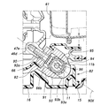
次に、後下部支持部82について説明する。図5及び図6に示すように、エンジン2のクランクケース46の底部の後側の隅部には、前方に向けて上方へ約40の傾斜角度をもって斜め内方に向けて形成された互いに平行な2本の有底のねじ孔46eが形成されており、これらのねじ孔46eに捩じ込まれる2本の締結ボルト90によって取付ブラケット91が固定される。2本の締結ボルト90は、クランクケース46の合わせ面46b(図4)に直交する互いに平行な軸線90Xを有している。即ち、ねじ孔46eもクランクケース46の下半部分46dを上半部分46cに締結するためのボルト52の挿通孔と同様に合わせ面46bに直交する。そのため、ねじ孔46eの加工が容易である。
取付ブラケット91は、これらの締結ボルト90を挿通させるための2つの貫通孔92aが形成された基部92と、基部92から後方斜め下方に延出し、シュラウド66の後下部に形成された開口66bから外部に突出する、左右に延在する軸線を有する取付孔93aを画定する2つの筒状部93とを有する。取付ブラケット91は、筒状部93がシュラウド66の開口66bの縁部を保持することでシュラウド66を支持している。2つの筒状部93は、締結ボルト90の軸線90X上に設けられた切欠93bによって分断されており、この切欠93bを除く基部92側の部分では互いに一体とされている。切欠93bは、締結ボルト90の挿通を許容し、且つ締結ボルト90を着脱する際に頭部に係合する工具のアクセスを許容する大きさとされている。即ち、2つの貫通孔92aは、基部92における、切欠93bに整合する2つの筒状部93の間の部分に設けられており、これにより取付ブラケット91の大型化が抑制される。これらの筒状部93には、左右1対の筒状のゴムブッシュ94がその軸方向の一部を挿入するように嵌合する。
ケース11の下部後側には、アンダーカバー16の後部上面から上方に突出する、マウント部をなす左右1対の取付リブ11bが形成されている。これら1対の取付リブ11bに設けられた支持孔11dに挿入されるカラー95は、支持孔11dに両端部を支持され、左右1対のワッシャ98に挟まれる前記の1対のゴムブッシュ94を中間部分の外周に支持する。右サイドカバー13に形成された取付ボス11aから挿入されてカラー95を貫通するマウントボルト96を、左サイドカバー12に形成された取付ボス11aに設けた埋設ナット97に締結することにより、シュラウド66から露出する取付ブラケット91がゴムブッシュ94を介してアンダーカバー16に弾性的に支持される。これにより、エンジン2の振動がケース11に伝わることが抑制される。また、ゴムブッシュ94の内側にカラー95が設けられ、カラー95にマウントボルト96が設けられるため、マウントボルト96の締め付けによってゴムブッシュ94がマウントボルト96に圧接することない。そのため、マウントボルト96を埋設ナット97に確実に締結することができる。
マウントボルト96及びマウントボルト96を外囲するカラー95は、水平方向(シリンダ47aの軸線を通る鉛直平面に直交する方向)に延在している。2つの筒状部93は、マウントボルト96及びカラー95の軸方向の中間部を外囲しており、マウントボルト96及びカラー95を介して取付ボス11aに取り付けられる。締結ボルト90の軸線90Xは、クランクケース46の合わせ面46b(図4)に直交し、且つカラー95及びマウントボルト96に直交している。従って、締結ボルト90の軸線方向から見たときに、カラー95及びマウントボルト96は、締結ボルト90に対して少なくとも部分的に重なり合う。そのため、締結ボルト90を介してエンジン2から取付ブラケット91に伝わる荷重がカラー95に直線的に伝わる。これにより、取付ブラケット91に作用する曲げモーメントが小さくなり、締結ボルト90及びねじ孔46eに作用する曲げモーメントも小さくなるため、後下部支持部82における支持剛性の低下が抑制される。
前下部支持部83について説明する。図4に示すように、ファンカバー71の下部には取付ブラケット71aが一体に形成されている。ケース11の下部前側には、アンダーカバー16の前部上面から上方に突出する、マウント部をなす左右1対の取付リブ11cが形成されている。取付ブラケット71aは左右1対の取付リブ11cにマウントボルト96及びゴムブッシュ94を介して弾性支持される。この取付ブラケット71aの支持構造は、取付ブラケット91の支持構造と実質的に同一である。
図4及び図5に示すように、使用者がエンジン発電機1を持ち運ぶべくキャリングハンドル17を持ち上げると、エンジン2及び発電機3を含む発電ユニット4の荷重の大部分は、ヘッドカバー51の支持板51cからゴムブッシュ85、連結ピン89及び取付ボス11aを経てケース11のキャリングハンドル17に支持される。即ち、発電ユニット4はキャリングハンドル17に直接吊り下げられる状態になり、ケース11自体により発電ユニット4の荷重を支持する必要がなくなる。これにより、キャリングハンドル17の下方に連なるケース11の肉厚を減少させて軽量化を図ることが可能になるだけでなく、ケース11の形状や材質の設計自由度が大幅に増加する。
図3に併せて示すように、発電ユニット4の下側前部を支持するアンダーカバー16の前部が高剛性の左右の補強フレーム26を介してキャリングハンドル17の前部に連結されているため、左サイドカバー12及び右サイドカバー13が荷重を負担することなくキャリングハンドル17が前後にて荷重を分散して支持する。そのため、ケース11におけるキャリングハンドル17近傍に生じる曲げ応力が軽減する。
一方、エンジン発電機1を地面或いは床面上に配置した状態では、発電ユニット4の荷重の大部分は支持脚21を備えたアンダーカバー16に直接伝達されるため、左サイドカバー12及び右サイドカバー13の剛性が低く設定されても荷重による変形が発生することがない。
また、発電ユニット4は、上部支持部81、後下部支持部82及び前下部支持部83の3箇所にてケース11に弾性支持されるため、発電ユニット4の荷重はケース11の各部に分散する。しかもゴムブッシュ85、94、94の振動吸収作用により、エンジン2のキャリングハンドル17への振動伝達が抑制されるだけでなく、エンジン2の振動によるケース11の共振が防止される。
エンジン発電機1を地面或いは床面上に配置した状態では、4本のボルト29、96を外すだけで、左サイドカバー12及び右サイドカバー13をアンダーカバー16から分離することができるので、エンジン発電機1を横倒しにしたりせずに、エンジン2や発電機3を露出させて容易にメンテナンスすることができる。
本実施形態のエンジン発電機1では、取付ブラケット91をクランクケース46に締結する締結ボルト90が、取付ブラケット91の貫通孔92aに挿通され、且つクランクケース46の底部の隅部に斜め内方に向けて形成されたねじ孔46eに捩じ込まれるため、後下部支持部82の支持剛性を低下させることなくケース11内の空間を広くすることができる。即ち、図6に想像線で示すように、取付ブラケット91が後方へ水平に突出している場合には、取付ブラケット91の位置が相対的に高く、その上方の空間が比較的小さい。これに対し、上記の構成によって取付ブラケット91が下側にずれることにより、この分だけケース11内の空間が広くなる。従って、ケース11内にて取付ブラケット91の上側に配置されたマフラー61をその分だけ大型化することができる。これにより、マフラー61の消音効果を低下させることなく排気触媒62を大型化して排気浄化性能を高めることが可能になる。
以上で具体的実施形態の説明を終えるが、本発明は上記実施形態に限定されることなく幅広く変形実施することができる。例えば、上記実施形態では、一例としてエンジン発電機1に本発明を適用したが、エンジンポンプや建設機械等の他のエンジン作業機に本発明を適用してもよく、別体の作業機を駆動するためのエンジンを備えるエンジン装置に本発明を適用してもよい。また、各部材や部位の具体的構成や配置、数量、角度など、本発明の趣旨を逸脱しない範囲であれば適宜変更可能である。一方、上記実施形態に示した各構成要素は必ずしも全てが必須ではなく、適宜選択することができる。
1 エンジン発電機(エンジン装置)
2 エンジン
3 発電機(作業機)
4 発電ユニット
11 ケース
11b 取付リブ(マウント部)
11d 支持孔
45 クランクシャフト
46 クランクケース
46b 合わせ面
46c 上半部分(第1半体)
46d 下半部分(第2半体)
46e ねじ孔
61 マフラー
62 排気触媒
81 上部支持部
82 後下部支持部
83 前下部支持部
90 締結ボルト
90X 軸線
91 取付ブラケット
92 基部
92a 貫通孔
93 筒状部
93a 取付孔
94 ゴムブッシュ
95 カラー(マウント軸部材)
96 マウントボルト(マウント軸部材)
2 エンジン
3 発電機(作業機)
4 発電ユニット
11 ケース
11b 取付リブ(マウント部)
11d 支持孔
45 クランクシャフト
46 クランクケース
46b 合わせ面
46c 上半部分(第1半体)
46d 下半部分(第2半体)
46e ねじ孔
61 マフラー
62 排気触媒
81 上部支持部
82 後下部支持部
83 前下部支持部
90 締結ボルト
90X 軸線
91 取付ブラケット
92 基部
92a 貫通孔
93 筒状部
93a 取付孔
94 ゴムブッシュ
95 カラー(マウント軸部材)
96 マウントボルト(マウント軸部材)
Claims (7)
- エンジン及び前記エンジンを収容するケースを備えたエンジン装置であって、
前記エンジンは、当該エンジンの下側部分を構成するクランクケースを含み、且つ複数の支持部を介して前記ケースに取り付けられ、
前記支持部の少なくとも1つが、前記ケースに設けられたマウント部と、前記クランクケースの底部に締結ボルトにより締結され、且つ前記マウント部に取り付けられた取付ブラケットとを有し、
前記締結ボルトが、前記取付ブラケットに設けられた貫通孔に挿通され、且つ前記クランクケースの前記底部の隅部に斜め内方に向けて形成されたねじ孔に捩じ込まれていることを特徴とするエンジン装置。 - 前記クランクケースがクランク軸線に対して斜めの合わせ面をもって複数のボルトにより互いに結合された、第1半体と前記ねじ孔を備える第2半体とを有し、前記ねじ孔が前記合わせ面に直交することを特徴とする請求項1に記載のエンジン装置。
- 前記取付ブラケットは、前記取付ブラケットに設けられた取付孔及び前記マウント部に設けられた支持孔に水平方向に挿通されたマウント軸部材を介して、前記マウント部に取り付けられ、前記締結ボルトの軸線方向から見たときに、前記マウント軸部材が、前記締結ボルトに対して少なくとも部分的に重なり合うことを特徴とする請求項2に記載のエンジン装置。
- 前記マウント部が、前記マウント軸部材の2つの端部のそれぞれについて設けられ、
前記取付ブラケットは、前記マウント軸部材の前記2つの端部間の中間部分を外囲する2つの筒状部を含み、前記筒状部が、前記マウント軸部材の外周及び前記筒状部の内周間に配置されたゴムブッシュを介して前記マウント軸部材に支持されていることを特徴とする請求項3に記載のエンジン装置。 - 前記貫通孔が、前記取付ブラケットの前記両筒状部の間の部分に設けられていることを特徴とする請求項4に記載のエンジン装置。
- 前記マウント軸部材が、マウントボルト及び前記マウントボルトを外囲するカラーを含むことを特徴とする請求項4に記載のエンジン装置。
- 前記エンジンの前記取付ブラケットが取り付けられた側と前記ケースとの間に画定される空間に配置され、且つ排気触媒を内蔵するマフラーを更に備えることを特徴とする請求項1~請求項5のいずれかに記載のエンジン装置。
Priority Applications (5)
| Application Number | Priority Date | Filing Date | Title |
|---|---|---|---|
| PCT/JP2017/044444 WO2019116434A1 (ja) | 2017-12-11 | 2017-12-11 | エンジン装置 |
| JP2019559437A JP6773921B2 (ja) | 2017-12-11 | 2017-12-11 | エンジン装置 |
| EP17934924.6A EP3693569B1 (en) | 2017-12-11 | 2017-12-11 | Engine device |
| CN201780097356.3A CN111433444B (zh) | 2017-12-11 | 2017-12-11 | 发动机装置 |
| US16/758,931 US11143139B2 (en) | 2017-12-11 | 2017-12-11 | Engine device |
Applications Claiming Priority (1)
| Application Number | Priority Date | Filing Date | Title |
|---|---|---|---|
| PCT/JP2017/044444 WO2019116434A1 (ja) | 2017-12-11 | 2017-12-11 | エンジン装置 |
Publications (1)
| Publication Number | Publication Date |
|---|---|
| WO2019116434A1 true WO2019116434A1 (ja) | 2019-06-20 |
Family
ID=66819053
Family Applications (1)
| Application Number | Title | Priority Date | Filing Date |
|---|---|---|---|
| PCT/JP2017/044444 Ceased WO2019116434A1 (ja) | 2017-12-11 | 2017-12-11 | エンジン装置 |
Country Status (5)
| Country | Link |
|---|---|
| US (1) | US11143139B2 (ja) |
| EP (1) | EP3693569B1 (ja) |
| JP (1) | JP6773921B2 (ja) |
| CN (1) | CN111433444B (ja) |
| WO (1) | WO2019116434A1 (ja) |
Families Citing this family (2)
| Publication number | Priority date | Publication date | Assignee | Title |
|---|---|---|---|---|
| CN113357039B (zh) * | 2021-07-19 | 2022-06-03 | 赣州市领沃电子科技有限公司 | 一种可拆卸式发动机线束塑壳保护外壳 |
| US11732634B1 (en) * | 2022-05-25 | 2023-08-22 | Kawasaki Motors, Ltd. | Engine |
Citations (8)
| Publication number | Priority date | Publication date | Assignee | Title |
|---|---|---|---|---|
| JPH017919Y2 (ja) * | 1984-07-31 | 1989-03-02 | ||
| JPH10121959A (ja) * | 1996-10-15 | 1998-05-12 | Yamaha Motor Co Ltd | 多気筒内燃機関の水冷却装置 |
| JP2001027127A (ja) | 1999-07-12 | 2001-01-30 | Honda Motor Co Ltd | エンジン作業機 |
| JP3340665B2 (ja) * | 1998-01-19 | 2002-11-05 | 本田技研工業株式会社 | エンジン作業機 |
| JP3871829B2 (ja) * | 1999-07-12 | 2007-01-24 | 本田技研工業株式会社 | エンジン発電機 |
| JP2017160833A (ja) * | 2016-03-09 | 2017-09-14 | 本田技研工業株式会社 | オーバーヘッドカムシャフト式エンジン |
| JP2017166400A (ja) * | 2016-03-16 | 2017-09-21 | 本田技研工業株式会社 | エンジン駆動作業機 |
| JP2017166397A (ja) * | 2016-03-15 | 2017-09-21 | 本田技研工業株式会社 | エンジン駆動作業機 |
Family Cites Families (12)
| Publication number | Priority date | Publication date | Assignee | Title |
|---|---|---|---|---|
| US2287399A (en) * | 1939-12-23 | 1942-06-23 | Packard Motor Car Co | Internal combustion engine |
| JPS6140425A (ja) * | 1984-07-31 | 1986-02-26 | Yanmar Diesel Engine Co Ltd | ケ−ス収容型エンジン発電機 |
| US4729353A (en) * | 1986-12-29 | 1988-03-08 | Engineered Air Systems, Inc. | Fuel container support system for a combustion engine |
| DE4413255A1 (de) * | 1994-04-16 | 1995-10-19 | Bayerische Motoren Werke Ag | Verfahren zum Bruchtrennen des Lagerdeckels einer mehrteiligen Lageranordnung, insbesondere in Kurbelgehäusen von Brennkraftmaschinen |
| JP3418079B2 (ja) * | 1997-01-24 | 2003-06-16 | 澤藤電機株式会社 | 発動発電機 |
| JP3347044B2 (ja) * | 1998-01-19 | 2002-11-20 | 本田技研工業株式会社 | 携帯用エンジン作業機 |
| JP3886002B2 (ja) * | 2002-03-27 | 2007-02-28 | ヤマハ発動機株式会社 | エンジン発電機 |
| CN100427746C (zh) * | 2006-09-30 | 2008-10-22 | 无锡开普动力有限公司 | 四冲程发动机 |
| JP4475327B2 (ja) * | 2007-12-21 | 2010-06-09 | トヨタ自動車株式会社 | ブラケットの締結構造 |
| CN103016138A (zh) * | 2012-11-07 | 2013-04-03 | 沈阳航天三菱汽车发动机制造有限公司 | 涡轮增压发动机 |
| JP6839923B2 (ja) * | 2016-03-11 | 2021-03-10 | 三菱重工サーマルシステムズ株式会社 | 車載装置および電動圧縮機 |
| CN205663509U (zh) * | 2016-06-03 | 2016-10-26 | 韩群山 | 增程式电混发电机与发动机曲轴联接装置 |
-
2017
- 2017-12-11 EP EP17934924.6A patent/EP3693569B1/en active Active
- 2017-12-11 JP JP2019559437A patent/JP6773921B2/ja active Active
- 2017-12-11 WO PCT/JP2017/044444 patent/WO2019116434A1/ja not_active Ceased
- 2017-12-11 US US16/758,931 patent/US11143139B2/en active Active
- 2017-12-11 CN CN201780097356.3A patent/CN111433444B/zh not_active Expired - Fee Related
Patent Citations (8)
| Publication number | Priority date | Publication date | Assignee | Title |
|---|---|---|---|---|
| JPH017919Y2 (ja) * | 1984-07-31 | 1989-03-02 | ||
| JPH10121959A (ja) * | 1996-10-15 | 1998-05-12 | Yamaha Motor Co Ltd | 多気筒内燃機関の水冷却装置 |
| JP3340665B2 (ja) * | 1998-01-19 | 2002-11-05 | 本田技研工業株式会社 | エンジン作業機 |
| JP2001027127A (ja) | 1999-07-12 | 2001-01-30 | Honda Motor Co Ltd | エンジン作業機 |
| JP3871829B2 (ja) * | 1999-07-12 | 2007-01-24 | 本田技研工業株式会社 | エンジン発電機 |
| JP2017160833A (ja) * | 2016-03-09 | 2017-09-14 | 本田技研工業株式会社 | オーバーヘッドカムシャフト式エンジン |
| JP2017166397A (ja) * | 2016-03-15 | 2017-09-21 | 本田技研工業株式会社 | エンジン駆動作業機 |
| JP2017166400A (ja) * | 2016-03-16 | 2017-09-21 | 本田技研工業株式会社 | エンジン駆動作業機 |
Non-Patent Citations (1)
| Title |
|---|
| See also references of EP3693569A4 |
Also Published As
| Publication number | Publication date |
|---|---|
| EP3693569A1 (en) | 2020-08-12 |
| JP6773921B2 (ja) | 2020-10-21 |
| CN111433444A (zh) | 2020-07-17 |
| US11143139B2 (en) | 2021-10-12 |
| EP3693569B1 (en) | 2022-04-20 |
| JPWO2019116434A1 (ja) | 2020-07-16 |
| EP3693569A4 (en) | 2020-10-28 |
| CN111433444B (zh) | 2021-09-03 |
| US20200309062A1 (en) | 2020-10-01 |
Similar Documents
| Publication | Publication Date | Title |
|---|---|---|
| KR100394383B1 (ko) | 엔진 발전기 | |
| CN100504051C (zh) | 发动机驱动装置 | |
| JP4210571B2 (ja) | エンジン駆動式作業機 | |
| CN101066702B (zh) | 船外机 | |
| JP6773921B2 (ja) | エンジン装置 | |
| JP4145912B2 (ja) | エンジン作業機 | |
| JP4359265B2 (ja) | 汎用エンジンのマフラカバー構造 | |
| JP3585773B2 (ja) | エンジン発電機 | |
| JP3754697B2 (ja) | エンジン作業機 | |
| JP2001027126A (ja) | エンジン発電機 | |
| JP4145911B2 (ja) | エンジン作業機 | |
| JP2722089B2 (ja) | エンジン作業機組立体 | |
| JPH11334389A (ja) | 傾斜単気筒水冷式内燃機関 | |
| JP2665677B2 (ja) | エンジン作業機組立体 | |
| JP2004353677A5 (ja) | ||
| JP2005282581A (ja) | エンジン作業機 | |
| JPH0264226A (ja) | 携帯形電源装置 |
Legal Events
| Date | Code | Title | Description |
|---|---|---|---|
| 121 | Ep: the epo has been informed by wipo that ep was designated in this application |
Ref document number: 17934924 Country of ref document: EP Kind code of ref document: A1 |
|
| ENP | Entry into the national phase |
Ref document number: 2019559437 Country of ref document: JP Kind code of ref document: A |
|
| ENP | Entry into the national phase |
Ref document number: 2017934924 Country of ref document: EP Effective date: 20200505 |
|
| NENP | Non-entry into the national phase |
Ref country code: DE |