WO2019116819A1 - Module de batterie - Google Patents
Module de batterie Download PDFInfo
- Publication number
- WO2019116819A1 WO2019116819A1 PCT/JP2018/042352 JP2018042352W WO2019116819A1 WO 2019116819 A1 WO2019116819 A1 WO 2019116819A1 JP 2018042352 W JP2018042352 W JP 2018042352W WO 2019116819 A1 WO2019116819 A1 WO 2019116819A1
- Authority
- WO
- WIPO (PCT)
- Prior art keywords
- battery
- circuit board
- battery module
- pedestal
- multilayer circuit
- Prior art date
- Legal status (The legal status is an assumption and is not a legal conclusion. Google has not performed a legal analysis and makes no representation as to the accuracy of the status listed.)
- Ceased
Links
Images




Classifications
-
- H—ELECTRICITY
- H01—ELECTRIC ELEMENTS
- H01M—PROCESSES OR MEANS, e.g. BATTERIES, FOR THE DIRECT CONVERSION OF CHEMICAL ENERGY INTO ELECTRICAL ENERGY
- H01M50/00—Constructional details or processes of manufacture of the non-active parts of electrochemical cells other than fuel cells, e.g. hybrid cells
- H01M50/20—Mountings; Secondary casings or frames; Racks, modules or packs; Suspension devices; Shock absorbers; Transport or carrying devices; Holders
- H01M50/204—Racks, modules or packs for multiple batteries or multiple cells
- H01M50/207—Racks, modules or packs for multiple batteries or multiple cells characterised by their shape
- H01M50/216—Racks, modules or packs for multiple batteries or multiple cells characterised by their shape adapted for button or coin cells
-
- H—ELECTRICITY
- H01—ELECTRIC ELEMENTS
- H01M—PROCESSES OR MEANS, e.g. BATTERIES, FOR THE DIRECT CONVERSION OF CHEMICAL ENERGY INTO ELECTRICAL ENERGY
- H01M10/00—Secondary cells; Manufacture thereof
- H01M10/42—Methods or arrangements for servicing or maintenance of secondary cells or secondary half-cells
- H01M10/425—Structural combination with electronic components, e.g. electronic circuits integrated to the outside of the casing
-
- H—ELECTRICITY
- H01—ELECTRIC ELEMENTS
- H01M—PROCESSES OR MEANS, e.g. BATTERIES, FOR THE DIRECT CONVERSION OF CHEMICAL ENERGY INTO ELECTRICAL ENERGY
- H01M50/00—Constructional details or processes of manufacture of the non-active parts of electrochemical cells other than fuel cells, e.g. hybrid cells
- H01M50/20—Mountings; Secondary casings or frames; Racks, modules or packs; Suspension devices; Shock absorbers; Transport or carrying devices; Holders
- H01M50/202—Casings or frames around the primary casing of a single cell or a single battery
-
- H—ELECTRICITY
- H01—ELECTRIC ELEMENTS
- H01M—PROCESSES OR MEANS, e.g. BATTERIES, FOR THE DIRECT CONVERSION OF CHEMICAL ENERGY INTO ELECTRICAL ENERGY
- H01M50/00—Constructional details or processes of manufacture of the non-active parts of electrochemical cells other than fuel cells, e.g. hybrid cells
- H01M50/20—Mountings; Secondary casings or frames; Racks, modules or packs; Suspension devices; Shock absorbers; Transport or carrying devices; Holders
- H01M50/233—Mountings; Secondary casings or frames; Racks, modules or packs; Suspension devices; Shock absorbers; Transport or carrying devices; Holders characterised by physical properties of casings or racks, e.g. dimensions
- H01M50/242—Mountings; Secondary casings or frames; Racks, modules or packs; Suspension devices; Shock absorbers; Transport or carrying devices; Holders characterised by physical properties of casings or racks, e.g. dimensions adapted for protecting batteries against vibrations, collision impact or swelling
-
- H—ELECTRICITY
- H01—ELECTRIC ELEMENTS
- H01M—PROCESSES OR MEANS, e.g. BATTERIES, FOR THE DIRECT CONVERSION OF CHEMICAL ENERGY INTO ELECTRICAL ENERGY
- H01M50/00—Constructional details or processes of manufacture of the non-active parts of electrochemical cells other than fuel cells, e.g. hybrid cells
- H01M50/20—Mountings; Secondary casings or frames; Racks, modules or packs; Suspension devices; Shock absorbers; Transport or carrying devices; Holders
- H01M50/284—Mountings; Secondary casings or frames; Racks, modules or packs; Suspension devices; Shock absorbers; Transport or carrying devices; Holders with incorporated circuit boards, e.g. printed circuit boards [PCB]
-
- H—ELECTRICITY
- H01—ELECTRIC ELEMENTS
- H01M—PROCESSES OR MEANS, e.g. BATTERIES, FOR THE DIRECT CONVERSION OF CHEMICAL ENERGY INTO ELECTRICAL ENERGY
- H01M2220/00—Batteries for particular applications
- H01M2220/30—Batteries in portable systems, e.g. mobile phone, laptop
-
- Y—GENERAL TAGGING OF NEW TECHNOLOGICAL DEVELOPMENTS; GENERAL TAGGING OF CROSS-SECTIONAL TECHNOLOGIES SPANNING OVER SEVERAL SECTIONS OF THE IPC; TECHNICAL SUBJECTS COVERED BY FORMER USPC CROSS-REFERENCE ART COLLECTIONS [XRACs] AND DIGESTS
- Y02—TECHNOLOGIES OR APPLICATIONS FOR MITIGATION OR ADAPTATION AGAINST CLIMATE CHANGE
- Y02E—REDUCTION OF GREENHOUSE GAS [GHG] EMISSIONS, RELATED TO ENERGY GENERATION, TRANSMISSION OR DISTRIBUTION
- Y02E60/00—Enabling technologies; Technologies with a potential or indirect contribution to GHG emissions mitigation
- Y02E60/10—Energy storage using batteries
Definitions
- the present invention relates to a battery holding structure, and more particularly to a battery module structure in which a battery is mounted on a circuit board.
- a battery module in which a flat battery called coin shape or button shape is mounted on the surface of a multilayer circuit board is often used. Many mount a battery along with other electronic components on a mounting surface formed on the surface of a multilayer circuit board to form a predetermined circuit.
- the battery may be directly mounted on the surface of the multilayer circuit board using an electrode plate connected to each of the positive and negative electrodes of the battery.
- the present invention has been made in view of such a situation, and an object of the present invention is to provide a multilayer circuit in which a battery supplying power to a circuit board avoids a defect due to breakage of an electrode plate or dropping of a battery.
- An object of the present invention is to provide a battery module excellent in impact resistance mounted on a substrate.
- a battery module includes a case including a flat plate portion and a pedestal portion projecting from the flat plate portion, a circuit board having through holes through which the pedestal portion is inserted and formed in a thickness direction And a battery installed and held in the battery.
- the present invention it is possible to provide a battery module excellent in impact resistance in which a battery for supplying power to a circuit board is mounted on the circuit board while avoiding a defect due to breakage of the electrode plate or dropping of the battery. it can.
- the perspective view which shows the external appearance of the battery module which concerns on the Example of this invention The perspective view which decomposed
- FIG. 1 shows the overall appearance of the battery module
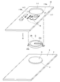
- FIG. 2 shows an exploded view of the main part of the battery module
- FIG. 3 shows a cross section of the battery module (viewed along the line AA 'in FIG. 1).
- FIG. 4 shows a cross section of the multilayer circuit board (in the direction of the arrows B--B 'in FIG. 2).
- the battery module 1 is comprised by the housing
- the multilayer circuit board 10 may be a single layer circuit board in which the conductive layer is a single layer.
- the housing 2 includes a flat plate portion 3 and includes a pedestal portion 4 projecting upward from the flat plate portion 3, and an upper portion of the pedestal portion 4 is an upper surface 5 which is a substantially flat surface.
- a plurality of electronic components 16 for forming a battery module are disposed on the surface side of multilayer circuit board 10, and a through hole 11 through which pedestal 4 of housing 2 is inserted is formed penetrating in the thickness direction .
- a pad accommodating portion 17 slightly recessed from the surface in the thickness direction is provided, and in the pad accommodating portion 17, pad portions 18a and 18b (in FIG. 4). ) Is provided.
- electrode plates 22a and 22b are attached to positive and negative electrodes, respectively.
- the electrode plate 22 a is connected to one of positive and negative electrodes provided on one surface of the battery 20 and extends until it protrudes to the side of the battery 20. Furthermore, it bends at a portion that protrudes laterally, extends toward the other surface opposite to one surface of the battery 20, and bends again laterally outward of the battery 20 on substantially the same plane as the other surface of the battery 20. Then, a connection portion to the pad portion 18a is formed.
- the electrode plate 22b is connected to the other electrode provided on the other surface of the battery 20, extends until it protrudes to the side of the battery 20, and forms a connecting portion to the pad portion 18b.
- the connection portion to the pad portion 18a of the electrode plate 22a and the connection portion to the pad portion 18b of the electrode plate 22b are formed at positions where connection is possible on the same plane.
- a lid 30 is provided on the housing 2 so as to cover the multilayer circuit board 10 and the battery 20. That is, the housing 2 and the lid 30 cooperate to form a space for housing the battery 20, and the battery 20 is disposed in the sealed space.
- the multilayer circuit board 10 is a surface of the multilayer circuit board 10 on which the plurality of electronic components 16 are disposed, with the pedestal 4 of the housing 2 inserted through the through hole 11.
- the reverse surface on the opposite side is fixed and installed on the flat plate portion 3 of the housing 2.
- the pedestal 4 since the thickness of the pedestal 4 is larger than the thickness of the multilayer circuit board 10, the pedestal 4 penetrates the through holes 11 of the multilayer circuit board 10, and the pedestal 4 is multilayer It projects further upward from the surface of the circuit board 10.
- the battery 20 is installed and held on the upper surface 5 of the pedestal portion 4 in a state where the pedestal portion 4 protrudes further upward from the surface of the multilayer circuit board 10. More preferably, the battery 20 is fixed to the upper surface 5 with an adhesive material such as an adhesive. In addition, since the upper surface 5 protrudes upward from the surface of the multilayer circuit board 10, the battery 20 is the multilayer circuit board 10 even if the outer dimension of the upper surface 5 of the pedestal 4 is smaller than the outer dimension of the battery 20. It can be installed to avoid direct contact with the
- the area of the upper surface 5 of the pedestal 4 is sufficient as long as the battery 20 can be fixed to the upper surface 5 to support its weight. Therefore, the size of the opening of the through hole 11 through which the pedestal 4 is inserted It can be made smaller. Thus, the area of the multilayer circuit board 10 can be reduced, and the mechanical strength of the multilayer circuit board 10 can be improved.
- connection parts of the electrode plates 22a and 22b for connecting the battery 20 to the multilayer circuit board 10 are formed to be connectable on the same plane. Therefore, the battery 20 can be installed on the upper surface 5 of the pedestal 4 so that the electrode plates 22a and 22b contact the pad portions 18a and 18b on the surface of the multilayer circuit board 10, respectively.
- the battery 20 is adhered and fixed to the pedestal portion 4 of the housing 2, all the weight is supported by the housing 2, and the battery does not fall off. In addition, stress due to the weight of the battery 20 is not applied to the multilayer circuit board 10 or the electrode plates 22a and 22b. Thus, damage to the multilayer circuit board 10 and the electrode plates 22a and 22b is suppressed.
- the multilayer circuit board 10 is fixedly installed on the flat plate portion 3 of the housing 2, even if the multilayer circuit board 10 is reduced in thickness and mechanical strength is reduced, its shape is Since no deformation occurs, no stress is applied from the multilayer circuit board 10 to the electrode plates 22a and 22b. Therefore, if the electrode plates 22a and 22b have the strength to support the weight of the electrode plate itself, the electrode plates 22a and 22b themselves are not damaged by external impact to the battery module 1, and the electric conduction is not impaired. .
- the present invention prevents the breakage of the electrode plates 22 a and 22 b and the detachment of the battery 20 of the battery 20 mounted on the multilayer circuit board 10 to supply power. As a result, it is possible to obtain the unique effect of providing the battery module 1 having excellent impact resistance capable of avoiding the loss of the power supply function due to the impact from the outside of the module.
- the through hole 11 of the multilayer circuit board 10 is smaller than the battery 20
- the thickness of the pedestal 4 of the housing 2 is thicker than the thickness of the multilayer circuit board 10
- the pedestal 4 is a multilayer circuit It is a structure which protrudes above the surface of the substrate 10.
- the thickness of the multilayer circuit board 10 constituting the battery module 1 and the outer shape of the battery 20.
- FIG. 5 shows the overall appearance of the battery module
- FIG. 6 shows an exploded view of the main part of the battery module
- FIG. 7 shows a cross section of the battery module (viewed along C-C 'in FIG. 5).
- FIG. 8 shows a cross section of the multilayer circuit board (viewed in the direction of arrows DD in FIG. 5). The description of the same parts as those of the above-described embodiment will be omitted.
- a through hole 111 penetrating in the thickness direction is provided in the multilayer circuit board 10.
- a pad housing portion 117 recessed from the back surface in the thickness direction is provided on the back surface of the multilayer circuit board 10 in the peripheral portion of the through hole 11, and pad portions 118 a and 118 b are provided in the pad housing portion 117. It is done.
- the multilayer circuit board 10 is fixed on the flat plate portion 3 of the housing 2 with a spacer 12 at a position where the base portion 4 of the housing 2 can be inserted into the through hole 111.
- a space is formed between the multilayer circuit board 10 and the flat plate portion 3 of the housing 2, and the upper surface 5 of the pedestal portion 4 is from the surface of the multilayer circuit board 10 It is in a recessed position.
- the battery 20 is installed on the upper surface 5 of the pedestal 4 in a state where the pedestal 4 is recessed from the surface of the multilayer circuit board 10. More preferably, the battery 20 is fixed to the upper surface 5 with an adhesive material such as an adhesive. Further, since the upper surface 5 of the pedestal 4 is recessed from the surface of the multilayer circuit board 10, the size of the opening size of the through hole 111 is the outer shape of the battery 20 so that the battery 20 does not contact the multilayer circuit board 10 directly. It needs to be larger than the dimensions.
- the upper surface 5 of the pedestal portion 4 may be inside the through hole 111 so that the battery 20 is disposed to occupy a part of the through hole 111 of the multilayer circuit board 10. Further, the height of the pedestal 4 is lowered so that the battery 20 occupies the entire through hole 111, and the upper surface 5 of the pedestal 4 is below the back surface of the multilayer circuit board 10, ie, penetrates It may be outside the hole 111.
- the shapes of the electrode plates 22a and 22b connected to the positive and negative electrodes of the battery 20 are formed such that the connection portions of the electrode plates to the pad portions 118a and 118b can be connected on the same plane. Therefore, the battery 20 can be placed on the upper surface 5 of the pedestal 4 so that the electrode plates 22 a and 22 b are in contact with the pad portions 118 a and 118 b on the back surface of the multilayer circuit board 10.
- the thickness of the battery module 1 is at least greater than the sum of the thickness of the housing 2, the thickness of the multilayer circuit board 10, and the thickness of the battery 20 including the electrode plates 22a and 22b 3 and 4).
- the present modification it does not depend on the thickness of the multilayer circuit board 10, but only on the thickness of the housing 2 and the thickness of the battery 20 including the electrode plates 22a and 22b (see FIGS. 7 and 8) It is advantageous to lower the height.
- the present invention can be variously modified to configure the more optimal battery module 1.
- the multilayer circuit board 10 and the battery 20 are both fixed to and supported by the upper surface 5 of the flat plate portion 3 and the pedestal portion 4 of the housing 2.
- this modification prevents the breakage of the electrode plates 22a and 22b and the detachment of the battery 20 of the battery 20 mounted on the multilayer circuit board 10 and supplying power.
- it is possible to obtain the unique effect of providing the battery module 1 having excellent impact resistance capable of avoiding the loss of the power supply function due to the impact from the outside of the module.
- a battery module includes a case including a flat plate portion and a pedestal portion projecting from the flat plate portion, a circuit board having through holes through which the pedestal portion is inserted and formed in a thickness direction And a battery installed and held in the battery.
- the pedestal portion of the housing inserted into the through hole of the circuit board penetrates the through hole and protrudes more than the flat portion of the circuit board .
- the opening dimension of the through hole of the circuit board is smaller than the outer dimension of the battery.
- the battery is fixed to the pedestal of the housing by an adhesive material.
- the opening dimension of the through hole of the circuit board is larger than the outer dimension of the battery.
- a part of the battery installed and held in the pedestal portion of the housing is disposed in the through hole of the circuit board.
Landscapes
- Chemical & Material Sciences (AREA)
- Chemical Kinetics & Catalysis (AREA)
- Electrochemistry (AREA)
- General Chemical & Material Sciences (AREA)
- Engineering & Computer Science (AREA)
- Microelectronics & Electronic Packaging (AREA)
- Manufacturing & Machinery (AREA)
- Battery Mounting, Suspending (AREA)
Abstract
L'invention concerne un module de batterie comprenant : un boîtier qui comprend une partie plaque plate et une partie socle qui fait saillie à partir de la partie plaque plate ; une carte de circuit imprimé qui comprend un trou traversant, dans laquelle la partie socle est insérée, dans la direction de l'épaisseur, tout en étant fixée au boîtier ; et une batterie qui est fixée à la partie socle. La batterie est une batterie plate qui a une forme de pièce ou une forme de bouton. Des plaques d'électrode, qui sont respectivement connectées à l'électrode positive et à l'électrode négative de la batterie, sont connectées à la carte de circuit imprimé de façon à fournir une puissance à un composant électronique qui est agencé sur la carte de circuit imprimé.
Priority Applications (4)
| Application Number | Priority Date | Filing Date | Title |
|---|---|---|---|
| EP18889409.1A EP3726608B1 (fr) | 2017-12-13 | 2018-11-15 | Module de batterie |
| CN201880080918.8A CN111480247B (zh) | 2017-12-13 | 2018-11-15 | 电池模块 |
| KR1020207016786A KR102488292B1 (ko) | 2017-12-13 | 2018-11-15 | 전지 모듈 |
| US16/770,520 US11742545B2 (en) | 2017-12-13 | 2018-11-15 | Battery module |
Applications Claiming Priority (2)
| Application Number | Priority Date | Filing Date | Title |
|---|---|---|---|
| JP2017-238731 | 2017-12-13 | ||
| JP2017238731A JP6978920B2 (ja) | 2017-12-13 | 2017-12-13 | 電池モジュール |
Publications (1)
| Publication Number | Publication Date |
|---|---|
| WO2019116819A1 true WO2019116819A1 (fr) | 2019-06-20 |
Family
ID=66820285
Family Applications (1)
| Application Number | Title | Priority Date | Filing Date |
|---|---|---|---|
| PCT/JP2018/042352 Ceased WO2019116819A1 (fr) | 2017-12-13 | 2018-11-15 | Module de batterie |
Country Status (7)
| Country | Link |
|---|---|
| US (1) | US11742545B2 (fr) |
| EP (1) | EP3726608B1 (fr) |
| JP (1) | JP6978920B2 (fr) |
| KR (1) | KR102488292B1 (fr) |
| CN (1) | CN111480247B (fr) |
| TW (1) | TWI686986B (fr) |
| WO (1) | WO2019116819A1 (fr) |
Families Citing this family (2)
| Publication number | Priority date | Publication date | Assignee | Title |
|---|---|---|---|---|
| EP4016716B1 (fr) | 2020-12-21 | 2025-01-22 | Maximilian Weiland | Dispositif de montage pour une batterie composite |
| CN113315208A (zh) * | 2021-06-21 | 2021-08-27 | 深圳市迪比科电子科技有限公司 | 无风扇便携式储能电源 |
Citations (7)
| Publication number | Priority date | Publication date | Assignee | Title |
|---|---|---|---|---|
| JPS61169955U (fr) * | 1985-04-11 | 1986-10-21 | ||
| JPS61206261U (fr) * | 1985-06-17 | 1986-12-26 | ||
| JPH0386562U (fr) * | 1989-12-21 | 1991-09-02 | ||
| JP2007242629A (ja) | 2002-06-27 | 2007-09-20 | Hitachi Maxell Ltd | 端子板付き電池 |
| WO2008120455A1 (fr) * | 2007-03-14 | 2008-10-09 | Panasonic Corporation | Dispositif électrochimique avec bornes et structure de montage le comprenant |
| JP2014011049A (ja) * | 2012-06-29 | 2014-01-20 | Hitachi Maxell Ltd | 電池ユニット |
| JP2017183004A (ja) * | 2016-03-29 | 2017-10-05 | Fdk株式会社 | 電池モジュール |
Family Cites Families (18)
| Publication number | Priority date | Publication date | Assignee | Title |
|---|---|---|---|---|
| US3955124A (en) * | 1975-02-10 | 1976-05-04 | Air Products And Chemicals, Inc. | Removable coulometric timer connector assembly for printed circuit boards |
| JPS581971Y2 (ja) | 1977-01-10 | 1983-01-13 | 株式会社東芝 | 電源供給装置 |
| JPS5669771A (en) * | 1979-11-12 | 1981-06-11 | Canon Inc | Electronic equipment with battery-mounting mechanism |
| JPS61107658A (ja) * | 1984-10-31 | 1986-05-26 | Canon Inc | 電子機器 |
| JPH04144055A (ja) * | 1990-10-05 | 1992-05-18 | Mitsubishi Electric Corp | カード用モジユール |
| JPH05169885A (ja) | 1991-12-26 | 1993-07-09 | Mitsubishi Electric Corp | 薄型icカード |
| JPH0722012A (ja) * | 1993-06-29 | 1995-01-24 | Naldec Kk | 電源装置 |
| US5558679A (en) * | 1995-08-21 | 1996-09-24 | Micron Communications, Inc. | Method for mounting a battery on a substrate |
| JP3564207B2 (ja) * | 1995-08-31 | 2004-09-08 | セイコーエプソン株式会社 | 携帯用電子機器 |
| JPH09259852A (ja) | 1996-03-19 | 1997-10-03 | Toshiba Corp | 電池実装構造 |
| JPH10199499A (ja) * | 1997-01-13 | 1998-07-31 | Union Mach Kk | ボタン電池用ホルダ |
| JP2000149898A (ja) * | 1998-11-05 | 2000-05-30 | Oki Electric Ind Co Ltd | ボタン電池の取付構造 |
| JP2011192426A (ja) | 2010-03-12 | 2011-09-29 | Sanyo Electric Co Ltd | 電池収納部の構造 |
| DE102012106622A1 (de) | 2012-07-20 | 2014-01-23 | Huf Hülsbeck & Fürst Gmbh & Co. Kg | Flacher Kraftfahrzeugschlüssel |
| US9564774B2 (en) * | 2014-06-10 | 2017-02-07 | Pb Inc. | Reduced thickness tracking device |
| JP6187776B2 (ja) * | 2014-12-12 | 2017-08-30 | カシオ計算機株式会社 | 電子機器 |
| JP6657981B2 (ja) * | 2016-01-18 | 2020-03-04 | 日本精機株式会社 | 電子機器の電池収納構造 |
| JP6593228B2 (ja) * | 2016-03-09 | 2019-10-23 | セイコーエプソン株式会社 | 電子時計 |
-
2017
- 2017-12-13 JP JP2017238731A patent/JP6978920B2/ja active Active
-
2018
- 2018-11-15 KR KR1020207016786A patent/KR102488292B1/ko active Active
- 2018-11-15 WO PCT/JP2018/042352 patent/WO2019116819A1/fr not_active Ceased
- 2018-11-15 EP EP18889409.1A patent/EP3726608B1/fr active Active
- 2018-11-15 CN CN201880080918.8A patent/CN111480247B/zh active Active
- 2018-11-15 US US16/770,520 patent/US11742545B2/en active Active
- 2018-12-06 TW TW107143829A patent/TWI686986B/zh active
Patent Citations (7)
| Publication number | Priority date | Publication date | Assignee | Title |
|---|---|---|---|---|
| JPS61169955U (fr) * | 1985-04-11 | 1986-10-21 | ||
| JPS61206261U (fr) * | 1985-06-17 | 1986-12-26 | ||
| JPH0386562U (fr) * | 1989-12-21 | 1991-09-02 | ||
| JP2007242629A (ja) | 2002-06-27 | 2007-09-20 | Hitachi Maxell Ltd | 端子板付き電池 |
| WO2008120455A1 (fr) * | 2007-03-14 | 2008-10-09 | Panasonic Corporation | Dispositif électrochimique avec bornes et structure de montage le comprenant |
| JP2014011049A (ja) * | 2012-06-29 | 2014-01-20 | Hitachi Maxell Ltd | 電池ユニット |
| JP2017183004A (ja) * | 2016-03-29 | 2017-10-05 | Fdk株式会社 | 電池モジュール |
Also Published As
| Publication number | Publication date |
|---|---|
| CN111480247A (zh) | 2020-07-31 |
| EP3726608B1 (fr) | 2024-01-03 |
| JP2019106312A (ja) | 2019-06-27 |
| TWI686986B (zh) | 2020-03-01 |
| EP3726608A1 (fr) | 2020-10-21 |
| KR20200087204A (ko) | 2020-07-20 |
| JP6978920B2 (ja) | 2021-12-08 |
| TW201929293A (zh) | 2019-07-16 |
| CN111480247B (zh) | 2022-08-30 |
| KR102488292B1 (ko) | 2023-01-13 |
| US11742545B2 (en) | 2023-08-29 |
| EP3726608A4 (fr) | 2021-10-13 |
| US20200313125A1 (en) | 2020-10-01 |
Similar Documents
| Publication | Publication Date | Title |
|---|---|---|
| TWI650634B (zh) | 電子裝置、電子裝置電池及製造一電子裝置之方法 | |
| TWI629114B (zh) | 聲響產生裝置及電子設備 | |
| JP2016514281A (ja) | モバイル端末 | |
| CN109219307B (zh) | 散热结构及具有该散热结构的电子装置 | |
| WO2019116819A1 (fr) | Module de batterie | |
| US20090147456A1 (en) | Printed circuit board with multi layer ceramic capacitor and flat panel display device using the same | |
| CN100397174C (zh) | 液晶显示装置 | |
| US20160127824A1 (en) | Woofer speaker and the rear sound cavity forming method thereof | |
| CN204706588U (zh) | 压电变压器装置 | |
| CN103633261B (zh) | 电池组 | |
| JP6701352B2 (ja) | 電話カードを取り付けるためのカードホルダー装置及びモバイルデバイス | |
| CN201717838U (zh) | 压电振动器 | |
| JP2013255021A (ja) | 携帯端末装置及び携帯端末装置の組立方法 | |
| JP5615582B2 (ja) | El照明器具 | |
| JP6297203B2 (ja) | 防水空間内にアンテナが備えられた電子機器 | |
| WO2015033489A1 (fr) | Appareil d'affichage | |
| CN219999838U (zh) | 电子装置 | |
| TWI852085B (zh) | 多電池安裝結構及其電子器具 | |
| CN204466066U (zh) | 布线基材的载置治具 | |
| JP2017028206A (ja) | シールドケース | |
| JP3150907U (ja) | 液晶表示モジュールを備える電子装置 | |
| JP4844408B2 (ja) | 充電端子の取付構造 | |
| JP2014099789A (ja) | マイクおよびその実装構造 | |
| JP2017011022A (ja) | 回路モジュール | |
| JP2008192761A (ja) | シールド構造 |
Legal Events
| Date | Code | Title | Description |
|---|---|---|---|
| 121 | Ep: the epo has been informed by wipo that ep was designated in this application |
Ref document number: 18889409 Country of ref document: EP Kind code of ref document: A1 |
|
| ENP | Entry into the national phase |
Ref document number: 20207016786 Country of ref document: KR Kind code of ref document: A |
|
| NENP | Non-entry into the national phase |
Ref country code: DE |
|
| ENP | Entry into the national phase |
Ref document number: 2018889409 Country of ref document: EP Effective date: 20200713 |