WO2019142575A1 - Unité de ramification, dispositif de réfrigération et procédé d'installation de dispositif de réfrigération - Google Patents
Unité de ramification, dispositif de réfrigération et procédé d'installation de dispositif de réfrigération Download PDFInfo
- Publication number
- WO2019142575A1 WO2019142575A1 PCT/JP2018/046488 JP2018046488W WO2019142575A1 WO 2019142575 A1 WO2019142575 A1 WO 2019142575A1 JP 2018046488 W JP2018046488 W JP 2018046488W WO 2019142575 A1 WO2019142575 A1 WO 2019142575A1
- Authority
- WO
- WIPO (PCT)
- Prior art keywords
- pipe
- gas
- branch
- liquid
- liquid side
- Prior art date
- Legal status (The legal status is an assumption and is not a legal conclusion. Google has not performed a legal analysis and makes no representation as to the accuracy of the status listed.)
- Ceased
Links
Images





Classifications
-
- F—MECHANICAL ENGINEERING; LIGHTING; HEATING; WEAPONS; BLASTING
- F24—HEATING; RANGES; VENTILATING
- F24F—AIR-CONDITIONING; AIR-HUMIDIFICATION; VENTILATION; USE OF AIR CURRENTS FOR SCREENING
- F24F1/00—Room units for air-conditioning, e.g. separate or self-contained units or units receiving primary air from a central station
- F24F1/06—Separate outdoor units, e.g. outdoor unit to be linked to a separate room comprising a compressor and a heat exchanger
- F24F1/26—Refrigerant piping
- F24F1/32—Refrigerant piping for connecting the separate outdoor units to indoor units
-
- F—MECHANICAL ENGINEERING; LIGHTING; HEATING; WEAPONS; BLASTING
- F25—REFRIGERATION OR COOLING; COMBINED HEATING AND REFRIGERATION SYSTEMS; HEAT PUMP SYSTEMS; MANUFACTURE OR STORAGE OF ICE; LIQUEFACTION SOLIDIFICATION OF GASES
- F25B—REFRIGERATION MACHINES, PLANTS OR SYSTEMS; COMBINED HEATING AND REFRIGERATION SYSTEMS; HEAT PUMP SYSTEMS
- F25B41/00—Fluid-circulation arrangements
- F25B41/40—Fluid line arrangements
- F25B41/42—Arrangements for diverging or converging flows, e.g. branch lines or junctions
-
- F—MECHANICAL ENGINEERING; LIGHTING; HEATING; WEAPONS; BLASTING
- F16—ENGINEERING ELEMENTS AND UNITS; GENERAL MEASURES FOR PRODUCING AND MAINTAINING EFFECTIVE FUNCTIONING OF MACHINES OR INSTALLATIONS; THERMAL INSULATION IN GENERAL
- F16L—PIPES; JOINTS OR FITTINGS FOR PIPES; SUPPORTS FOR PIPES, CABLES OR PROTECTIVE TUBING; MEANS FOR THERMAL INSULATION IN GENERAL
- F16L19/00—Joints in which sealing surfaces are pressed together by means of a member, e.g. a swivel nut, screwed on, or into, one of the joint parts
- F16L19/08—Joints in which sealing surfaces are pressed together by means of a member, e.g. a swivel nut, screwed on, or into, one of the joint parts with metal rings which bite into the wall of the pipe
- F16L19/083—Joints in which sealing surfaces are pressed together by means of a member, e.g. a swivel nut, screwed on, or into, one of the joint parts with metal rings which bite into the wall of the pipe the longitudinal cross-section of the ring not being modified during clamping
- F16L19/086—Joints in which sealing surfaces are pressed together by means of a member, e.g. a swivel nut, screwed on, or into, one of the joint parts with metal rings which bite into the wall of the pipe the longitudinal cross-section of the ring not being modified during clamping with additional sealing means
-
- F—MECHANICAL ENGINEERING; LIGHTING; HEATING; WEAPONS; BLASTING
- F25—REFRIGERATION OR COOLING; COMBINED HEATING AND REFRIGERATION SYSTEMS; HEAT PUMP SYSTEMS; MANUFACTURE OR STORAGE OF ICE; LIQUEFACTION SOLIDIFICATION OF GASES
- F25B—REFRIGERATION MACHINES, PLANTS OR SYSTEMS; COMBINED HEATING AND REFRIGERATION SYSTEMS; HEAT PUMP SYSTEMS
- F25B2313/00—Compression machines, plants or systems with reversible cycle not otherwise provided for
- F25B2313/006—Compression machines, plants or systems with reversible cycle not otherwise provided for two pipes connecting the outdoor side to the indoor side with multiple indoor units
Definitions
- the present disclosure relates to a branching unit, a refrigeration apparatus including the branching unit, and a method of installing the refrigeration apparatus.
- Patent Document 1 discloses an air conditioner which is a type of refrigeration system.
- the air conditioner includes an outdoor unit, which is a heat source unit, and an indoor unit, which is a use side unit.
- one outdoor unit and a plurality of indoor units are connected by the liquid side communication pipe and the gas side communication pipe.
- Each of the liquid side communication pipe and the gas side communication pipe is provided with a branch header.
- the branch header is formed with one main flow port for connecting the outdoor unit and a plurality of branch flow ports for connecting the indoor unit.
- An object of the present disclosure is to simplify installation work of a refrigeration apparatus provided with a heat source unit and a use side unit.
- a first aspect of the present disclosure relates to a liquid side communication pipe (20) and a gas side communication pipe (25) that connect a heat source unit (11) of a refrigeration system (10) to a plurality of usage side units (12a to 12f). Targeted branch units to be provided. Then, one liquid side collecting port (52) provided in the liquid side communication pipe (20) for connecting the pipe (21) connected to the heat source unit (11), and the use side units (12a to 12f) And a plurality of liquid side branch ports (54a to 54f) for connecting pipes (22a to 22f) connected to each other, and one liquid side collecting port (52) is connected to all the liquid side branch ports (54a).
- the liquid side header (50) provided in the liquid side communication pipe (20) and the gas side header (60) provided in the gas side communication pipe (25) are accommodated in the casing (40). Unitized. Then, the branching unit (13) of the present embodiment in which the liquid side header (50) and the gas side header (60) are unitized is installed indoors together with the use side units (12a to 12f) of the refrigeration system (10). For this reason, compared with the case where the liquid side header (50) and the gas side header (60) are separately installed, the installation work of the refrigeration system (10) can be simplified.
- the liquid side collecting port (52) and the gas side collecting port (62) are provided at the first side surface (41) of the casing (40). It exposes to the exterior of the said casing (40).
- the liquid side collecting port (52) of the liquid side header (50) and the gas side collecting port (62) of the gas side header (60) form one side surface (41) of the casing (40). Exposed to the outside of the casing (40). Therefore, the operation of connecting the liquid side piping extending from the heat source unit (11) and the gas side piping to the branch unit (13) can be performed on the casing (40) from the same direction. Therefore, according to this aspect, the installation operation of the refrigeration system (10) can be further simplified.
- all the liquid side branch ports (54a to 54f) and all the gas side branch ports (64a to 64f) are included in the casing (40).
- the second side surface (42) is exposed to the outside of the casing (40).
- the liquid side branch ports (54a to 54f) and the gas side branch ports (64a to 64f) have the liquid side collecting port (52) and the gas side collecting port (62).
- the side surface (42) other than the exposed side surface (41) is exposed to the outside of the casing (40). For this reason, it is possible to easily secure the installation space of the pipe connecting the heat source unit (11) to the branch unit (13) and the pipe connecting the use side units (12a to 12f) to the branch unit (13) It becomes.
- the pair of liquid side branch ports (54a to 54f) and the gas side branch port (64a) are connected to the same use side unit (12a to 12f). -64f) are arranged vertically.
- the pair of liquid side branch ports (54a to 54f) and the gas side branch ports (64a to 64f) are disposed side by side vertically. For this reason, it is possible to easily identify the connection point of the pipe extending from the use side unit (12a to 12f) to the branch unit (13), and the installation work of the refrigeration system (10) can be further simplified.
- the liquid side header (50) is closed at one end and the other end is the liquid side collecting port (52) A liquid-side collecting pipe (51), and a plurality of liquid-side branch pipes (53a to 53f) protruding laterally from the liquid-side collecting pipe (51) and whose tips are the liquid-side branch ports (54a to 54f) , And the plurality of liquid side branch pipes (53a to 53f) are arranged at predetermined intervals in the axial direction of the liquid side collecting pipe (51), and one end of the gas side header (60) is closed.
- a gas-side collecting pipe (61) whose other end is the above-mentioned gas-side collecting port (62), and a protruding end projecting laterally from the gas-side collecting pipe (61) and the above-mentioned gas-side branch port (64a to 64f)
- a plurality of gas side branch pipes (63a to 63f), and the plurality of gas side branch pipes (63a to 63f) have a predetermined interval in the axial direction of the gas side collecting pipe (61). It is intended to be disposed.
- the liquid side header (50) is provided with one liquid side collecting pipe (51) and a plurality of liquid side branch pipes (53a to 53f).
- the plurality of liquid side branch pipes (53a to 53f) are arranged at predetermined intervals in the axial direction of the liquid side collecting pipe (51).
- the gas side header (60) is provided with one gas side collecting pipe (61) and a plurality of gas side branch pipes (63a to 63f).
- the plurality of gas side branch pipes (63a to 63f) are arranged at predetermined intervals in the axial direction of the gas side collecting pipe (61).
- the liquid side header (50) is provided with the liquid side branch pipes (53a to 53f) having different thicknesses, and the thick liquid side branch pipe ( While the gas side header (60) is disposed closer to the liquid side collecting port (52) as to 53a, 53b), the gas side branch pipes (63a to 63f) having different thicknesses are provided in the gas side header (60).
- the side branch pipes (63a, 63b) are disposed closer to the gas side collecting port (62).
- the plurality of liquid side branch pipes (53a to 53f) provided in the liquid side header (50) includes liquid side branch pipes (53a to 53f) having different thicknesses.
- the plurality of liquid side branch pipes (53a to 53f) provided in the liquid side header (50) do not have to be different in thickness among all the liquid side branch pipes (53a to 53f), and some of them are not
- the thicknesses of the liquid side branch pipes (53a to 53b, 53c to 53f) may be the same.
- the thicker liquid side branch pipes (53a, 53b) are disposed closer to the liquid side collecting port (52).
- the liquid side branch pipe closer to the liquid side collecting port (52) ie, a relatively thick liquid side
- the flow rate of the refrigerant flowing into the branch pipes (53a, 53b) is secured.
- the plurality of gas side branch pipes (63a to 63f) provided in the gas side header (60) include gas side branch pipes (63a to 63f) having different thicknesses.
- the gas side branch pipes (63a to 63f) provided in the gas side header (60) do not have to have different thicknesses of all the gas side branch pipes (63a to 63f).
- the thicknesses of the gas side branch pipes (63a to 63b, 63c to 63f) may be the same.
- the thicker gas side branch pipes (63a, 63b) are disposed closer to the gas side collecting port (62).
- the gas side branch pipe close to the gas side collecting port (62) (ie, relatively thick gas side)
- the flow rate of the refrigerant flowing into the branch pipe (63a, 63b) is secured.
- the liquid side header (50) is mechanically coupled to the liquid side collecting port (52) by piping (21) And a plurality of flared pipe joints (57) for connecting the pipes (22a to 22f) to the liquid side branch ports (54a to 54f), and the gas side header (60) includes one mechanical pipe joint (66) for connecting the pipe (26) to the gas side collecting port (62) by mechanical coupling and a pipe (27a) to the gas side branch port (64a to 64f). To 27f), and a plurality of flared pipe joints (67).
- the mechanical pipe joint (56) connects the pipe (21) to the liquid side collecting port (52), and each flared pipe joint (57) is connected to the liquid side branch port (54a to 54f). Connect the pipes (22a to 22f). Also, in this embodiment, the mechanical pipe joint (66) connects the pipe (26) to the gas side collecting port (62), and each flared pipe joint (67) to the gas side branch port (64a to 64f) Connect the pipes (27a to 27f). For this reason, piping can be connected to the liquid side header (50) and the gas side header (60) without performing brazing work using fire.
- An eighth aspect of the present disclosure relates to the casing according to any one of the first to seventh aspects, wherein the casing (40) is connected to a support member (96) fixed to a building (90). (40) is provided with a connecting portion (44) for suspending the support member (96).
- the casing (40) is provided with a connecting portion (44).
- the branching unit (13) of this embodiment is suspended on the support member (96) by connecting the connecting portion (44) of the casing (40) to the support member (96) fixed to the building (90) It becomes a state.
- a ninth aspect of the present disclosure is directed to a refrigeration apparatus, and is installed outside the branch unit (13) according to any one of the first to eighth aspects and connected to the branch unit (13).
- a heat source unit (11) and a plurality of use side units (12a to 12f) installed indoors and connected to the branch unit (13) are provided.
- the heat source unit (11), the use side units (12a to 12f), and the branch unit (13) constitute a refrigeration system (10).
- a branching unit (13) according to any one of the first to eighth aspects, a heat source unit (11), and a plurality of usage side units (12a to 12f).
- the method of installing a refrigeration system (10) in a building (90) is targeted.
- a liquid-side trunk pipe (21) configured by connecting the heat source unit (11) and the branch unit (13) with a plurality of piping members (31, 32) each connected by a mechanical pipe joint (33, 34); And a fluid-side branch pipe (26) comprising the first connection step of connection by the gas-side trunk pipe (26), the use-side units (12a to 12f) and the branch unit (13) 22a to 22f) and a second connecting step of connecting by the gas side branch pipes (27a to 27f).
- an installation step, a first connection step, and a second connection step are performed in the installation method of the refrigeration apparatus (10).
- the brazing operation using fire is not performed in the first connection step and the second connection step. That is, in the installation method of this aspect, brazing work using fire is not performed in the building (90) in which the refrigeration system (10) is installed. For this reason, while being able to reduce the man-hour of the operation
- FIG. 1 is a schematic sectional drawing of the building in which the air conditioning apparatus of embodiment was installed.
- FIG. 2 is a piping system diagram showing the configuration of the air conditioning apparatus of the embodiment.
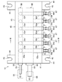
- FIG. 3 is a plan view of the branching unit of the embodiment.
- FIG. 4 is a front view of the branch unit of the embodiment.
- FIG. 5 is a left side view of the branching unit of the embodiment.
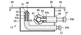
- 6 is a cross-sectional view of the branch unit showing a VI-VI cross section of FIG.
- FIG. 7 is a cross-sectional view of a mechanical pipe joint.
- the air conditioner (10) is a refrigeration system that performs a vapor compression refrigeration cycle, and performs air conditioning of the indoor space (94) (specifically, a living room, a corridor, etc.).
- the air conditioning apparatus (10) of the present embodiment includes one outdoor unit (11), six indoor units (12a to 12f), and one branching unit (13).
- the numbers of outdoor units (11), indoor units (12a to 12f), and branch units (13) shown here are all merely examples.
- the outdoor unit (11) which is a heat source unit is installed outside the building (90).
- the outdoor unit (11) includes a compressor, an outdoor heat exchanger, an outdoor expansion valve, an outdoor fan, and the like.
- the indoor units (12a to 12f) which are the use side units are installed indoors in the building (90).
- Each indoor unit (12a to 12f) in the present embodiment is a ceiling-mounted type.
- each indoor unit (12a to 12f) includes an indoor heat exchanger, an indoor expansion valve, an indoor fan, and the like. Note that all the indoor units (12a to 12f) do not have to be ceiling-mounted, and some of the indoor units (12a to 12f) may be wall-mounted.
- the branching unit (13) is installed indoors of the building (90) together with the indoor units (12a to 12f).
- the branching unit (13) includes a liquid side header (50), a gas side header (60), and a casing (40) for containing the liquid side header (50) and the gas side header (60) Equipped with
- the liquid side header (50) is provided with one liquid side collecting pipe (51) and six liquid side branch pipes (53a to 53f)
- the gas side header (60) is provided with one gas side A collecting pipe (61) and six gas side branch pipes (63a to 63f) are provided.
- a refrigerant circuit (15) is formed by connecting the outdoor unit (11), the branch unit (13) and the indoor units (12a to 12f) by piping. Be done.
- the refrigerant circuit (15) performs a vapor compression refrigeration cycle by circulating the filled refrigerant.
- the outdoor unit (11) is connected to all the indoor units (12a to 12f) via the branch unit (13).
- the outdoor unit (11) is connected to the branch unit (13) through the liquid side main pipe (21) and the gas side main pipe (26).
- Each indoor unit (12a to 12f) is connected to the branch unit (13) via the liquid side branch pipes (22a to 22f) and the gas side branch pipes (27a to 27f).
- six indoor units (12a to 12f) are arranged in parallel.
- the outdoor unit (11) is connected to the liquid side collecting port (52) of the liquid side header (50) through the liquid side trunk pipe (21), and the gas is connected through the gas side trunk pipe (26) Connect to the gas side collection port (62) of the side header (60).
- the first indoor unit (12a) is connected to the first liquid side branch pipe (53a) of the liquid side header (50) through the first liquid side branch pipe (22a), and through the first gas side branch pipe (27a) Is connected to the first gas side branch pipe (63a) of the gas side header (60).
- the second indoor unit (12b) is connected to the second liquid side branch pipe (53b) of the liquid side header (50) through the second liquid side branch pipe (22b), and through the second gas side branch pipe (27b) And the second gas side branch pipe (63b) of the gas side header (60).
- the third indoor unit (12c) is connected to the third liquid side branch pipe (53c) of the liquid side header (50) through the third liquid side branch pipe (22c), and through the third gas side branch pipe (27c) And the third gas side branch pipe (63c) of the gas side header (60).
- the fourth indoor unit (12d) is connected to the fourth liquid side branch pipe (53d) of the liquid side header (50) through the fourth liquid side branch pipe (22d), and through the fourth gas side branch pipe (27d) Is connected to the fourth gas side branch pipe (63d) of the gas side header (60).
- the fifth indoor unit (12e) is connected to the fifth liquid side branch pipe (53e) of the liquid side header (50) through the fifth liquid side branch pipe (22e), and through the fifth gas side branch pipe (27e) Is connected to the fifth gas side branch pipe (63e) of the gas side header (60).
- the sixth indoor unit (12f) is connected to the sixth liquid side branch pipe (53f) of the liquid side header (50) through the sixth liquid side branch pipe (22f), and through the sixth gas side branch pipe (27f) Is connected to the sixth gas side branch pipe (63f) of the gas side header (60).
- the first indoor unit (12a) and the second indoor unit (12b) have larger rated capacities than the remaining indoor units (12c to 12f). Therefore, the first liquid side branch pipe (22a) and the second liquid side branch pipe (22b) are thicker than the remaining liquid side branch pipes (22c to 22f), and the first gas side branch pipe (27a) and the second gas side branch pipe ( 27b) is thicker than the remaining gas side branch pipes (27c to 27f).
- first liquid branch pipe (22a) and the second liquid branch pipe (22b) have larger outer diameters and inner diameters than the remaining liquid branch pipes (22c to 22f), and the first gas branch pipe (27a) And the second gas side branch pipe (27b) are larger in outer diameter and inner diameter respectively than the remaining gas side branch pipes (27c to 27f).
- the liquid side main pipe (21), the liquid side header (50) of the branch unit (13), and the first to sixth liquid side branch pipes (53a to 53f) are an outdoor unit (11) and an indoor unit (12a). Configure the liquid side communication pipe (20) to connect ⁇ 12f). Further, the gas side main pipe (26), the gas side header (60) of the branch unit (13), and the first to sixth gas side branch pipes (63a to 63f) are the outdoor unit (11) and the indoor unit.
- the gas side communication pipe (25) connecting (12a to 12f) is configured.
- the branch unit (13) is provided in the liquid side communication pipe (20) and the gas side communication pipe (25) of the air conditioner (10).
- the air conditioner (10) performs a cooling operation for cooling the indoor space (94) and a heating operation for heating the indoor space (94).
- the outdoor heat exchanger of the outdoor unit (11) functions as a condenser
- the indoor heat exchangers of each indoor unit (12a to 12f) function as an evaporator.
- the refrigerant condensed in the outdoor unit (11) flows through the liquid side main pipe (21) into the liquid side header (50) of the branch unit (13), and the first to sixth liquid side branch pipes ( 22f) and flows into the indoor units (12a to 12f), and absorbs heat from indoor air in each of the indoor units (12a to 12f) to evaporate.
- Each indoor unit (12a to 12f) cools the air sucked from the indoor space (94) with a refrigerant and then blows it out to the indoor space (94).
- each indoor unit (12a to 12f) into the corresponding gas side branch pipe (27a to 27f) flows into the gas side header (60) of the branch unit (13), and after merging, the gas side trunk pipe (26) Flow to the outdoor unit (11).
- the indoor heat exchangers of the indoor units (12a to 12f) function as a condenser
- the outdoor heat exchangers of the outdoor unit (11) function as an evaporator.
- the gas refrigerant flowing from the outdoor unit (11) into the gas side main pipe (26) flows into the gas side header (60) of the branch unit (13), and the first to sixth gas side branch pipes (27a) It is distributed to ⁇ 27f), flows into the indoor units (12a to 12f), and is released to indoor air in each of the indoor units (12a to 12f) to condense.
- Each indoor unit (12a to 12f) heats the air drawn from the indoor space (94) with a refrigerant and then blows it out to the indoor space (94).
- the branch unit (13) includes the liquid side header (50), the gas side header (60), and the casing (40) that accommodates the liquid side header (50) and the gas side header (60). Prepare.
- the detailed configuration of the branch unit (13) will be described with reference to FIGS. 3 to 7.
- the liquid side header (50) includes one liquid side collecting pipe (51) and six liquid side branch pipes (53a to 53f). Moreover, the liquid side header (50) is covered with a heat insulating material (55). The number of the liquid side branch pipes (53a to 53f) shown here is just an example.
- the liquid side collecting pipe (51) is a copper pipe formed in a straight pipe whose one end is sealed.
- the other end of the liquid side collecting pipe (51) is an open end, and constitutes a liquid side collecting port (52).
- a mechanical pipe joint (56) is attached to the other end of the liquid side collecting pipe (51).
- the mechanical pipe joint (56) will be described later.
- the liquid side collecting pipe (51) is connected to the liquid side trunk pipe (21) via a mechanical pipe joint (56). That is, in the liquid side header (50), the liquid side collecting port (52) is connected to the liquid side main pipe (21).
- each of the liquid side branch pipes (53a to 53f) is a copper pipe formed in an L-shape with both ends opened.
- Each liquid side branch pipe (53a to 53f) is thinner than the liquid side collecting pipe (51). That is, the outer diameter and the inner diameter of each of the liquid side branch pipes (53a to 53f) are smaller than that of the liquid side collecting pipe (51).
- One end (base end) of each liquid side branch pipe (53a to 53f) is connected to the liquid side collecting pipe (51), and the other end (protruding end) constitutes a liquid side branch port (54a to 54f).
- the respective liquid side branch pipes (53a to 53f) project in the substantially same direction from the liquid side collecting pipe (51) to the side. Further, the respective liquid side branch pipes (53a to 53f) are arranged in a line at a substantially constant pitch in the axial direction of the liquid side collecting pipe (51).
- a flared pipe joint (57) is provided at the tip end (end on the liquid side branch port (54a to 54f) side) of each liquid side branch pipe (53a to 53f). In FIG. 4, illustration of the flared pipe joint (57) is omitted.
- Each liquid side branch pipe (53a to 53f) is connected to the corresponding liquid side branch pipe (22a to 22f) through a flared pipe joint (57).
- the first liquid side branch port (54a) is the first liquid side branch pipe (22a)
- the second liquid side branch port (54b) is the second liquid side branch pipe (22b)
- the third fluid side branch port (54c) is the third fluid side branch pipe (22c)
- the fourth fluid side branch port (54d) is the fourth fluid side branch pipe (22d)
- the fifth fluid side branch port (54e) is The sixth fluid side branch port (54f) is connected to the fifth fluid side branch pipe (22e) and the sixth fluid side branch pipe (22f), respectively.
- the first to sixth liquid side branch pipes (53f) are disposed in order from the liquid side collecting port (52) of the liquid side collecting pipe (51) toward the sealing end.
- the first liquid side branch pipe (53a) and the second liquid side branch pipe (53b) disposed closer to the liquid side collecting port (52) are the remaining liquid side branch pipes (53c to 53f) thicker. That is, the first liquid side branch pipe (53a) and the second liquid side branch pipe (53b) have outer diameters and inner diameters larger than those of the third to sixth liquid side branch pipes (53c to 53f).
- the outer diameter and the inner diameter of the first liquid branch pipe (53a) and the second liquid branch pipe (53b) are equal to each other.
- the third to sixth liquid side branch pipes (53c to 53f) have the outer diameter and the inner diameter equal to each other.
- each liquid side branch pipe (53a to 53f) communicates with the liquid side collecting pipe (51). Therefore, in the liquid side header (50), one liquid side collecting port (52) communicates with all the liquid side branch ports (54a to 54f).
- the gas side header (60) includes one gas side collecting pipe (61) and six gas side branch pipes (63a to 63f). Also, the gas side header (60) is covered with a heat insulator (65).
- the number of gas side branch pipes (63a to 63f) shown here is just an example. However, the number of gas side branch pipes (63a to 63f) is equal to the number of liquid side branch pipes (53a to 53f) of the liquid side header (50).
- the gas-side collecting pipe (61) is a copper pipe formed in a straight pipe whose one end is sealed.
- the gas side collecting pipe (61) is thicker than the liquid side collecting pipe (51) of the liquid side header (50). That is, in the gas side collecting pipe (61), each of the outer diameter and the inner diameter is larger than the liquid side collecting pipe (51).
- the other end of the gas side collecting pipe (61) is an open end and constitutes a gas side collecting port (62).
- a mechanical pipe joint (66) is attached to the other end of the gas side collecting pipe (61). The mechanical pipe joint (66) will be described later.
- the gas side collecting pipe (61) is connected to the gas side main pipe (26) via a mechanical pipe joint (66). That is, in the gas side header (60), the gas side collecting port (62) is connected to the gas side main pipe (26).
- Each gas-side branch pipe (63a to 63f) is a copper pipe formed in a straight tubular shape with both ends open. Each gas side branch pipe (63a to 63f) is thinner than the gas side collecting pipe (61). That is, the outer diameter and the inner diameter of each of the gas side branch pipes (63a to 63f) are smaller than that of the gas side collection pipe (61). Each gas side branch pipe (63a to 63f) has one end (base end) connected to the gas side collecting pipe (61), and the other end (protruding end) forms a gas side branch port (64a to 64f). Each gas side branch pipe (63a to 63f) protrudes in the substantially same direction from the gas side collecting pipe (61) toward the side. Further, as shown in FIGS. 3 and 4, the gas side branch pipes (63a to 63f) are arranged in a line at a substantially constant pitch in the axial direction of the gas side collecting pipe (61).
- a flared pipe joint (67) is provided at the other end of each gas side branch pipe (63a to 63f). In FIG. 4, illustration of the flared pipe joint (67) is omitted.
- Each gas side branch pipe (63a to 63f) is connected to a corresponding gas side branch pipe (27a to 27f) through a flared pipe joint (67).
- the first gas side branch port (64a) is the first gas side branch pipe (27a)
- the second gas side branch port (64b) is the second gas side branch pipe (27b)
- the third gas side branch port (64c) is the third gas side branch pipe (27c)
- the fourth gas side branch port (64d) is the fourth gas side branch pipe (27d)
- the fifth gas side branch port (64e) is The sixth gas side branch port (64f) is connected to the fifth gas side branch pipe (27e) and the sixth gas side branch pipe (27f), respectively.
- the first to sixth gas side branch pipes (63a to 63f) are arranged in order from the gas side collecting port (62) of the gas side collecting pipe (61) to the sealing end .
- the first gas side branch pipe (63a) and the second gas side branch pipe (63b) disposed closer to the gas side collecting port (62) are the remaining gas side branch pipes (63c to 63f) thicker. That is, the first gas side branch pipe (63a) and the second gas side branch pipe (63b) have outer diameters and inner diameters larger than those of the third to sixth gas side branch pipes (63c to 63f).
- the first gas side branch pipe (63a) and the second gas side branch pipe (63b) have the same outer diameter and inner diameter, respectively.
- the third to sixth gas-side branch pipes (63c to 63f) have the outer diameter and the inner diameter equal to each other.
- the gas side branch pipes (63a to 63f) communicate with the gas side collecting pipe (61). Therefore, in the gas side header (60), one gas side collecting port (62) communicates with all the gas side branch ports (64a to 64f).
- the casing (40) is a box-shaped member made of sheet metal.
- the shape of the casing (40) is rectangular.
- the casing (40) has different width, height and depth. Further, the casing (40) is the longest in width, height and shortest among the width, height and depth.
- a large diameter hole (46) and a small diameter hole (47) are formed in the left side panel (41) of the casing (40).
- the left side panel (41) constitutes a first side of the casing (40).
- the large diameter hole (46) is a circular through hole for exposing the gas side collecting port (62) of the gas side header (60).
- the large diameter hole (46) is disposed at the center of the left side panel (41) shown in FIG.
- the small diameter hole (47) is a circular through hole for exposing the liquid side collecting port (52) of the liquid side header (50).
- the diameter of the small diameter hole (47) is smaller than that of the large diameter hole (46).
- the small diameter hole (47) is disposed diagonally above the left of the large diameter hole (46).
- the front panel (42) of the casing (40) is formed with a front hole (48).
- the front panel (42) constitutes a second side of the casing (40).
- the front panel (42) is substantially orthogonal to the left side panel (41).
- the front holes (48) are through holes for exposing the liquid side branch ports (54a to 54f) of the liquid side header (50) and the gas side branch ports (64a to 64f) of the gas side header (60).
- the front hole (48) is formed in a rectangular shape extending along the lower side of the front panel (42).
- the front hole (48) is disposed at the center of the lower side of the front panel (42).
- the casing (40) is provided with four suspension fittings (44).
- the suspension fitting (44) is a connecting portion connected to a suspension bolt (96) for installing the casing (40).
- the hanging bracket (44) is disposed one each in the upper right corner and the upper left corner of the front panel (42), and one each in the upper right corner and the upper left corner of the back panel (43).
- the hanging bracket (44) is a plate-like member that protrudes laterally from the casing (40). In the hanging metal fitting (44), the tip end portion is bent downward like a hook.
- the hanging bracket (44) is formed with a cut (45) for passing the hanging bolt (96).
- the notch (45) is disposed at the center in the width direction of the suspension fitting (44), and extends from the distal end to the proximal end of the suspension bracket (44).
- the liquid side header (50) and the gas side header (60) are accommodated in the casing (40). Although not shown, the liquid side header (50) and the gas side header (60) are fixed to the casing (40) by a stay or the like.
- the axial direction of the liquid side collecting pipe (51) extends in the longitudinal direction (left and right direction in FIG. 4) of the casing (40) 53f) is installed in a posture located below the liquid side collecting pipe (51).
- the liquid-side collecting pipe (51) has its end on the liquid-side collecting port (52) side exposed through the small diameter hole (47) of the casing (40) to the outside of the casing (40).
- a portion near the base end extends in the vertical direction and is connected to the liquid side collecting pipe (51), The part of the inset extends laterally towards the front panel (42) of the casing (40).
- the ends on the liquid side branch ports (54a to 54f) of the liquid side branch pipes (53a to 53f) pass through the front holes (48) of the casing (40) and are exposed to the outside of the casing (40) .
- the axial direction of the gas side collecting pipe (61) extends in the longitudinal direction (left and right direction in FIG. 4) of the casing (40) 63f) is installed in a posture extending laterally from the gas side collecting pipe (61) to the front panel (42) of the casing (40).
- the gas side collecting pipe (61) is disposed above the laterally extending portion of the liquid side branch pipes (53a to 53f). Further, the end on the gas side collecting port (62) side of the gas side collecting pipe (61) penetrates the large diameter hole (46) of the casing (40) and is exposed to the outside of the casing (40).
- each gas side branch pipe (63a to 63f) the end on the gas side branch port (64a to 64f) side penetrates the front surface hole (48) of the casing (40) to the outside of the casing (40) Exposed.
- the gas side branch pipes (63a to 63f) are disposed above the corresponding liquid side branch pipes (53a to 53f).
- the first gas side branch pipe (63a) is above the first liquid side branch pipe (53a)
- the second gas side branch pipe (63b) is above the second liquid side branch pipe (53b).
- the third gas side branch pipe (63c) is above the third liquid side branch pipe (53c)
- the fourth gas side branch pipe (63d) is above the fourth liquid side branch pipe (53d).
- the branch pipe (63e) is disposed above the fifth liquid side branch pipe (53e)
- the sixth gas side branch pipe (63f) is disposed above the sixth liquid side branch pipe (53f). That is, in the branch unit (13), the corresponding liquid side branch ports (54a to 54f) and the gas side branch ports (64a to 64f) are arranged side by side vertically.
- mechanical pipe joints (56, 66) are attached to the liquid side collecting pipe (51) of the liquid side header (50) and the gas side collecting pipe (61) of the gas side header (60)
- the mechanical pipe joint (56, 66) is a pipe joint that connects two pipes by mechanical connection.
- the mechanical pipe joint (56) attached to the liquid side collecting pipe (51) and the mechanical pipe joint (66) mounted to the gas side collecting pipe (61) have the same structure.
- the mechanical pipe joint (56) attached to the liquid side collecting pipe (51) has a smaller diameter than the mechanical pipe joint (66) mounted to the gas side collecting pipe (61).
- the mechanical pipe joint (56, 66) includes one socket member (71), two nut members (74) and two ring members (77).
- the socket member (71) is a tubular member having male threads formed at both ends.
- An annular projection (72) is formed on the inner circumferential surface of the socket member (71) at the central portion in the axial direction.
- the socket member (71) is provided with an O-ring (73) for sealing the gap between the inner peripheral surface of the socket member (71) and the pipe inserted into the socket member (71).
- Two O-rings (73) are provided on one end side and the other end side of the socket member (71).
- the nut member (74) is a tubular member having an internal thread formed at one end. At the other end of the nut member (74), an O-ring (75) is provided for sealing the gap between the inner peripheral surface of the nut member (74) and the pipe inserted into the nut member (74). Further, on the inner peripheral surface of the nut member (74), there is formed a tapered surface (76) whose diameter increases toward the one end side where the female screw is formed.
- the ring member (77) is an annular member having a trapezoidal cross section.
- the outer peripheral surface of the ring member (77) is a tapered surface along the tapered surface (76) of the nut member (74).
- the ring members (77) are disposed one by one inside each of the nut members (74) in a posture in which the end face on the side where the outer diameter is large and the inner diameter is small faces the socket member (71) side. Further, the ring member (77) is disposed such that the outer peripheral surface thereof is in contact with the tapered surface (76) of the nut member (74).
- the installation process is performed first.
- the outdoor unit (11) is installed outside the building (90), and the indoor units (12a to 12f) and the branch unit (13) are installed indoors in the building (90).
- the outdoor unit (11) is installed on the ground.
- the outdoor unit (11) may be installed, for example, on the roof of a building (90).
- the indoor units (12a to 12f) and the branch unit (13) are installed in the ceiling space (95) formed between the ceiling panel (93) and the casing (91) Be done.
- a ceiling bolt (96) which is a supporting member is attached to a ceiling slab (92) which is a part of a frame (91) of a building (90).
- the suspension bolt (96) is a bolt extending downward from the ceiling slab (92).
- the indoor units (12a to 12f) and the branch unit (13) are suspended from the ceiling slab (92) by connecting them to the suspension bolts (96).
- the four suspension fittings (44) are attached to the casing (40) of the branch unit (13).
- the branch unit (13) When attaching the branch unit (13) to the suspension bolt (96), insert the suspension bolt (96) into the notch (45) of each suspension bracket (44), and attach the suspension bracket by the nut attached to the suspension bolt (96) Fix (44) to the suspension bolt (96).
- a first connection step and a second connection step are performed.
- the outdoor unit (11), the branch unit (13), and the indoor units (12a to 12f) are connected by piping to form a refrigerant circuit (15).
- the other may be performed after completion of one, or both may be performed simultaneously in parallel.
- the outdoor unit (11) and the branch unit (13) are connected by the liquid side main pipe (21) and the gas side main pipe (26).
- the liquid side main pipe (21) is connected to the liquid side collecting pipe (51) of the liquid side header (50) through a mechanical pipe joint (56).
- the gas side main pipe (26) is connected to the gas side collecting pipe (61) of the gas side header (60) through a mechanical pipe joint (66).
- the liquid side trunk pipe (21) and the gas side trunk pipe (26) are configured by connecting a plurality of piping members (31, 32) by mechanical pipe joints (33, 34).
- the piping members (31, 32) constituting the liquid-side trunk pipe (21) and the gas-side trunk pipe (26) are produced by brazing a plurality of parts consisting of so-called hard copper pipes.
- These piping members (31, 32) are manufactured in a factory or a workshop and carried into a building (90) in which the air conditioner (10) is installed.
- the liquid side trunk pipe (21) and the gas side trunk pipe (26) are connected by connecting the piping members (31, 32) with the mechanical pipe joint (33, 34). Is made.
- the mechanical pipe joint (33, 34) for connecting the pipe members (31, 32) is a joint for connecting the pipe members (31, 32) by mechanical connection, and is a mechanical pipe joint (56 shown in FIG. 7). , 66).
- the branch units (13) and the indoor units (12a to 12f) are connected by the liquid side branch pipes (22a to 22f) and the gas side branch pipes (27a to 27f).
- Each liquid side branch pipe (22a to 22f) is connected to a corresponding liquid side branch pipe (53a to 53f) of the liquid side header (50) through a flared pipe joint (57).
- Each gas side branch pipe (27a to 27f) is connected to a corresponding gas side branch pipe (63a to 63f) of the gas side header (60) through a flared pipe joint (67).
- the liquid side branch pipes (22a to 22f) and the gas side branch pipes (27a to 27f) are seamless copper pipes made of so-called soft copper pipes.
- Each liquid side branch pipe (22a to 22f) and each gas side branch pipe (27a to 27f) is a site where a long copper pipe carried in a coil form is installed at the site where the air conditioner (10) is installed. Made by cutting at.
- a evacuating step of discharging air from the refrigerant circuit (15) and a leak inspection step of inspecting the presence or absence of the refrigerant leakage from the refrigerant circuit (15) are performed. Then, when it is confirmed that the refrigerant does not leak from the refrigerant circuit (15), a trial run of the air conditioner (10) is performed.
- the branch unit (13) of the air conditioner (10) of the present embodiment includes the liquid side communication pipe (20) and the gas side communication pipe (25) that connect the outdoor unit (11) to the plurality of indoor units (12a to 12f). Provided). And this branching unit (13) is provided “in the liquid side connection pipe (20), one liquid side collecting port (52) for connecting the outdoor unit (11), indoor unit (12a to 12f) And a plurality of liquid side branch ports (54a to 54f) for connecting the liquid side header (50) in which one liquid side collecting port (52) communicates with all the liquid side branch ports (54a to 54f).
- a plurality of gas side connection ports (62) provided in the gas side communication pipe (25) for connecting the outdoor unit (11) and a plurality of indoor units (12a to 12f).
- the liquid side header (50) provided in the liquid side communication pipe (20) and the gas side header (60) provided in the gas side communication pipe (25) are accommodated in the casing (40). It is unitized. And the branching unit (13) of this embodiment which unitized the liquid side header (50) and the gas side header (60) is installed indoors with the indoor units (12a to 12f) of the air conditioner (10). . For this reason, compared with the case where the liquid side header (50) and the gas side header (60) are separately installed, the installation work of the air conditioner (10) can be simplified.
- the liquid side collecting port (52) and the gas side collecting port (62) are circular holes (46, 47) of the left side panel (41) of the casing (40). Exposed to the outside of the casing (40). For this reason, the operation of connecting the liquid side main pipe (21) and the gas side main pipe (26) extending from the outdoor unit (11) to the branch unit (13) can be performed from the same direction with respect to the casing (40). it can. Therefore, according to the present embodiment, the installation work of the air conditioner (10) can be further simplified.
- all the liquid side branch ports (54a to 54f) and all the gas side branch ports (64a to 64f) correspond to the front panel (42) of the casing (40). It is exposed to the outside of the casing (40) from the front hole (48). For this reason, the work of connecting the liquid side branch pipe (22a to 22f) extending from the indoor unit (12a to 12f) and the gas side branch pipe (27a to 27f) to the branch unit (13) is the same for the casing (40). It can be done from the direction. Therefore, according to the present embodiment, the installation work of the air conditioner (10) can be further simplified.
- the liquid side branch ports (54a to 54f) and the gas side branch ports (64a to 64f) are the liquid side collecting port (52) and the gas side setter
- the front panel (42) is exposed to the outside of the casing (40), not the left side panel (41) where the port (62) is exposed. Therefore, the liquid side main pipe (21) and the gas side main pipe (26) connecting the outdoor unit (11) to the branch unit (13) and the indoor units (12a to 12f) are connected to the branch unit (13) It becomes possible to easily secure the installation space of the liquid side branch pipes (22a to 22f) and the gas side branch pipes (27a to 27f).
- a pair of liquid side branch ports (54a to 54f) and gas side branch ports (64a to 64f) connected to the same indoor unit (12a to 12f) are vertically arranged. It is. For this reason, it becomes possible to easily identify the connection point of the liquid side branch pipe (22a to 22f) and the gas side branch pipe (27a to 27f) extending from the indoor unit (12a to 12f) to the branch unit (13). Installation work of the device (10) can be further simplified.
- the liquid side header (50) has a liquid side collecting pipe (51) whose one end is closed and the other end becomes the liquid side collecting port (52), and a liquid side collecting
- a plurality of liquid side branch pipes (53a to 53f) are provided with a plurality of liquid side branch pipes (53a to 53f) projecting laterally from the pipe (51) and whose tips become liquid side branch ports (54a to 54f)
- a gas side assembly is disposed at a predetermined interval in the axial direction of the liquid side collecting pipe (51), while the gas side header (60) has one end closed and the other end a gas side collecting port (62) And a plurality of gas side branch pipes (63a to 63f) projecting laterally from the gas side collecting pipe (61) and whose tips are gas side branch ports (64a to 64f)
- the side branch pipes (63a to 63f) are arranged at predetermined intervals in the axial direction of the gas side collecting pipe (61).
- the liquid side header (50) is provided with liquid side branch pipes (53a to 53f) having different thicknesses, and the thicker liquid side branch pipes (53a, 53b) Located closer to the side aggregation port (52). Therefore, during the cooling operation of the air conditioner (10) in which the refrigerant flows from the liquid side collecting port (52) toward the liquid side branch ports (54a to 54f), the liquid side branch near the liquid side collecting port (52) The flow rate of the refrigerant flowing into the pipe (that is, the relatively thick liquid side branch pipe (53a, 53b)) is secured.
- the gas side header (60) is provided with gas side branch pipes (63a to 63f) having different thicknesses, and the thicker gas side branch pipes (63a, 63b) are disposed closer to the gas side collecting port (62) . Therefore, during heating operation of the air conditioner (10) in which the refrigerant flows from the gas side collecting port (62) toward the gas side branch ports (64a to 64f), the gas side branch close to the gas side collecting port (62) The flow rate of the refrigerant flowing into the pipe (ie, the relatively thick gas side branch pipe (63a, 63b)) is secured.
- the liquid side header (50) is a mechanical pipe coupling (the liquid side trunk pipe (21) is connected to the liquid side collecting port (52) by mechanical coupling ( 56) and a plurality of flared pipe joints (57) for connecting the liquid side branch pipes (22a to 22f) to the liquid side branch ports (54a to 54f), and the gas side header (60) is mechanically connected to the gas One mechanical pipe coupling (66) connecting the gas side trunk pipe (26) to the side collecting port (62) and a plurality connecting the gas side branch pipes (27a to 27f) to the gas side branch ports (64a to 64f) And a flared joint (67).
- liquid side header (50) and the gas side header (60), the liquid side main pipe (21) and the gas side main pipe (26), and the liquid are used without performing brazing using a fire.
- the side branch pipes (22a to 22f) and the gas side branch pipes (27a to 27f) can be connected.
- the casing (40) of the branch unit (13) of this embodiment is connected to the suspension bolt (96) fixed to the building (90) to suspend the casing (40) to the suspension bolt (96). (44) is provided.
- the branch unit (13) of the present embodiment is suspended by the suspension bolt (96) by connecting the suspension bracket (44) of the casing (40) to the suspension bolt (96) fixed to the building (90). It will be For this reason, it is possible to simplify the work of installing the branching unit (13) indoors in the building (90).
- an installation step In the installation step, the outdoor unit (11) is installed outside the building (90), and the indoor units (12a to 12f) and the branching unit (13) are installed indoors in the building (90).
- a liquid side stem is configured by connecting the outdoor unit (11) and the branch unit (13) with each other by connecting a plurality of piping members (31, 32) by mechanical pipe joints (33, 34) Connect by pipe (21) and gas side trunk pipe (26) ".
- the indoor units (12a to 12f) and the branch units (13) are "connected to the liquid side branch pipe (22a to 22f) and the gas side branch pipe (27a to 27f), each of which is constituted by a seamless copper pipe.
- the brazing operation using fire is not performed in the first connection step and the second connection step. That is, in this installation method, brazing work using fire is not performed in the building (90) in which the air conditioner (10) is installed. For this reason, while being able to reduce the man-hour of the work which installs an air conditioning apparatus (10) in a building (90), the safety of the work which installs an air conditioning apparatus (10) in a building (90) can be improved.
- the air conditioner (10) can be installed even in a building that is already in use or a building that can not perform work using fire, such as a convenience store attached to a gas station.
- the air conditioning apparatus (10) of the present embodiment may include a plurality of branching units (13).
- the plurality of branch units (13) are connected in parallel to one another, and the plurality of indoor units are connected to each branch unit (13).
- the air conditioning apparatus (10) of this embodiment may be provided with a plurality of outdoor units (11).
- the plurality of outdoor units (11) are connected in parallel to each other.
- the indoor units (12a to 12f) it is not necessary to connect the indoor units (12a to 12f) to all the branch pipes (53a to 53f, 63a to 63f) of the branch unit (13).
- the indoor unit may be connected only to the branch pipe of the part.
- the branch pipe to which the indoor unit is not connected is sealed by, for example, a blind lid or the like.
- the present disclosure is useful for the branching unit (13), the refrigeration apparatus provided with the branching unit (13), and the installation method of the refrigeration apparatus.
- Air conditioner (refrigerator) 11 Outdoor unit (heat source unit) 12a to 12f 1st to 6th indoor units (use side units) 13 branch unit 20 liquid side communication pipe 21 liquid side trunk pipe 22a to 22f first to sixth liquid side branch pipe 25 gas side communication pipe 26 gas side trunk pipe 27a to 27f first to sixth gas side branch pipe 31, 32 piping member 33, 34 Mechanical fitting 40 Casing 41 Left side panel (first side) 42 front panel (second side) 44 Suspension bracket (connection part) Reference Signs List 50 liquid side header 51 liquid side collecting pipe 52 liquid side collecting port 53a to 53f first to sixth liquid side branch pipes 54a to 54f first to sixth liquid side branch ports 56 mechanical pipe joint 57 flare pipe joint 60 gas side Header 61 Gas side collecting pipe 62 Gas side collecting port 63a to 63f 1st to 6th gas side branch pipe 64a to 64f 1st to 6th gas side branch port 66 Mechanical pipe joint 67 Flare pipe joint 90 Building 96 Suspension bolt ( Support member)
Landscapes
- Engineering & Computer Science (AREA)
- Mechanical Engineering (AREA)
- General Engineering & Computer Science (AREA)
- Chemical & Material Sciences (AREA)
- Combustion & Propulsion (AREA)
- Physics & Mathematics (AREA)
- Thermal Sciences (AREA)
- Other Air-Conditioning Systems (AREA)
- Branch Pipes, Bends, And The Like (AREA)
- Processing Of Stones Or Stones Resemblance Materials (AREA)
- Mechanical Treatment Of Semiconductor (AREA)
Abstract
Dans un dispositif de climatisation, qui est un dispositif de réfrigération, une unité de ramification (13) est disposée dans une conduite de couplage côté liquide et dans une conduite de couplage côté gaz reliant une unité externe à une pluralité d'unités internes. Dans l'unité de ramification (13), un collecteur côté liquide (50) et un collecteur côté gaz (60) sont logés dans un boîtier (40). Le collecteur côté liquide (50) est pourvu d'un orifice combiné côté liquide (52) et d'une pluralité de ports de ramification côté liquide (54a à 54f). Le collecteur côté gaz (60) est pourvu d'un orifice combiné côté gaz (62) et d'une pluralité de ports de ramification côté gaz (64a à 64f). L'unité de ramification (13) est installée à l'intérieur. Le travail pour installer le dispositif de climatisation peut être simplifié en utilisant l'unité de ramification (13).
Priority Applications (4)
| Application Number | Priority Date | Filing Date | Title |
|---|---|---|---|
| ES18900877T ES2921349T3 (es) | 2018-01-22 | 2018-12-18 | Método para instalar un dispositivo de refrigeración |
| MYPI2020003730A MY199612A (en) | 2018-01-22 | 2018-12-18 | Branch unit, refrigeration device, and method for installing refrigeration device |
| EP18900877.4A EP3730874B1 (fr) | 2018-01-22 | 2018-12-18 | Procédé d'installation de dispositif de réfrigération |
| SG11202006660PA SG11202006660PA (en) | 2018-01-22 | 2018-12-18 | Branch unit, refrigeration device, and method for installing refrigeration device |
Applications Claiming Priority (2)
| Application Number | Priority Date | Filing Date | Title |
|---|---|---|---|
| JP2018008218A JP6766084B2 (ja) | 2018-01-22 | 2018-01-22 | 冷凍装置の設置方法 |
| JP2018-008218 | 2018-01-22 |
Publications (1)
| Publication Number | Publication Date |
|---|---|
| WO2019142575A1 true WO2019142575A1 (fr) | 2019-07-25 |
Family
ID=67302155
Family Applications (1)
| Application Number | Title | Priority Date | Filing Date |
|---|---|---|---|
| PCT/JP2018/046488 Ceased WO2019142575A1 (fr) | 2018-01-22 | 2018-12-18 | Unité de ramification, dispositif de réfrigération et procédé d'installation de dispositif de réfrigération |
Country Status (6)
| Country | Link |
|---|---|
| EP (1) | EP3730874B1 (fr) |
| JP (1) | JP6766084B2 (fr) |
| ES (1) | ES2921349T3 (fr) |
| MY (1) | MY199612A (fr) |
| SG (1) | SG11202006660PA (fr) |
| WO (1) | WO2019142575A1 (fr) |
Families Citing this family (1)
| Publication number | Priority date | Publication date | Assignee | Title |
|---|---|---|---|---|
| JP2023057646A (ja) * | 2021-10-12 | 2023-04-24 | 東尾メック株式会社 | ヘッダー構造体 |
Citations (8)
| Publication number | Priority date | Publication date | Assignee | Title |
|---|---|---|---|---|
| JPS63226567A (ja) | 1987-03-14 | 1988-09-21 | ダイキン工業株式会社 | 空気調和装置 |
| JPH01153425U (fr) * | 1988-04-13 | 1989-10-23 | ||
| JPH04217760A (ja) * | 1990-12-20 | 1992-08-07 | Mitsubishi Electric Corp | 空気調和装置 |
| JPH04332356A (ja) * | 1991-02-05 | 1992-11-19 | Daikin Ind Ltd | 空気調和装置 |
| JPH07208831A (ja) * | 1994-01-20 | 1995-08-11 | Mitsubishi Heavy Ind Ltd | 冷凍装置用ディストリビュータ |
| JP2005326090A (ja) * | 2004-05-14 | 2005-11-24 | Mitsubishi Electric Corp | 空気調和装置の冷媒回路分岐ユニット |
| JP2007232286A (ja) * | 2006-03-01 | 2007-09-13 | Higashio Mech Co Ltd | 冷媒配管方法 |
| EP2365253A2 (fr) * | 2010-03-11 | 2011-09-14 | LG Electronics Inc. | Dispositif de climatisation incluant une unité externe et unité de distribution |
Family Cites Families (10)
| Publication number | Priority date | Publication date | Assignee | Title |
|---|---|---|---|---|
| JPS59155381U (ja) * | 1983-04-06 | 1984-10-18 | 因幡電工株式会社 | 複合管 |
| JP3175676B2 (ja) * | 1997-12-05 | 2001-06-11 | ダイキン工業株式会社 | 冷媒分岐ユニット |
| JP3745211B2 (ja) * | 2000-09-21 | 2006-02-15 | 柿沼金属精機株式会社 | 分岐ジョイント |
| JP2004076879A (ja) * | 2002-08-20 | 2004-03-11 | Togo Seisakusho Corp | 配管の施工方法及び配管セット |
| JP2005180003A (ja) * | 2003-12-19 | 2005-07-07 | Bridgestone Corp | 給水・給湯及び排水管の敷設工法 |
| JP2008106933A (ja) * | 2006-09-29 | 2008-05-08 | Aisin Seiki Co Ltd | 分岐管及び及び分岐管を用いた空気調和装置 |
| JP2011163631A (ja) * | 2010-02-09 | 2011-08-25 | Hitachi Appliances Inc | ヒートポンプ給湯機 |
| JP5630102B2 (ja) * | 2010-06-30 | 2014-11-26 | 株式会社富士通ゼネラル | 空気調和機の冷媒分岐ユニット |
| KR20120119268A (ko) * | 2011-04-21 | 2012-10-31 | (주)로커스 | 공기조화기용 알루미늄 서비스밸브 및 그 제조방법 |
| JP6050671B2 (ja) * | 2012-12-07 | 2016-12-21 | ダイキン工業株式会社 | 空気調和装置の配管ユニットの製造方法および空気調和装置の施工方法 |
-
2018
- 2018-01-22 JP JP2018008218A patent/JP6766084B2/ja active Active
- 2018-12-18 ES ES18900877T patent/ES2921349T3/es active Active
- 2018-12-18 EP EP18900877.4A patent/EP3730874B1/fr active Active
- 2018-12-18 MY MYPI2020003730A patent/MY199612A/en unknown
- 2018-12-18 WO PCT/JP2018/046488 patent/WO2019142575A1/fr not_active Ceased
- 2018-12-18 SG SG11202006660PA patent/SG11202006660PA/en unknown
Patent Citations (8)
| Publication number | Priority date | Publication date | Assignee | Title |
|---|---|---|---|---|
| JPS63226567A (ja) | 1987-03-14 | 1988-09-21 | ダイキン工業株式会社 | 空気調和装置 |
| JPH01153425U (fr) * | 1988-04-13 | 1989-10-23 | ||
| JPH04217760A (ja) * | 1990-12-20 | 1992-08-07 | Mitsubishi Electric Corp | 空気調和装置 |
| JPH04332356A (ja) * | 1991-02-05 | 1992-11-19 | Daikin Ind Ltd | 空気調和装置 |
| JPH07208831A (ja) * | 1994-01-20 | 1995-08-11 | Mitsubishi Heavy Ind Ltd | 冷凍装置用ディストリビュータ |
| JP2005326090A (ja) * | 2004-05-14 | 2005-11-24 | Mitsubishi Electric Corp | 空気調和装置の冷媒回路分岐ユニット |
| JP2007232286A (ja) * | 2006-03-01 | 2007-09-13 | Higashio Mech Co Ltd | 冷媒配管方法 |
| EP2365253A2 (fr) * | 2010-03-11 | 2011-09-14 | LG Electronics Inc. | Dispositif de climatisation incluant une unité externe et unité de distribution |
Non-Patent Citations (1)
| Title |
|---|
| See also references of EP3730874A4 |
Also Published As
| Publication number | Publication date |
|---|---|
| MY199612A (en) | 2023-11-09 |
| EP3730874A4 (fr) | 2021-09-08 |
| EP3730874B1 (fr) | 2022-06-15 |
| JP2019128057A (ja) | 2019-08-01 |
| ES2921349T3 (es) | 2022-08-24 |
| JP6766084B2 (ja) | 2020-10-07 |
| EP3730874A1 (fr) | 2020-10-28 |
| SG11202006660PA (en) | 2020-08-28 |
Similar Documents
| Publication | Publication Date | Title |
|---|---|---|
| JP7404213B2 (ja) | 冷凍装置、当該冷凍装置の冷媒配管、及び冷媒配管の製造方法 | |
| JP2023041799A (ja) | 冷凍装置及び当該冷凍装置の冷媒配管 | |
| CN104822996B (zh) | 空调装置的管道单元 | |
| JP6803651B2 (ja) | 冷媒流路切換ユニット | |
| CN204115128U (zh) | 空调机 | |
| WO2019142575A1 (fr) | Unité de ramification, dispositif de réfrigération et procédé d'installation de dispositif de réfrigération | |
| CN102192580A (zh) | 管连接单元和包括该管连接单元的空调器 | |
| JP3822386B2 (ja) | 空気調和装置における室内ユニット | |
| CN105180511A (zh) | 分体落地式空调器、冷媒回收方法以及冷媒回收装置 | |
| KR101620279B1 (ko) | 기밀 테스트용 배관 연결관, 이를 결합한 스테인리스 배관 및 스테인리스 배관 형성방법 | |
| JPH1089723A (ja) | 空気調和装置 | |
| KR20090005185U (ko) | 공기조화기 | |
| KR100803774B1 (ko) | 공기조화기의 설치배관 | |
| CN213685372U (zh) | 配管组件、四通阀组件以及空调系统 | |
| JP2007509296A (ja) | パイプ接続装置及び接続方法 | |
| KR200438741Y1 (ko) | 에어컨 설치배관용 플러그 | |
| CN224003819U (zh) | 阀盒装置及空调系统 | |
| CN224003973U (zh) | 阀盒及阀盒装置 | |
| KR100484871B1 (ko) | 공기조화기의 냉매배관 연결장치 | |
| JP2005164240A (ja) | 空気調和装置における室内ユニット | |
| CN224003818U (zh) | 阀盒装置及空调系统 | |
| JP7292041B2 (ja) | 冷媒漏れ検出システム、ヒートポンプシステム、及び冷媒漏れ報知システム | |
| JP2001153402A (ja) | 冷凍サイクル装置 | |
| JP2015215145A (ja) | ダクト型空気調和機 | |
| CN208804356U (zh) | 一种便于安装的空调管道 |
Legal Events
| Date | Code | Title | Description |
|---|---|---|---|
| 121 | Ep: the epo has been informed by wipo that ep was designated in this application |
Ref document number: 18900877 Country of ref document: EP Kind code of ref document: A1 |
|
| NENP | Non-entry into the national phase |
Ref country code: DE |
|
| ENP | Entry into the national phase |
Ref document number: 2018900877 Country of ref document: EP Effective date: 20200721 |