WO2019171750A1 - コンデンサ及びその製造方法 - Google Patents
コンデンサ及びその製造方法 Download PDFInfo
- Publication number
- WO2019171750A1 WO2019171750A1 PCT/JP2019/000351 JP2019000351W WO2019171750A1 WO 2019171750 A1 WO2019171750 A1 WO 2019171750A1 JP 2019000351 W JP2019000351 W JP 2019000351W WO 2019171750 A1 WO2019171750 A1 WO 2019171750A1
- Authority
- WO
- WIPO (PCT)
- Prior art keywords
- conductive layer
- trenches
- holes
- substrate
- main surface
- Prior art date
- Legal status (The legal status is an assumption and is not a legal conclusion. Google has not performed a legal analysis and makes no representation as to the accuracy of the status listed.)
- Ceased
Links
Images


Classifications
-
- H—ELECTRICITY
- H10—SEMICONDUCTOR DEVICES; ELECTRIC SOLID-STATE DEVICES NOT OTHERWISE PROVIDED FOR
- H10D—INORGANIC ELECTRIC SEMICONDUCTOR DEVICES
- H10D1/00—Resistors, capacitors or inductors
- H10D1/01—Manufacture or treatment
- H10D1/041—Manufacture or treatment of capacitors having no potential barriers
- H10D1/043—Manufacture or treatment of capacitors having no potential barriers using patterning processes to form electrode extensions, e.g. etching
-
- H—ELECTRICITY
- H01—ELECTRIC ELEMENTS
- H01G—CAPACITORS; CAPACITORS, RECTIFIERS, DETECTORS, SWITCHING DEVICES, LIGHT-SENSITIVE OR TEMPERATURE-SENSITIVE DEVICES OF THE ELECTROLYTIC TYPE
- H01G4/00—Fixed capacitors; Processes of their manufacture
- H01G4/002—Details
- H01G4/005—Electrodes
- H01G4/012—Form of non-self-supporting electrodes
-
- H—ELECTRICITY
- H01—ELECTRIC ELEMENTS
- H01G—CAPACITORS; CAPACITORS, RECTIFIERS, DETECTORS, SWITCHING DEVICES, LIGHT-SENSITIVE OR TEMPERATURE-SENSITIVE DEVICES OF THE ELECTROLYTIC TYPE
- H01G4/00—Fixed capacitors; Processes of their manufacture
- H01G4/33—Thin- or thick-film capacitors (thin- or thick-film circuits; capacitors without a potential-jump or surface barrier specially adapted for integrated circuits, details thereof, multistep manufacturing processes therefor)
-
- H—ELECTRICITY
- H01—ELECTRIC ELEMENTS
- H01G—CAPACITORS; CAPACITORS, RECTIFIERS, DETECTORS, SWITCHING DEVICES, LIGHT-SENSITIVE OR TEMPERATURE-SENSITIVE DEVICES OF THE ELECTROLYTIC TYPE
- H01G4/00—Fixed capacitors; Processes of their manufacture
- H01G4/38—Multiple capacitors, i.e. structural combinations of fixed capacitors
- H01G4/385—Single unit multiple capacitors, e.g. dual capacitor in one coil
-
- H—ELECTRICITY
- H10—SEMICONDUCTOR DEVICES; ELECTRIC SOLID-STATE DEVICES NOT OTHERWISE PROVIDED FOR
- H10D—INORGANIC ELECTRIC SEMICONDUCTOR DEVICES
- H10D1/00—Resistors, capacitors or inductors
- H10D1/01—Manufacture or treatment
- H10D1/041—Manufacture or treatment of capacitors having no potential barriers
- H10D1/042—Manufacture or treatment of capacitors having no potential barriers using deposition processes to form electrode extensions
-
- H—ELECTRICITY
- H10—SEMICONDUCTOR DEVICES; ELECTRIC SOLID-STATE DEVICES NOT OTHERWISE PROVIDED FOR
- H10D—INORGANIC ELECTRIC SEMICONDUCTOR DEVICES
- H10D1/00—Resistors, capacitors or inductors
- H10D1/60—Capacitors
- H10D1/68—Capacitors having no potential barriers
- H10D1/692—Electrodes
- H10D1/696—Electrodes comprising multiple layers, e.g. comprising a barrier layer and a metal layer
-
- H—ELECTRICITY
- H10—SEMICONDUCTOR DEVICES; ELECTRIC SOLID-STATE DEVICES NOT OTHERWISE PROVIDED FOR
- H10D—INORGANIC ELECTRIC SEMICONDUCTOR DEVICES
- H10D1/00—Resistors, capacitors or inductors
- H10D1/60—Capacitors
- H10D1/68—Capacitors having no potential barriers
- H10D1/692—Electrodes
- H10D1/711—Electrodes having non-planar surfaces, e.g. formed by texturisation
- H10D1/716—Electrodes having non-planar surfaces, e.g. formed by texturisation having vertical extensions
-
- H—ELECTRICITY
- H10—SEMICONDUCTOR DEVICES; ELECTRIC SOLID-STATE DEVICES NOT OTHERWISE PROVIDED FOR
- H10D—INORGANIC ELECTRIC SEMICONDUCTOR DEVICES
- H10D84/00—Integrated devices formed in or on semiconductor substrates that comprise only semiconducting layers, e.g. on Si wafers or on GaAs-on-Si wafers
- H10D84/01—Manufacture or treatment
- H10D84/02—Manufacture or treatment characterised by using material-based technologies
- H10D84/03—Manufacture or treatment characterised by using material-based technologies using Group IV technology, e.g. silicon technology or silicon-carbide [SiC] technology
- H10D84/038—Manufacture or treatment characterised by using material-based technologies using Group IV technology, e.g. silicon technology or silicon-carbide [SiC] technology using silicon technology, e.g. SiGe
Definitions
- the first main surface has a first main surface and a second main surface, and the first main surface is provided with one or more first trenches, and the side walls of the one or more first trenches are provided with the first main surface.
- a substrate provided with a plurality of first holes each extending in a first direction inclined with respect to the side wall of one trench, the first main surface, the side walls and the bottom surface of the first trench, and the plurality of first
- a first conductive layer covering a sidewall of the hole; and the first main surface, the sidewall and bottom surface of the first trench, and the one or more first holes, with the first conductive layer interposed therebetween.
- a capacitor is provided that includes a second conductive layer facing a side wall, and a dielectric layer interposed between the first conductive layer and the second conductive layer.
- FIG. 1 is a plan view schematically showing the capacitor according to the first embodiment.
- FIG. 2 is a cross-sectional view taken along line II-II of the capacitor shown in FIG. 3 is a cross-sectional view of the capacitor shown in FIG. 1 taken along the line III-III.
- 4 is a cross-sectional view taken along line IV-IV of the capacitor shown in FIG.
- FIG. 5 is a cross-sectional view taken along line VV of the capacitor shown in FIG. 6 is a cross-sectional view taken along line VI-VI of the capacitor shown in FIG.
- the “length direction” of the first or second recess is the length direction of the orthogonal projection of the first or second recess on a plane perpendicular to the thickness direction of the substrate 10. Accordingly, the fact that the length direction of the first recess R1 and the length direction of the second recess R2 intersect each other means that the length direction of the orthogonal projection of the first recess on the plane perpendicular to the thickness direction of the substrate 10 And the length direction of the orthogonal projection of the second concave portion on this plane.
- the sum D1 + D2 of the depth D1 of the first recess R1 and the depth D2 of the second recess R2 is equal to or greater than the thickness T of the substrate 10. If this structure is employ
- cross section parallel to the depth direction of the first recess R1 and the second recess R2 is rectangular.
- These cross sections need not be rectangular.
- these cross sections may have a tapered shape.
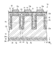
- the first conductive layer 20a is provided on the substrate 10 as shown in FIGS.
- the first conductive layer 20a and the substrate 10 constitute a conductive substrate CS.
- the first conductive layer 20a includes a first portion P1 shown in FIGS. 2 to 4 and 6, a second portion P2 shown in FIGS. 2, 3, 5, and 6, and FIGS.
- the third portion P3 shown in FIG. 3 and the fourth portion P4 shown in FIGS. 3 to 6 are included.
- the first portion P1 is a portion provided on the first main surface S1 in the first conductive layer 20a.
- the second portion P2 is a portion provided on the second main surface S2 in the first conductive layer 20a.
- the third portion P3 is a portion provided on the inner surface of the first recess R1 in the first conductive layer 20a.
- the fourth portion P4 is a portion provided on the inner surface of the second recess R2 in the first conductive layer 20a.
- the second conductive layer 20b faces the first conductive layer 20a with the dielectric layer 50 interposed therebetween.
- the second conductive layer 20b is made of polysilicon doped with impurities to improve conductivity, or a metal or alloy such as nickel or copper.
- the second conductive layer 20b may have a single layer structure or a multilayer structure.
- the second conductive layer 20b is formed such that the first concave portion R1 and the second concave portion R2 are completely filled with the first conductive layer 20a, the second conductive layer 20b, and the dielectric layer 50.
- the second conductive layer 20b may be a layer conformal to the first conductive layer 20a. That is, the second conductive layer 20b may be a layer having a substantially uniform thickness. In this case, the first recess R1 and the second recess R2 are not completely filled with the first conductive layer 20a, the second conductive layer 20b, and the dielectric layer 50.
- the second conductive layer 20b is provided with a plurality of through holes.
- these through holes are portions of the second conductive layer 20b facing the first main surface with the first conductive layer 20a and the dielectric layer 50 interposed therebetween, and the first recess R1 and the second recess It is provided at a position corresponding to the intersection with R2.
- the second conductive layer 20b may be provided with through holes at other positions. Further, only one through hole may be provided in the second conductive layer 20b.
- the dielectric layer 50 is interposed between the first conductive layer 20a and the second conductive layer 20b.
- the dielectric layer 50 is a layer that is conformal to the first conductive layer 20a.
- the dielectric layer 50 electrically insulates the first conductive layer 20a and the second conductive layer 20b from each other.
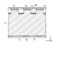
- the insulating layer 60 includes a first insulating layer 61 and a second insulating layer 62.
- the first insulating layer 61 covers the fifth portion P5 and the seventh portion P7 of the second conductive layer 20b.
- the first insulating layer 61 further covers the side wall of the through hole provided in the second conductive layer 20 b and the side wall of the through hole provided in the dielectric layer 50.
- the first insulating layer 61 is made of an inorganic insulator such as silicon nitride, for example.
- the insulating layer 60 is provided with a plurality of through holes. Some of these through holes are connected to the through holes provided in the dielectric layer 50 through the through holes provided in the second conductive layer 20b, and together with these, the first contact holes are formed. The remainder of the through hole provided in the insulating layer 60 is provided at an intermediate position between the first contact holes adjacent in the Y direction to form a second contact hole.
- FIG. 7 is a cross-sectional view schematically showing a first catalyst layer forming step in manufacturing the capacitor shown in FIGS.
- FIG. 8 is a cross-sectional view schematically showing a second catalyst layer forming step in manufacturing the capacitor shown in FIGS.
- FIG. 9 is a cross-sectional view schematically showing an etching process in manufacturing the capacitor shown in FIGS.
- FIG. 10 is another cross-sectional view schematically showing an etching process in manufacturing the capacitor shown in FIGS.
- a catalyst layer 80a is formed on a region of the first main surface S1 that is not covered by the first mask layer 90a.
- the catalyst layer 80a is, for example, a discontinuous layer containing a noble metal.
- the catalyst layer 80a is a granular layer made of catalyst particles 81a containing a noble metal.
- the catalyst layer 80b is formed on a region of the second main surface S2 that is not covered with the second mask layer 90b.
- the catalyst layer 80b is, for example, a discontinuous layer containing a noble metal.
- the catalyst layer 80b is assumed to be a granular layer made of catalyst particles 81b containing a noble metal.
- the second mask layer 90b is formed on the second main surface S2, and subsequently, the catalyst layer 80a and the catalyst particles 81a are formed, and then The catalyst layer 80b and the catalyst particles 81b may be formed.
- the substrate is immersed in a plating solution to form the catalyst layer 80a and The catalyst particles 81a, the catalyst layer 80b, and the catalyst particles 81b may be formed at the same time.
- the laminated structure including the first conductive layer 20a, the dielectric layer 50, and the second conductive layer 20b is not only on the first main surface S1, but also on the second main surface S2 and the first through holes. It is also provided in TH1. Therefore, this capacitor 1A can achieve a large electric capacity.
- the first recess R1 and the second recess R2 are trenches.
- the above laminated structure is also provided on the sidewall and bottom surface of the trench. Therefore, this capacitor 1A can achieve a particularly large electric capacity.
- the first recess R1 and the second recess R2 intersect each other, and the sum D1 + D2 of the depths is equal to or greater than the thickness T of the substrate 10. Therefore, when the first recess R1 and the second recess R2 are formed, the first through hole TH1 is generated at a position where they intersect. That is, unlike the case where the first concave portion R1 and the second concave portion R2 whose sum D1 + D2 is smaller than the thickness T are simply formed on the first main surface S1 and the second main surface S2, respectively, the first concave portion R1 and the second concave portion R2 In addition to the step of forming R2, there is no need to perform a step of separately forming the first through hole TH1.
- both electrodes 70a and 70b can be disposed on one side of the capacitor 1A. That is, unlike the case where the first recess R1 and the second recess R2 whose sum D1 + D2 is smaller than the thickness T are simply formed on the first main surface S1 and the second main surface S2, respectively, the electrodes are formed on the second main surface S2. Since there is no need to form 70a and 70b and wirings similar thereto, the number of processes can be greatly reduced. Furthermore, the capacitor 1A employing such a configuration can be easily mounted on a wiring board or the like.
- the third conductive layer 20c is provided on the second dielectric layer 50b.
- the third conductive layer 20c for example, a configuration similar to that of the second conductive layer 20b can be employed.
- the electrodes 70a and 70b and the pads 70c and 70d shown in FIG. 1 are formed of a laminated body that further includes the third metal layer 73 in addition to the first metal layer 71 and the second metal layer 72. ing.
- the third metal layer 73 for example, the same configuration as that of the first metal layer 71 can be adopted.
- the electrode 70a is not in contact with the second conductive layer 20b, and a part of the comb tooth portion is in contact with the first conductive layer 20a. A part is in contact with the third conductive layer 20c. That is, the first conductive layer 20a and the third conductive layer 20c are electrically connected to each other.
- the electrode 70b is not in contact with the first conductive layer 20a and the third conductive layer 20c, and the comb tooth portion is in contact with the second conductive layer 20b. That is, in this capacitor 1B, the electrode 70a is a first electrode and the electrode 70b is a second electrode.
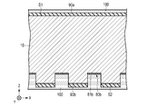
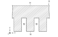
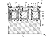
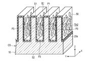
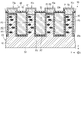
- FIG. 14 is a cross-sectional view schematically showing a capacitor according to the third embodiment.
- FIG. 15 is a perspective view schematically showing a part of the capacitor shown in FIG. 15 illustrates a structure in which the electrode 70b, the electrode 70a, the insulating layer 60, and the second conductive layer 20b are omitted from the capacitor 1C illustrated in FIG.
- a capacitor 1C shown in FIG. 14 is the same as the capacitor 1A according to the first embodiment except that the following configuration is adopted.
- the substrate 10 is etched under the action of a noble metal as a catalyst to form the second through hole TH2 shown in FIG.
- the substrate 10 is etched with an etchant.
- the substrate 10 is immersed in a liquid etching agent, and the etching agent is brought into contact with the substrate 10.
- the etching agent those described in the first embodiment can be used.
- first recesses R1 are formed on the first main surface S1 of the substrate 10
- second recesses R2 are formed on the second main surface S2 of the substrate 10.
- the first recess R1 and the second recess R2 are formed, for example, by MacEch described in the first embodiment.
- the first recess R1 and the second recess R2 are trenches.
- the above laminated structure is also provided on the sidewall and bottom surface of the trench. Therefore, this capacitor can achieve a particularly large capacitance.
- the first recess R1 and the second recess R2 intersect each other, and the sum D1 + D2 of the depths is equal to or greater than the thickness T of the substrate 10. Therefore, when the first recess R1 and the second recess R2 are formed, the first through hole TH1 is generated at a position where they intersect. That is, unlike the case where the first concave portion R1 and the second concave portion R2 whose sum D1 + D2 is smaller than the thickness T are simply formed on the first main surface S1 and the second main surface S2, respectively, the first concave portion R1 and the second concave portion R2 In addition to the step of forming R2, there is no need to perform a step of separately forming the first through hole TH1.
- the laminated structure including the first conductive layer 20a, the dielectric layer 50, and the second conductive layer 20b has the first main surface S1 and the first concave portion. Not only on the side wall and bottom surface of R1, but also on the side wall of the first hole H1 and the side wall of the second hole H2. That is, the first conductive layer 20a further covers the side wall of the first hole H1 and the side wall of the second hole H2 in addition to the first main surface S1 and the side walls and bottom surface of the first recess R1.
- FIG. 23 is a photomicrograph showing a cross section of the capacitor shown in FIG.
- the micrograph in FIG. 23 is a cross-sectional micrograph corresponding to FIG.
- the vertical direction is the X direction
- the horizontal direction is the Y direction.
- the etching proceeds in the thickness direction of the catalyst layer.
- the first hole H1 and the second hole H2 in this capacitor are the same as the first hole H1 and the second hole H2 of the capacitor 1D according to the fifth embodiment.
- the hole density in the side wall of the first recess R1 that is, the ratio between the total number of the first holes H1 and the second holes H2 provided in the side wall and the area of the side wall is the hole density described in the third embodiment. It is preferable to be within the range. Further, the hole density in the side wall of the second recess R2, that is, the ratio of the total number of the third holes H3 and the fourth holes H4 provided in the side wall and the area of the side wall is also described in the third embodiment. It is preferable to be within the range of the pore density.
- the rest may be omitted.
- the orientation of the crystals constituting the substrate has an influence on the etching progress direction.
- the etching is likely to proceed in a direction parallel to the ⁇ 110> axis or an equivalent axis, for example, a direction parallel to the ⁇ 110> axis. Therefore, according to the method described above, the structure shown in FIG. 24 is obtained.
- the capacitor according to the third to sixth embodiments instead of the laminated structure of the first conductive layer 20a, the dielectric layer 50, and the second conductive layer 20b, like the capacitor 1B according to the second embodiment, A stacked structure of the first conductive layer 20a, the first dielectric layer 50a, the second conductive layer 20b, the second dielectric layer 50b, and the third conductive layer 20c may be included.
Landscapes
- Engineering & Computer Science (AREA)
- Power Engineering (AREA)
- Microelectronics & Electronic Packaging (AREA)
- Manufacturing & Machinery (AREA)
- Semiconductor Integrated Circuits (AREA)
- Fixed Capacitors And Capacitor Manufacturing Machines (AREA)
- Weting (AREA)
Abstract
Description
図1は、第1実施形態に係るコンデンサを概略的に示す平面図である。図2は、図1に示すコンデンサのII-II線に沿った断面図である。図3は、図1に示すコンデンサのIII-III線に沿った断面図である。図4は、図1に示すコンデンサのIV-IV線に沿った断面図である。図5は、図1に示すコンデンサのV-V線に沿った断面図である。図6は、図1に示すコンデンサのVI-VI線に沿った断面図である。
第1絶縁層61は、第2導電層20bの第5部分P5及び第7部分P7を覆っている。第1絶縁層61は、第2導電層20bに設けられた貫通孔の側壁と、誘電体層50に設けられた貫通孔の側壁とを更に覆っている。第1絶縁層61は、例えば、シリコン窒化物などの無機絶縁体からなる。
絶縁層60は、多層構造を有していてもよく、単層構造を有していてもよい。
図7は、図1乃至図6に示すコンデンサの製造における第1触媒層形成工程を概略的に示す断面図である。図8は、図1乃至図6に示すコンデンサの製造における第2触媒層形成工程を概略的に示す断面図である。図9は、図1乃至図6に示すコンデンサの製造におけるエッチング工程を概略的に示す断面図である。図10は、図1乃至図6に示すコンデンサの製造におけるエッチング工程を概略的に示す他の断面図である。図11は、図9及び図10のエッチング工程によって得られる構造の一例を概略的に示す断面図である。図12は、図11に示す構造の他の断面図である。
即ち、先ず、図7及び図8に示すように、基板10上に、第1貴金属を含んだ第1触媒層80a及び80bを形成する。第1触媒層80a及び80bは、それぞれ、第1主面S1及び第2主面S2を部分的に覆うように形成する。
第1マスク層90aは、第1凹部R1に対応した位置で開口している。第1マスク層90aは、第1主面S1のうち第1マスク層90aによって覆われた部分が、後述する貴金属と接触するのを防止する。
第2マスク層90bは、第2凹部R2に対応した位置で開口している。第2マスク層90bは、第2主面S2のうち第2マスク層90bによって覆われた部分が、貴金属と接触するのを防止する。
エッチング剤100における弗化水素の濃度は、1mol/L乃至20mol/Lの範囲内にあることが好ましく、5mol/L乃至10mol/Lの範囲内にあることがより好ましく、3mol/L乃至7mol/Lの範囲内にあることが更に好ましい。弗化水素濃度が低い場合、高いエッチングレートを達成することが難しい。弗化水素濃度が高い場合、過剰なサイドエッチングを生じる可能性がある。
エッチング剤100は、水などの他の成分を更に含んでいてもよい。
図13は、第2実施形態に係るコンデンサを概略的に示す断面図である。
加えて、このコンデンサ1Bでは、第1導電層20aと第1誘電体層50aと第2導電層20bと第2誘電体層50bと第3導電層20cとが積層構造を形成している。即ち、このコンデンサ1Bでは、コンデンサ1Aと比較して、より多くの導電層が誘電体層を間に挟んで積層されている。それ故、このコンデンサ1Bは、より大きな電気容量を達成し得る。
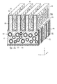
図14は、第3実施形態に係るコンデンサを概略的に示す断面図である。図15は、図14に示すコンデンサの一部を概略的に示す斜視図である。なお、図15には、図14に示すコンデンサ1Cから、電極70b、電極70a、絶縁層60、及び第2導電層20bを省略した構造を描いている。
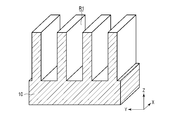
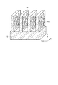
図16は、図14に示すコンデンサの製造に使用する、トレンチが設けられた基板の一例を概略的に示す斜視図である。図17は、図14に示すコンデンサの製造における触媒層形成工程を概略的に示す斜視図である。図18は、図14に示すコンデンサの製造におけるエッチング工程によって得られる構造の一例を概略的に示す斜視図である。
即ち、先ず、図17に示すように、第1凹部R1の側壁上に、触媒粒子81aを堆積させる。触媒粒子81aの堆積は、触媒粒子81a間に十分な大きさの隙間が生じるように行う。
図19は、第4実施形態に係るコンデンサの一部を概略的に示す斜視図である。
第4実施形態に係るコンデンサは、以下の構成を採用したこと以外は、第1実施形態に係るコンデンサ1Aと同様である。
図20は、第5実施形態に係るコンデンサを概略的に示す断面図である。図21は、図20に示すコンデンサの一部を概略的に示す斜視図である。図22は、図21に示すコンデンサのXXII-XXII線に沿った断面図である。なお、図21には、図20に示すコンデンサ1Dから、電極70b、電極70a、絶縁層60、及び第2導電層20bを省略した構造を描いている。
従って、上記の方法によると、図20乃至図23に示した構造が得られる。
図24は、第6実施形態に係るコンデンサの一部を概略的に示す斜視図である。
第6実施形態に係るコンデンサは、以下の構成を採用したこと以外は、第4実施形態に係るコンデンサと同様である。
Claims (36)
- 第1面と第2面とを有し、前記第1面から前記第2面まで各々が延びた1以上の第1貫通孔が設けられた基板と、
前記第1面と前記第2面と前記1以上の第1貫通孔の側壁とを覆った第1導電層と、
前記第1導電層を間に挟んで、前記第1面と前記第2面と前記1以上の第1貫通孔の側壁とに向き合った第2導電層と、
前記第1導電層と前記第2導電層との間に介在した誘電体層と
を備えたコンデンサ。 - 前記第1面及び前記第2面は、それぞれ、前記基板の厚さ方向に垂直な第1及び第2主面であり、前記1以上の貫通孔は、前記厚さ方向に各々が延びた1以上の貫通孔である請求項1に記載のコンデンサ。
- 1以上の第1トレンチが前記第1主面に設けられ、1以上の第2トレンチが前記第2主面に設けられ、前記1以上の第1トレンチの長さ方向と前記1以上の第2トレンチの長さ方向とは互いに交差し、前記1以上の第1トレンチと前記1以上の第2トレンチとは互いに繋がって前記1以上の第1貫通孔を形成している請求項2に記載のコンデンサ。
- 前記第1導電層は、前記1以上の第1トレンチの側壁及び底面と、前記1以上の第2トレンチの側壁及び底面とを更に覆い、前記第2導電層は、前記第1導電層を間に挟んで、前記1以上の第1トレンチの前記側壁及び前記底面と、前記1以上の第2トレンチの前記側壁及び前記底面とに更に向き合った請求項3に記載のコンデンサ。
- 前記1以上の第1トレンチの各々の深さと前記1以上の第2トレンチの各々の深さとの和は、前記基板の厚さ以上である請求項3又は4に記載のコンデンサ。
- 前記1以上の第1トレンチと前記1以上の第2トレンチとは、それらが交差した位置で前記1以上の第1貫通孔を形成している請求項3乃至5の何れか1項に記載のコンデンサ。
- 前記1以上の第1トレンチは複数の第1トレンチであり、前記基板のうち前記複数の第1トレンチの隣り合った2つによって各々が挟まれた1以上の部分には、前記隣り合った2つの第1トレンチの一方と他方とを繋ぐ1以上の第2貫通孔が設けられ、前記第1導電層は、前記1以上の第2貫通孔の側壁を更に覆い、前記第2導電層は、前記第1導電層を間に挟んで、前記1以上の第2貫通孔の前記側壁に更に向き合った請求項3乃至6の何れか1項に記載のコンデンサ。
- 前記1以上の第2トレンチは複数の第2トレンチであり、前記基板のうち前記複数の第2トレンチの隣り合った2つによって各々が挟まれた1以上の部分には、前記隣り合った2つの第2トレンチの一方と他方とを繋ぐ1以上の第3貫通孔が設けられ、前記第1導電層は、前記1以上の第3貫通孔の側壁を更に覆い、前記第2導電層は、前記第1導電層を間に挟んで、前記1以上の第3貫通孔の前記側壁に更に向き合った請求項3乃至7の何れか1項に記載のコンデンサ。
- 前記基板は、前記基板の厚さ方向に垂直な第1及び第2主面を更に有し、前記第1主面に複数のトレンチが設けられ、前記第1面及び前記第2面は、前記複数のトレンチの隣り合った2つの側壁である請求項1に記載のコンデンサ。
- 前記第1導電層は、前記第1主面と前記複数のトレンチの底面とを更に覆い、前記第2導電層は、前記第1導電層を間に挟んで、前記第1主面と前記複数のトレンチの前記底面とに更に向き合った請求項9に記載のコンデンサ。
- 第1主面と第2主面とを有し、前記第1主面に複数のトレンチが設けられ、前記複数のトレンチの隣り合った2つによって各々が挟まれた1以上の部分に、前記隣り合った2つのトレンチの一方と他方とを繋いでいる1以上の貫通孔が設けられた基板と、
前記第1主面と前記トレンチの側壁及び底面と前記1以上の貫通孔の側壁とを覆った第1導電層と、
前記第1導電層を間に挟んで、前記第1主面と前記トレンチの前記側壁及び前記底面と前記1以上の貫通孔の前記側壁とに向き合った第2導電層と、
前記第1導電層と前記第2導電層との間に介在した誘電体層と
を備えたコンデンサ。 - 前記第1導電層の一部と前記第2導電層の一部と前記誘電体層の一部とを間に挟んで前記第1主面と向き合った絶縁層と、
前記絶縁層上に設けられ、前記第1導電層と電気的に接続された第1電極と、
前記絶縁層上に設けられ、前記第2導電層と電気的に接続された第2電極と
を更に備えた請求項2乃至11の何れか1項に記載のコンデンサ。 - 前記第1導電層及び前記第2導電層は金属からなる請求項1乃至12の何れか1項に記載のコンデンサ。
- 前記基板はシリコンを含んだ請求項1乃至13の何れか1項に記載のコンデンサ。
- 基板上に、第1貴金属を含んだ第1触媒層を、前記基板の表面を部分的に覆うように形成することと、
前記第1貴金属の触媒としての作用のもとで前記基板をエッチングして、前記基板に1以上の第1貫通孔を形成することと、
前記1以上の第1貫通孔を形成した前記基板上に第1導電層を形成することと、
前記第1導電層上に誘電体層を形成することと、
前記誘電体層上に第2導電層を形成することと
を含んだコンデンサの製造方法。 - 前記基板の厚さ方向に各々が延びた1以上の貫通孔を前記1以上の第1貫通孔として形成する請求項15に記載の方法。
- 前記基板は第1主面と第2主面とを有し、
1以上の第1トレンチを前記第1主面に形成し、1以上の第2トレンチをそれらの長さ方向が前記1以上の第1トレンチの長さ方向と交差するように前記第2主面に形成することにより、前記1以上の第1貫通孔を形成する請求項16に記載の方法。 - 前記1以上の第1トレンチとして複数の第1トレンチを形成し、前記1以上の第2トレンチとして複数の第2トレンチを形成し、
前記1以上の第1貫通孔を形成した後であって、前記第1導電層を形成する前に、前記基板上に、第2貴金属を含んだ第2触媒層を、前記複数の第1トレンチの側壁と前記複数の第2トレンチの側壁とを部分的に覆うように形成することと、
前記第2貴金属の触媒としての作用のもとで前記基板をエッチングして、前記基板のうち前記複数の第1トレンチの隣り合った2つによって各々が挟まれた1以上の部分に、前記隣り合った2つの第1トレンチの一方と他方とを繋ぐ1以上の第2貫通孔を形成するとともに、前記基板のうち前記複数の第2トレンチの隣り合った2つによって各々が挟まれた1以上の部分に、前記隣り合った2つの第2トレンチの一方と他方とを繋ぐ1以上の第3貫通孔を形成することと
を更に含んだ請求項17に記載の方法。 - 前記第1触媒層を形成するのに先立ち、前記基板に複数のトレンチを形成することを更に含み、
前記基板のうち前記複数のトレンチの隣り合った2つによって各々が挟まれた1以上の部分に、前記隣り合った2つのトレンチの一方と他方とを繋ぐ1以上の貫通孔を、前記1以上の第1貫通孔として形成する請求項15に記載の方法。 - 前記第1導電層及び前記第2導電層の各々を、被めっき金属の塩と界面活性剤と超臨界又は亜臨界状態の二酸化炭素とを含んだめっき液を用いためっき法により形成する請求項15乃至19の何れか1項に記載の方法。
- 第1主面と第2主面とを有し、前記第1主面に1以上の第1トレンチが設けられ、前記1以上の第1トレンチの側壁に、前記第1トレンチの前記側壁に対して傾いた第1方向へ各々が延びた複数の第1孔が設けられた基板と、
前記第1主面と前記第1トレンチの側壁及び底面と前記複数の第1孔の側壁とを覆った第1導電層と、
前記第1導電層を間に挟んで、前記第1主面と前記第1トレンチの前記側壁及び前記底面と前記1以上の第1孔の前記側壁とに向き合った第2導電層と、
前記第1導電層と前記第2導電層との間に介在した誘電体層と
を備えたコンデンサ。 - 前記1以上の第1トレンチは2以上のトレンチであり、前記複数の第1孔のうち少なくとも1つは、前記2以上の第1トレンチの隣り合った2つのトレンチの一方と他方とを繋いだ貫通孔である請求項21に記載のコンデンサ。
- 前記第1トレンチの前記側壁には、前記第1方向と交差する第2方向へ各々が延びた複数の第2孔が更に設けられ、前記第1導電層は、前記複数の第2孔の側壁を更に覆い、前記第2導電層は前記第1導電層を間に挟んで、前記複数の第2孔の前記側壁に更に向き合った請求項21又は22に記載のコンデンサ。
- 前記第1方向と前記第2方向とは直交している請求項23に記載のコンデンサ。
- 前記基板のうち前記1以上の第1トレンチと隣接した部分は、面心立方構造を有する結晶からなる請求項21乃至24の何れか1項に記載のコンデンサ。
- 前記第1方向は<110>軸に平行である請求項25に記載のコンデンサ。
- 1以上の第2トレンチが前記第2主面に設けられ、前記1以上の第1トレンチの長さ方向と前記1以上の第2トレンチの長さ方向とは互いに交差し、前記1以上の第1トレンチと前記1以上の第2トレンチとは互いに繋がって1以上の第1貫通孔を形成し、
前記第2トレンチの側壁には、前記第2トレンチの前記側壁に対して傾いた第3方向へ各々が延びた複数の第3孔が設けられ、前記第1導電層は、前記複数の第3孔の側壁を更に覆い、前記第2導電層は前記第1導電層を間に挟んで、前記複数の第3孔の前記側壁に更に向き合った請求項21乃至26の何れか1項に記載のコンデンサ。 - 前記基板のうち前記1以上の第2トレンチと隣接した部分は、面心立方構造を有する結晶からなる請求項27に記載のコンデンサ。
- 前記第3方向は<110>軸に平行である請求項28に記載のコンデンサ。
- 前記第1方向と前記第3方向とは、平行であるか又は直交している請求項27乃至29の何れか1項に記載のコンデンサ。
- 前記第2トレンチの前記側壁には、前記第3方向と交差する第4方向へ各々が延びた複数の第4孔が更に設けられ、前記第1導電層は、前記複数の第4孔の側壁を更に覆い、前記第2導電層は前記第1導電層を間に挟んで、前記複数の第4孔の前記側壁に更に向き合った請求項27乃至30の何れか1項に記載のコンデンサ。
- 前記第3方向と前記第4方向とは直交している請求項31に記載のコンデンサ。
- 第1主面と第2主面とを有する基板の前記第1主面に、1以上の第1トレンチを形成することと、
前記1以上の第1トレンチの側壁に、第1貴金属を含んだ第1触媒層を、前記1以上の第1トレンチの前記側壁を部分的に覆うように形成することと、
前記第1貴金属の触媒としての作用のもとで前記第1トレンチの前記側壁をエッチングして、前記第1トレンチの前記側壁に、前記第1トレンチの前記側壁に対して傾いた第1方向へ各々が延びた複数の第1孔を形成することと、
前記複数の第1孔を形成した前記基板上に第1導電層を形成することと、
前記第1導電層上に誘電体層を形成することと、
前記誘電体層上に第2導電層を形成することと
を含んだコンデンサの製造方法。 - 前記基板のうち前記1以上の第1トレンチと隣接した部分は、面心立方構造を有する結晶からなる請求項33に記載の方法。
- 前記第1方向は<110>軸に平行である請求項33又は34に記載の方法。
- 前記第1導電層及び前記第2導電層の各々を、被めっき金属の塩と界面活性剤と超臨界又は亜臨界状態の二酸化炭素とを含んだめっき液を用いためっき法により形成する請求項33乃至35の何れか1項に記載の方法。
Priority Applications (5)
| Application Number | Priority Date | Filing Date | Title |
|---|---|---|---|
| KR1020197033835A KR102287579B1 (ko) | 2018-03-06 | 2019-01-09 | 콘덴서 및 그 제조 방법 |
| JP2019548751A JP6834017B2 (ja) | 2018-03-06 | 2019-01-09 | コンデンサ及びその製造方法 |
| CN201980002456.2A CN110637359B (zh) | 2018-03-06 | 2019-01-09 | 电容器及其制造方法 |
| EP19764627.6A EP3764394A4 (en) | 2018-03-06 | 2019-01-09 | Capacitor and method for producing same |
| US16/819,404 US11508525B2 (en) | 2018-03-06 | 2020-03-16 | Capacitor having trenches on both surfaces |
Applications Claiming Priority (2)
| Application Number | Priority Date | Filing Date | Title |
|---|---|---|---|
| JPPCT/JP2018/008585 | 2018-03-06 | ||
| PCT/JP2018/008585 WO2019171470A1 (ja) | 2018-03-06 | 2018-03-06 | コンデンサ及びその製造方法 |
Related Child Applications (1)
| Application Number | Title | Priority Date | Filing Date |
|---|---|---|---|
| US16/819,404 Continuation US11508525B2 (en) | 2018-03-06 | 2020-03-16 | Capacitor having trenches on both surfaces |
Publications (1)
| Publication Number | Publication Date |
|---|---|
| WO2019171750A1 true WO2019171750A1 (ja) | 2019-09-12 |
Family
ID=67845953
Family Applications (2)
| Application Number | Title | Priority Date | Filing Date |
|---|---|---|---|
| PCT/JP2018/008585 Ceased WO2019171470A1 (ja) | 2018-03-06 | 2018-03-06 | コンデンサ及びその製造方法 |
| PCT/JP2019/000351 Ceased WO2019171750A1 (ja) | 2018-03-06 | 2019-01-09 | コンデンサ及びその製造方法 |
Family Applications Before (1)
| Application Number | Title | Priority Date | Filing Date |
|---|---|---|---|
| PCT/JP2018/008585 Ceased WO2019171470A1 (ja) | 2018-03-06 | 2018-03-06 | コンデンサ及びその製造方法 |
Country Status (6)
| Country | Link |
|---|---|
| US (1) | US11508525B2 (ja) |
| EP (1) | EP3764394A4 (ja) |
| JP (1) | JP6834017B2 (ja) |
| KR (1) | KR102287579B1 (ja) |
| CN (1) | CN110637359B (ja) |
| WO (2) | WO2019171470A1 (ja) |
Cited By (6)
| Publication number | Priority date | Publication date | Assignee | Title |
|---|---|---|---|---|
| JP2021048343A (ja) * | 2019-09-20 | 2021-03-25 | 株式会社東芝 | コンデンサ |
| JP2021048344A (ja) * | 2019-09-20 | 2021-03-25 | 株式会社東芝 | コンデンサ及びエッチング方法 |
| JP2021150552A (ja) * | 2020-03-23 | 2021-09-27 | 株式会社東芝 | 構造体及びその製造方法 |
| JP2021150572A (ja) * | 2020-03-23 | 2021-09-27 | 株式会社東芝 | 構造体及びその製造方法 |
| JP2023010330A (ja) * | 2021-07-09 | 2023-01-20 | 日産自動車株式会社 | 半導体キャパシタ及びその製造方法 |
| US11862667B2 (en) | 2019-01-21 | 2024-01-02 | Kabushiki Kaisha Toshiba | Capacitor |
Families Citing this family (7)
| Publication number | Priority date | Publication date | Assignee | Title |
|---|---|---|---|---|
| JP7179634B2 (ja) | 2019-02-07 | 2022-11-29 | 株式会社東芝 | コンデンサ及びコンデンサモジュール |
| JP7555860B2 (ja) | 2021-03-18 | 2024-09-25 | 株式会社東芝 | エッチング方法 |
| TW202243237A (zh) | 2021-04-21 | 2022-11-01 | 日商松下知識產權經營股份有限公司 | 電容器 |
| US12034039B2 (en) * | 2021-10-18 | 2024-07-09 | Globalfoundries Singapore Pte. Ltd. | Three electrode capacitor structure using spaced conductive pillars |
| CN114400286B (zh) * | 2022-01-14 | 2023-04-07 | 成都海威华芯科技有限公司 | 一种高可靠性通孔电容和制作方法 |
| JP7735210B2 (ja) | 2022-03-18 | 2025-09-08 | 株式会社東芝 | 構造体の製造方法及びコンデンサの製造方法 |
| KR20240104799A (ko) | 2022-12-28 | 2024-07-05 | 삼성전기주식회사 | 커패시터 부품 및 이를 포함하는 반도체 패키지 |
Citations (8)
| Publication number | Priority date | Publication date | Assignee | Title |
|---|---|---|---|---|
| JPH01183151A (ja) * | 1988-01-14 | 1989-07-20 | Mitsubishi Electric Corp | 半導体記憶装置とその製造方法 |
| JPH05304254A (ja) * | 1991-10-31 | 1993-11-16 | Internatl Business Mach Corp <Ibm> | キヤパシタ構造及びその製造方法 |
| JPH08213565A (ja) | 1994-10-28 | 1996-08-20 | Internatl Business Mach Corp <Ibm> | 半導体コンデンサ構造体および形成方法 |
| JPH11195769A (ja) * | 1997-10-21 | 1999-07-21 | Siemens Ag | 少なくとも1個のコンデンサを有する集積回路装置及びその製造方法 |
| US20020134581A1 (en) * | 2000-03-31 | 2002-09-26 | Intel Corporation | Hybrid capacitor, circuit, and system |
| JP2009291991A (ja) * | 2008-06-03 | 2009-12-17 | Fujifilm Corp | 積層構造体の製造方法及びインクジェット記録ヘッドの製造方法 |
| JP2012089743A (ja) * | 2010-10-21 | 2012-05-10 | Denso Corp | 電子装置およびその製造方法 |
| JP2017050378A (ja) * | 2015-09-01 | 2017-03-09 | 株式会社東芝 | エッチング方法、物品の製造方法、及びエッチング装置 |
Family Cites Families (21)
| Publication number | Priority date | Publication date | Assignee | Title |
|---|---|---|---|---|
| US5258321A (en) | 1988-01-14 | 1993-11-02 | Mitsubishi Denki Kabushiki Kaisha | Manufacturing method for semiconductor memory device having stacked trench capacitors and improved intercell isolation |
| US6525922B2 (en) * | 2000-12-29 | 2003-02-25 | Intel Corporation | High performance via capacitor and method for manufacturing same |
| JP4060572B2 (ja) * | 2001-11-06 | 2008-03-12 | 株式会社東芝 | 半導体記憶装置及びその製造方法 |
| JP2007311676A (ja) * | 2006-05-22 | 2007-11-29 | Sony Corp | 半導体装置とその製造方法 |
| TWI321970B (en) | 2007-01-31 | 2010-03-11 | Advanced Semiconductor Eng | Package stucture with embedded capacitor and applications thereof |
| KR100779263B1 (ko) * | 2007-02-06 | 2007-11-27 | 오영주 | 무극성 금속 전해 커패시터 및 그의 제조방법 |
| JP4600688B2 (ja) * | 2007-03-29 | 2010-12-15 | Tdk株式会社 | 電子部品の製造方法および電子部品 |
| JP4382841B2 (ja) * | 2007-08-20 | 2009-12-16 | 太陽誘電株式会社 | コンデンサ及びその製造方法 |
| JP2009246180A (ja) * | 2008-03-31 | 2009-10-22 | Tdk Corp | 薄膜コンデンサ |
| US8088667B2 (en) * | 2008-11-05 | 2012-01-03 | Teledyne Scientific & Imaging, Llc | Method of fabricating vertical capacitors in through-substrate vias |
| US8742541B2 (en) | 2010-12-09 | 2014-06-03 | Tessera, Inc. | High density three-dimensional integrated capacitors |
| US8502340B2 (en) * | 2010-12-09 | 2013-08-06 | Tessera, Inc. | High density three-dimensional integrated capacitors |
| US8492874B2 (en) * | 2011-02-04 | 2013-07-23 | Qualcomm Incorporated | High density metal-insulator-metal trench capacitor |
| US8384191B2 (en) | 2011-05-25 | 2013-02-26 | Nanya Technology Corp. | Stack capacitor structure and forming method |
| JP5613620B2 (ja) * | 2011-05-27 | 2014-10-29 | 新光電気工業株式会社 | 配線基板及びその製造方法 |
| KR101845977B1 (ko) * | 2011-11-21 | 2018-04-09 | 에스케이하이닉스 주식회사 | 반도체 장치 및 그 제조 방법 |
| US8896521B2 (en) * | 2012-04-24 | 2014-11-25 | Qualcomm Mems Technologies, Inc. | Metal-insulator-metal capacitors on glass substrates |
| JP2014053585A (ja) * | 2012-09-05 | 2014-03-20 | Toshiba Corp | 不揮発性半導体記憶装置の製造方法 |
| JP5750092B2 (ja) * | 2012-12-05 | 2015-07-15 | 太陽誘電株式会社 | コンデンサ |
| KR101642570B1 (ko) * | 2014-06-24 | 2016-07-29 | 삼성전기주식회사 | 적층형 캐패시터 및 그 제조 방법 |
| KR101748949B1 (ko) * | 2015-09-18 | 2017-06-21 | 서울대학교산학협력단 | 반도체 메모리 소자 및 이의 제조 방법 |
-
2018
- 2018-03-06 WO PCT/JP2018/008585 patent/WO2019171470A1/ja not_active Ceased
-
2019
- 2019-01-09 WO PCT/JP2019/000351 patent/WO2019171750A1/ja not_active Ceased
- 2019-01-09 EP EP19764627.6A patent/EP3764394A4/en active Pending
- 2019-01-09 KR KR1020197033835A patent/KR102287579B1/ko active Active
- 2019-01-09 CN CN201980002456.2A patent/CN110637359B/zh active Active
- 2019-01-09 JP JP2019548751A patent/JP6834017B2/ja active Active
-
2020
- 2020-03-16 US US16/819,404 patent/US11508525B2/en active Active
Patent Citations (8)
| Publication number | Priority date | Publication date | Assignee | Title |
|---|---|---|---|---|
| JPH01183151A (ja) * | 1988-01-14 | 1989-07-20 | Mitsubishi Electric Corp | 半導体記憶装置とその製造方法 |
| JPH05304254A (ja) * | 1991-10-31 | 1993-11-16 | Internatl Business Mach Corp <Ibm> | キヤパシタ構造及びその製造方法 |
| JPH08213565A (ja) | 1994-10-28 | 1996-08-20 | Internatl Business Mach Corp <Ibm> | 半導体コンデンサ構造体および形成方法 |
| JPH11195769A (ja) * | 1997-10-21 | 1999-07-21 | Siemens Ag | 少なくとも1個のコンデンサを有する集積回路装置及びその製造方法 |
| US20020134581A1 (en) * | 2000-03-31 | 2002-09-26 | Intel Corporation | Hybrid capacitor, circuit, and system |
| JP2009291991A (ja) * | 2008-06-03 | 2009-12-17 | Fujifilm Corp | 積層構造体の製造方法及びインクジェット記録ヘッドの製造方法 |
| JP2012089743A (ja) * | 2010-10-21 | 2012-05-10 | Denso Corp | 電子装置およびその製造方法 |
| JP2017050378A (ja) * | 2015-09-01 | 2017-03-09 | 株式会社東芝 | エッチング方法、物品の製造方法、及びエッチング装置 |
Non-Patent Citations (1)
| Title |
|---|
| See also references of EP3764394A4 |
Cited By (18)
| Publication number | Priority date | Publication date | Assignee | Title |
|---|---|---|---|---|
| US11862667B2 (en) | 2019-01-21 | 2024-01-02 | Kabushiki Kaisha Toshiba | Capacitor |
| KR102384494B1 (ko) * | 2019-09-20 | 2022-04-12 | 가부시끼가이샤 도시바 | 콘덴서 및 에칭 방법 |
| JP2021048344A (ja) * | 2019-09-20 | 2021-03-25 | 株式会社東芝 | コンデンサ及びエッチング方法 |
| KR20210034493A (ko) * | 2019-09-20 | 2021-03-30 | 가부시끼가이샤 도시바 | 콘덴서 |
| KR20210034492A (ko) * | 2019-09-20 | 2021-03-30 | 가부시끼가이샤 도시바 | 콘덴서 및 에칭 방법 |
| US12362098B2 (en) | 2019-09-20 | 2025-07-15 | Kabushiki Kaisha Toshiba | Capacitor and etching method |
| JP7314001B2 (ja) | 2019-09-20 | 2023-07-25 | 株式会社東芝 | コンデンサ |
| KR102385623B1 (ko) | 2019-09-20 | 2022-04-12 | 가부시끼가이샤 도시바 | 콘덴서 |
| JP2021048343A (ja) * | 2019-09-20 | 2021-03-25 | 株式会社東芝 | コンデンサ |
| FR3101190A1 (fr) * | 2019-09-20 | 2021-03-26 | Kabushiki Kaisha Toshiba | Condensateur et procédé de décapage |
| US11688557B2 (en) | 2019-09-20 | 2023-06-27 | Kabushiki Kaisha Toshiba | Capacitor and etching method |
| JP7317649B2 (ja) | 2019-09-20 | 2023-07-31 | 株式会社東芝 | コンデンサ |
| JP7391741B2 (ja) | 2020-03-23 | 2023-12-05 | 株式会社東芝 | 構造体 |
| JP2021150572A (ja) * | 2020-03-23 | 2021-09-27 | 株式会社東芝 | 構造体及びその製造方法 |
| JP7434009B2 (ja) | 2020-03-23 | 2024-02-20 | 株式会社東芝 | 構造体及びその製造方法 |
| JP2021150552A (ja) * | 2020-03-23 | 2021-09-27 | 株式会社東芝 | 構造体及びその製造方法 |
| JP2023010330A (ja) * | 2021-07-09 | 2023-01-20 | 日産自動車株式会社 | 半導体キャパシタ及びその製造方法 |
| JP7751996B2 (ja) | 2021-07-09 | 2025-10-09 | 日産自動車株式会社 | 半導体キャパシタ及びその製造方法 |
Also Published As
| Publication number | Publication date |
|---|---|
| JPWO2019171750A1 (ja) | 2020-04-16 |
| CN110637359B (zh) | 2024-03-08 |
| JP6834017B2 (ja) | 2021-02-24 |
| US20200219656A1 (en) | 2020-07-09 |
| KR102287579B1 (ko) | 2021-08-10 |
| KR20190139974A (ko) | 2019-12-18 |
| WO2019171470A1 (ja) | 2019-09-12 |
| EP3764394A4 (en) | 2022-02-23 |
| EP3764394A1 (en) | 2021-01-13 |
| CN110637359A (zh) | 2019-12-31 |
| US11508525B2 (en) | 2022-11-22 |
Similar Documents
| Publication | Publication Date | Title |
|---|---|---|
| US11508525B2 (en) | Capacitor having trenches on both surfaces | |
| CN111540603B (zh) | 电容器及电容器模块 | |
| TWI750789B (zh) | 電容器 | |
| TWI754365B (zh) | 電容器及蝕刻方法 | |
| JP7391741B2 (ja) | 構造体 | |
| TWI692788B (zh) | 電容器及其製造方法 |
Legal Events
| Date | Code | Title | Description |
|---|---|---|---|
| ENP | Entry into the national phase |
Ref document number: 2019548751 Country of ref document: JP Kind code of ref document: A |
|
| 121 | Ep: the epo has been informed by wipo that ep was designated in this application |
Ref document number: 19764627 Country of ref document: EP Kind code of ref document: A1 |
|
| ENP | Entry into the national phase |
Ref document number: 20197033835 Country of ref document: KR Kind code of ref document: A |
|
| NENP | Non-entry into the national phase |
Ref country code: DE |
|
| ENP | Entry into the national phase |
Ref document number: 2019764627 Country of ref document: EP Effective date: 20201006 |