WO2019172057A1 - Dispositif de poignée de portière pour véhicules - Google Patents
Dispositif de poignée de portière pour véhicules Download PDFInfo
- Publication number
- WO2019172057A1 WO2019172057A1 PCT/JP2019/007715 JP2019007715W WO2019172057A1 WO 2019172057 A1 WO2019172057 A1 WO 2019172057A1 JP 2019007715 W JP2019007715 W JP 2019007715W WO 2019172057 A1 WO2019172057 A1 WO 2019172057A1
- Authority
- WO
- WIPO (PCT)
- Prior art keywords
- handle
- operation handle
- link
- initial position
- door
- Prior art date
- Legal status (The legal status is an assumption and is not a legal conclusion. Google has not performed a legal analysis and makes no representation as to the accuracy of the status listed.)
- Ceased
Links
Images




Classifications
-
- E—FIXED CONSTRUCTIONS
- E05—LOCKS; KEYS; WINDOW OR DOOR FITTINGS; SAFES
- E05B—LOCKS; ACCESSORIES THEREFOR; HANDCUFFS
- E05B85/00—Details of vehicle locks not provided for in groups E05B77/00 - E05B83/00
- E05B85/10—Handles
- E05B85/103—Handles creating a completely closed wing surface
-
- E—FIXED CONSTRUCTIONS
- E05—LOCKS; KEYS; WINDOW OR DOOR FITTINGS; SAFES
- E05B—LOCKS; ACCESSORIES THEREFOR; HANDCUFFS
- E05B81/00—Power-actuated vehicle locks
- E05B81/02—Power-actuated vehicle locks characterised by the type of actuators used
- E05B81/04—Electrical
- E05B81/06—Electrical using rotary motors
-
- E—FIXED CONSTRUCTIONS
- E05—LOCKS; KEYS; WINDOW OR DOOR FITTINGS; SAFES
- E05B—LOCKS; ACCESSORIES THEREFOR; HANDCUFFS
- E05B81/00—Power-actuated vehicle locks
- E05B81/24—Power-actuated vehicle locks characterised by constructional features of the actuator or the power transmission
- E05B81/32—Details of the actuator transmission
- E05B81/34—Details of the actuator transmission of geared transmissions
-
- E—FIXED CONSTRUCTIONS
- E05—LOCKS; KEYS; WINDOW OR DOOR FITTINGS; SAFES
- E05B—LOCKS; ACCESSORIES THEREFOR; HANDCUFFS
- E05B85/00—Details of vehicle locks not provided for in groups E05B77/00 - E05B83/00
- E05B85/10—Handles
- E05B85/107—Pop-out handles, e.g. sliding outwardly before rotation
Definitions
- the present invention relates to a vehicle door handle device.
- Patent Document 1 As a door handle device for a vehicle that is stored in a position that does not protrude from the outer surface of the vehicle when not in use and protrudes from the outer surface of the vehicle when in use, the one described in Patent Document 1 is known.
- the handle device has a housing and a handle that is rotatably connected to the housing around pivot means.
- the handle is accommodated in the housing when not in use, and is rotated around the pivot means by a motor when in use.
- the user can release the door latch device to open the door by gripping the end of the handle whose one end has jumped out of the housing due to rotation and further rotating it.
- a vehicle door handle device in which an operation handle 2 is connected to a handle base 1 so as to protrude from an initial position to a use position, and the handle base 1 can be freely rotated at an appropriate interval.
- First and second link members 3 and 4 that are pin-coupled, and an electric actuator 5 that rotationally drives the first link member 3,
- the operation handle 2 is rotatably connected to end portions of the first and second link members 3 and 4, and the handle base 1, the first and second link members 3 and 4, and the operation handle 2 are connected to the operation handle 2.
- the link mechanism is configured to maintain a parallel posture with respect to the initial position at the use position.
- Both ends of the operation handle 2 are connected to the first and second link members 3 and 4, and the first and second link members 3 and 4 are pin-connected to the handle base 1, respectively.
- a link mechanism is provided in which the second link members 3 and 4 and the operation handle 2 are movable links.
- the link mechanism is configured so that each link length, the first and second link members 3 and 4 and the operation handle 2 are paired so as to take a posture parallel to the initial position when the operation handle 2 protrudes from the initial position to the use position. Adjust as appropriate.
- the operation handle 2 may include a non-parallel posture in the middle of movement in addition to taking a parallel posture in the entire movement stroke from the initial position to the use position.
- the use position takes a parallel posture with respect to the initial position, thereby rotating the one end as the rotation center and operating the rotation tip portion substantially. Since it can be widened, the operation of opening the door by placing a hand on the operation handle 2 becomes easy.
- the operation handle 2 Since the entire back surface can be used as a handle portion, it is possible to suppress the projecting dimension from the door surface during operation of the operation handle 2 without deteriorating operability.
- the handle base 1 since the handle base 1 is fixed to the door, there are many occasions where rainwater that has traveled through the door, washing water at the time of car washing, etc., adhere to the door and may freeze in cold regions, causing malfunctions.
- the kinematic pair has a longer path length than the turning treatment, and moreover, since the path is often exposed to the outside, the possibility of freezing increases.
- the handle base 1 and the first and second link members 3 and 4 By using a pin connection while avoiding a slip pair even for the connection, it is possible to reduce the possibility of malfunction due to freezing.
- the vehicle door handle device rotates around the connecting portion between either one of the first and second link members 3 and 4 and the operation handle 2 to connect the other link. It may be configured as a five-bar slider crank mechanism in which a connecting portion between the control handle 2 and the operation handle 2 is a sliding pair.
- the five-bar slider crank mechanism is an unrestricted chain mechanism with two degrees of freedom, but the urging force that holds the connecting pin that forms the counterslip pair is held at the link or the rotation center of the operation handle 2 is wound.
- the mounted torsion spring 6 it can function as a substantially limited chain.
- the operation handle 2 can be swung at the initial position by utilizing the increase in the degree of freedom, and the vehicle door handle device can be operated at the initial position.
- the cylinder lock 8 may be fixed to the handle base 1 so as to be covered by 2 and to be operated by the unlocking key 7 in the swinging state.
- the operation handle 2 when the cylinder lock 8 is arranged on the swinging tip side, even when the electric actuator 5 becomes inoperable, the operation handle 2 is swung to be hidden by the operation handle 2 in the initial state.
- the cylinder lock 8 that has been used can be exposed. Thereafter, by operating the cylinder lock 8 using a predetermined unlock key 7, the door latch device can be shifted to the unlocked state.
- a pressing operation portion 9 for shifting the operation handle 2 to a swinging state by a pushing operation may be provided at an end portion on the swing center side of the operation handle 2.
- the first and second link members 3 and 4, the operation handle 2, and the connection pin of the handle base 1 are in the parallel crank configuration position.
- a slide hole 10 in which the connection pin of the operation handle 2 is movably fitted may be provided at a connection portion between the second link member 4 and the operation handle 2.
- the operation handle since the operation handle maintains a posture parallel to the initial position at the use position, it is possible to provide a wide operation unit to the user and improve usability.
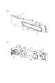
- FIG. 1A and 1B are diagrams showing an embodiment of the present invention.
- Fig.1 (a) is a front view which shows the state fixed to the door of the vehicle.
- FIG. 1B is a sectional view taken along line 1B-1B of FIG. 2A and 2B are views showing the handle device.
- FIG. 2A is a perspective view seen from the front.
- FIG. 2B is a perspective view seen from the back side.
- 3 (a) and 3 (b) are diagrams showing the present invention.
- 3A is a cross-sectional view taken along line 3A-3A in FIG.
- FIG. 3B is a diagram showing the configuration of the link.
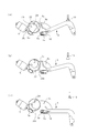
- FIGS. 4A to 4C are views showing the operation of the first link member.
- FIG. 4A is a diagram showing an initial rotation position.
- FIG. 4A is a diagram showing an initial rotation position.
- FIG. 4B is a diagram showing the operating rotation position.
- FIG. 4C is a diagram showing the use position.
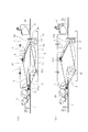
- FIGS. 5A and 5B are views showing the operation of the link member.
- FIG. 5A is a diagram showing a use state.
- FIG. 5B is a diagram showing a latch release state.
- 6 (a) and 6 (b) are diagrams showing another embodiment of the present invention.
- FIG. 6A is a diagram corresponding to FIG.
- FIG. 6B is a link configuration diagram of FIG.
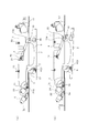
- FIGS. 7A and 7B are views showing the operation of the link member.
- FIG. 7A is a diagram showing a use state.
- FIG. 7B is a diagram illustrating a latch release state.
- FIG. 8 is a diagram showing an emergency state.
- the door handle device is formed by connecting an operation handle 2 to a handle base 1 via first and second link members 3 and 4, and is fixed to a vehicle door at the handle base 1.
- the operation handle 2 can move between an initial position shown in FIG. 1 and a use position shown in FIG. 5A.
- the surface of the operation handle 2 in the initial position is a door.
- the handle device of the flash surface specification is located on the same surface as the front surface (door outer panel 11) and is accommodated in the handle accommodating opening 11a provided in the door outer panel 11.
- the operation handle 2 is formed by connecting a back cover 2 b to the back surface of the handle body 2 a, and a front end portion of the handle body 2 a (refer to FIG. 1A in this specification). 1), the left side of FIG. 1B is the “front side” direction and the opposite direction is the “back side” direction.
- the rear link connecting portion 13 protrudes toward the back side.
- the handle recess 14 is formed between the front and rear link connecting portions 12 and 13 of the operation handle 2 so as to open to the back side, and the back cover 2b forms the surface of the handle recess 14. Further, the front and rear ends of the operation handle 2 project further forward and backward from the front and rear link connecting portions 12 and 13, and the projecting portion extending forward from the front link connecting portion 12 serves as a pressing operation portion 9, and the rear link connecting portion 13. The projecting portion from the rear to the rear is the cylinder shielding portion 15.
- the pressing operation part 9 is provided with a detection electrode 16a of a capacitance sensor, and a locking / unlocking switch part 16 is formed.
- the locking / unlocking switch part 16 is formed as a recess.
- An initial position return switch 17 having a detection electrode and a recess formed on the surface for informing the user of the detection electrode is disposed.
- a harness (not shown) connected to the detection electrode of the initial position return switch 17 is drawn out to the front end portion through a gap formed between the front and back covers 2b.
- the handle base 1 is disposed in contact with the back surface of the door outer panel 11, and the first link member 3 is connected to the front end portion and the second link member 4 is connected to the intermediate portion so as to be free to rotate. .
- the first link member 3 is pin-connected to the handle base 1 at the front end, and is counterclockwise in FIG. 4 by a first torsion spring 18 wound around the connection pin 3a. Be energized.
- the handle base 1 is formed with a first spring receiving wall 1a with which one leg of the first torsion spring 18 is pressed.
- first link member 3 is provided with a fan-shaped follower portion 3b at the front end portion, and an intermediate portion is bent in a V shape on the back surface side, and a bent portion is formed on the handle base 1. The rubber is pressed against the first stopper member 19 and held at the initial rotation position.
- the second link member 4 is initially in contact with a rubber second stopper member 20 having one end connected to the handle base 1 and the other end connected to the operation handle 2 and an intermediate portion formed on the handle base 1. Held in a rotational position.
- a second torsion spring 21 is wound around the rotation shaft 4a around the connection point between the second link member 4 and the handle base 1 to urge the second link member 4 counterclockwise in FIG.
- connection point between the first link member 3 and the handle base 1 is (P13)
- the connection point between the first link member 3 and the operation handle 2 is (P23)
- the second link is (P24)
- each connection point is a distance between the connection points (P13, P14). Is set to be equal to the interval between the connection points (P13, P24), and the interval between the connection points (P14, P24) is set to be equal to the interval between the connection points (P13, P23).
- the first and second links 3 ′ and 4 ′, the handle base link 1 ′, and the operation handle link 2 ′ constitute a four-joint parallel crank mechanism.
- the operation handle 2 has the first link member 3 pressed against the first stopper member 19 of the handle base 1 by the urging force of the first torsion spring 18, and the second link member 4 is moved to the second stopper member 20.
- the initial position is maintained in a state in which the occurrence of backlash due to the clearance at the connecting point is prevented.
- the handle base 1 is provided with a motor as the electric actuator 5 and a worm wheel 22 that meshes with a worm gear 5 a fixed to the rotating shaft of the motor 5.
- a cam member 23 having a cam surface 23 a is connected to the worm wheel 22 that is driven to rotate about the rotation shaft 22 a, and rotates on the same axis as the worm wheel 22.
- the cam member 23 is arranged in the moving region of the follower portion 3 b of the first link member 3 described above, and the motor 5 is moved from a state corresponding to the initial position of the operation handle 2 shown in FIG. When driven, it rotates clockwise in FIG.
- the rotation angle of the cam member 24 is detected by the two sensors 24 and 25, and the initial position corresponding state shown in FIG. 4A and the use position corresponding state shown in FIG.
- the operation handle 2 maintains a parallel posture from the initial position. While moving to the use position shown in FIG. In the use position, the handle recess 14 buried in the door in the initial position is exposed to the outside, and a sufficient handle space (S) is secured between the handle recess 14 and the door surface, After that, the latch of the door latch device can be released by putting the hand into the hand-holding space (S), pulling the operation handle 2 toward the outside of the door and moving it to the latch release position shown in FIG. .
- An appropriate stopper (not shown) that locks the operation handle 2 and the handle base 1 at the latch release position and restricts the drawer side stroke so that the operation handle 2 does not move further in the pulling direction from the latch release position. ) Is provided.
- the door latch device is unlatched by an electric actuator (not shown). That is, as shown in FIG. 5B, when the operation handle 2 is moved to the latch release position, the switch pushing portion 13 a protruding from the rear link connecting portion 13 of the operation handle 2 is attached to the handle base 1. The microswitch 26 is pushed, thereby driving an electric actuator for releasing the latch and releasing the latch of the door latch device.
- the door can be opened by pulling the operation handle 2 outward of the vehicle. Thereafter, when the pulling operation force to the operation handle 2 is released, the operation handle 2 is moved toward the initial position by the restoring force of the first and second torsion springs 18 and 21, and the follower surface 3c of the first link member 3 is moved. It stops at the use position where it abuts on the cam surface 23a.
- the initial position return switch 17 that has been immersed in the door at the initial position is exposed to the outside of the door.
- the switch 17 is touched, the electric actuator 5 is driven and the operation handle 2 returns to the initial position.
- the micro switch 26 When the operation handle 2 is moved from this state to the latch release position, the micro switch 26 is pressed and the latch release actuator is driven. By driving the actuator, the latch of the door latch device is released, and when the operation handle 2 is further pulled, the door can be opened.
- FIG. 6 shows another embodiment of the present invention.
- components that are substantially the same as those of the above-described embodiment are denoted by reference numerals in the drawing, and description thereof is omitted.
- a slide hole 10 is provided in which the pin 4b protruding from the operation handle 2 is loosely fitted in the second link member 4 of the above-described embodiment, and the first link member 3 and the operation handle 2 are connected.
- a torsion spring 6 for applying an urging force counterclockwise is wound around the operation handle 2 with the first link member 3 as a reference.
- the rest of the configuration is the same as that of the above-described embodiment.
- the link configuration in this example generally includes a sliding pair (S24) that can slide along the link 4 'at the pin connection point (P24) in FIG. 3B.
- the link mechanism of the added five clauses is provided, the position of the connection point (P13, P23, P14) is the same as that of the above-described embodiment, and only the position of the connection point (P24) is variable.
- the variable connecting point (P24) is one of the torsion springs 6, 18, 21 or the top of the slide hole 10 formed in a triangle by a combination of these restoring forces. Therefore, it operates with a substantially four-barrel parallel crank mechanism.
- the operation handle 2 When the operation handle 2 is further pulled out from the state toward the outside of the door, as shown in FIG. 7B, the operation handle 2 has the connection point (P23) with the first link member 3 as a rotation center as shown in FIG. Rotate clockwise in b). This posture corresponds to the latch release position of the above-described embodiment.
- the switch pushing portion 13a of the operation handle 2 pushes the micro switch 26 of the handle base 1, thereby driving the latch release electric actuator and releasing the latch of the door latch device. .
- the play formed between the slide hole 10 and the pin 4b causes the connection point (P23) to the first link member 3 as shown in FIG. 8 when the operation handle 2 is in the initial position. ) As the center of rotation, it is possible to shift to the emergency operation position rotated clockwise in FIG.
- the movement to the emergency operation position is performed by pushing the pressing operation portion 9 into the door, and the cylinder shielding portion 15 of the operation handle 2 is lifted from the door surface at the emergency operation position. As a result, the cylinder shielding portion 15 and the door are moved. A gap is formed between the surface.
- the cylinder lock 8 described above is arranged at a position where the unlocking key 7 can be inserted using the gap formed at the emergency operation position, and the user moves the operation handle 2 to the emergency operation position.
- the cylinder lock 8 can be operated by inserting the unlock key 7 into the cylinder lock 8 from the direction indicated by the arrow in FIG.
- the door handle is latched by operating the cylinder lock 8 using the unlock key 7 after manually moving the operation handle 2 to the emergency operation position.
- the device shifts to the unlocked state, and thereafter, the door can be opened by performing the same operation as the normal operation.
- the positions of the connecting pins of the links 1 ′, 2 ′, 3 ′, 4 ′ are arranged at positions that constitute the parallel crank mechanism, and the sliding amount in the sliding pair is set small.
- the sliding amount in the sliding pair is set small.
- the links 1 ′, 2 ′, 3 are not linked to the operation handle in the middle of the movement from the initial position to the use position so that the operation handle is parallel at the two positions of the initial position and the use position. It is also possible to appropriately set the relationship between the position of “4” and the link length.
Landscapes
- Lock And Its Accessories (AREA)
Abstract
Cette invention concerne un dispositif de poignée de portière pour véhicules, dans lequel une poignée d'actionnement est reliée à une base de poignée de façon à pouvoir faire saillie d'une position initiale à une position d'utilisation. Le dispositif de poignée comprend : des premier et second éléments de liaison qui sont situés à une certaine distance l'un de l'autre et qui sont chacun reliés de façon rotative à la base de poignée par une broche ; et un actionneur électrique qui entraîne en rotation le premier élément de liaison. La poignée d'actionnement est reliée de manière rotative aux extrémités des premier et second éléments de liaison, et la base de poignée, les premier et second éléments de liaison, et la poignée d'actionnement forment un mécanisme de liaison qui, lorsque la poignée d'actionnement est en position d'utilisation, maintient une attitude parallèle à la position initiale.
Priority Applications (3)
| Application Number | Priority Date | Filing Date | Title |
|---|---|---|---|
| EP19764655.7A EP3763904B1 (fr) | 2018-03-09 | 2019-02-27 | Dispositif de poignée de portière pour véhicules |
| CN201980018410.XA CN111836941B (zh) | 2018-03-09 | 2019-02-27 | 用于车辆的门把手装置 |
| US17/007,954 US11939799B2 (en) | 2018-03-09 | 2020-08-31 | Door handle device for vehicle |
Applications Claiming Priority (2)
| Application Number | Priority Date | Filing Date | Title |
|---|---|---|---|
| JP2018042785A JP6957390B2 (ja) | 2018-03-09 | 2018-03-09 | 車両のドアハンドル装置 |
| JP2018-042785 | 2018-03-09 |
Related Child Applications (1)
| Application Number | Title | Priority Date | Filing Date |
|---|---|---|---|
| US17/007,954 Continuation US11939799B2 (en) | 2018-03-09 | 2020-08-31 | Door handle device for vehicle |
Publications (1)
| Publication Number | Publication Date |
|---|---|
| WO2019172057A1 true WO2019172057A1 (fr) | 2019-09-12 |
Family
ID=67847135
Family Applications (1)
| Application Number | Title | Priority Date | Filing Date |
|---|---|---|---|
| PCT/JP2019/007715 Ceased WO2019172057A1 (fr) | 2018-03-09 | 2019-02-27 | Dispositif de poignée de portière pour véhicules |
Country Status (5)
| Country | Link |
|---|---|
| US (1) | US11939799B2 (fr) |
| EP (1) | EP3763904B1 (fr) |
| JP (2) | JP6957390B2 (fr) |
| CN (1) | CN111836941B (fr) |
| WO (1) | WO2019172057A1 (fr) |
Cited By (6)
| Publication number | Priority date | Publication date | Assignee | Title |
|---|---|---|---|---|
| US20200392771A1 (en) * | 2018-03-09 | 2020-12-17 | Alpha Corporation | Door handle device for vehicle |
| JP2021042576A (ja) * | 2019-09-11 | 2021-03-18 | 株式会社アルファ | 車両のハンドル装置 |
| EP3985214A1 (fr) * | 2020-10-16 | 2022-04-20 | HUF Hülsbeck & Fürst GmbH & Co. KG | Agencement de poignée de porte pour un véhicule automobile |
| US11454052B2 (en) * | 2015-06-16 | 2022-09-27 | U-Shin Italia S.P.A. | Handle for a vehicle door |
| GB2611814A (en) * | 2021-10-18 | 2023-04-19 | Jaguar Land Rover Ltd | Handle assembly |
| US12473759B2 (en) * | 2020-12-23 | 2025-11-18 | Alpha Corporation | Handle device for vehicle |
Families Citing this family (24)
| Publication number | Priority date | Publication date | Assignee | Title |
|---|---|---|---|---|
| ES2928686T3 (es) * | 2017-05-16 | 2022-11-21 | U Shin Italia Spa | Dispositivo de desenclavamiento de una cerradura de puerta |
| DE102019100319A1 (de) * | 2019-01-08 | 2020-07-09 | Huf Hülsbeck & Fürst Gmbh & Co. Kg | Fahrzeugtürgriff |
| FR3098539B1 (fr) * | 2019-07-08 | 2022-01-07 | U Shin Italia Spa | Poignée d’ouvrant pour véhicule automobile |
| JP7515380B2 (ja) * | 2019-12-26 | 2024-07-12 | 株式会社ユーシン | ドアハンドル装置 |
| JP7567524B2 (ja) * | 2021-02-03 | 2024-10-16 | マツダ株式会社 | 車両のドアハンドル構造 |
| JP7567523B2 (ja) * | 2021-02-03 | 2024-10-16 | マツダ株式会社 | 車両のドアハンドル構造及びその組付け方法 |
| JP7563207B2 (ja) * | 2021-02-03 | 2024-10-08 | マツダ株式会社 | 車両のドアハンドル構造 |
| JP7602941B2 (ja) * | 2021-03-15 | 2024-12-19 | 株式会社ユーシン | ドアハンドル装置 |
| CN116357175A (zh) * | 2021-12-29 | 2023-06-30 | Sl株式会社 | 车辆用门把手组件 |
| KR20230113038A (ko) * | 2022-01-21 | 2023-07-28 | 현대자동차주식회사 | 차량 도어용 전동식 래치의 제어방법 |
| EP4234858B1 (fr) * | 2022-02-23 | 2025-04-09 | Minebea AccessSolutions Italia S.p.A. | Ensemble poignée de porte de véhicule |
| ES3022683T3 (en) * | 2022-02-23 | 2025-05-28 | Minebea Accesssolutions Italia S P A | Vehicle door handle assembly |
| EP4249714B1 (fr) * | 2022-03-23 | 2025-10-08 | Minebea AccessSolutions Italia S.p.A. | Ensemble poignée de porte de véhicule |
| EP4261373A1 (fr) * | 2022-04-13 | 2023-10-18 | U-Shin Italia S.p.A. | Ensemble poignée de porte de véhicule |
| CN114856334B (zh) * | 2022-07-04 | 2022-09-20 | 宁波华翔汽车饰件有限公司 | 隐藏式门把手及车辆 |
| EP4306750A1 (fr) * | 2022-07-15 | 2024-01-17 | U-Shin Italia S.p.A. | Ensemble poignée de porte de véhicule |
| JP2024030532A (ja) * | 2022-08-24 | 2024-03-07 | ミネベアミツミ株式会社 | ドアラッチ装置 |
| CN115419333B (zh) * | 2022-09-09 | 2025-10-24 | 伟速达(中国)汽车安全系统有限公司 | 平出隐藏式汽车外门把手 |
| EP4353931A1 (fr) * | 2022-10-14 | 2024-04-17 | Minebea AccessSolutions Italia S.p.A. | Ensemble poignée de porte de véhicule avec un amortisseur |
| DE102022130600A1 (de) * | 2022-11-18 | 2024-05-23 | Huf Hülsbeck & Fürst Gmbh & Co. Kg | Griffanordnung eines Kraftfahrzeugs |
| EP4407128A1 (fr) * | 2023-01-27 | 2024-07-31 | Minebea AccessSolutions Italia S.p.A. | Ensemble poignée de porte de véhicule électrique |
| DE102024102885A1 (de) * | 2023-02-13 | 2024-08-14 | Illinois Tool Works Inc. | Türgriffanordnung |
| CN116575811A (zh) * | 2023-06-19 | 2023-08-11 | 烟台霍富汽车锁有限公司 | 一种隐藏式车门把手破冰机构 |
| WO2025210748A1 (fr) * | 2024-04-02 | 2025-10-09 | 日産自動車株式会社 | Poignée de porte rétractable pour véhicule |
Citations (4)
| Publication number | Priority date | Publication date | Assignee | Title |
|---|---|---|---|---|
| US20130241215A1 (en) * | 2010-01-15 | 2013-09-19 | Jaguar Cars Ltd | Retractable handle for a door or the like |
| US20150315826A1 (en) * | 2014-05-05 | 2015-11-05 | GM Global Technology Operations LLC | Flush door handle with shape memory alloy drive and heated handle to body seal |
| JP2015533964A (ja) | 2012-09-25 | 2015-11-26 | ジャガー・ランド・ローバー・リミテッドJaguar Land Rover Limited | 引込み式ハンドル構造 |
| JP2018042785A (ja) | 2016-09-15 | 2018-03-22 | 株式会社三共 | 遊技機 |
Family Cites Families (51)
| Publication number | Priority date | Publication date | Assignee | Title |
|---|---|---|---|---|
| DE19731325A1 (de) * | 1997-07-22 | 1999-01-28 | Bayerische Motoren Werke Ag | Griffanordnung für die Tür eines Fahrzeugs |
| DE102008019335A1 (de) * | 2007-04-18 | 2008-10-23 | Friedr. Fingscheidt Gmbh | Türgriff mit Betätigungseinrichtung zur Anordnung in einem Kraftfahrzeug |
| US8146393B2 (en) * | 2008-02-19 | 2012-04-03 | Kabushiki Kaisha Tokai Rika Denki Seisakusho | Vehicle door handle device |
| DE102009018803A1 (de) * | 2009-04-24 | 2010-10-28 | Daimler Ag | Griffeinrichtung für einen Kraftwagen |
| DE102011001001A1 (de) * | 2010-12-27 | 2012-06-28 | Huf Hülsbeck & Fürst Gmbh & Co. Kg | Türaußengriffvorrichtung eines Kraftfahrzeugs |
| US9151089B2 (en) * | 2011-09-26 | 2015-10-06 | Tesla Motors, Inc. | Controller apparatus and sensors for a vehicle door handle |
| US8690204B2 (en) | 2011-11-23 | 2014-04-08 | GM Global Technology Operations LLC | Flush door handle assembly with normal deployment |
| DE102013112706A1 (de) * | 2013-11-18 | 2015-05-21 | Illinois Tool Works Inc. | System aus einem Türgriff und einer Betätigungseinrichtung für den Türgriff |
| EP3020897A1 (fr) * | 2014-11-12 | 2016-05-18 | Illinois Tool Works Inc. | Dispositif à bouton poussoir avec commande de pression avec cinématique améliorée pour application dans un véhicule |
| WO2016113339A1 (fr) * | 2015-01-16 | 2016-07-21 | Bos Gmbh & Co. Kg | Portière de véhicule automobile et système de poignée de portière correspondant |
| KR101637820B1 (ko) * | 2015-03-24 | 2016-07-07 | 현대자동차주식회사 | 차량용 리트랙터블 핸들 장치 |
| GB2536669B (en) * | 2015-03-25 | 2018-03-21 | Jaguar Land Rover Ltd | Rectractable handle arrangement |
| GB2536670B (en) * | 2015-03-25 | 2018-04-04 | Jaguar Land Rover Ltd | Rectractable handle arrangement with means to prevent lateral play |
| EP3103946A1 (fr) * | 2015-06-08 | 2016-12-14 | Illinois Tool Works Inc. | Actionneur de serrure de porte comprenant plusieurs types d'actionnement de serrure de porte |
| CN108474221B (zh) * | 2015-10-21 | 2021-03-09 | 伊利诺斯工具制品有限公司 | 车辆的门把手 |
| DE102016104372A1 (de) | 2016-03-10 | 2017-09-14 | Huf Hülsbeck & Fürst Gmbh & Co. Kg | Türgriffanordnung eines Kraftfahrzeugs |
| DE102016112689A1 (de) * | 2016-07-11 | 2018-01-11 | Huf Hülsbeck & Fürst Gmbh & Co. Kg | Griffvorrichtung mit einem flächenbündigen Griff |
| KR101875658B1 (ko) * | 2016-08-24 | 2018-07-06 | 현대자동차 주식회사 | 차량용 출몰형 아웃사이드 도어 핸들 조립체 |
| DE102016119423A1 (de) * | 2016-10-12 | 2018-04-12 | Huf Hülsbeck & Fürst Gmbh & Co. Kg | Griffvorrichtung |
| ES2928686T3 (es) * | 2017-05-16 | 2022-11-21 | U Shin Italia Spa | Dispositivo de desenclavamiento de una cerradura de puerta |
| EP3404177B1 (fr) * | 2017-05-16 | 2019-11-27 | U-Shin Italia S.p.A. | Commande de poignée affleurante |
| DE102017118695A1 (de) * | 2017-07-13 | 2019-01-17 | Huf Hülsbeck & Fürst Gmbh & Co. Kg | Türgriffanordnung für ein Kraftfahrzeug |
| DE102017010196B3 (de) * | 2017-10-30 | 2019-04-25 | Daimler Ag | Griffvorrichtung für eine Kraftfahrzeugtür |
| DE102017130030A1 (de) * | 2017-12-14 | 2019-06-19 | Huf Hülsbeck & Fürst Gmbh & Co. Kg | Türgriffanordnung einer Fahrzeugtür |
| DE102017130029A1 (de) * | 2017-12-14 | 2019-06-19 | Huf Hülsbeck & Fürst Gmbh & Co. Kg | Türgriffanordnung einer Fahrzeugtür |
| DE102017130031A1 (de) * | 2017-12-14 | 2019-06-19 | Huf Hülsbeck & Fürst Gmbh & Co. Kg | Türgriffanordnung einer Fahrzeugtür |
| KR102006288B1 (ko) * | 2017-12-15 | 2019-08-06 | 평화정공(주) | 자동차 도어용 핸들장치 |
| DE102018101040A1 (de) * | 2018-01-18 | 2019-07-18 | Huf Hülsbeck & Fürst Gmbh & Co. Kg | Kraftfahrzeuggriffanordnung und Verfahren zum Betrieb einer solchen Kraftfahrzeuggriffanordnung |
| US11332963B2 (en) * | 2018-01-18 | 2022-05-17 | Illinois Tool Works Inc. | Retractable arrangement for actuating a vehicle door with improved ice-breaking function |
| CN108193961A (zh) * | 2018-02-05 | 2018-06-22 | 东方久乐汽车电子(上海)股份有限公司 | 一种改进型隐藏式汽车门把手机构 |
| JP6957390B2 (ja) * | 2018-03-09 | 2021-11-02 | 株式会社アルファ | 車両のドアハンドル装置 |
| FR3078990B1 (fr) * | 2018-03-16 | 2021-01-15 | Mgi Coutier Espana Sl | Commande d'ouverture a remontage mecanique |
| CN108374615B (zh) * | 2018-05-11 | 2023-07-28 | 中山市澳多电子科技有限公司 | 一种电动门把手 |
| JP7022657B2 (ja) * | 2018-06-08 | 2022-02-18 | 株式会社アルファ | 車両のアウトサイドハンドル装置 |
| EP3581742B1 (fr) * | 2018-06-11 | 2020-05-27 | U-Shin Italia S.p.A. | Poignée de porte affleurante et son procédé de fonctionnement |
| KR102540440B1 (ko) * | 2018-06-15 | 2023-06-05 | 현대자동차 주식회사 | 차량용 출몰형 아웃사이드 도어 핸들 조립체 |
| KR102621229B1 (ko) * | 2018-08-31 | 2024-01-04 | 현대자동차 주식회사 | 차량용 출몰형 아웃사이드 도어 핸들 조립체 |
| DE102018121432A1 (de) * | 2018-09-03 | 2020-03-05 | Huf Hülsbeck & Fürst Gmbh & Co. Kg | Türgriffanordnung für ein Kraftfahrzeug |
| US11680432B2 (en) * | 2018-10-02 | 2023-06-20 | Magna Mirrors Of America, Inc. | Flush door handle for vehicle |
| KR102104888B1 (ko) * | 2019-01-24 | 2020-04-27 | 주식회사 프라코 | 차량용 오토 플러쉬 아웃사이드 도어 핸들 조립체 |
| JP7313996B2 (ja) * | 2019-09-11 | 2023-07-25 | 株式会社アルファ | 車両のハンドル装置 |
| JP7313995B2 (ja) * | 2019-09-11 | 2023-07-25 | 株式会社アルファ | 車両のハンドル装置 |
| JP7271375B2 (ja) * | 2019-09-11 | 2023-05-11 | 株式会社アルファ | 車両のハンドル装置 |
| CN112780134B (zh) * | 2019-11-11 | 2023-10-13 | 伊利诺斯工具制品有限公司 | 一种用于车辆的门的把手组件 |
| CN111593977B (zh) * | 2020-05-26 | 2025-02-21 | 宁波华德汽车零部件有限公司 | 一种车用电动伸缩把手 |
| GB2595913B (en) * | 2020-06-11 | 2023-07-05 | Jaguar Land Rover Ltd | Retractable handle arrangement and controller for controlling the same |
| KR102751308B1 (ko) * | 2020-08-28 | 2025-01-09 | 현대자동차주식회사 | 차량도어핸들조립체 |
| DE102021209082A1 (de) * | 2021-05-12 | 2022-11-17 | Witte Automotive Gmbh | Türgriffanordnung und Fahrzeugtür |
| CN116357175A (zh) * | 2021-12-29 | 2023-06-30 | Sl株式会社 | 车辆用门把手组件 |
| CN114737833B (zh) * | 2022-04-21 | 2023-09-19 | 湖北航宇精工科技有限公司 | 一种隐藏式汽车外把手结构 |
| CN115354927B (zh) * | 2022-09-08 | 2026-01-09 | 惠州市华阳多媒体电子有限公司 | 一种防失效隐藏式车门把手 |
-
2018
- 2018-03-09 JP JP2018042785A patent/JP6957390B2/ja active Active
-
2019
- 2019-02-27 EP EP19764655.7A patent/EP3763904B1/fr active Active
- 2019-02-27 CN CN201980018410.XA patent/CN111836941B/zh active Active
- 2019-02-27 WO PCT/JP2019/007715 patent/WO2019172057A1/fr not_active Ceased
-
2020
- 2020-08-31 US US17/007,954 patent/US11939799B2/en active Active
-
2021
- 2021-10-06 JP JP2021164579A patent/JP7216787B2/ja active Active
Patent Citations (4)
| Publication number | Priority date | Publication date | Assignee | Title |
|---|---|---|---|---|
| US20130241215A1 (en) * | 2010-01-15 | 2013-09-19 | Jaguar Cars Ltd | Retractable handle for a door or the like |
| JP2015533964A (ja) | 2012-09-25 | 2015-11-26 | ジャガー・ランド・ローバー・リミテッドJaguar Land Rover Limited | 引込み式ハンドル構造 |
| US20150315826A1 (en) * | 2014-05-05 | 2015-11-05 | GM Global Technology Operations LLC | Flush door handle with shape memory alloy drive and heated handle to body seal |
| JP2018042785A (ja) | 2016-09-15 | 2018-03-22 | 株式会社三共 | 遊技機 |
Non-Patent Citations (1)
| Title |
|---|
| See also references of EP3763904A4 |
Cited By (10)
| Publication number | Priority date | Publication date | Assignee | Title |
|---|---|---|---|---|
| US11454052B2 (en) * | 2015-06-16 | 2022-09-27 | U-Shin Italia S.P.A. | Handle for a vehicle door |
| US20200392771A1 (en) * | 2018-03-09 | 2020-12-17 | Alpha Corporation | Door handle device for vehicle |
| US11939799B2 (en) * | 2018-03-09 | 2024-03-26 | Alpha Corporation | Door handle device for vehicle |
| JP2021042576A (ja) * | 2019-09-11 | 2021-03-18 | 株式会社アルファ | 車両のハンドル装置 |
| WO2021049214A1 (fr) * | 2019-09-11 | 2021-03-18 | 株式会社アルファ | Dispositif de poignée de véhicule |
| JP7271375B2 (ja) | 2019-09-11 | 2023-05-11 | 株式会社アルファ | 車両のハンドル装置 |
| EP3985214A1 (fr) * | 2020-10-16 | 2022-04-20 | HUF Hülsbeck & Fürst GmbH & Co. KG | Agencement de poignée de porte pour un véhicule automobile |
| US12473759B2 (en) * | 2020-12-23 | 2025-11-18 | Alpha Corporation | Handle device for vehicle |
| GB2611814A (en) * | 2021-10-18 | 2023-04-19 | Jaguar Land Rover Ltd | Handle assembly |
| GB2611814B (en) * | 2021-10-18 | 2024-04-17 | Jaguar Land Rover Ltd | Handle assembly |
Also Published As
| Publication number | Publication date |
|---|---|
| JP7216787B2 (ja) | 2023-02-01 |
| EP3763904A1 (fr) | 2021-01-13 |
| CN111836941A (zh) | 2020-10-27 |
| EP3763904B1 (fr) | 2023-04-19 |
| JP6957390B2 (ja) | 2021-11-02 |
| US20200392771A1 (en) | 2020-12-17 |
| US11939799B2 (en) | 2024-03-26 |
| JP2019157424A (ja) | 2019-09-19 |
| JP2022003214A (ja) | 2022-01-11 |
| CN111836941B (zh) | 2026-03-24 |
| EP3763904A4 (fr) | 2021-11-24 |
Similar Documents
| Publication | Publication Date | Title |
|---|---|---|
| WO2019172057A1 (fr) | Dispositif de poignée de portière pour véhicules | |
| JP4972803B2 (ja) | 車両用ドアラッチ装置 | |
| KR101637820B1 (ko) | 차량용 리트랙터블 핸들 장치 | |
| US9322204B2 (en) | Door actuating apparatus | |
| JP5288314B2 (ja) | 車両用ドアラッチ装置 | |
| US20110309640A1 (en) | Lock device | |
| JP7127242B2 (ja) | 自動車用ドアラッチ装置 | |
| JP5303902B2 (ja) | 車両ドアロック装置 | |
| KR101918367B1 (ko) | 차량용 트렁크 래치 모듈 | |
| JP6697367B2 (ja) | ドアロック装置 | |
| JP7064907B2 (ja) | 車両のドアハンドル装置 | |
| WO2021049213A1 (fr) | Dispositif de poignée pour véhicule | |
| JP2016199937A (ja) | 車両のハンドル装置 | |
| CN114673413A (zh) | 可伸缩的外侧车门把手组件 | |
| KR102663985B1 (ko) | 차량용 출몰형 아웃사이드 도어 핸들 조립체 | |
| JP5213190B2 (ja) | 車両用ドアラッチ装置 | |
| JP7290098B2 (ja) | 車両用ドアロック装置 | |
| JP5495166B2 (ja) | 車両用ドアラッチ装置 | |
| CN103415669B (zh) | 用于车门锁定系统的控制设备 | |
| KR101651677B1 (ko) | 차량용 수납상자 잠금 시스템 | |
| JP2024021300A (ja) | 車両用のドアハンドル装置 | |
| JPS6393980A (ja) | ドアロツク装置 | |
| KR100872689B1 (ko) | 자동차용 도어 록킹장치의 스트라이커 조립체 | |
| JP2023167812A (ja) | 車両用のドアロック装置 | |
| JP2005120682A (ja) | 車両用ドアロック装置 |
Legal Events
| Date | Code | Title | Description |
|---|---|---|---|
| 121 | Ep: the epo has been informed by wipo that ep was designated in this application |
Ref document number: 19764655 Country of ref document: EP Kind code of ref document: A1 |
|
| NENP | Non-entry into the national phase |
Ref country code: DE |
|
| WWE | Wipo information: entry into national phase |
Ref document number: 2019764655 Country of ref document: EP |