WO2019176351A1 - Casque - Google Patents
Casque Download PDFInfo
- Publication number
- WO2019176351A1 WO2019176351A1 PCT/JP2019/003153 JP2019003153W WO2019176351A1 WO 2019176351 A1 WO2019176351 A1 WO 2019176351A1 JP 2019003153 W JP2019003153 W JP 2019003153W WO 2019176351 A1 WO2019176351 A1 WO 2019176351A1
- Authority
- WO
- WIPO (PCT)
- Prior art keywords
- liner
- shell
- pieces
- helmet
- wearer
- Prior art date
- Legal status (The legal status is an assumption and is not a legal conclusion. Google has not performed a legal analysis and makes no representation as to the accuracy of the status listed.)
- Ceased
Links
Images




Classifications
-
- A—HUMAN NECESSITIES
- A42—HEADWEAR
- A42B—HATS; HEAD COVERINGS
- A42B3/00—Helmets; Helmet covers ; Other protective head coverings
- A42B3/04—Parts, details or accessories of helmets
- A42B3/10—Linings
- A42B3/12—Cushioning devices
Definitions
- the present invention relates to a helmet worn when riding a vehicle or performing sports.
- a structure having a shell that covers the wearer's head and forms the outer shape of the helmet and a cushioning liner disposed between the wearer's head and the inside of the shell is known. Yes.
- a helmet in which the liner is divided into a plurality of liner pieces to facilitate the arrangement of the liner in the shell see, for example, Patent Document 1).
- the joining surfaces of the liner pieces are bonded together, or the liner piece and the shell inner surface are bonded, It becomes necessary to prevent escape of the liner (a combination of a plurality of liner pieces).
- a border material such as tape along the periphery of the opening of the covering opening (opening for the wearer's head) provided in the shell.
- segmentation structure of a liner when it sets so that the joining line of a liner piece may extend in the front-back direction of a shell, it means that the liner is what is called “vertically divided" with respect to a wearer's head. For this reason, there has been a concern that the impact absorbing power may be reduced with respect to the impact received by the wearer's frontal and occipital heads.
- the present invention has been made in view of the above circumstances, and enables the placement of the liner in the shell to be easily and reliably performed without using an adhesive or the like, thereby increasing the production efficiency and reducing the cost.
- An object is to provide a helmet that can realize the above.
- the helmet according to the present invention includes a shell that covers the wearer's head and forms a helmet outer shape, and a cushioning liner that is disposed between the wearer's head and the inside of the shell.
- the liner has a plurality of liner pieces arranged in a lining on the inner side of the shell by combining the liner pieces in the front-rear direction or the left-right direction of the shell.
- the aperture is formed as a narrowed edge portion so as to prevent the escape of the piece continuous end generated when the liner pieces are combined.
- the aperture edge has a bent shape that protrudes inwardly in the entire circumference or part of the circumferential direction of the covering mouth and engages with the piece-connected end. It is possible to set the joining line when combining the liner pieces so as to extend in the left-right direction or the front-rear direction of the shell.
- the liner piece is formed of a combination of three or more pieces in the front-rear direction or the left-right direction of the shell, and in the comparison of the elasticity expressed when strengthening the curved curve along the wearer's head shape,
- the liner pieces arranged between the two ends of the combination position may be formed of a highly elastic material rather than the liner pieces arranged between the two ends.
- the liner can be arranged in the shell easily and reliably without using an adhesive, and the manufacturing efficiency can be increased and the cost can be reduced.
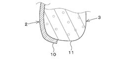
- FIG. 4 is a sectional view taken along line AA in FIG. 3. It is the B section enlarged view of FIG. BRIEF DESCRIPTION OF THE DRAWINGS
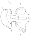
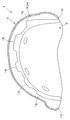
- FIG. 1 is a bottom view (a plan view of a cover opening) showing a first embodiment of a helmet according to the present invention. It is the sectional side view which showed 1st Embodiment of the helmet which concerns on this invention in the decomposition
- FIG. 3 is a cross-sectional view of the helmet according to the second embodiment of the present invention, viewed from the same viewpoint as FIG. 2 for easy comparison with the first embodiment.
- FIG. 3 is a cross-sectional view of the helmet according to the third embodiment of the present invention, viewed from the same viewpoint as FIG. 2 for easy comparison with the first embodiment. It is the bottom view (figure which looked at the cover mouth in plane) which showed a 4th embodiment of the helmet concerning the present invention. It is CC sectional view taken on the line of FIG.
- the helmet 1 includes a shell 2 that covers the wearer's head and forms the outer shape of the helmet, and a cushioning liner 3 that is disposed between the wearer's head and the inside of the shell 2.
- the outer shape of the helmet formed by the shell 2 is not particularly limited, and may be a half type as exemplified in the first embodiment, a jet type, a full face type, or the like.
- the shell 2 is provided with a covering opening 5 for covering or taking off the head of the wearer.
- the liner 3 is held inside the shell 2 in a lining shape.
- “hold” does not mean that the liner 3 is fixed to the shell 2 by a fixing means such as adhesion, but the fitting relationship (engagement action) of the liner 3 with the shell 2 is the main structure, and a state in which it cannot escape is generated. Say what you let me. However, the adoption of the fixing means is not excluded as long as it has this fitting relationship.
- the liner 3 is formed with a hemispherical recess that conforms to the shape of the head of the wearer in an arrangement that is inside the cover 5 of the shell 2 so that a proper wearing feeling can be obtained for the wearer. It has become.
- the liner 3 is divided into a plurality of (three pieces in the first embodiment) liner pieces 3 a, 3 b, 3 c, and these liner pieces 3 a, 3 b, 3 c are combined while corresponding to the shape in the shell 2.
- the entire shape is configured.
- each liner piece 3a, 3b, 3c may be either the front-rear direction or the left-right direction of the shell 2.
- the front-rear direction of the shell 2 is used. Therefore, the joining line formed when the liner pieces 3 a, 3 b, 3 c are combined is oriented in the left-right direction of the shell 2.
- what is combined in the left-right direction of the shell 2 (where the joining line is oriented in the front-rear direction of the shell 2) will be described later as a fourth embodiment.
- the engagement structure employed to hold the liner 3 on the inner side of the shell 2 has a throttle edge 10 formed in the cover port 5 of the shell 2 as a main part.
- the aperture edge 10 is formed by bending the skirt of the shell 2 (the opening edge of the cover 5) inwardly in the entire circumference or in a part in the circumferential direction. Yes.
- the piece continuous end 11 (the wearer's end) generated when the liner pieces 3 a, 3 b, 3 c are combined in the shell 2. It is an opening peripheral part of the hemispherical concave portion of the liner 3 for taking in and out the head and is also the thickness of the liner 3. Refer to FIG. Therefore, the liner 3 is prevented from escaping from the inside of the shell 2.
- the liner piece 3a that is arranged on the front side of the shell 2 is fitted, and the liner piece 3c that is arranged on the rear side of the shell 2 is fitted. Then, a liner piece 3b having a central arrangement is fitted between the front and rear liner pieces 3a and 3c. Any of the order of the front and rear liner pieces 3a, 3c may be first, or may be simultaneous.
- the front and rear liner pieces 3a, 3c are pressed so as to be distributed forward and backward, respectively, and as a result, the liner 3 (liner pieces 3a, 3b, 3c) As a whole, it becomes impossible to move in the front-rear direction. Therefore, the escape of the liner 3 from the covered edge portion 10 of the shell 2 is prevented.
- the liner 3 as a whole combining the liner pieces 3a, 3b, and 3c has a size that fits into the shell 2 without gaps or is slightly larger than that, so that the liner 3 fitted into the shell 2 is inserted. It goes without saying that misalignment and rattling can be prevented. Therefore, it is not necessary to bond the liner 3 to the shell 2.
- engagement protrusions 12a, 12b, 12c are provided on the front surface having a half-moon shape with respect to the centrally arranged liner piece 3b, and the rear surface is also engaged in the same manner.
- Protrusions 13a, 13b, and 13c are provided, and all the surfaces are uneven in the left-right direction.
- the meshing protrusions 12a to 12c and 13a to 13c of the centrally arranged liner piece 3b are provided on the rear surface of the frontly arranged liner piece 3a and the front surface of the rearly arranged liner piece 3c.
- Engaging protrusions 14a to 14b and 15a to 15b are provided so as to be engaged with each other, and are uneven in the left-right direction as in the case of the liner piece 3b arranged at the center.
- the centrally arranged liner piece is also applied to the meshing projections 14a to 14b provided on the rear surface of the liner piece 3a arranged on the front side and the meshing projections 15a to 15b provided on the front surface of the liner piece 3c arranged on the rear side.
- An inclination (in the same direction) may be provided so as to correspond to the engaging protrusions 12b and 13b at the left and right center of 3b. Of course, it may not be provided. In some cases, in order to increase the wedge effect, an inclination that reverses the inclination direction may be provided.
- the liner 3 is preferably formed of a resilient material such as polystyrene foam.
- a resilient material such as polystyrene foam.
- both ends at the combination position of the three pieces (the liner piece 3a arranged at the front side and the liner piece 3c arranged at the rear side) ) Between them (in the case of 3 pieces, the centrally arranged liner piece 3b) may be formed of a highly elastic material.
- the front and rear liner pieces 3a and 3c are made of EPS (bead method foamed polystyrene), and the centrally arranged liner piece 3b is made of EPP (bead method foamed polypropylene) which is more elastic than EPS.
- all the liner pieces 3a, 3b, 3c may be formed of EPS or EPP. This makes it easy to combine the liner pieces 3a, 3b, and 3c in the shell 2, and the front-rear pressing force to the front and rear liner pieces 3a and 3c generated by the centrally arranged liner piece 3b.
- the advantage that flexibility can be given and it can utilize as a position shift prevention effect will be acquired.
- FIG. 6 shows a second embodiment of the helmet 1 according to the present invention.
- the difference between the second embodiment and the first embodiment is that the amount of the diaphragm edge 10 employed in the shell 2 is projected from the bottom of the shell 2 to the inside of the cover port 5 (the size of the bent structure). ) Is larger.
- the amount of overhang is larger than that of the aperture edge 10 of the first embodiment, the amount of engagement of the liner 3 with the piece continuous end 11 is also large (the amount is approximately comparable to the thickness of the liner 3 at the maximum). ). By doing in this way, the holding
- Other configurations and operational effects are the same as those of the first embodiment.
- FIG. 7 shows a third embodiment of the helmet 1 according to the present invention.
- the third embodiment is different from the first embodiment and the second embodiment in that the diameter of the diaphragm edge 10 employed in the shell 2 decreases as the skirt of the shell 2 approaches the cover port 5 over the entire circumference. It is in the point which narrows down so that the outer diameter is reduced.
- it is not always necessary to engage the diaphragm edge portion 10 with the piece continuous end 11 of the liner 3.
- the inner surface of the shell 2 wraps in a wide range with respect to the outer surface of the liner 3 without being engaged with the piece end 11 of the liner 3. There will be no escape from the inside, no misalignment or rattling.
- the helmet 1 of the fourth embodiment is most different from the first embodiment in that the dividing direction (combining direction) of the liner pieces 3d and 3e constituting the liner 3 is the left-right direction of the shell 2.
- a joining line when combining the liner pieces 3d and 3e is generated in a direction extending in the front-rear direction of the shell 2.
- the liner 3 is so-called “vertically divided” with respect to the wearer's head.
- the left-side arranged liner piece 3d is provided with a stepped portion 16a protruding toward the right-side arranged liner piece 3e, and the right-side arranged liner piece 3e is provided with a left-side arranged liner.
- An overhang portion 16b that engages with the step portion 16a of the piece 3d is provided.
- the left and right liner pieces 3d and 3e are not separated so as to form a vertically cracked gap at the center of the left and right. Can be sufficiently absorbed.
- the advantage that the left and right liner pieces 3d and 3e are not connected and fixed in the left-right direction can be flexibly adapted to different head sizes for each wearer (becomes a free size).
- the stepped portion 16a is provided with meshing projections 18 in a gear-like arrangement along the front-rear direction of the shell 2, and the overhang portion 16b has A meshing projection (not shown) that meshes with these meshing projections 18 is provided. Therefore, when the liner pieces 3d and 3e are combined in the shell 2, the meshing protrusions are engaged with each other, and the alignment of the liner pieces 3d and 3e in the front-rear direction is uniquely restricted. Of course, it is also possible to increase the joining force of the liner pieces 3d and 3e, and to prevent the positional deviation and backlash of the liner 3 in the shell 2.
- the fourth embodiment is also exemplified in the first embodiment (see FIG. 2), the second embodiment (see FIG. 6), the third embodiment (see FIG. 7), etc. with respect to the covering port 5 of the shell 2.
- the aperture edge 10 is provided. Therefore, also in the fourth embodiment, the effects described in the first to third embodiments can be obtained in the same manner, and this makes it easy to dispose the liner 3 in the shell 2 without using an adhesive or the like. In addition, it is possible to reliably perform the operation and effect of the helmet 1 according to the present invention, which can increase the production efficiency and realize the cost reduction.
- the present invention is not limited to the above-described embodiment, and can be appropriately changed according to the embodiment.
- the centrally arranged liner piece 3b may be integrated with the front arranged liner piece 3a, or may be integrated with the rear arranged liner piece 3c.
- the liner 3 can be divided into three or more pieces in the left-right direction.
- the dividing direction (combining direction) of the liner pieces 3d and 3e constituting the liner 3 is the same as the left-right direction of the shell 2, but this case is also exemplified in the first embodiment.
- the number of divisions may be three or more. That is, the liner pieces 3d and 3e can be used as both ends at the combination position of the three pieces, and an intermediate liner piece can be sandwiched between them.
Landscapes
- Helmets And Other Head Coverings (AREA)
Abstract
La présente invention vise à renforcer l'efficacité de fabrication et à réduire les coûts en permettant à une doublure d'être disposée très simplement et de manière sûre sur l'intérieur d'une coque sans utiliser d'adhésif ou similaire. À cet effet, un casque selon l'invention comprend : une coque (2) qui recouvre la tête d'un porteur et qui forme la forme extérieure d'un casque ; et une doublure d'amortissement (3) disposée entre la tête de l'utilisateur et l'intérieur de la coque (2). La doublure (3) est conçue sous la forme d'une doublure par combinaison d'une pluralité de pièces de doublure (3a, 3b, 3c) dans le sens avant-arrière ou dans le sens gauche-droite de la coque (2) ; et une ouverture d'enfilage (5), qui est destinée au porteur et ménagée dans la coque (2), est formée en tant que section de bord de contraction (10) ayant une ouverture réduite de façon à empêcher qu'une extrémité de liaison de pièces (11) ne s'échappe lors de la combinaison des pièces de doublure (3a, 3b, 3c) dans la coque (2).
Priority Applications (1)
| Application Number | Priority Date | Filing Date | Title |
|---|---|---|---|
| CN201980007855.8A CN111601526A (zh) | 2018-03-15 | 2019-01-30 | 头盔 |
Applications Claiming Priority (2)
| Application Number | Priority Date | Filing Date | Title |
|---|---|---|---|
| JP2018047961A JP2019157311A (ja) | 2018-03-15 | 2018-03-15 | ヘルメット |
| JP2018-047961 | 2018-03-15 |
Publications (1)
| Publication Number | Publication Date |
|---|---|
| WO2019176351A1 true WO2019176351A1 (fr) | 2019-09-19 |
Family
ID=67907564
Family Applications (1)
| Application Number | Title | Priority Date | Filing Date |
|---|---|---|---|
| PCT/JP2019/003153 Ceased WO2019176351A1 (fr) | 2018-03-15 | 2019-01-30 | Casque |
Country Status (4)
| Country | Link |
|---|---|
| JP (1) | JP2019157311A (fr) |
| CN (1) | CN111601526A (fr) |
| TW (1) | TW201938056A (fr) |
| WO (1) | WO2019176351A1 (fr) |
Citations (8)
| Publication number | Priority date | Publication date | Assignee | Title |
|---|---|---|---|---|
| JPH01132809A (ja) * | 1987-11-18 | 1989-05-25 | Yamaha Motor Co Ltd | ヘルメット |
| JPH0363532U (fr) * | 1990-08-24 | 1991-06-20 | ||
| JPH0654735U (ja) * | 1992-12-28 | 1994-07-26 | 東京シート株式会社 | 取外し式内装を備えたヘルメット |
| JPH0659432U (ja) * | 1993-01-19 | 1994-08-19 | オージーケー販売株式会社 | ヘルメットの換気構造 |
| JPH09105014A (ja) * | 1995-10-09 | 1997-04-22 | O G K Giken Kk | ヘルメット |
| JPH11256418A (ja) * | 1998-03-12 | 1999-09-21 | Free Ride:Kk | ヘルメットの衝撃吸収ライナ及びヘルメット |
| US20060112477A1 (en) * | 2002-08-08 | 2006-06-01 | Schneider Marc S | Energy absorbing sports helmet |
| US7140049B2 (en) * | 2004-08-03 | 2006-11-28 | Bell Sports, Inc. | Helmet protection system |
Family Cites Families (1)
| Publication number | Priority date | Publication date | Assignee | Title |
|---|---|---|---|---|
| JP2007009347A (ja) * | 2005-06-28 | 2007-01-18 | Ogk Kabuto:Kk | ヘルメット |
-
2018
- 2018-03-15 JP JP2018047961A patent/JP2019157311A/ja active Pending
-
2019
- 2019-01-30 WO PCT/JP2019/003153 patent/WO2019176351A1/fr not_active Ceased
- 2019-01-30 CN CN201980007855.8A patent/CN111601526A/zh active Pending
- 2019-02-14 TW TW108104872A patent/TW201938056A/zh unknown
Patent Citations (8)
| Publication number | Priority date | Publication date | Assignee | Title |
|---|---|---|---|---|
| JPH01132809A (ja) * | 1987-11-18 | 1989-05-25 | Yamaha Motor Co Ltd | ヘルメット |
| JPH0363532U (fr) * | 1990-08-24 | 1991-06-20 | ||
| JPH0654735U (ja) * | 1992-12-28 | 1994-07-26 | 東京シート株式会社 | 取外し式内装を備えたヘルメット |
| JPH0659432U (ja) * | 1993-01-19 | 1994-08-19 | オージーケー販売株式会社 | ヘルメットの換気構造 |
| JPH09105014A (ja) * | 1995-10-09 | 1997-04-22 | O G K Giken Kk | ヘルメット |
| JPH11256418A (ja) * | 1998-03-12 | 1999-09-21 | Free Ride:Kk | ヘルメットの衝撃吸収ライナ及びヘルメット |
| US20060112477A1 (en) * | 2002-08-08 | 2006-06-01 | Schneider Marc S | Energy absorbing sports helmet |
| US7140049B2 (en) * | 2004-08-03 | 2006-11-28 | Bell Sports, Inc. | Helmet protection system |
Also Published As
| Publication number | Publication date |
|---|---|
| TW201938056A (zh) | 2019-10-01 |
| JP2019157311A (ja) | 2019-09-19 |
| CN111601526A (zh) | 2020-08-28 |
Similar Documents
| Publication | Publication Date | Title |
|---|---|---|
| USD965909S1 (en) | Safety helmet | |
| CN111204370A (zh) | 方向盘 | |
| TWI488589B (zh) | Half-hooded helmet | |
| CN114728667B (zh) | 方向盘 | |
| WO2013018510A1 (fr) | Garniture de portière | |
| KR20130095678A (ko) | 폴딩 헬멧 | |
| EP0997080A2 (fr) | Casque du type dit intégral | |
| JP4946205B2 (ja) | ウォームホイール及びウォームギア | |
| US7707648B2 (en) | Helmet with visor | |
| JP2019157311A (ja) | ヘルメット | |
| JP2006117230A (ja) | 鞍乗型車両 | |
| JP2024133416A (ja) | ヘルメット | |
| JP5262979B2 (ja) | 車両用ドア構造 | |
| KR101652716B1 (ko) | 차량용 리어시트 커버 조립구조 | |
| US20240090612A1 (en) | Helmet and method for manufacturing helmet | |
| JP5145873B2 (ja) | ヘルメット | |
| JP6362955B2 (ja) | 車両用ドア | |
| JP6969735B2 (ja) | 胸部プロテクター | |
| JP4781007B2 (ja) | ヘルメット | |
| JP2002087282A (ja) | ステアリングホイール | |
| JP2549930Y2 (ja) | ヘルメットの縁部補強材 | |
| WO2019216256A1 (fr) | Demi-chaîne de fermeture | |
| JP2016094098A (ja) | フロントオーバーフェンダーの取付構造及び取付方法 | |
| JPS6332106Y2 (fr) | ||
| WO2025115750A1 (fr) | Siège pour véhicule de type à selle |
Legal Events
| Date | Code | Title | Description |
|---|---|---|---|
| 121 | Ep: the epo has been informed by wipo that ep was designated in this application |
Ref document number: 19767156 Country of ref document: EP Kind code of ref document: A1 |
|
| NENP | Non-entry into the national phase |
Ref country code: DE |
|
| 122 | Ep: pct application non-entry in european phase |
Ref document number: 19767156 Country of ref document: EP Kind code of ref document: A1 |