WO2019176424A1 - Cabine propre pour charger du silicium polycristallin - Google Patents
Cabine propre pour charger du silicium polycristallin Download PDFInfo
- Publication number
- WO2019176424A1 WO2019176424A1 PCT/JP2019/005083 JP2019005083W WO2019176424A1 WO 2019176424 A1 WO2019176424 A1 WO 2019176424A1 JP 2019005083 W JP2019005083 W JP 2019005083W WO 2019176424 A1 WO2019176424 A1 WO 2019176424A1
- Authority
- WO
- WIPO (PCT)
- Prior art keywords
- clean booth
- air
- clean
- booth
- outside
- Prior art date
- Legal status (The legal status is an assumption and is not a legal conclusion. Google has not performed a legal analysis and makes no representation as to the accuracy of the status listed.)
- Ceased
Links
Images


Classifications
-
- C—CHEMISTRY; METALLURGY
- C30—CRYSTAL GROWTH
- C30B—SINGLE-CRYSTAL GROWTH; UNIDIRECTIONAL SOLIDIFICATION OF EUTECTIC MATERIAL OR UNIDIRECTIONAL DEMIXING OF EUTECTOID MATERIAL; REFINING BY ZONE-MELTING OF MATERIAL; PRODUCTION OF A HOMOGENEOUS POLYCRYSTALLINE MATERIAL WITH DEFINED STRUCTURE; SINGLE CRYSTALS OR HOMOGENEOUS POLYCRYSTALLINE MATERIAL WITH DEFINED STRUCTURE; AFTER-TREATMENT OF SINGLE CRYSTALS OR A HOMOGENEOUS POLYCRYSTALLINE MATERIAL WITH DEFINED STRUCTURE; APPARATUS THEREFOR
- C30B15/00—Single-crystal growth by pulling from a melt, e.g. Czochralski method
- C30B15/02—Single-crystal growth by pulling from a melt, e.g. Czochralski method adding crystallising materials or reactants forming it in situ to the melt
-
- C—CHEMISTRY; METALLURGY
- C30—CRYSTAL GROWTH
- C30B—SINGLE-CRYSTAL GROWTH; UNIDIRECTIONAL SOLIDIFICATION OF EUTECTIC MATERIAL OR UNIDIRECTIONAL DEMIXING OF EUTECTOID MATERIAL; REFINING BY ZONE-MELTING OF MATERIAL; PRODUCTION OF A HOMOGENEOUS POLYCRYSTALLINE MATERIAL WITH DEFINED STRUCTURE; SINGLE CRYSTALS OR HOMOGENEOUS POLYCRYSTALLINE MATERIAL WITH DEFINED STRUCTURE; AFTER-TREATMENT OF SINGLE CRYSTALS OR A HOMOGENEOUS POLYCRYSTALLINE MATERIAL WITH DEFINED STRUCTURE; APPARATUS THEREFOR
- C30B29/00—Single crystals or homogeneous polycrystalline material with defined structure characterised by the material or by their shape
- C30B29/02—Elements
- C30B29/06—Silicon
-
- E—FIXED CONSTRUCTIONS
- E04—BUILDING
- E04H—BUILDINGS OR LIKE STRUCTURES FOR PARTICULAR PURPOSES; SWIMMING OR SPLASH BATHS OR POOLS; MASTS; FENCING; TENTS OR CANOPIES, IN GENERAL
- E04H5/00—Buildings or groups of buildings for industrial or agricultural purposes
- E04H5/02—Buildings or groups of buildings for industrial purposes, e.g. for power-plants or factories
-
- F—MECHANICAL ENGINEERING; LIGHTING; HEATING; WEAPONS; BLASTING
- F24—HEATING; RANGES; VENTILATING
- F24F—AIR-CONDITIONING; AIR-HUMIDIFICATION; VENTILATION; USE OF AIR CURRENTS FOR SCREENING
- F24F7/00—Ventilation
- F24F7/04—Ventilation with ducting systems, e.g. by double walls; with natural circulation
- F24F7/06—Ventilation with ducting systems, e.g. by double walls; with natural circulation with forced air circulation, e.g. by fan positioning of a ventilator in or against a conduit
Definitions
- the present invention relates to a clean booth used in a step of filling a raw material container with silicon polycrystal used as a molten raw material when a silicon single crystal is manufactured by an ingot, particularly a CZ method.
- silicon single crystals are mainly manufactured by the CZ method.
- a raw material container is filled with a silicon polycrystalline raw material and heated by a graphite heater to melt the raw material.
- a seed crystal attached to the lower end of the upper shaft is immersed in the molten raw material, and the silicon single crystal is grown by pulling it up at a low speed while rotating the upper shaft.
- a quartz glass crucible (hereinafter referred to as a quartz crucible) is generally used as the raw material container.
- the silicon polycrystal in the quartz crucible needs to be filled in a clean state, it is generally a room (hereinafter referred to as a raw material) separate from the space where the single crystal pulling apparatus is installed (the pulling chamber).
- the quartz crucible is filled in the preparation room. Due to the recent increase in diameter of silicon single crystals and miniaturization of semiconductor elements, it is necessary to use a large-diameter quartz crucible and perform the silicon polycrystal filling process in the quartz crucible in an environment that is not further contaminated with dust. It is said that.
- Patent Document 1 which is a prior art, the incorporation work is performed in a clean booth or a clean bench to prevent particle contamination inside and outside the pulling apparatus, and the raw material container is conveyed in a state where the upper opening of the raw material container is closed with a lid.
- Dust generated from the raw material contaminates the clean booth or clean bench, and is discharged when the clean booth door is opened or closed to transport the air discharged from the clean booth or clean bench opening or the raw material container.
- the air around the clean booth or the raw material preparation room is contaminated.
- FIG. 3 is a cross-sectional view showing an example of a conventional clean booth for an open type silicon polycrystal filling operation.
- the raw material preparation chamber is generally set to be higher in cleanliness than the pulling chamber such as ISO cleanliness class 4 or class5, and the filling operation of the silicon polycrystal 18 ′ into the quartz crucible 17 ′ is performed by the raw material preparation. It is carried out in a clean bench installed in the room or in an open type clean booth 1 '.
- the silicon polycrystal 18 ′ is stored in a clean plastic bag, for example, but is opened to fill the quartz crucible 17 ′ and filled in the quartz crucible 17 ′.
- the open type clean booth 1 ′ has a side face of the clean booth 1 ′ covered with, for example, a vinyl sheet 22, and external air 13 ′ (clean air in the raw material preparation chamber) is supplied by a fan filter device 3 ′ (FFU).
- FFU fan filter device
- the inside of the apparatus is pressurized from the raw material preparation chamber. Pressurized air in the apparatus is discharged as air 23 discharged outside the apparatus from an opening provided in a lower part such as a vinyl sheet 22 that covers the side surface of the clean booth 1 ′.
- the present invention has been made in view of the above-described problems.
- a silicon single crystal is manufactured by a CZ method (Czochralski method) or the like
- a silicon polycrystal used as a melting material is filled in a material container.
- An object is to provide a clean booth that does not pollute the surroundings with dust generated in the process.
- the present invention is a clean booth for filling a silicon crucible into a quartz crucible, the clean booth being sealed by a ceiling surface, a side surface, and a floor surface.
- Clean air by the fan filter device disposed on the ceiling surface having a doorway disposed, a fan filter device disposed on the ceiling surface, and an exhaust port disposed at a lower portion of the side surface.
- Air inside the clean booth exhausting the air in the clean booth from the exhaust port, returning the exhausted air to the fan filter device, circulating the air inside the clean booth, and
- the pressure inside the clean booth when the down flow is formed in the booth and the entrance is opened is compared with the pressure outside the clean booth.
- Providing a clean booth polycrystalline silicon for filling operation characterized in that those having a control mechanism for controlling so that the same pressure or negative pressure.
- control mechanism controls the pressure difference between the inside of the clean booth and the outside of the clean booth to be ⁇ 2 to 0 Pa when the entrance is opened.
- control mechanism includes a door switch sensor for instructing opening / closing of the entrance / exit, a control unit receiving an instruction to open the entrance / exit from the door switch / sensor, and air outside the apparatus to the clean booth
- An intake damper that adjusts the intake air amount
- an air damper that adjusts the air flow amount from the fan filter into the clean booth
- a differential pressure that detects a pressure difference between the clean booth interior and the clean booth exterior
- the controller receives a command to open the door from the door switch sensor, and reduces the output of the fan filter device before opening the door to reduce the intake damper.
- the pressure inside the clean booth is adjusted by varying the opening of the air blower and the opening of the blower damper, and the differential pressure sensor Wherein after checking the pressure differential of the clean booth interior and the clean booth outside, it is preferable that for opening the doorway.
- the pressure inside the clean booth when opening and closing the entrance can be set to the same or negative pressure as the outside and installed in the raw material preparation room. It is possible to further prevent contamination of the other devices and jigs, or the quartz crucible before filling with the stored silicon polycrystal or the quartz crucible after filling with the silicon polycrystal.
- an air conditioning line for taking in part of the outside air sucked by the intake damper and a part of the air exhausted from the exhaust port, and a clean room air conditioner connected to the air conditioning line,
- a clean room air conditioner air-conditions a part of the outside air and the exhausted air taken in from the air conditioning line, and supplies the air-conditioned air to the fan filter device.
- Such a clean booth for filling silicon polycrystals can suppress deterioration of the work environment due to internal lighting of the closed clean booth and heat generated by the operator.
- silicon polycrystal filling work of the present invention in silicon polycrystal filling work, for example, when opening a plastic bag and filling the silicon polycrystal into a quartz crucible, It is possible to provide a sealed clean booth in which generated dust is not discharged out of the apparatus and to suppress contamination of the raw material preparation chamber. Therefore, the filling process of the silicon polycrystal in the quartz crucible can be performed in an environment that is not further contaminated with dust or the like.
- clean booths or cleans are caused by dust generated from raw materials during assembly work (the state before the lid is closed at the upper opening of the raw material container).
- the clean booth or raw material preparation room due to exhaust air that is contaminated and exhausted from the opening of the clean booth or clean bench, or air that is released when opening and closing the clean booth entrance to transport raw material containers There was a problem that would be contaminated.
- the inventors of the present invention have a sealed type in which dust generated from the silicon polycrystal is not discharged outside the booth when the silicon polycrystal is filled in the raw material container. If you have a control mechanism that controls the pressure inside the clean booth to be the same or negative with respect to the pressure outside the clean booth when opening the entrance of the clean booth The present inventors have found that it is possible to suppress contamination around the clean booth or the raw material preparation chamber.
- the apparatus of the present invention is a clean booth for filling a silicon crucible into a quartz crucible, and the clean booth is hermetically sealed by a ceiling surface, a side surface, and a floor surface, and an inlet / outlet disposed on the side surface. And a fan / filter device disposed on the ceiling surface and an exhaust port disposed at a lower portion of the side surface, and clean air is supplied to the clean booth by the fan / filter device disposed on the ceiling surface.
- the air inside the clean booth is exhausted, the air inside the clean booth is exhausted from the exhaust port, and the exhausted air is returned to the fan filter device, thereby circulating the air inside the clean booth and down to the clean booth.
- the pressure inside the clean booth when the flow is formed and the entrance is opened is the same or negative with respect to the pressure outside the clean booth. And it has a control mechanism for controlling such that.
- FIG. 1 is a cross-sectional view showing an example of a clean booth for sealing silicon polycrystal according to the present invention.
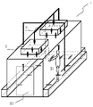
- FIG. 2 is a perspective view showing an example of a clean booth for sealing silicon polycrystal filling work according to the present invention.
- a clean booth for filling silicon polycrystal is disposed in a clean raw material preparation chamber.
- the sealed clean booth 1 has the side and ceiling surfaces completely sealed with the panel and the floor, and the entrance / exit 20 is provided on the side.
- the panel is kept highly airtight with a clean room high heat insulation panel and clean room sealant in order to increase air conditioning efficiency, and the entrance / exit 20 is provided with a resin belt drive and a dustproof cover on the movable part and is an automatic door considering dust generation prevention. It is desirable.
- an exhaust port 4 is provided on a side surface other than the side surface provided with the entrance / exit 20 within a height of 300 mm from the floor surface, and the air 10 exhausted by the fan filter device 3 (FFU) connected by the circulation line 14 is circulated.
- FFU fan filter device
- clean air 11 is supplied into the clean booth to form a downflow (laminar flow). Further, in order to suppress the deterioration of the working environment due to the internal lighting of the closed clean booth 1 and the heat generated by the worker 21, a part of the exhausted air 10 is branched to the air conditioning line 15, and the clean room air conditioner 2 It is also possible to supply air to the fan / filter device 3 in harmony with air. Further, the outside air 13 (clean air in the raw material preparation chamber) that is fresh air is taken in for the worker, and the inside of the closed clean booth 1 is not pressurized too much from the raw material preparation chamber outside the booth. Clean exhaust air 12 is discharged.
- the outside air 13 and the clean exhaust air 12 are adjusted by the differential pressure sensor 7 for detecting the pressure difference between the inside of the clean booth 1 and the outside of the clean booth 1 to adjust the opening degree of the intake damper 8 and the blower damper 9, When 20 is closed, the pressure is controlled at about ⁇ 2 to +2 Pa.
- the clean exhaust air 12 directly discharges the clean air that has passed through the fan / filter device 3 from a predetermined height that is not affected by dust generation. There is no contamination.
- the entrance / exit 20 is used when the quartz crucible 17, the silicon polycrystal 18, and other filling jigs are carried into the sealed clean booth 1 in order to fill the quartz crucible 17 with the silicon polycrystal 18, or quartz Opened when carrying out the filling of the silicon polycrystal 18 into the crucible 17.
- the clean booth 1 of the present invention has a control mechanism 25 for controlling the pressure inside the clean booth when the entrance 20 of the clean booth 1 is opened.
- the opening / closing port 20 is transmitted to the control unit 19 by the door switch / sensor 6.
- the control unit 19 immediately reduces the motor output of the fan filter device 3 to reduce the circulating air flow and at the same time adjusts the exhaust amount of the clean exhaust air 12 and the air supply amount of the outside air 13.
- the opening of the intake damper 8 to be adjusted is varied, and the differential pressure detected by the differential pressure sensor 7 is -2 to 0 Pa, that is, the inside of the closed clean booth 1 is the same pressure as the raw material preparation chamber or the raw material preparation Reduce the pressure slightly from the room.
- the control unit 19 opens the entrance / exit 20 to enable the quartz crucible 17 and the silicon polycrystal 18 to be carried in / out.
- the differential pressure between the sealed clean booth 1 and the raw material preparation chamber to ⁇ 2 to 0 Pa, for example, in the sealed clean booth 1, the opening of the plastic bag and the silicon polycrystal 18 are performed.
- the sealed clean booth 1 of the present invention by providing the static eliminator 16, it is difficult for the dust to be adsorbed to the panel, and the side surface other than the side surface provided with the entrance / exit 20 is exhausted within a height of 300 mm from the floor surface. Dust can be efficiently removed by forming the down flow (laminar flow) by providing the opening 4, circulating the air 10 exhausted by the fan filter device 3, and supplying clean air 11.
- a removable primary filter 5 at the exhaust port 4
- the life of the filter of the fan / filter device 3 can be extended.
- an ionizer can be installed in the static eliminator 16, but the generation of static electricity can be suppressed by humidifying the circulating air with clean water (pure water) to a relative humidity of 40 to 65%.
- the clean booth for filling silicon polycrystal according to the present invention is generated from the silicon polycrystal 18 'as in the conventional open booth for filling silicon polycrystal shown in FIG.
- the discharged dust is not discharged from the open clean booth 1 ′ as air 23 to be discharged outside the apparatus, so other apparatuses and jigs installed in the raw material preparation chamber, or stored silicon polycrystal It is possible to suppress contamination of the quartz crucible before filling and the quartz crucible that has been filled with silicon polycrystal.
- the quartz crucible is filled in the quartz crucible in the sealed clean booth of the present invention as shown in FIG.
- the amount of contamination in a raw material preparation room was measured.
- the clean booth was equipped with an ionizer as a static eliminator and a primary filter at the exhaust port.
- the differential pressure between the sealed clean booth of the present invention and the raw material preparation chamber was controlled so that the differential pressure when the inlet / outlet 20 was closed was 1 Pa, and the differential pressure when the inlet / outlet was opened was ⁇ 1 Pa.
- the quartz crucible used in the filling operation had a diameter of 800 mm and a polycrystalline filling amount of 400 kg.
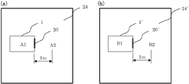
- the measurement was carried out by installing an air particle counter conforming to ISO 21501-4 (JIS B 9921) at the center of the clean booth at a measurement point A1 in the clean booth having a floor height of 1 m. Further, in the raw material preparation room outside the clean booth, the measurement was performed by installing it at a measurement point A2 outside the clean booth 1 m from the entrance 20 of the clean booth and 1 m from the floor.
- Measurements were continuously made both in the clean booth and in the raw material preparation room outside the clean booth, and the maximum values of the number of particles (particle size of 0.3 ⁇ m or more) in 1 m 3 were compared as cleanliness. The measurement was performed under normal conditions when the filling operation was not performed, during the filling operation, and when the clean booth door was opened.
- Comparative Example 1 A conventional clean booth 1 ′ as shown in FIG. 3 is used, and is placed in the raw material preparation chamber 24 ′ as shown in FIG. 4B.
- the air particle counter is located in the center of the clean booth, on the floor. Installed at a measurement point B1 in a clean booth with a surface height of 1 m, except at a raw material preparation room outside the clean booth at a measurement point B2 outside the clean booth at 1 m from the clean booth entrance 20 'and 1 m from the floor.
- work in an Example and a comparative example was performed independently.
- Table 1 shows the respective measurement points in Example and Comparative Example 1, and the maximum number of particles under each condition.
- Table 2 shows the upper limit concentration of the ISO cleanliness class (measured particle size 0.3 ⁇ m or more).
- the raw material preparation room is ISO cleanliness class 4.
- ISO cleanliness class 4 the prior art (Comparative Example 1), 100,000 or more dusts are generated in the clean booth 1 ′ that is open during the work (measurement point B1 in the clean booth during the work), and part of the raw material is prepared outside the apparatus. It was discharged into the room (measurement point B2 outside the clean booth during work). At this time, it was found that the raw material preparation chamber 24 'of Comparative Example 1 was contaminated to ISO cleanliness class 5-6.
- the number of particles in the raw material preparation chamber outside the apparatus does not change at all even during the work. Even when the door is opened after the work is completed, the number of particles outside the device (measurement point A2 outside the clean booth when the door is open) does not change at all, and the dust in the sealed clean booth 1 is not discharged outside the device. I was able to prove that. In the present invention, it was also confirmed that by installing an ionizer as a static eliminator and a primary filter at the exhaust port, the dust is not adsorbed to the panel and can be efficiently collected by downflow (during operation). Difference between measurement point A1 in the clean booth and measurement point B1 in the clean booth).
- Comparative Example 2 Furthermore, it is a sealed clean booth similar to the present invention, but the same conditions (quartz crucible aperture, silicon polycrystal filling amount, measurement conditions) even in a sealed clean booth that does not control the chamber pressure in the clean booth when opening and closing the entrance / exit
- the cleanliness of the raw material preparation room inside and outside the clean booth was measured.
- the air particle counter was installed in the same manner as in the example, and the measurement point inside the clean booth was C1, and the measurement point outside the clean booth was C2.
- Table 3 shows each measurement point in Comparative Example 2 and the maximum number of particles under each condition.
- the maximum number of particles in the clean booth during the operation of the clean booth measuring point A1 and the clean booth measuring point C1 is almost the same, and as in the previous embodiment, an ionizer is used as the static eliminator and the primary at the exhaust port.
- an ionizer is used as the static eliminator and the primary at the exhaust port.
- the present invention is not limited to the above embodiment.
- the above-described embodiment is an exemplification, and the present invention has any configuration that has substantially the same configuration as the technical idea described in the claims of the present invention and that exhibits the same effects. Are included in the technical scope.
Landscapes
- Engineering & Computer Science (AREA)
- Chemical & Material Sciences (AREA)
- Architecture (AREA)
- Materials Engineering (AREA)
- Metallurgy (AREA)
- Organic Chemistry (AREA)
- Crystallography & Structural Chemistry (AREA)
- Combustion & Propulsion (AREA)
- Mechanical Engineering (AREA)
- General Engineering & Computer Science (AREA)
- Civil Engineering (AREA)
- Structural Engineering (AREA)
- Crystals, And After-Treatments Of Crystals (AREA)
- Silicon Compounds (AREA)
Abstract
La présente invention concerne une cabine propre pour charger du silicium polycristallin dans un creuset en quartz, la cabine propre étant scellée par une surface de plafond, une surface latérale et une surface inférieure, et comporte : une entrée disposée sur la surface latérale ; un ventilateur et un dispositif de filtre disposés sur la surface de plafond ; un trou d'échappement disposé sur une partie inférieure de la surface latérale ; et un mécanisme de commande. Le mécanisme de commande souffle l'air nettoyé par le ventilateur et le dispositif de filtre dans la cabine propre, fait circuler l'air à l'intérieur de la cabine propre en évacuant l'air de l'intérieur de la cabine propre à travers le trou d'échappement et en renvoyant l'air au ventilateur et au dispositif de filtre, et commande la pression à l'intérieur de la cabine propre lorsque l'entrée est ouverte de façon à être égale ou inférieure à la pression à l'extérieur de la cabine propre. En conséquence, l'invention concerne une cabine propre dans laquelle la poussière générée pendant une étape de chargement de silicium polycristallin dans un récipient de matière première lors de la fabrication de silicium monocristallin ne contamine pas l'environnement ambiant.
Priority Applications (2)
| Application Number | Priority Date | Filing Date | Title |
|---|---|---|---|
| KR1020207022614A KR102611746B1 (ko) | 2018-03-15 | 2019-02-13 | 실리콘다결정 충전작업용의 클린부스 |
| CN201980012995.4A CN111712673A (zh) | 2018-03-15 | 2019-02-13 | 多晶硅填充作业用的清洁室 |
Applications Claiming Priority (2)
| Application Number | Priority Date | Filing Date | Title |
|---|---|---|---|
| JP2018-048176 | 2018-03-15 | ||
| JP2018048176A JP6911799B2 (ja) | 2018-03-15 | 2018-03-15 | シリコン多結晶充填作業用のクリーンブース |
Publications (1)
| Publication Number | Publication Date |
|---|---|
| WO2019176424A1 true WO2019176424A1 (fr) | 2019-09-19 |
Family
ID=67908302
Family Applications (1)
| Application Number | Title | Priority Date | Filing Date |
|---|---|---|---|
| PCT/JP2019/005083 Ceased WO2019176424A1 (fr) | 2018-03-15 | 2019-02-13 | Cabine propre pour charger du silicium polycristallin |
Country Status (4)
| Country | Link |
|---|---|
| JP (1) | JP6911799B2 (fr) |
| KR (1) | KR102611746B1 (fr) |
| CN (1) | CN111712673A (fr) |
| WO (1) | WO2019176424A1 (fr) |
Cited By (1)
| Publication number | Priority date | Publication date | Assignee | Title |
|---|---|---|---|---|
| JP7504328B1 (ja) * | 2022-12-19 | 2024-06-21 | 株式会社トクヤマ | 多結晶シリコン塊用品質検査室構造 |
Families Citing this family (1)
| Publication number | Priority date | Publication date | Assignee | Title |
|---|---|---|---|---|
| CN112781142A (zh) * | 2020-12-24 | 2021-05-11 | 珠海格力电器股份有限公司 | 实验室空气调节系统及其控制方法 |
Citations (5)
| Publication number | Priority date | Publication date | Assignee | Title |
|---|---|---|---|---|
| JPH02109941U (fr) * | 1989-02-17 | 1990-09-03 | ||
| US5641354A (en) * | 1995-07-10 | 1997-06-24 | Seh America, Inc. | Puller cell |
| JPH1096332A (ja) * | 1996-09-20 | 1998-04-14 | Mitsubishi Electric Corp | クリーンルーム |
| JP2002138620A (ja) * | 2000-10-31 | 2002-05-17 | Shin Etsu Handotai Co Ltd | 引上げ室 |
| JP2015052430A (ja) * | 2013-09-09 | 2015-03-19 | 新日本空調株式会社 | クリーンルーム内に設置された高清浄度低露点設備における製造部品の搬入方法 |
Family Cites Families (7)
| Publication number | Priority date | Publication date | Assignee | Title |
|---|---|---|---|---|
| JP3158328B2 (ja) | 1993-12-20 | 2001-04-23 | 三菱マテリアル株式会社 | 単結晶引上装置用原料組み込み方法及び装置 |
| JPH10132346A (ja) * | 1996-10-25 | 1998-05-22 | Aoki Corp | クリーンルーム・システム及びその管理方法 |
| CN201281412Y (zh) * | 2008-10-09 | 2009-07-29 | 苏州克林络姆空调系统工程有限公司 | 一种层流洁净室 |
| CN201279461Y (zh) * | 2008-10-09 | 2009-07-29 | 苏州克林络姆空调系统工程有限公司 | 一种洁净室 |
| CN102644970A (zh) * | 2012-05-18 | 2012-08-22 | 苏州市时代工程咨询设计管理有限公司 | 独立空调净化系统 |
| CN106225071B (zh) * | 2016-08-26 | 2022-01-14 | 无锡中微掩模电子有限公司 | 一种双循环温湿度控制系统 |
| JP6453284B2 (ja) * | 2016-09-02 | 2019-01-16 | 伸和コントロールズ株式会社 | 空気調和システム |
-
2018
- 2018-03-15 JP JP2018048176A patent/JP6911799B2/ja active Active
-
2019
- 2019-02-13 WO PCT/JP2019/005083 patent/WO2019176424A1/fr not_active Ceased
- 2019-02-13 KR KR1020207022614A patent/KR102611746B1/ko active Active
- 2019-02-13 CN CN201980012995.4A patent/CN111712673A/zh active Pending
Patent Citations (5)
| Publication number | Priority date | Publication date | Assignee | Title |
|---|---|---|---|---|
| JPH02109941U (fr) * | 1989-02-17 | 1990-09-03 | ||
| US5641354A (en) * | 1995-07-10 | 1997-06-24 | Seh America, Inc. | Puller cell |
| JPH1096332A (ja) * | 1996-09-20 | 1998-04-14 | Mitsubishi Electric Corp | クリーンルーム |
| JP2002138620A (ja) * | 2000-10-31 | 2002-05-17 | Shin Etsu Handotai Co Ltd | 引上げ室 |
| JP2015052430A (ja) * | 2013-09-09 | 2015-03-19 | 新日本空調株式会社 | クリーンルーム内に設置された高清浄度低露点設備における製造部品の搬入方法 |
Cited By (1)
| Publication number | Priority date | Publication date | Assignee | Title |
|---|---|---|---|---|
| JP7504328B1 (ja) * | 2022-12-19 | 2024-06-21 | 株式会社トクヤマ | 多結晶シリコン塊用品質検査室構造 |
Also Published As
| Publication number | Publication date |
|---|---|
| KR102611746B1 (ko) | 2023-12-11 |
| JP2019156694A (ja) | 2019-09-19 |
| CN111712673A (zh) | 2020-09-25 |
| KR20200133724A (ko) | 2020-11-30 |
| JP6911799B2 (ja) | 2021-07-28 |
Similar Documents
| Publication | Publication Date | Title |
|---|---|---|
| CN107039322B (zh) | 微环境装置 | |
| CN102280363B (zh) | 基板处理设备 | |
| US10825697B2 (en) | Substrate processing apparatus, method of manufacturing semiconductor device, and recording medium | |
| US7828928B2 (en) | Vacuum processing apparatus | |
| TWI500104B (zh) | Atmosphere replacement device | |
| JPH08510826A (ja) | 環境制御システム | |
| KR20180059914A (ko) | 반도체 시스템의 습도 제어 | |
| WO2019176424A1 (fr) | Cabine propre pour charger du silicium polycristallin | |
| KR102452122B1 (ko) | 기판 처리 장치, 반도체 장치의 제조 방법 및 프로그램 | |
| US11515177B2 (en) | Circulating EFEM | |
| CN116525486A (zh) | 晶圆除胶机 | |
| JP6885132B2 (ja) | Efem及びefemのガス置換方法 | |
| JP5755845B2 (ja) | 処理装置 | |
| JP2003264219A (ja) | 局所クリーン装置 | |
| JP6973340B2 (ja) | 給排気制御装置、ウェーハ処理装置、及びウェーハ処理方法 | |
| CN103765557A (zh) | 气相沉积设备 | |
| WO1999028965A1 (fr) | Recipient et chargeur de substrat | |
| JP7513399B2 (ja) | クリーンベンチ装置 | |
| JPH0364477A (ja) | 常圧処理装置 | |
| JP4928368B2 (ja) | 基板処理装置及び半導体装置の製造方法 | |
| JP7031131B2 (ja) | Efem及びefemのガス置換方法 | |
| CN217821262U (zh) | 一种硒鼓生产用刮刀涂粉装置 | |
| CN220048578U (zh) | 一种用于石墨坩埚的静电喷涂装置 | |
| CN219873418U (zh) | 一种用于晶圆上下料的防尘装置及其晶圆除胶设备 | |
| CN219541166U (zh) | 一种超声波槽体及电子级电极板和瓷环清洗设备 |
Legal Events
| Date | Code | Title | Description |
|---|---|---|---|
| 121 | Ep: the epo has been informed by wipo that ep was designated in this application |
Ref document number: 19768575 Country of ref document: EP Kind code of ref document: A1 |
|
| NENP | Non-entry into the national phase |
Ref country code: DE |
|
| 122 | Ep: pct application non-entry in european phase |
Ref document number: 19768575 Country of ref document: EP Kind code of ref document: A1 |