WO2020196417A1 - Dispositif de chauffage à film - Google Patents
Dispositif de chauffage à film Download PDFInfo
- Publication number
- WO2020196417A1 WO2020196417A1 PCT/JP2020/012748 JP2020012748W WO2020196417A1 WO 2020196417 A1 WO2020196417 A1 WO 2020196417A1 JP 2020012748 W JP2020012748 W JP 2020012748W WO 2020196417 A1 WO2020196417 A1 WO 2020196417A1
- Authority
- WO
- WIPO (PCT)
- Prior art keywords
- conductive
- pattern
- connection terminal
- film heater
- conductive wire
- Prior art date
- Legal status (The legal status is an assumption and is not a legal conclusion. Google has not performed a legal analysis and makes no representation as to the accuracy of the status listed.)
- Ceased
Links
Images


Classifications
-
- H—ELECTRICITY
- H05—ELECTRIC TECHNIQUES NOT OTHERWISE PROVIDED FOR
- H05B—ELECTRIC HEATING; ELECTRIC LIGHT SOURCES NOT OTHERWISE PROVIDED FOR; CIRCUIT ARRANGEMENTS FOR ELECTRIC LIGHT SOURCES, IN GENERAL
- H05B3/00—Ohmic-resistance heating
- H05B3/02—Details
-
- H—ELECTRICITY
- H05—ELECTRIC TECHNIQUES NOT OTHERWISE PROVIDED FOR
- H05B—ELECTRIC HEATING; ELECTRIC LIGHT SOURCES NOT OTHERWISE PROVIDED FOR; CIRCUIT ARRANGEMENTS FOR ELECTRIC LIGHT SOURCES, IN GENERAL
- H05B3/00—Ohmic-resistance heating
- H05B3/10—Heating elements characterised by the composition or nature of the materials or by the arrangement of the conductor
- H05B3/12—Heating elements characterised by the composition or nature of the materials or by the arrangement of the conductor characterised by the composition or nature of the conductive material
-
- H—ELECTRICITY
- H05—ELECTRIC TECHNIQUES NOT OTHERWISE PROVIDED FOR
- H05B—ELECTRIC HEATING; ELECTRIC LIGHT SOURCES NOT OTHERWISE PROVIDED FOR; CIRCUIT ARRANGEMENTS FOR ELECTRIC LIGHT SOURCES, IN GENERAL
- H05B3/00—Ohmic-resistance heating
- H05B3/20—Heating elements having extended surface area substantially in a two-dimensional [2D] plane, e.g. plate-heater
Definitions
- the present invention relates to a film heater, and more particularly to a film heater provided on a film with a conductive pattern that can be electrically connected to an external power source.
- a film-like planar heating element having a conductive pattern for heating which is used by being attached to an adherend to be heated for the purpose of preventing ice / snow adhesion, snow melting, fogging, and heat retention. It has been known.
- Patent Document 1 discloses a planar heating element in which a bare nichrome wire processed into an arbitrary shape is arranged inside two multilayer composite films via an adhesive layer made of an insulating material. , It is described that this planar heating element is attached to a heating object by a double-sided adhesive tape, a double-sided adhesive film, or the like.
- Patent Document 2 describes a semi-cured sheet for manufacturing a hard planar heating element, which comprises a flexible planar heating element and a semi-cured semi-cured resin coating layer formed so as to include the heat-generating portion. Is disclosed.
- the semi-cured resin coating layer containing the heat generating portion is in a semi-cured state (B stage), has flexibility and plasticity, and has an adhesive surface, so that it can be applied to any shape of the adherend. It is described that it can be followed and pasted.
- Patent Document 3 a metal wire resistor formed in a predetermined pattern is provided on the surface or inside of a circular sheet-shaped flexible transparent base material having a fan-shaped notch having a central angle of 90 degrees or less.
- a planar heater for a traffic light is disclosed, wherein the straight portions of the fan-shaped notches are brought into contact with or close to each other to deform the flexible transparent substrate from a circular sheet to a conical sheet. It is described that even if the display window of the signal light has a dome shape, it is easy to make close contact with it.
- Patent Document 1 a bare nichrome wire is disposed inside between two multilayer composite films using an adhesive layer for fixing wiring, and a peripheral portion of the multilayer composite film is heat-sealed. ,
- the configuration is complicated.
- the invention disclosed in Patent Document 2 requires the use of a special resin film, requires special equipment such as completely curing the semi-cured resin coating layer by a photocuring method, and tends to complicate the construction method.
- the invention disclosed in Patent Document 3 is effective when the display window of the signal light has a dome shape, but it is difficult to use it in other cases.
- Patent Document 1 the bare nichrome wire is arranged on the adhesive layer for fixing the wiring, but the adhesive layer is liable to adhere dust in the manufacturing process, and the molded bare nichrome wire is formed. There is a problem that the shape of the is easily collapsed.
- Patent Document 2 uses a specific woven fabric woven by crossing a weft yarn made of a conductive yarn for heat generation and a warp yarn made of an insulating yarn at predetermined intervals as a heat generating portion, and Patent Document 3 uses a flexible woven fabric.
- a meandering groove is carved on the surface of the transparent transparent base material and a heating wire resistor is embedded along the groove to form a heat generating portion, the configuration and manufacturing process become complicated.
- the present inventors are super as a film heater that is easier to manufacture and can be easily attached to an adherend having an uneven shape without impairing the design of the adherend. It was examined to embed the conductive wire on the surface of the support sheet by utilizing the principle of ultrasonic fusion. In ultrasonic fusion, the surface of the support sheet made of a thermoplastic resin is melted while the conductive wire is fed out, and the conductive wire can be embedded in the surface of the support sheet.
- the material of the support sheet is a durable and hard material, or if a thin conductive wire is used in consideration of design, the conductive wire becomes thin due to the tension at the time of arrangement, and as a result, the conductive wire becomes thin. There was a problem that the resistance value increased. Further, even when the conductive wire was thick, an increase in the resistance value, which was considered to be caused by an increase in the shear stress between the conductive wire and the support sheet, was observed. Furthermore, it was also found that the problem of increasing the resistance value of the conductive wire was remarkable when the conductive wire was coated.
- a bonding layer that is solid at room temperature and exhibits adhesiveness by heating and melting is provided on one surface of a support sheet made of a transparent thermoplastic resin sheet, and a conductive pattern made of conductive wires is provided on the bonding layer.
- the conductive pattern is a continuous line consisting of a connection terminal portion, a lead portion extending from the connection terminal portion, and an overall non-linear heater portion continuing from the lead portion. It is a film heater characterized by being provided as a shape pattern.
- the present invention is a film heater in which the conductive pattern has a certain diameter and a circular conductive wire is embedded in a predetermined pattern on the surface of the bonding layer by ultrasonic fusion. Is.
- the surface rubber hardness of the bonding layer based on JIS K6301: 1995 is preferably 50 ° or less.
- the bonding layer may be made of a hot melt adhesive.
- the support sheet may be made of a polycarbonate resin.
- the conductive wires constituting the conductive pattern are covered with a self-bonding insulating film.
- the diameter of the conductive wire constituting the conductive pattern is preferably 150 ⁇ m or less.
- the conductive pattern has two connection terminal portions in which the conductive wire is bent at a plurality of locations, and at least two lead portions extending from one of the two connection terminal portions, and the two conductor portions.
- connection terminal portion can be formed in a lattice shape in which a linear pattern in which conductive wires are bent at a plurality of points intersect vertically and horizontally.
- an exterior sheet made of another transparent thermoplastic resin sheet that covers the conductive pattern is provided on the surface of the support sheet provided with the conductive pattern, and the exterior sheet is provided with the connection terminal portion. It can be a film heater provided with a through hole that exposes at least a part of the above.
- a metal plate can be further provided on the connection terminal portion.
- the conductive wires constituting the conductive pattern are covered with a self-bonding insulating film.
- the adhesive layer may be provided on the surface of the support sheet opposite to the surface on which the conductive pattern is provided.
- the film heater of the present invention is a transparent film heater as a whole, and can be attached to various adherends without impairing the design of the adherend to be heated.
- a bonding layer having a low surface rubber hardness on the surface of the support sheet, it is possible to suppress an increase in the resistance value of the conductive wire even if the material of the support sheet is a durable and hard material.
- the bonding layer can be heat-bonded, and when the adherend is a resin molded body, in-mold transfer capable of forming a film heater on the surface of the resin molded body at the same time as resin molding is possible.
- the conductive pattern can be continuously formed by a single conductive wire, which facilitates manufacturing.
- the present invention is a film heater having good moldability, high mechanical strength, and excellent adhesiveness to an adherend, and can be applied to various applications such as prevention of ice and snow adhesion, snow melting, fogging prevention, and heat retention.
- (A) is a plan view schematically showing an example of the film heater of the present invention, and (b) is a sectional view thereof.
- (A) is a plan view schematically showing another example of the film heater of the present invention, and (b) is a sectional view thereof.
- It is a schematic diagram which shows another example of the conductive pattern of this invention.
- (A) is a plan view schematically showing an example of the film heater of the present invention using an exterior sheet, and (b) is a sectional view thereof.
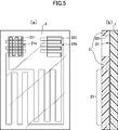
- (A) is a plan view schematically showing an example using the exterior sheet of the present invention, and (b) is a sectional view thereof.
- FIG. 1A is a plan view schematically showing an example of the film heater of the present invention.
- FIG. 1B is a cross-sectional view schematically showing an example of the film heater of the present invention.
- a bonding layer 2 which is solid at room temperature and exhibits adhesiveness by heating and melting is provided on one surface of a support sheet 1 made of a transparent thermoplastic resin sheet, and a conductive wire made of a conductive wire is provided on the bonding layer.
- Pattern 3 is provided.
- connection terminal portion 31, the lead portion 32 extending from the connection terminal portion 31, and the overall non-linear heater portion 33 continuing from the lead portion 32 are continuous with one conductive wire. It is provided as a linear pattern.
- end portion of the lead portion 32 extending linearly is referred to as a continuous terminal portion 31.
- the support sheet is made of a transparent thermoplastic resin sheet in order to produce a transparent film heater as a whole. If the film heater is transparent as a whole, it can be attached to various adherends without impairing the design of the adherend to be heated. Further, by using a thermoplastic resin sheet, it can be easily attached to an adherend having an uneven shape. In particular, when the adherend is a resin molded body, vacuum forming or heat pressing is performed.
- a film heater can be formed on the surface of a resin molded body by a molding method such as molding, laminating molding, in-mold molding, or insert molding.
- thermoplastic resin sheet ethylene-based resin, propylene-based resin, polyolefin-based resin, thermoplastic polyester-based resin, polyamide-based resin, polyvinyl chloride, polycarbonate, ABS resin and the like can also be used, and two or more of these are contained. It may be something to do. Especially for outdoor applications, it is preferable to use a polycarbonate resin having excellent mechanical strength and weather resistance. Inorganic fine powder or organic filler, dispersant, antioxidant, compatibilizer, ultraviolet stabilizer, antiblocking agent, antistatic agent and the like can be appropriately added to the thermoplastic resin sheet.
- the thickness of the thermoplastic resin sheet is preferably 0.030 mm to 1.000 mm, preferably 0.100 mm to 0.700 mm.
- the bonding layer is preferably a bonding layer that is solid at room temperature and exhibits adhesiveness by heating and melting. Since it is solid at room temperature and does not have tack, adhesion of dust and the like is suppressed, and handling at the time of sticking to the adherend is improved.
- a hot melt adhesive can be used.
- an adhesive composed of ethylene vinyl acetate, an olefin, synthetic rubber, polyamide, polyester or the like as a main component can be used.
- the thickness of the bonding layer is preferably 0.05 mm to 0.5 mm, preferably 0.1 mm to 0.3 mm.
- the bonding layer is used for embedding a conductive wire on the surface of a support sheet by utilizing the principle of attachment to an adherend or ultrasonic fusion.
- ultrasonic fusion the surface of the bonding layer is melted while feeding out the conductive wire, and the conductive wire can be embedded in the surface of the bonding layer.
- the material of the layer in which the conductive wire is embedded is a durable and hard material, or if a thin conductive wire is used in consideration of design, the resistance value of the conductive wire will increase due to the tension at the time of arrangement.
- the surface rubber hardness based on JIS K6301: 1995 is 50 ° or less.
- the bonding layer has a softening temperature higher than the operating temperature of the film heater of the present invention and melts at the temperature at which the conductive wire is embedded in the surface of the bonding layer.
- the conductive pattern can be formed by printing with a conductive ink such as silver paste or by etching a metal foil such as copper foil, but a circular conductive wire having a certain diameter in a cross-sectional view is formed as a predetermined pattern. It is preferable that the heater portion, the lead portion, and the connection terminal portion can be easily formed as one continuous linear shape.
- the conductive wires are configured to include at least a metal wire, preferably the metal wire is coated with a self-bonding insulating film.
- the metal wire is, for example, a metal wire such as copper, iron, gold, copper nickel, nickel chromium, iron nickel chromium, etc., but other materials may be used as long as they have conductivity. From the viewpoint of electrical resistance, durability, and cost, it is preferable to use copper or a copper alloy in which zinc, lead, tin, silver, aluminum, nickel, beryllium, zirconium, or the like is used alone or in combination with copper.
- the insulating film that coats the metal wire is an insulating resin film, and the conductive wire coated with the insulating film can be a commercially available enamel wire.
- Specific examples of the insulating resin film include polyester, polyethylene, polyurethane, polyvinyl chloride, polyamide, polyimide, polyesterimide, polyamideimide, and fluororesin.
- the insulating film is typically black, but may be colored in any color according to the color of the adherend to be heated.
- the diameter of the conductive wire constituting the conductive pattern is, for example, 0.03 mm to 0.2 mm.
- the film heater is transparent as a whole, and for that purpose, the conductive wire should be as thin as possible.
- the diameter of the conductive wire is preferably 0.05 mm to 0.15 mm.
- the length of the conductive wire depends on the pattern form of the conductive pattern and the like. To form a conductive pattern, it can typically be formed by drawing a conductive wire on the bonding layer and drawing a predetermined pattern form, and fixing by embedding the conductive wire at least on the surface of the bonding layer. can do.
- the conductive wire For embedding the conductive wire in the surface of the bonding layer, for example, it is desirable to embed the conductive wire in the surface of the support sheet by utilizing the principle of ultrasonic fusion.
- a wiring drawing device capable of melting the surface of the bonding layer while feeding out the conductive wire and embedding the conductive wire in the surface of the bonding layer can be used.
- the ultrasonic head provided in such a wiring drawing device, the conductive wire can be embedded in the surface of the joint layer by vibration and pressurization while feeding the conductive wire onto the surface of the joint layer.
- the conductive pattern By embedding the conductive wire in the surface of the joint layer, the conductive pattern can be positioned on the joint layer, and the displacement of the conductive wire due to an external impact or the like can be suppressed. Further, by embedding the conductive wire on the surface of the bonding layer, it is possible to reduce the degree of surface unevenness due to the arrangement of the conductive wire on the surface of the bonding layer.
- connection terminal portion 31 the connection terminal portion 31, the lead portion 32 extending from the connection terminal portion 31, and the overall non-linear heater portion 33 continuing from the lead portion 32 are one. It is provided as a continuous linear pattern composed of conductive wires.
- connection terminal portion 31 the end portion of the lead portion 32 drawn from one continuous conductive wire is used as the connection terminal portion 31.
- the connection terminal portion may be further provided with a conductive piece made of a metal plate on the connection terminal portion in order to improve the connection efficiency with the external electrode.
- the metal plate for example, copper, copper alloy, iron, iron and nickel alloy and the like can be used.
- the conductive wire is covered with an insulating film, the insulating film covering the conductive wire at the connection terminal portion is removed to expose the metal wire inside. As a method of exposing, cutting with a milling device or the like is possible, but the insulating film can be melted and removed by heat when soldering to a metal plate or an external electrode.
- the heater portion 33 is routed from the lead portion 32 extending from the connection terminal portion 31 and is formed as a non-linear linear pattern as a whole.
- the heater portion 33 has a relatively short length.
- the bent part and the straight part having a relatively long length are repeated, and the pattern is bent and meandered at a plurality of places.
- the pattern of the heater portion can be any pattern in consideration of the shape of the adherend, the heating area, and the heating efficiency, and may be a repeating curved shape that does not include a straight portion or a spiral shape. In FIG.
- the conductive pattern is composed of a pair of left and right connection terminal portions 31 and a pair of left and right lead portions 32 centered on the heater portion 33, and the lead portion 32a starts from the end of one connection terminal portion 31a by a conductive wire.
- the heater portion 33 is formed by the conductive wire drawn from the lead portion 32a, the other lead portion 32b is extended from the heater portion 33, and the other lead portion 32b is extended to the other connection terminal portion 31b.
- a continuous linear heater portion 33, a lead portion 32, and a connection terminal portion 31 are formed of the conductive wires of the above.
- an antifouling layer an antifogging layer, an antistatic layer, a hard coat layer and the like may be formed on the surface opposite to the bonding layer of the support sheet, if necessary.
- FIG. 2A is a plan view schematically showing an example of the film heater of the present invention.
- FIG. 2B is a cross-sectional view schematically showing an example of the film heater of the present invention.
- a conductive pattern 22 made of a conductive wire is provided on one surface of a support sheet 1 made of a transparent thermoplastic resin sheet.
- the conductive pattern is a non-linear shape as a whole connected to the connection terminal portions 21a and 21b (21 in FIG.
- the heater portions 231 and 232 are provided as a continuous linear pattern composed of a single conductive wire.
- a conductive pattern it can typically be formed by drawing a conductive wire around on the support sheet and drawing a predetermined pattern form, and fixing by embedding the conductive wire at least on the surface of the support sheet. can do.
- a wiring drawing device capable of melting the surface of a support sheet made of a thermoplastic resin while feeding out the conductive wire and embedding the conductive wire in the surface of the support sheet can be used.
- the conductive wire can be embedded in the surface of the support sheet by vibration and pressurization while feeding the conductive wire onto the surface of the support sheet.
- the conductive pattern can be positioned on the support sheet, and the displacement of the conductive wire due to an external impact or the like can be suppressed.
- the conductive wire on the surface of the support sheet it is possible to reduce the degree of surface unevenness due to the arrangement of the conductive wire on the surface of the support sheet.
- a bonding layer that is solid at room temperature and exhibits adhesiveness by heating and melting is provided on one surface of the support sheet 1, and the conductive wire is provided on the surface of the bonding layer.
- a conductive pattern composed of conductive wires may be provided on the bonding layer.
- the conductive pattern is an overall non-linear heater connected to the connection terminal portions 21a and 21b, the lead wires 221 and 222 extending from the connection terminal portions 21a and 21b, and the lead wires 221 and 222.
- the portions 231 and 232 are provided as a continuous linear pattern composed of one conductive wire.
- the conductive pattern includes at least two first lead wires 221 and second lead wire 222, and a first lead wire 221 extending from one connection terminal portion 21 in which the conductive wires are bent at a plurality of places. It has a connected first heater section 231 and a second heater section 232 connected to the second lead wire 222, and the first heater section 231 and the second heater section 232 are arranged in parallel. By arranging the first heater portion 231 and the second heater portion 232 in parallel, each of these heater portions is connected to the two connection terminal portions. The combined resistance of the conductive wires arranged in parallel is lower than the combined resistance of the conductive wires arranged in series between the two connection terminals using the conductive wires of the same length.
- connection terminal portion 21a is arranged in parallel as a continuous linear pattern composed of one conductive wire by forming a lattice shape in which the linear patterns in which the conductive wires are bent at a plurality of points intersect vertically and horizontally.
- the heater portions 231 and 232 are routed from the lead wire extending from the connection terminal portion 21 and formed as a non-linear linear pattern as a whole.
- the heater portions 231 and 232 are relatively long. A short bent part and a relatively long straight part are repeated, and the pattern is bent and meandered at a plurality of places.
- the pattern of the heater portion can be any pattern in consideration of the shape of the adherend, the heating area, and the heating efficiency, and may be a repeating curved shape that does not include a straight portion or a spiral shape. In FIG.
- the conductive pattern is composed of a pair of left and right connection terminal portions 21a and 21b and a pair of left and right lead portions 221a and 222a, 221b and 222b, and becomes one connection terminal portion 21a by a conductive wire.
- a folded shape pattern is formed, one of the first lead wires 221a is extended from the folded shape pattern, and the first heater portion 231 is formed by the conductive wire drawn from the first lead wire 221a, and the first heater portion 231 is formed.
- the other first lead wire 221b is extended from the heater portion 231 to form the other folded-shaped connection terminal portion 21b, and the other second lead wire 222b is extended from the other connection terminal portion 21b.
- the second heater portion 232 is formed by the conductive wire drawn from the other second lead wire 222b, and one second lead wire 222a is extended from the second heater portion 232 to connect with the one connection terminal portion 21a.
- a folded shape pattern is formed that is bent in a direction that intersects with the folded shape pattern, and one connection terminal portion 21a is formed in a lattice shape in which a linear pattern in which conductive wires are bent at a plurality of points intersect vertically and horizontally. There is.
- FIG. 3 shows an example in which both the pair of left and right connection terminal portions 21a and 21b are formed in a lattice shape in which a linear pattern in which conductive wires are bent at a plurality of locations intersect vertically and horizontally.
- an exterior sheet made of another transparent thermoplastic resin sheet that covers the conductive pattern is provided on the surface of the support sheet provided with the conductive pattern, and the exterior sheet is provided with a connection terminal portion. It can be a film heater provided with a through hole that exposes at least a part of the above.
- FIG. 4A is a plan view schematically showing an example of the exterior sheet of the present invention.
- FIG. 4B is a cross-sectional view schematically showing an example of the exterior sheet of the present invention.
- the exterior sheet 3 having substantially the same dimensions as the support sheet is provided with through holes 331a and 331b for exposing at least a part of the connection terminal portion to the outside.
- thermoplastic resin sheet similar to the support sheet can be used, and the surface of the support sheet on which the conductive pattern is formed can be bonded by heat treatment and / or press treatment. If necessary, an adhesive layer, an adhesive layer, a heat seal layer, or the like may be interposed between the support sheet and the exterior sheet for bonding.
- the exterior sheet may be provided with a through hole that exposes at least a part of the connection terminal portion to the outside.
- a cutting means such as punching with a die or a laser device can be used to form a through hole in the exterior sheet for exposing the contact terminal portion. Specifically, a biku blade, a cutting blade, a laser cutter, or A milling device or the like can be used.
- FIG. 5A is a plan view schematically showing an example using the exterior sheet of the present invention.
- FIG. 5B is a cross-sectional view schematically showing an example using the exterior sheet of the present invention.
- the entire surface of the support sheet 1 on which the conductive pattern is formed is covered with the exterior sheet 3 except for the through hole 331, whereby the overall transparent thermoplastic resin sheet is used.
- the connection terminal portion 21 can be reliably electrically connected to an external power source. Further, it becomes possible to protect the heater portion and the lead portion on the surface of the support sheet by covering them with the exterior sheet.
- an antifouling layer, an antifogging layer, an antistatic layer, a hard coat layer, or the like may be formed on the surface of the exterior sheet.
- the adhesive layer may be provided on the surface of the support sheet opposite to the surface on which the conductive pattern is provided. By using the adhesive layer, it can be easily attached to an adherend having an uneven shape.
- the adhesive layer for example, an acrylic-based, urethane-based, epoxy-based, rubber-based, polyester-based, cellulose-based, or emulsion-based adhesive can be used. Further, if necessary, fillers, tackifiers, hardeners and the like can be appropriately used as additives for improving the characteristics of the pressure-sensitive adhesive.
- the thickness of the adhesive layer is not particularly limited as long as the adhesive strength can be obtained, and is usually 20 ⁇ m to 200 ⁇ m, preferably about 25 ⁇ m to 75 ⁇ m.
- the adhesive can be formed by using a coating method such as gravure coating, gravure reverse coating, comma coating, knife coating, and die coating.
- Example 1 A thermoplastic resin sheet (polycarbonate sheet DPI-AO manufactured by Mitsubishi Plastics, thickness 0.075 mm) to be a support sheet was prepared, and a bonding layer was formed on the surface of the support sheet.
- a polyester hot melt Toagosei Aron Melt PES-111EHW, thickness 0.1 mm was used.
- the surface rubber hardness of the joint layer was measured from a spring type A type based on JIS K6301: 1995 using HARDNESSTESTER ATYPE manufactured by Furusato Seiki Seisakusho. The measured surface rubber hardness was 50 °.
- a conductive wire (ELEKTRISOLA self-bonding coating lead wire AB15 ⁇ 0.1 mm) was applied to the surface of the bonding layer, and a wiring drawing device (Ruhramat WCE150, setting condition: USP1200, speed40%) equipped with an ultrasonic head was used. It was embedded to form a conductive pattern as shown in FIG.
- the conductive pattern has a lead portion length of 130 mm, a heater portion of 90 mm in a straight portion, a folded portion (pitch) of 10 mm, a number of folds (the number of lines in the straight portion) of 8 times, and a connection terminal portion of 17 mm in a straight portion. ..
- the film was cut into a length of 170 mm and a width of 120 mm to prepare a film heater.
- the resistance value before and after embedding was measured and the resistance increase rate was calculated.
- the resistance value was measured using an IWATSU multimeter.
- the resistance increase rate of the produced film heater was 2.0%.
- Example 2 A film heater was produced in the same manner as in Example 1 except that a bonding layer having a surface rubber hardness of 43 ° was used. The resistance increase rate of the produced film heater was 0.1%.
- Example 1 A film heater was produced in the same manner as in Example 1 except that a conductive pattern was directly formed on the surface of the support sheet without forming a bonding layer.
- the resistance increase rate of the produced film heater was 15.9%.
- Example 3 A thermoplastic resin sheet (polycarbonate sheet DPI-AO manufactured by Mitsubishi Resin Co., Ltd., thickness 0.075 mm) to be a support sheet is prepared, and a conductive wire (self-bonding film conducting wire AB15 ⁇ 0.10 mm manufactured by ELEKTRISOLA) is placed on the surface of the support sheet. It was embedded using a wiring drawing device equipped with an ultrasonic head (WCE150 manufactured by Ruhlamat, setting conditions: USP1200, speed 40%) to form a conductive pattern as shown in FIG. Regarding the conductive pattern, the lengths of the first heater portion and the second heater portion were set to 525 mm and 735 mm, respectively.
- WCE150 ultrasonic head
- the length of the heater portion is the length of the portion where the straight portion is repeated at a constant pitch (the bracket portion in FIG. 2).
- the first connection terminal portion has a straight line portion of 17 mm, a folded portion (pitch) of 0.3 mm, and the number of turns is a grid shape obtained by intersecting the folded shapes of 6 times, and the second connection terminal portion has a straight portion of 17 mm and a folded portion (folded portion).
- the pitch was 0.3 mm, and the number of turns was 6 times.
- a film heater was produced by punching a die into a length of 170 mm and a width of 120 mm.
- Example 4 A thermoplastic resin sheet (polycarbonate sheet DPI-AO thickness 0.075 mm manufactured by Mitsubishi Resin Co., Ltd.) to be an exterior sheet is attached to the surface of the support sheet to which the conductive pattern of Example 3 is wired, and a vacuum laminating machine (180 ° C.) is attached. After heat-pressing with 60 N / cm 2 ) and sufficiently adhering it on the support sheet, a milling device is used on the exterior sheet to expose the connection terminal part, and a through hole of 10 mm ⁇ 10 mm is formed at the position of the connection terminal part. Formed. At this time, the insulating film covering the conductive wire of the connection terminal exposed in the through hole was removed to expose the metal wire inside. Finally, a film heater was produced by punching a die into a length of 170 mm and a width of 120 mm.
Landscapes
- Surface Heating Bodies (AREA)
Abstract
L'invention concerne un dispositif de chauffage à film qui est transparent dans son ensemble, et qui peut être lié à diverses parties adhérées sans compromettre la conception de la partie adhérée, qui doit être chauffée. Ce dispositif de chauffage à film est caractérisé en ce que : une couche de jonction qui est solide à température ambiante et qui présente une adhérence lorsqu'elle est fondue par chauffage est disposée sur une surface d'une feuille de support comprenant une feuille de résine thermoplastique transparente ; un motif électroconducteur comprenant des fils électriquement conducteurs est disposé sur la couche de jonction ; et dans le motif électroconducteur, des parties de borne de connexion, des parties de fil s'étendant à partir des parties de borne de connexion, et une partie de chauffage qui est continue avec les parties de fil et qui est non linéaire dans son ensemble, sont fournies sous la forme d'un motif de type fil continu comprenant un fil électroconducteur.
Applications Claiming Priority (4)
| Application Number | Priority Date | Filing Date | Title |
|---|---|---|---|
| JP2019-063085 | 2019-03-28 | ||
| JP2019-063084 | 2019-03-28 | ||
| JP2019063085A JP7332317B2 (ja) | 2019-03-28 | 2019-03-28 | フィルムヒータ |
| JP2019063084A JP7249187B2 (ja) | 2019-03-28 | 2019-03-28 | フィルムヒータ |
Publications (1)
| Publication Number | Publication Date |
|---|---|
| WO2020196417A1 true WO2020196417A1 (fr) | 2020-10-01 |
Family
ID=72609819
Family Applications (1)
| Application Number | Title | Priority Date | Filing Date |
|---|---|---|---|
| PCT/JP2020/012748 Ceased WO2020196417A1 (fr) | 2019-03-28 | 2020-03-23 | Dispositif de chauffage à film |
Country Status (1)
| Country | Link |
|---|---|
| WO (1) | WO2020196417A1 (fr) |
Cited By (1)
| Publication number | Priority date | Publication date | Assignee | Title |
|---|---|---|---|---|
| WO2025033517A1 (fr) * | 2023-08-09 | 2025-02-13 | Nissha株式会社 | Feuille électroconductrice et son procédé de fabrication, et article moulé électroconducteur et son procédé de fabrication |
Citations (7)
| Publication number | Priority date | Publication date | Assignee | Title |
|---|---|---|---|---|
| JPS59146182A (ja) * | 1984-01-13 | 1984-08-21 | 松下電器産業株式会社 | 面状発熱体装置 |
| JPS6090790U (ja) * | 1983-11-28 | 1985-06-21 | 昭和電線電纜株式会社 | ヒ−テイングユニツト |
| JP2003257597A (ja) * | 2002-02-28 | 2003-09-12 | Yukio Shiroo | 面状発熱体 |
| JP2009252712A (ja) * | 2008-04-11 | 2009-10-29 | Yazaki Corp | 防水コネクタ及び防水コネクタの製造方法 |
| JP2010212222A (ja) * | 2009-03-06 | 2010-09-24 | Tachibana Denki Kk | 面状発熱体及び面状発熱体の製造方法 |
| JP2017004918A (ja) * | 2015-06-10 | 2017-01-05 | 菱有工業株式会社 | 信号灯用の面状ヒータ及びそれを用いた氷雪付着防止方法 |
| WO2019188575A1 (fr) * | 2018-03-26 | 2019-10-03 | 株式会社トッパンインフォメディア | Dispositif de chauffage à film |
-
2020
- 2020-03-23 WO PCT/JP2020/012748 patent/WO2020196417A1/fr not_active Ceased
Patent Citations (7)
| Publication number | Priority date | Publication date | Assignee | Title |
|---|---|---|---|---|
| JPS6090790U (ja) * | 1983-11-28 | 1985-06-21 | 昭和電線電纜株式会社 | ヒ−テイングユニツト |
| JPS59146182A (ja) * | 1984-01-13 | 1984-08-21 | 松下電器産業株式会社 | 面状発熱体装置 |
| JP2003257597A (ja) * | 2002-02-28 | 2003-09-12 | Yukio Shiroo | 面状発熱体 |
| JP2009252712A (ja) * | 2008-04-11 | 2009-10-29 | Yazaki Corp | 防水コネクタ及び防水コネクタの製造方法 |
| JP2010212222A (ja) * | 2009-03-06 | 2010-09-24 | Tachibana Denki Kk | 面状発熱体及び面状発熱体の製造方法 |
| JP2017004918A (ja) * | 2015-06-10 | 2017-01-05 | 菱有工業株式会社 | 信号灯用の面状ヒータ及びそれを用いた氷雪付着防止方法 |
| WO2019188575A1 (fr) * | 2018-03-26 | 2019-10-03 | 株式会社トッパンインフォメディア | Dispositif de chauffage à film |
Cited By (1)
| Publication number | Priority date | Publication date | Assignee | Title |
|---|---|---|---|---|
| WO2025033517A1 (fr) * | 2023-08-09 | 2025-02-13 | Nissha株式会社 | Feuille électroconductrice et son procédé de fabrication, et article moulé électroconducteur et son procédé de fabrication |
Similar Documents
| Publication | Publication Date | Title |
|---|---|---|
| JP7520910B2 (ja) | フィルムヒータ | |
| JP5375408B2 (ja) | 同軸線ハーネス | |
| CN112154522B (zh) | 配线部件 | |
| US9860982B1 (en) | Electrical connection of electrical wires to flexible conductive elements | |
| JPWO2017065272A1 (ja) | 配線フィルム、デバイス転写シート及びテキスタイル型デバイス | |
| KR20130020901A (ko) | 플랫 케이블 및 그 제조 방법 | |
| WO2019188575A1 (fr) | Dispositif de chauffage à film | |
| WO2020196417A1 (fr) | Dispositif de chauffage à film | |
| JP7332317B2 (ja) | フィルムヒータ | |
| JP7249187B2 (ja) | フィルムヒータ | |
| TWI776036B (zh) | 導電織物及其製造方法 | |
| US11170911B2 (en) | Wiring member | |
| JP7520911B2 (ja) | フィルムヒータ | |
| JP2015050206A (ja) | 配線部材 | |
| JP7640596B2 (ja) | 回路埋込基板とその製造方法、及び回路埋込基板一体成形品 | |
| WO2018113059A1 (fr) | Composant de protection de circuit avec point de test électrique externe | |
| JP2004119036A (ja) | フラットケーブル用絶縁フィルムおよびこれを用いたフラットケーブル | |
| US20210074674A1 (en) | Member connection method and adhesive tape | |
| KR200328855Y1 (ko) | 도전성 열접착 필름 | |
| JP4085609B2 (ja) | 端子付き配線基板 | |
| JP2024044119A (ja) | 透明フィルムヒータ | |
| JP5516514B2 (ja) | 配線部材 | |
| JP7089430B2 (ja) | 導電接続材の製造方法 | |
| JP2011138805A (ja) | フレキシブル回路基板 | |
| JP2005294093A (ja) | 面状発熱体 |
Legal Events
| Date | Code | Title | Description |
|---|---|---|---|
| 121 | Ep: the epo has been informed by wipo that ep was designated in this application |
Ref document number: 20778227 Country of ref document: EP Kind code of ref document: A1 |
|
| NENP | Non-entry into the national phase |
Ref country code: DE |
|
| 122 | Ep: pct application non-entry in european phase |
Ref document number: 20778227 Country of ref document: EP Kind code of ref document: A1 |