WO2019202816A1 - ガラス製光学部品成形用金型並びにその金型を用いたガラス製光学部品の製造方法 - Google Patents
ガラス製光学部品成形用金型並びにその金型を用いたガラス製光学部品の製造方法 Download PDFInfo
- Publication number
- WO2019202816A1 WO2019202816A1 PCT/JP2019/003785 JP2019003785W WO2019202816A1 WO 2019202816 A1 WO2019202816 A1 WO 2019202816A1 JP 2019003785 W JP2019003785 W JP 2019003785W WO 2019202816 A1 WO2019202816 A1 WO 2019202816A1
- Authority
- WO
- WIPO (PCT)
- Prior art keywords
- mold
- glass
- molding
- optical component
- glass optical
- Prior art date
- Legal status (The legal status is an assumption and is not a legal conclusion. Google has not performed a legal analysis and makes no representation as to the accuracy of the status listed.)
- Ceased
Links
Images

Classifications
-
- C—CHEMISTRY; METALLURGY
- C03—GLASS; MINERAL OR SLAG WOOL
- C03B—MANUFACTURE, SHAPING, OR SUPPLEMENTARY PROCESSES
- C03B11/00—Pressing molten glass or performed glass reheated to equivalent low viscosity without blowing
- C03B11/06—Construction of plunger or mould
- C03B11/10—Construction of plunger or mould for making hollow or semi-hollow articles
-
- C—CHEMISTRY; METALLURGY
- C03—GLASS; MINERAL OR SLAG WOOL
- C03B—MANUFACTURE, SHAPING, OR SUPPLEMENTARY PROCESSES
- C03B11/00—Pressing molten glass or performed glass reheated to equivalent low viscosity without blowing
- C03B11/06—Construction of plunger or mould
- C03B11/08—Construction of plunger or mould for making solid articles, e.g. lenses
- C03B11/082—Construction of plunger or mould for making solid articles, e.g. lenses having profiled, patterned or microstructured surfaces
-
- G—PHYSICS
- G02—OPTICS
- G02B—OPTICAL ELEMENTS, SYSTEMS OR APPARATUS
- G02B3/00—Simple or compound lenses
-
- G—PHYSICS
- G02—OPTICS
- G02B—OPTICAL ELEMENTS, SYSTEMS OR APPARATUS
- G02B3/00—Simple or compound lenses
- G02B3/02—Simple or compound lenses with non-spherical faces
- G02B3/04—Simple or compound lenses with non-spherical faces with continuous faces that are rotationally symmetrical but deviate from a true sphere, e.g. so called "aspheric" lenses
-
- C—CHEMISTRY; METALLURGY
- C03—GLASS; MINERAL OR SLAG WOOL
- C03B—MANUFACTURE, SHAPING, OR SUPPLEMENTARY PROCESSES
- C03B11/00—Pressing molten glass or performed glass reheated to equivalent low viscosity without blowing
-
- C—CHEMISTRY; METALLURGY
- C03—GLASS; MINERAL OR SLAG WOOL
- C03B—MANUFACTURE, SHAPING, OR SUPPLEMENTARY PROCESSES
- C03B19/00—Other methods of shaping glass
- C03B19/02—Other methods of shaping glass by casting molten glass, e.g. injection moulding
-
- C—CHEMISTRY; METALLURGY
- C03—GLASS; MINERAL OR SLAG WOOL
- C03B—MANUFACTURE, SHAPING, OR SUPPLEMENTARY PROCESSES
- C03B19/00—Other methods of shaping glass
- C03B19/02—Other methods of shaping glass by casting molten glass, e.g. injection moulding
- C03B19/025—Other methods of shaping glass by casting molten glass, e.g. injection moulding by injection moulding, e.g. extrusion
-
- C—CHEMISTRY; METALLURGY
- C03—GLASS; MINERAL OR SLAG WOOL
- C03B—MANUFACTURE, SHAPING, OR SUPPLEMENTARY PROCESSES
- C03B2215/00—Press-moulding glass
- C03B2215/40—Product characteristics
- C03B2215/41—Profiled surfaces
-
- C—CHEMISTRY; METALLURGY
- C03—GLASS; MINERAL OR SLAG WOOL
- C03B—MANUFACTURE, SHAPING, OR SUPPLEMENTARY PROCESSES
- C03B2215/00—Press-moulding glass
- C03B2215/40—Product characteristics
- C03B2215/46—Lenses, e.g. bi-convex
- C03B2215/49—Complex forms not covered by groups C03B2215/47 or C03B2215/48
-
- C—CHEMISTRY; METALLURGY
- C03—GLASS; MINERAL OR SLAG WOOL
- C03B—MANUFACTURE, SHAPING, OR SUPPLEMENTARY PROCESSES
- C03B2215/00—Press-moulding glass
- C03B2215/50—Structural details of the press-mould assembly
-
- C—CHEMISTRY; METALLURGY
- C03—GLASS; MINERAL OR SLAG WOOL
- C03B—MANUFACTURE, SHAPING, OR SUPPLEMENTARY PROCESSES
- C03B2215/00—Press-moulding glass
- C03B2215/71—Injecting molten glass into the mould cavity
-
- C—CHEMISTRY; METALLURGY
- C03—GLASS; MINERAL OR SLAG WOOL
- C03B—MANUFACTURE, SHAPING, OR SUPPLEMENTARY PROCESSES
- C03B2215/00—Press-moulding glass
- C03B2215/72—Barrel presses or equivalent, e.g. of the ring mould type
- C03B2215/73—Barrel presses or equivalent, e.g. of the ring mould type with means to allow glass overflow in a direction perpendicular to the press axis
-
- C—CHEMISTRY; METALLURGY
- C03—GLASS; MINERAL OR SLAG WOOL
- C03B—MANUFACTURE, SHAPING, OR SUPPLEMENTARY PROCESSES
- C03B2215/00—Press-moulding glass
- C03B2215/80—Simultaneous pressing of multiple products; Multiple parallel moulds
Definitions
- the present invention relates to a glass optical component having a three-dimensional shape, specifically, a glass optical component used for an optical component having a precise and complicated three-dimensional shape such as a double-sided aspherical lens made of glass or a deformed lens.
- the present invention relates to a molding die and a method for producing a glass optical component using the molding die.
- the direct press method is the most typical press technique in which a molten glass gob is put into a mold and press molding is performed by a press machine. Since the glass gob is directly formed into a mold shape between the barrel mold, the arrow mold, and the ring mold, it is called a direct press method.
- a molten glass gob (a lump of molten glass) that has been shear-cut (cut with a blade) so as to have a substantially constant weight according to the product weight from the molten glass flow flowing out of the melting furnace, Insert into a concave mold below the pair of molds and press with an arrow mold (convex mold above the pair of molds) to form the mold shape It is common to do.
- a ring shape is disposed on the outer periphery of the arrow shape.
- the ring mold descends slightly earlier than the arrow mold and fits into the barrel mold, forming the edge of the glass product to be pressed while guiding the arrow mold Have a role to play.
- the conventional direct press technology has the following drawbacks. (1) When manufacturing small precision glass parts, it is difficult to control the weight of the molten glass gob at a constant level, and the variation in the weight of the glass gob increases. there were. In other words, since the weight variation of the glass gob is inevitably absorbed by the variation of the product thickness or the like, it is difficult to mold the product with high shape accuracy. (2) When trying to obtain a small and thin glass optical component, the molten glass gob is rapidly deprived of heat by the mold while the molten glass gob extends through the narrow gap between the molds. There was a problem that the glass solidified before it could be extended.
- the direct press method is suitable for mass production, high shape accuracy cannot be obtained, and it is not suitable for molding a small complicated shape product.
- Patent Document 1 discloses a method of forming glass by sandwiching molten glass flowing out from a molten glass outflow orifice between a pair of two divided cylinder molds, and the glass mold is extruded from the cylinder mold during molding.
- a glass mold characterized by providing a space for glass to escape is disclosed.
- the normal direct press method it is considered that it is not suitable for molding a complicated three-dimensional product having high shape accuracy.
- Patent Document 2 discloses a technique for molding an aspherical lens, in which molten glass is press-molded with a molding die to form a cup-shaped molded product having a predetermined lens shape on the bottom surface, and further cup-shaped molding is performed. Re-press the specified lens-shaped part on the bottom of the product, and then heat-dedistort the specified lens-shaped part on the bottom with the cup-shaped molded product, then cut off the aspherical lens from the specified lens-shaped part Has been disclosed. This method is also basically determined by primary press molding (in this case, re-pressing is a fine adjustment of the shape).
- the mold press method is a precision molding die that was developed mainly as a technology for manufacturing high-precision aspherical glass lenses.
- This molding technology basically consists of the following processes. It is characterized in that a highly accurate mold shape and surface accuracy can be transferred to glass without producing ".”
- a glass preform (a glass molded product having a shape and volume approximating that of the final product) is prepared.
- B) A special mold material that does not cause fusion with glass is mirror-finished and surface-treated with high accuracy.
- this mold press technique has the following drawbacks. (1) Since the heating and pressurizing treatment is performed in the vicinity of the softening point of glass, basically, only a shape having a shape approximate to a glass preform can be formed, and the shape and size of the product are limited. (2) Since a long time is required for heating and cooling in a non-oxidizing atmosphere, productivity is poor, which is disadvantageous for mass production. (3) Special mold material is required. This is because the mold material and the glass are in contact with each other for a long time, so that they do not react to cause fusion or the like, and the non-oxidizing atmosphere is used for the same reason. .
- the mold press method is suitable for molding small high-precision products such as aspherical glass lenses, contrary to the direct press method, but it is not suitable for complex shapes that deviate greatly from the glass preform shape. It is not suitable for molding.
- Patent Document 3 discloses a molding method in which a glass material is processed into a molded product such as a high-precision optical lens, and the temperature of the mold is kept constant above the transition point of the glass to be molded and below the softening point.
- Patent Document 4 discloses that a heat-softened glass material is carried into a molding die maintained at a constant temperature near the glass transition temperature and subjected to pressure molding for a short time, and then the mold pressure is gradually reduced, or A high-precision molding method for glass optical components is disclosed in which molding is performed while gradually lowering the mold temperature or gradually lowering the mold pressure and mold temperature.
- the reheat press method is a method in which a glass product once formed into a plate shape or a rod shape is again heated and then press molded again. Since the main purpose is to finely adjust the shape of the coarsely shaped product and improve accuracy, it is a molding method that is not suitable for molding a complicated three-dimensional product with high accuracy.
- Patent Document 5 for the purpose of improving the molding accuracy of a glass substrate, a direct pressing process for solidifying and molding molten glass into a predetermined shape, and the glass substrate obtained thereby is re-pressed under heating conditions to form a shape.
- a method for producing a high-precision glass substrate comprising a reheat press step for fine adjustment or deformation of the above.
- Patent Document 6 after a molten glass is roughly press-molded to obtain a V-groove substrate, the obtained V-groove substrate is then reheated to raise the temperature to a temperature at which the V-groove substrate is softened.
- the injection molding method is a molding method mainly used for resin molding, and is basically a molding method that is not suitable for glass having a high melting temperature and a viscosity that changes rapidly with temperature. This is because glass has a high viscosity, and unless it is heated to a high temperature, it does not reach a viscosity suitable for injection molding, and sufficient fluidity cannot be obtained.
- Patent Document 7 discloses a technique in which a self-consumable plunger is pressurized and advanced to inject a molten molding material from an injection nozzle disposed at the tip of a temperature-controlled heating cylinder and fill the molding die. Is disclosed. There is a problem in that the self-consumable plunger made of glass must be manufactured in a separate process, the temperature control of the self-consumable plunger is complicated, and therefore inferior in mass productivity, and complex three-dimensional products are molded. It seems that it is not suitable for.
- Patent Document 8 discloses a technique for obtaining a glass molded product using an injection molding machine as in the case of plastic, using a low-melting glass having a melting point of 500 ° C. or lower as a raw material. Without melting the glass raw material in advance, a small piece of low-melting glass molding material is supplied from the hopper of the injection molding machine and heated directly in the cylinder barrel of the injection molding machine and melted by the rotation of the screw. This is a technology in which a nozzle is injected into a mold cavity and cooled and solidified to form a molded product. However, it is intended for special low-melting glass, and is not suitable for forming general glass having high melting point and high viscosity such as soda lime glass and borosilicate glass.
- Patent Document 9 after molten glass is supplied to a mold and injection molding is performed, the temperature is adjusted to a pressure stage so as to maintain a viscosity state in the vicinity of the bending point of the glass.
- a technique for correcting the shape by further pressing is disclosed.
- Patent Document 10 discloses a glass molding method obtained by multiplying a mold press method and an injection molding method. It is characterized in that glass softened by heating to 700 to 800 ° C. in a transfer chamber is pressed and extruded through a runner into a product mold (mold) disposed around the transfer chamber. This is a molding method. All molds are made of glassy carbon. Basically, this molding method is greatly affected by the mold pressing method. Since the pressing temperature is near or below the softening point of the glass, the flowability of the glass is not sufficient, and molding of complicated shapes is possible. There are shortcomings such as difficulty, long press time, which is basically unsuitable for mass production, and the need for special mold materials.
- Patent Document 11 discloses a glass molding method devised to solve the drawbacks of Patent Document 10, and is a kind of injection molding method.
- This molding method basically replaces the transfer chamber disclosed in Patent Document 10 with a glass melting furnace, and heats the glass lump in the vicinity of the softening point in the transfer chamber to mold press the softened glass.
- the process that has been extruded by the method is replaced with a process in which a low-viscosity molten glass is directly discharged from a glass melting furnace, filled in a mold, and then press-molded in the mold.
- a glass melting furnace has to be arranged on the upper part of the molding apparatus and the mold, and there are problems in equipment, operation, and work.
- Patent Document 12 is a technique relating to a method for molding a resin optical element.
- the melting temperature of the resin is 200 to 300 ° C., and sufficient fluidity can be obtained at a low temperature.
- the present technology has a high melting temperature, high viscosity (that is, poor fluidity), and viscosity due to temperature change. It is difficult to apply directly to glass with great variation.
- the conventional mold press method is suitable for molding small high-precision products such as aspheric glass lenses, but it can be used to form complex shapes that deviate significantly from the glass preform shape. Is not suitable.
- the reheat press method is mainly intended to fine-tune the surface of already preformed plate or rod-shaped glass preforms and to improve accuracy. Not suitable for molding.
- the injection molding method is a method suitable for three-dimensional molding of resin materials and is widely used. However, it is difficult to mold in one step by injection molding with glass that has a high viscosity and a large change in viscosity due to temperature. Yes, it is not suitable for molding complex three-dimensional products with high shape accuracy.
- the object of the invention according to the present application is to provide a novel glass molding mold capable of molding a glass optical part having a precise and complicated three-dimensional shape, and mass production or small quantity multi-product production using the mold. It is an object of the present invention to provide a glass forming method suitable for the above.
- a first invention of the present application is a mold for molding a glass optical component having a precise and complicated three-dimensional shape, and the glass optical component is formed on an outer edge portion of a concave surface portion.
- a barrel mold provided with a lower mold of at least one pair of molding dies, an arrow mold having a convex portion combined with a concave surface portion of the barrel mold, and an outer peripheral portion of the arrow mold,
- a molten glass gob that is formed of a ring mold provided with at least a pair of molding dies for molding the glass optical component and that is put into the concave portion of the barrel mold has the convex portion.
- the molten glass gob is injected into a space formed between the lower mold and the upper mold of the at least one pair of molding dies by being pressed from above by an arrow mold.
- Glass optical components It discloses a mold.
- the precise and complicated three-dimensional glass optical component means a double-sided aspherical lens, a deformed lens, an optical component having a complicated three-dimensional shape, etc.
- the present invention for example, it is almost flat. Therefore, it is possible to provide a mold capable of molding a glass optical component that is much more difficult than molding a simple concave lens or convex lens.
- the molding die of the present invention is composed of four molds: a barrel mold, an arrow mold, a ring mold, and a molding mold.
- the main part of the body mold is a concave surface part, but a lower mold of the molding die is provided at the peripheral part of the body mold, and an upper mold of the molding mold is provided on the lower surface side of the ring mold.
- the final molded product is press-molded between the trunk mold and the arrow mold, or between the trunk mold, the arrow mold, and the ring mold.
- the press by the mold is to cause the molten glass gob to flow, thereby injecting the molten glass gob into the space formed by the molding die provided on the periphery of the barrel mold and the lower surface of the arrow mold, It is completely different in that the final product is obtained between the molds.
- a glass optical component molding die 1 includes a barrel die 2, a molding die 4, a ring die 5, and an arrow die 6.
- the arrow 6 has a convex portion and is used to press the molten glass gob 7 from above.
- the present invention unlike the conventional direct press method, does not transfer the shape of the mold of the barrel mold 2 and the arrow mold 6 as they are to obtain a molded product.
- the molten glass gob 7 When the molten glass gob 7 is pressed by the arrow 6, the molten glass gob 7 rises along the concave surface portion 3 of the trunk mold and reaches the peripheral portion, and through the molten glass inflow port 8, the molding die 4 provided at the peripheral portion.
- the glass optical component 11 is formed by injecting and filling molten glass into the space between the lower mold 4 a and the upper mold 4 b of the molding die provided on the lower surface of the ring mold 5.
- the lower mold 4a of the molding die 4 for molding the glass optical component 11 has a concave surface portion on the outer edge portion of the concave surface portion of the body mold 2 as shown in FIG.
- a plurality of concentric circles are provided around the central axis
- the upper die 4b of the molding die 4 is also concentric with the ring die 5 in accordance with the position of the lower die 4a provided in a plurality of concentric shapes. It is desirable that a plurality of glass optical components 11 can be formed by a single press. By doing in this way, productivity of the same optical component can be improved, and depending on the case, a plurality of types of optical components can be molded by a single press by providing molding dies 4 having different shapes.
- the plurality of molding dies are not necessarily concentrically arranged.
- a substantially rectangular barrel shape in plan view is used, and a concave portion having a substantially rectangular shape in plan view is provided on the barrel die.
- a plurality of molding dies may be arranged in parallel around the concave surface portion (FIG. 2B).
- the lower mold 4a of the molding die 4 for molding the glass optical component 11 can be integrated with the barrel mold by being fitted into the barrel mold 2, and the upper mold 4b of the molding die 4 is The lower mold 4a can be integrated with the ring mold 5 by being fitted into the ring mold 5, and the lower mold 4a of the molding mold is removable from the body mold 2.
- the upper mold 4b of the molding mold is the ring mold 5 It is desirable that the lower mold 4a of the molding die 4 and the upper mold 4b of the molding die 4 can be exchanged according to the shape of the glass optical component 11. This is because various optical components can be manufactured while using the same body mold 2, arrow 6 and ring mold 5.
- An example of a molding die attaching / detaching mechanism is shown in FIG. In this case, the molding die is fixed to the ring die by bolting.
- the space 9 formed between the lower mold 4a and the upper mold 4b of the molding die 4 for molding the glass optical component 11 has a shape that becomes the glass optical component 11.
- the molten glass gob is injected into the space 9. Is desirable because it is certain. By doing so, it is possible to prevent a gap from being formed in the space 9 and the shape of the glass optical component from becoming defective.
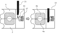
- the mold lock mechanism includes a lock bar 15 that descends in synchronization with the arrow 6, a rotary hook 16 that is fixed to the trunk mold 2, and a lock plate 17 that is fixed to the ring mold 5. .
- the lock bar 15 is lowered and the tip of the lock bar pushes the rotary hook 16, whereby the rotary hook 16 and the lock plate 17 are locked.
- the body mold 2 and the ring mold 5 are also locked in close contact.
- At the time of the pressing at least one of the lower mold 4a and the upper mold 4b of the molding die 4 for molding the glass optical component 11 is used. It is desirable that a hole 14 for removing air pushed out by the molten glass gob from a space corresponding to the shape to be 11 is provided. This is because when the molten glass gob is injected into the space through the molten glass inflow port 8, the air existing in the space escapes from the perforations, so that improvement in the dimensional accuracy of the optical component can be expected. In this case, it is desirable that the inner diameter of the perforations is 0.1 mm or more and 0.5 mm or less. This is because the diameter is sufficient to evacuate air and is small enough for molten glass to flow in.
- the second invention of the present application is a precise and complicated three-dimensional object using the glass optical component molding die according to any one of claims 1 to 7.
- a method for forming a glass optical component having a shape (1) A step of throwing a molten glass gob into the central part of the concave surface portion of the body mold provided with a lower mold of a molding die for molding a glass optical component on the outer edge part; (2) The ring mold is lowered and brought into close contact with the barrel mold, and the upper mold of the molding mold provided on the lower surface portion of the ring mold and the molding mold provided on the outer edge of the barrel mold.
- the method includes a step of taking out the solidified glass molded body formed between the body mold, the arrow mold, the ring mold, and the molding die and cutting the glass optical component formed between the molding dies.
- the steps (1) to (6) are sequentially performed.
- the pressing step it is necessary to continue until the temperature of the molten glass gob injected into the molding die 4 is equal to or lower than the annealing point of the glass.
- the annealing point is defined as a temperature at which the internal strain of the glass is substantially removed in 15 minutes at a temperature about 20 ° C. higher than the glass transition point. At this temperature, the glass is almost solidified.
- the manufacturing method of this invention if it does not fully press until the glass between molding dies solidifies, the dimension of an optical component will become unstable.
- Whether it has solidified at a temperature below the annealing point can be determined empirically by the elapsed time after pressing, but if strictness is required, install a thermocouple near the ring mold and adjust the temperature. It is better to measure. Further, since the glass molded body formed between the body mold, the arrow mold, the ring mold and the molding die is primarily obtained by this method, the glass optical component which is the final product from this molded body. The process of cutting is required. In addition, according to a request
- the weight of the molten glass gob thrown into the concave portion 3 of the barrel mold is 6 times or more, more preferably 8 times or more with respect to the weight of the glass molded body formed between the molding dies. Therefore, it should be 70 times or less.
- the flow of the molten glass gob can be sufficiently ensured, and the space 9 (or the space 9 and the additional space 12 provided outside the space 9) for obtaining the glass optical component through the molten glass inlet 8 is provided. Injection into the combined space) can be performed reliably. If it is less than 6 times, sufficient flow cannot be secured and molding of glass optical parts cannot be performed, and if it is more than 70 times, the molten glass gob overflows from between the ring mold and the arrow mold. It will be insufficient.
- a novel glass molding die and a glass molding method using the same a glass product having a precise and complicated three-dimensional shape that cannot be obtained by conventional molds and molding methods.
- Optical components can be molded.
- the basic embodiment does not require a special mold material and a non-oxidizing atmosphere such as a mold press method, and can be mass-produced or produced in a small quantity and a variety of products. It contributes.
- the molding die 1 for the glass optical component 11 according to the present invention is manufactured by cutting and grinding stainless steel according to a design drawing.
- a heat resistant alloy having higher durability may be used as necessary.
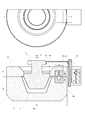
- FIG. 7 which is a design drawing (front view and plan view) of a molding die according to one embodiment, the glass optical component molding die of the present invention includes a barrel die 2, a molding die 4, and a ring. It consists of a mold 5 and an arrow 6.
- the barrel mold 2 is formed with a concave surface portion 3 into which a lump of molten glass (molten glass gob 7) made of a glass optical component material is charged, and a glass optical component 11 is formed on the peripheral edge thereof.
- a lower mold 4a for the molding die 4 is provided.
- the upper die 4 b of the molding die 4 is provided so as to face the lower die 4 a provided on the peripheral edge of the barrel die 2.
- the ring mold 5 first descends and comes into close contact with the body mold 2, and the lower mold 4 a and the ring mold of the molding die 4 at the periphery of the body mold 2.
- a space sandwiched between the lower die 5 and the upper die 4b of the molding die is formed.
- the arrow 6 having a convex surface part is lowered, and the molten glass gob 7 is pressurized from above.
- the molten glass gob rises along the inner surface of the concave portion 3 of the barrel die 2 and reaches the peripheral portion, and through the molten glass inlet 8, the lower mold 4 a and the upper mold of the molding die 4.
- the glass optical component 11 is formed by being injected into the space sandwiched between 4b.
- the molding die 1 for the glass optical component 11 according to the present invention has the characteristics as shown in FIGS. Features will be described with reference to each figure.
- FIG. 4 shows an example of the body mold 2 provided with four concentric circles.
- the upper mold 4b of the molding die 4 is provided concentrically on the lower surface side of the ring mold 5 and is simultaneously made by four presses of the glass.
- the mold structure is such that the optical component 11 can be molded.
- the number of molding dies 4 can be increased to 6 or 8. It can contribute to the improvement of productivity of the same optical component, and in some cases, by providing the molding dies 4 having different shapes, it is possible to mold a plurality of types of optical components with a single press.
- FIG. 3 shows the upper mold 4b of the molding die 4 provided on the lower surface side of the ring mold 5.
- the upper mold 4b is fixed to the ring mold 5 by bolting, for example, and can be attached and detached.
- the mold structure is as follows.
- the lower mold 4 a of the molding mold 4 has a mold structure (not shown) that can be attached and detached by an arbitrary method such as bolting.
- the lower mold 4a of the molding mold 4 and the upper mold 4b of the molding mold 4 can be exchanged to mold optical components of various shapes. These characteristics indicate that they are suitable for mass production or small-lot, multi-product production.
- FIG 4 shows a space 9 formed between the lower mold 4a and the upper mold 4b of the molding die 4, that is, a space 9 corresponding to the shape to be the glass optical component 11, and the space 9
- a mold structure in which an additional space 12 is further provided outside is shown.
- the additional space 12 is not provided, depending on the shape of the optical component, the molten glass gob 7 cannot flow into every corner of the space 9 corresponding to the shape to be the glass optical component 11, and a void is formed.
- the additional space 12 can surely flow into and fill the corner 9 at least in the space 9 corresponding to the shape of the glass optical component 11. Can now.
- FIG. 5 shows a mold structure provided with a mold lock mechanism 13 that holds the barrel mold 2 and the ring mold 5 in close contact with each other.
- a mold lock mechanism 13 that holds the barrel mold 2 and the ring mold 5 in close contact with each other.
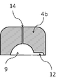
- FIG. 6 shows a perforation 14 for removing air pushed out by the molten glass gob 7 from the space 9 corresponding to the shape to be the glass optical component 11 during the pressing in the upper mold 4 b of the molding die 4.
- An example of a mold provided with a is shown.
- the inner diameter of the perforations 14 is 0.3 mm.
- a method for producing a glass optical component according to the present invention is a method for producing a glass optical component having a precise and complicated three-dimensional shape using a mold for molding a glass optical component having the above-mentioned characteristics. It is. Referring to FIG. 1 (and FIG. 4), (1) A molten glass gob 7 is introduced into the central part of the concave part 3 of the body mold 2 provided with the lower mold 4a of the molding die 4 for molding the glass optical component 11 at the outer edge part, (2) The ring die 5 is lowered and brought into close contact with the barrel die 2, and the upper die 4 a of the molding die 4 provided on the lower surface of the ring die and the molding die 4 provided on the outer edge of the barrel die.
- the lower die 4b is closely attached, and a space 9 corresponding to the shape of the glass optical component 11 is formed between the molding dies, (3)
- the molten glass gob 7 put in the central part of the concave part 3 of the trunk mold 2 is pressed from above with the arrow 6 having the convex part, (4)
- the pressing by the arrow 6 is continued, and the molten glass gob 7 is caused to flow so as to scoop up along the inner surface of the concave surface portion 3 of the body mold 2, and the space 9 formed between the molding dies (or
- the molten glass gob 7 is injected through the molten glass inlet 8 into the space 9 and the additional space 12 provided outside the space 9.
- the pressing step it is important to continue pressing until the temperature of the molten glass gob 7 injected into the molding die 4 is equal to or lower than the annealing point of the glass. Until the glass is solidified, for example, by pressing for about 10 to 30 seconds and continuing to apply pressure to the glass, a molded product with high dimensional accuracy can be obtained. Since the glass molded body 10 formed between the body mold 2, the arrow mold 6, the ring mold 5 and the molding die 4 is primarily obtained by this method, the final product is obtained from the molded body 10. The process which cut
- the weight of the molten glass gob 7 put into the concave surface portion 3 of the barrel mold 2 is 6 with respect to the weight of the glass molded body formed by the molding die 4. It is good that it is not less than double, more desirably not less than 8 times and not more than 70 times.
- the flow of the molten glass gob 7 can be sufficiently ensured, and the space 9 for obtaining the glass optical component 11 through the molten glass inlet 8 (or the space 9 and an additional provided outside the space 9).
- the injection into the space in which the target space 12 is combined can be performed reliably. If it is less than 6 times, sufficient flow cannot be secured and molding of glass optical parts cannot be performed, and if it is more than 70 times, the molten glass gob overflows from between the ring mold and the arrow mold. It will be insufficient.
- the molding die for glass optical component and the manufacturing method according to the present invention are provided on the periphery of the barrel die 2 and the lower surface of the ring die 5 by causing the molten glass gob 7 to flow by pressing with the barrel die 2 and the arrow die 6.
- the final product 11 is obtained by pouring into the space 9 formed by the molding die 4.
- it is completely different from the conventional direct press mold and manufacturing method in which the final molded product is simply press-molded directly between the barrel mold and the arrow mold.
- it has inherited the advantage that the cycle time of the pressing process of the direct pressing method is short, and it is a manufacturing method suitable for mass production of glass optical parts having precise and complicated three-dimensional shapes. it can.
- a precision three-dimensional glass optical component was molded using the molding method of the present invention described above.
- Table 1 a borosilicate glass having a general composition and a thermal expansion coefficient of about 55 ⁇ 10 ⁇ 7 / ° C. was used.
- the temperature of the molten glass gob when it was put into the barrel mold was about 1,000 ° C.
- the annealing point of this glass is about 500 degreeC.
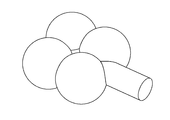
- Group 1 is the result of molding using the molding die whose design is shown in FIG. This is an example in which only one molding die is provided and a glass optical component having a complicated shape combining a plurality of free curved surfaces and planes as shown in FIG. 8 is molded.
- the weight W1 of the glass optical component to be molded is about 15 g.
- the glass optical component is made up of the molded glass between the barrel mold, the arrow mold, the ring mold and the mold, and the final product is released from the molded glass taken out. It is obtained by cutting out a portion of the glass optical component.
- the moldability and the appearance of the finished glass optical component were evaluated by changing the weight W2 of the molten glass gob thrown into the concave portion of the body mold.
- the pressing pressure by the arrow on the molten glass gob was about 3.1 MPa, and the pressing time was about 23 to 27 seconds depending on the weight of the molten glass gob.
- the molten glass gob When the weight of the molten glass gob is 100 g (W2 / W1 is about 7), the molten glass gob reaches the molten glass inlet 8 but is not sufficiently filled in the molding die, and a glass optical component can be obtained. could not. This is presumably because the molten glass gob has a small weight and heat capacity, so that the amount of heat is rapidly lost during the press, loses fluidity and solidifies.
- the arrow 6 cannot be lowered to a predetermined position, the balance of the thickness of the glass molded body 10 is lost, and there is a problem in releasability from the molding die.
- the glass molded body 10 including the optical component 11 was chipped. And in five examples whose weight of a molten glass gob was 200g to 900g, there was no problem in a moldability and the external appearance of the obtained glass optical components was also favorable.
- the molten glass gob is controlled to have a predetermined weight in a feeder furnace for molten glass. Then, the weight of the molten glass gob added was obtained by measuring the glass molded body 10 solidified after pressing with a scale. The same applies to the following embodiments.
- the molten glass gob is small in weight and heat capacity, so that the amount of heat is rapidly lost during pressing, fluidity is lost, and the molten glass gob is solidified before reaching the molten glass inlet.
- the molten glass passes through the molten glass inlet and is injected into the space for forming the glass optical component, but the amount is not sufficient.
- the molding of the optical component was incomplete.
- the molten glass gob When the molten glass gob is 500 g or more (W2 / W1 is about 8 or more), a sufficient amount of molten glass reaches the molten glass inflow port by climbing the concave portion of the barrel mold and forms a glass optical component The mold was filled and filled with the space, and the moldability was good. As a result, the appearance of the glass optical component was obtained as designed. In Group 2, even when the weight of the molten glass gob is 1,100 g, four times the amount of molten glass compared to Group 1 is injected into the molding die through the molten glass inflow port. I was able to do it without problems.
- Table 1 shows the results of tests conducted at six levels from 100 g to 1,100 g of the molten glass gob. When the molten glass gob was 100 g (W2 / W1 was about 1), the molten glass did not even reach the molten glass inlet, and it was impossible to mold a glass optical component.
- the molten glass gob is 300 g (W2 / W1 is about 3) and 500 g (W2 / W1 is about 4), the molten glass is injected into the space for forming the glass optical component through the molten glass inlet. However, the amount was not sufficient, and the molding of the glass optical component was incomplete.
- the molten glass gob is 700 g or more (W2 / W1 is about 6 or more)
- a sufficient amount of molten glass reaches the molten glass inflow port by climbing the concave portion of the barrel mold and forms a glass optical component The mold was filled and filled with the space, and the moldability was good. As a result, the appearance of the obtained glass optical component was obtained as designed. Even in Group 3, even if the weight of the molten glass gob is 1,100 g, 8 times the amount of molten glass compared to Group 1 is injected into the molding die through the molten glass inlet. I was able to do it without problems.
- the molten glass gob is pressed with an arrow mold while it has sufficient temperature and fluidity.
- the molten glass rises up the concave portion of the barrel mold and reaches the molten glass inlet, and is still injected between the molds through the molten glass inlet while maintaining an appropriate temperature and fluidity. It is considered that a glass optical component having a desired shape is obtained by being solidified by depriving the amount of heat, thereby obtaining a desired shape.
- the pressed molten glass gob in the concave part of the body mold is solidified, and both the moldability and the shape accuracy and mold release properties of the glass optical parts are It is considered to be in an appropriate state.
- Table 1 it is necessary to appropriately adjust the weight of the glass gob, the pressing pressure, and the pressing time with respect to the product weight.
- 1 is an example of a glass optical component molding die according to the present invention.
Landscapes
- Engineering & Computer Science (AREA)
- Chemical & Material Sciences (AREA)
- Physics & Mathematics (AREA)
- Manufacturing & Machinery (AREA)
- Materials Engineering (AREA)
- Organic Chemistry (AREA)
- General Physics & Mathematics (AREA)
- Optics & Photonics (AREA)
- Glass Compositions (AREA)
- Moulds For Moulding Plastics Or The Like (AREA)
Abstract
従来のダイレクトプレス法では、小型の精密ガラス部品の製造に際しては、溶融ガラスゴブの重量を一定に制御することが困難であり、ガラスゴブの重量のバラツキが大きくなってしまうことから、安定した精密成形ができないという問題があった。解決手段として、凹面部の外縁部にガラス製光学部品を成形するための成形金型の下型が設けられた胴型と、胴型の凹面部に組み合わされる凸面部を有する矢型と、前記矢型の外周部に配置され、前記ガラス製光学部品を成形するための成形金型の上型が設けられたリング型とから構成され、前記胴型の凹面部内に投入された溶融ガラスゴブが、前記矢型により上方からプレスされることにより、前記溶融ガラスゴブが、前記成形金型の下型と上型の間に形成される空間に注入されるようになっていることを特徴とするガラス製光学部品の成形用金型及びその成形用金型を用いたガラス製光学部品の製造方法を提供する。
Description
本発明は、立体形状を有するガラス製光学部品、具体的にはガラス製の両面非球面レンズ、異形レンズなどの精密でかつ複雑な立体形状を有する光学部品などに利用されるガラス製光学部品の成形用金型並びにその成形用金型を用いるガラス製光学部品の製造方法に関する。
近年の各種光源のLED化やLD化に伴ってレンズ形状品や光学部品の高精度化・複雑形状化が進んでいるが、これらに対応したガラスの成形用金型及びその金型を用いた大量生産あるいは少量多品種生産に適したガラスの成形方法が求められている。
従来、光学部品等の小さな立体形状を有するガラス成形品の成形方法としては、主にダイレクトプレス法、モールドプレス法、リヒートプレス法、射出成形法が試されてきた。
ダイレクトプレス法とは、溶融されたガラスゴブを金型内に投入し、プレス機にてプレス成形を行う最も典型的なプレス技術である。胴型、矢型及びリング型の間でガラスゴブを直接金型の形状に成形することから、ダイレクトプレス法と呼ばれる。大量生産方式としては、溶融炉から流出する溶融ガラス流から、製品重量に合わせてほぼ一定重量となるようシェアカット(刃で切断)された溶融ガラスゴブ(溶融したガラスの一塊)を、胴型(一対の金型のうち、下方にある凹面状の型)内に投入し、矢型(一対の金型のうち、上方にある凸面状の型)でプレスして、金型の形状に成形を行うことが一般的である。
矢型の外周部にはリング型が配置される。リング型は、矢型が下降してガラスゴブをプレスする際に、矢型よりも少し早めに下降して胴型に嵌合し、矢型をガイドしながら、プレスされるガラス製品の縁を形成する役割を担っている。
従来のダイレクトプレス技術には次のような欠点があった。
(1)小型の精密ガラス部品の製造に際しては、溶融ガラスゴブの重量を一定に制御することが困難であり、ガラスゴブの重量のバラツキが大きくなってしまうことから、安定した精密成形ができないという問題があった。即ち、ガラスゴブの重量変動を、そのまま製品の肉厚等の変動で吸収せざるを得ない成形方法であるため、形状精度の高い製品の成型は困難となるのである。
(2)小型で薄肉のガラス製光学部品を得ようとすると、プレスの際に溶融ガラスゴブが狭い金型の隙間を延びていく間に、金型によって急速に熱を奪われ、溶融ガラスゴブが薄く延びきらないうちにガラスが固化してしまうという問題があった。さらに小さいサイズのガラス製光学部品の場合には、もともとの溶融ガラスゴブ自体の保有熱量も少ないため、プレスの際に溶融ガラスゴブがすぐに冷えてしまうことになり、プレス成形中にガラスにヒビが入ったり破損してしまったりして、薄肉部分や細い部分を有する複雑な形状のガラス製光学部品を成形することは極めて困難であった。
(3)1,000℃前後の温度の溶融ガラスゴブを500℃前後の温度にある金型で成形するため、ガラスと金型との融着は防止されるものの、金型に接した溶融ガラスゴブの表面付近は急激に冷却されて固化する一方、ガラス内部は遅れて収縮・固化するために「ヒケ」と呼ばれる体積収縮に起因する一種の成形不良(形状及び寸法の不良)が発生し、高い形状精度が得られなかった。
(1)小型の精密ガラス部品の製造に際しては、溶融ガラスゴブの重量を一定に制御することが困難であり、ガラスゴブの重量のバラツキが大きくなってしまうことから、安定した精密成形ができないという問題があった。即ち、ガラスゴブの重量変動を、そのまま製品の肉厚等の変動で吸収せざるを得ない成形方法であるため、形状精度の高い製品の成型は困難となるのである。
(2)小型で薄肉のガラス製光学部品を得ようとすると、プレスの際に溶融ガラスゴブが狭い金型の隙間を延びていく間に、金型によって急速に熱を奪われ、溶融ガラスゴブが薄く延びきらないうちにガラスが固化してしまうという問題があった。さらに小さいサイズのガラス製光学部品の場合には、もともとの溶融ガラスゴブ自体の保有熱量も少ないため、プレスの際に溶融ガラスゴブがすぐに冷えてしまうことになり、プレス成形中にガラスにヒビが入ったり破損してしまったりして、薄肉部分や細い部分を有する複雑な形状のガラス製光学部品を成形することは極めて困難であった。
(3)1,000℃前後の温度の溶融ガラスゴブを500℃前後の温度にある金型で成形するため、ガラスと金型との融着は防止されるものの、金型に接した溶融ガラスゴブの表面付近は急激に冷却されて固化する一方、ガラス内部は遅れて収縮・固化するために「ヒケ」と呼ばれる体積収縮に起因する一種の成形不良(形状及び寸法の不良)が発生し、高い形状精度が得られなかった。
以上に述べたように、ダイレクトプレス法は大量生産には適しているものの、高い形状精度が得られず、また小さな複雑な形状品の成形にも適さないのである。
特許文献1には、2分割された一対の胴型の間で、溶融ガラス流出オリフィスから流出してくる溶融ガラスを挟むことによりガラスの成形を行う方法、また成形の際に胴型から押し出されるガラスを逃がす空間を設けたことを特徴とするガラス成形型が開示されている。しかしながら、通常のダイレクトプレス法と同じ理由により、形状精度の高い複雑な立体形状品を成形するには適さないと考えられる。
特許文献2には、非球面レンズの成形技術であって、溶融ガラスを成形金型でプレス成形して、底面に所定レンズ形状が形成されたカップ形状の成形品を形成し、さらにカップ形状成形品の底面の所定レンズ形状部分を再プレスし、続いてカップ形状成形品のまま底面の所定レンズ形状部分の加熱除歪を行った後に、所定レンズ形状部分から非球面レンズを切り取るようにしたことを特徴とする成形方法が開示されている。この方法も基本的には一次のプレス成形で形状がほぼ決まってしまう(この場合、再プレスは形状の微調整である)。
一方、モールドプレス法と呼ばれる高精度プレス技術が従来から知られている。モールドプレス法は、精密成形金型で、主に高精度な非球面ガラスレンズを製造する技術として開発されたものであるが、この成形技術は基本的に下記のプロセスからなり、ガラスに「ヒケ」を生じさせずに高精度の金型形状・面精度をガラスに転写させることに特徴がある。
(a)ガラスプリフォーム(最終製品に近似した形状・容積のガラス成形品)を準備する。
(b)ガラスと融着が生じない特殊な型材料を高精度に鏡面加工及び表面処理をする。
(c)非酸化性雰囲気中でガラスプリフォームと型とをガラスの軟化点近傍まで昇温させ、ガラスと型とをほぼ等しい温度にして、型によりガラスをプレスし、十分な時間にわたって加圧を維持しながら型温度をガラス転移点以下(ガラスが構造的に安定する温度以下)になるまで降温する。
(a)ガラスプリフォーム(最終製品に近似した形状・容積のガラス成形品)を準備する。
(b)ガラスと融着が生じない特殊な型材料を高精度に鏡面加工及び表面処理をする。
(c)非酸化性雰囲気中でガラスプリフォームと型とをガラスの軟化点近傍まで昇温させ、ガラスと型とをほぼ等しい温度にして、型によりガラスをプレスし、十分な時間にわたって加圧を維持しながら型温度をガラス転移点以下(ガラスが構造的に安定する温度以下)になるまで降温する。
しかし、このモールドプレス技術には下記の欠点があった。
(1)ガラスの軟化点近傍での加熱・加圧処理であるため、基本的にガラスプリフォームに近似した形状のものしか成形できず、製品の形状及びサイズに限界がある。
(2)非酸化性雰囲気中での加熱、冷却に長時間を要するため生産性が悪く、大量生産には不利である。
(3)特殊な型材料を必要とする。これは型材とガラスとが長時間にわたって接触することから、両者が反応して融着等を起こさないようにするためであり、上記の非酸化性雰囲気を利用するのも同じ理由によるものである。
(1)ガラスの軟化点近傍での加熱・加圧処理であるため、基本的にガラスプリフォームに近似した形状のものしか成形できず、製品の形状及びサイズに限界がある。
(2)非酸化性雰囲気中での加熱、冷却に長時間を要するため生産性が悪く、大量生産には不利である。
(3)特殊な型材料を必要とする。これは型材とガラスとが長時間にわたって接触することから、両者が反応して融着等を起こさないようにするためであり、上記の非酸化性雰囲気を利用するのも同じ理由によるものである。
このように、モールドプレス法は、ダイレクトプレス法とは逆に、非球面ガラスレンズなどの小さな高精度形状品の成形には適しているものの、ガラスプリフォーム形状から大きく逸脱した複雑な形状品の成形には適さないのである。
特許文献3には、ガラス素材を高精度の光学レンズ等の成形品に加工する成形方法であって、成形型の温度を被成形ガラスの転移点以上、軟化点以下で一定に保ち、この型内に流動性を有するガラス素材を搬入して、これを加圧成形し、そして、この状態を成形されたガラスの温度分布が均一化されるまで、例えば、20秒以上保持することによって、ヒケの発生を除去し、公差3/100mm以下という極めて寸法精度の高いレンズ等の光学部品を得る方法が開示されている。
また、特許文献4には、ガラス転移温度付近の一定温度に保持された成形型内に、加熱軟化したガラス素材を搬入して短時間加圧成形した後、型圧を徐々に減圧し、または型の温度を徐々に低下し、あるいは型圧と型温度とを徐々に下げながら成形を行うガラス光学部品の高精密成形方法が開示されている。
しかしながら、これらモールドプレス法においても、プレス温度がガラスの軟化点近傍かそれ以下であるためにガラスの流動性が十分でなく、複雑な形状品の成形が困難であること、また、プレス時間がダイレクトプレス法より長時間に及ぶことにより大量生産には基本的に適さないなどの欠点があった(非特許文献1)。
リヒートプレス法は、一旦板状や棒状に成形されたガラス品を再度加熱したのち、再度プレス成形を行う方法である。粗形状品の形状の微調整や精度の向上を主目的とするものであるので、複雑な立体形状品を高精度で成形するには適さない成形方法である。
特許文献5には、ガラス基板の成形精度を向上させることを目的として、溶融ガラスを所定形状に固化成形するダイレクトプレス工程と、それによって得られたガラス基板を加熱条件下で再プレスして形状の微調整もしくは変形を行うリヒートプレス工程とからなる高精度ガラス基板の作製方法が開示されている。
また、特許文献6には、溶融ガラスを粗プレス成形してV溝基板を得たのち、次いで得られたV溝基板を再加熱して該V溝基板が軟化する温度まで昇温し、精密に形状の微調整を行うリヒートプレス成形によるV溝基板の製造方法が開示されている。
これら技術についても、形状精度の高い複雑な立体形状品を成形するには適さないと考えられる。
射出成形法は、主として樹脂の成形に用いられる成形法であり、溶融温度が高く、かつ温度によって急激に粘性が変化にするガラスには基本的には適さない成形方法である。ガラスは粘性が高く、高温にしないと射出成形に適した粘性にまで下がらず、十分な流動性が得られないからである。
特許文献7には、自己消耗型プランジャを加圧し前進させることによって、溶融状態の成形材料を温度制御された加熱シリンダの先端に配設された射出ノズルから射出させ、成形型内に充填する技術が開示されている。ガラス製の自己消耗型プランジャを別工程で作製しなければならない点、自己消耗型プランジャの温度コントロールが煩雑な点、そのため量産性に劣る点等において問題があり、また複雑な立体形状品を成形するには適さないと考えられる。
特許文献8には、500℃以下の融点を持つ低融点ガラスを原料として、プラスチックと同様に射出成形機によってガラス成形品を得る技術が開示されている。ガラス原料を事前に溶解させることなく、小片の低融点ガラス成形材料を射出成形機のホッパから供給し、直接射出成形機のシリンダバレル内で加熱するとともにスクリューの回転によって溶融させ、シリンダバレル先端のノズルから金型のキャビティ内に射出し、冷却固化させて成形品とする技術である。しかしながら、特殊な低融点ガラスを対象としており、ソーダ石灰ガラスやホウケイ酸ガラスなどの融点が高く粘性も高い一般的なガラスの成形には適していない。
特許文献9には、溶融ガラスを成形型に供給して射出成形を行った後に、ガラスの屈服点近傍の粘度状態に保つように温度調整されたプレスステージに移行して、温度低下に伴う熱収縮による成形型内でのヒケの発生を防止するために、さらにプレスすることによって形状の修正を行う技術が開示されている。
このような技術でも、粘性が高くかつ温度による粘性の変化が大きいガラスでは、射出成形による一工程での成形(いわゆる一発成形)は困難であり、形状精度の高い複雑な立体形状品を成形するには適さないと考えられる。
特許文献10は、モールドプレス法と射出成形法を掛け合わせたようなガラスの成形方法を開示している。トランスファ室で700~800℃に加熱して軟化させたガラスをプレスして、トランスファ室の周囲に配置された製品用の金型(モールド)内に、湯道を通して押し出して充填することを特徴とする成形方法である。すべての金型はガラス状炭素で形成されている。本成形方法は基本的にはモールドプレス法の影響を大きく受けるものであり、プレス温度がガラスの軟化点近傍かそれ以下であるためにガラスの流動性が十分でなく複雑な形状品の成形が困難であること、プレスが長時間に及ぶことにより大量生産には基本的に適さないこと、並びに特殊な金型材料が必要なことなどの欠点がある。
特許文献11は、特許文献10の欠点を解決するために考案されたガラスの成形方法を開示しており、射出成形法の一種と言えるものである。本成形方法は、基本的には特許文献10に開示されているトランスファ室をガラス溶融炉に置き換えたものであり、トランスファ室内でガラス塊を軟化点付近に加熱してその軟化したガラスをモールドプレス法によって押し出していた工程を、ガラス溶融炉から直接低粘性の溶融ガラスを流出させて型内に充填させかつその後さらに型内でプレス成形を行う工程に置き換えている。特許文献10に開示されている技術に比べて、全工程を通してガラスの温度を高く維持できているためガラスの流動性に関しては改善されていると考えられる。しかし、成形装置及び金型の上部にガラス溶融炉を配置しなければならず、設備的及び操作・作業上の問題があると考えられる。
特許文献12は、樹脂製の光学素子の成形方法に関する技術である。樹脂の溶融温度は200~300℃であって、低温で十分な流動性が得られるが、本技術を溶融温度が高く、粘性も高く(すなわち、流動性が悪い)、かつ温度変化による粘性の変化が大きいガラスに直接適用するのは困難である。
New Glass 72, Vol. 19, No.1, p.65(2004)
従来のダイレクトプレス法では、小型の精密ガラス部品の製造に際しては、溶融ガラスゴブの重量を一定に制御することが困難であり、ガラスゴブの重量のバラツキが大きくなってしまうことから、安定した精密成形ができないという問題があった。
従来のモールドプレス法は、ダイレクトプレス法とは逆に、非球面ガラスレンズなどの小さな高精度形状品の成形には適しているものの、ガラスプリフォーム形状から大きく逸脱した複雑な形状品の成形には適さないのである。
リヒートプレス法は、既に粗成形された板状や棒状のガラスプリフォームの表面を微調整したり、精度の向上を主目的とするものであって、やはり形状精度の高い複雑な立体形状品を成形するには適さない。
射出成形法は、樹脂材料の立体成型に適した方法であって、広く普及しているが、粘性が高くかつ温度による粘性の変化が大きいガラスでは、射出成形による一工程での成形は困難であり、形状精度の高い複雑な立体形状品を成形するには適さない。
本出願に係る発明の目的は、精密でかつ複雑な立体形状を有するガラス製光学部品を成形することができる新規なガラスの成形用金型及びその金型を用いた大量生産あるいは少量多品種生産に適したガラスの成形方法を提供することにある。
前記従来の課題を解決するため本願の第一の発明は、精密かつ複雑な立体形状を有するガラス製光学部品を成形するための金型であって、凹面部の外縁部に前記ガラス製光学部品を成形するための、少なくとも一対の成形金型の下型が設けられた胴型と、前記胴型の凹面部に組み合わされる凸面部を有する矢型と、前記矢型の外周部に配置され、前記ガラス製光学部品を成形するための、少なくとも一対の成形金型の上型が設けられたリング型とから構成され、前記胴型の凹面部内に投入された溶融ガラスゴブが、前記凸面部を有する矢型により上方からプレスされることにより、前記溶融ガラスゴブが、前記少なくとも一対の成形金型の下型と上型の間に形成される空間に注入されるようになっていることを特徴とするガラス製光学部品の成形用金型を開示する。
ここで、精密かつ複雑な立体形状を有するガラス製光学部品とは、両面非球面レンズ、異形レンズ、複雑な立体形状を有する光学部品などのことであって、本発明によれば、例えばほとんど平坦な面を持たず、両面にグリッド状の溝が形成されているなど、単純な凹レンズや凸レンズを成形するよりもはるかに困難度の高いガラス製光学部品を成形できる金型を提供できる。
本発明の成形用金型は、胴型、矢型、リング型及び成形金型の4つの型から構成される。胴型の主要部は凹面部であるが、胴型の周縁部には成形金型の下型が設けられ、リング型の下面側には、成形金型の上型が設けられている。従来のダイレクトプレス用金型は、胴型と矢型の間で、又は胴型と矢型とリング型の間で最終成形品をプレス成形するのに対して、本発明では、胴型と矢型によるプレスは、溶融ガラスゴブに流動を生じさせるものであって、これにより、胴型の周縁部と矢型の下面に設けられた成形金型によって形成される空間に溶融ガラスゴブを注入して、成形金型間で最終製品を得るという点で全く異なる。
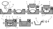
本発明の成形用金型の構成と機能を、図1を用いて説明する。本発明のガラス製光学部品成形用金型1は、胴型2、成形金型4、リング型5及び矢型6から構成される。胴型2の凹面部3には、ガラス製光学部品の材料である溶融ガラスの一塊(溶融ガラスゴブ7)が投入される。一方、矢型6は凸面部を有し、前記溶融ガラスゴブ7を上方から加圧するためのものである。本発明は、上記したように、従来のダイレクトプレス法とは異なり、胴型2と矢型6の金型の形状をそのまま転写して成形品を得るものはなく、胴型2に投入された溶融ガラスゴブ7が矢型6によってプレスされた際に、胴型の凹面部3に沿ってせりあがって周縁部に到達し、溶融ガラス流入口8を通じて、周縁部に設けられた成形金型4の下型4aとリング型5の下面に設けられた成形金型の上型4bの間の空間に、溶融ガラスが注入され満たされることによって、ガラス製光学部品11が形成される。
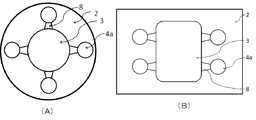
ここで、前記ガラス製光学部品11を成形するための前記成形金型4の下型4aが、図2(A)に示したように、前記胴型2の凹面部の外縁部に、凹面部の中心軸を中心に同心円状に複数個設け、かつ前記成形金型4の上型4bが、前記同心円状に複数個設けられた下型4aの位置に合わせて、前記リング型5に同じく同心円状に複数個設け、一度のプレスにより、複数個の前記ガラス製光学部品11を成形できるようになっていることが望ましい。このようにすることにより、同一光学部品の生産性を向上できるし、場合によっては、異なる形状の成形金型4を設けることにより、一度のプレスで複数種の光学部品を成形することもできる。
但し、複数の成形金型を、必ずしも同心円状に配置することに限られるものではなく、例えば、平面視略長方形状の胴型を用い、該胴型に平面視略長方形状の凹面部を設け、該凹面部の周囲に複数の成形金型を並列に配置してもよい(図2(B))。
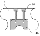
さらに、前記ガラス製光学部品11を成形するための成形金型4の下型4aは、胴型2にはめ込まれることにより胴型と一体化でき、また前記成形金型4の上型4bは、リング型5にはめ込まれることによりリング型と一体化でき、かつ成形金型の下型4aは、胴型2から取り外し可能な構造であり、また前記成形金型の上型4bは、リング型5から取り外し可能な構造であり、前記ガラス製光学部品11の形状に合わせて前記成形金型4の下型4a及び前記成形金型4の上型4bを交換できるようになっていることが望ましい。同一の胴型2、矢型6及びリング型5を用いながら、種々の光学部品を製造することが可能となるからである。成形金型の着脱機構の一例を図3に示す。この場合、成形金型は、ボルト締めによってリング型に固定されている。
前記プレスの際に、前記ガラス製光学部品11を成形するための前記成形金型4の下型4aと上型4bの間に形成される空間9は、前記ガラス製光学部品11となる形状に対応した空間であるが、それに加え、図4に示したように、該空間の外側に、前記溶融ガラスゴブが流入できる付加的空間12を有していると、溶融ガラスゴブの該空間9への注入が確実になることから、望ましい。こうすることによって該空間9に空隙ができてガラス製光学部品の形状が不良になることを防止できるからである。
また、前記プレスの際に、図5に示したように、前記胴型2と前記リング型5とを密着し保持させる金型ロック機構13を備えていることが望ましい。こうすることにより、胴型とリング型の間に隙間ができることによるガラス製光学部品の寸法不良の発生を防止できるからである。図5において、金型ロック機構は、矢型6と同期して下降するロックバー15と、胴型2に固定される回転フック16およびリング型5に固定されるロックプレート17とで構成される。矢型6と同期してロックバー15が下降し、ロックバー先端が回転フック16を押し回すことにより、回転フック16とロックプレート17がロックされる。これにより、胴型2及びリング型5も密着した状態でロックされる。
さらに、図6に示したように、前記ガラス製光学部品11を成形するための前記成形金型4の下型4a及び上型4bの少なくとも一方に、前記プレスの際に、前記ガラス製光学部品11となる形状に対応した空間から、前記溶融ガラスゴブによって押し出される空気を抜くための穿孔14が設けられているのが望ましい。溶融ガラスゴブが溶融ガラス流入口8を通じて該空間に注入される際に、該空間に存在していた空気が穿孔から抜けることにより、光学部品の寸法精度の向上が期待できるからである。この場合、前記穿孔の内径が0.1mm以上で0.5mm以下であることが望ましい。空気を抜くには十分な径であり、溶融ガラスが流入するには十分に小さいからである。
前記従来の問題点を解決するために本願の第二の発明は、請求項1乃至7のいずれか一項に記載のガラス製光学部品の成形用金型を用いた、精密でかつ複雑な立体形状を有するガラス製光学部品の成形方法であり、
(1)外縁部にガラス製光学部品を成形するための成形金型の下型が設けられた胴型の凹面部中央部に、溶融ガラスゴブを投入する工程と、
(2)前記リング型を下げて前記胴型に密着させ、該リング型の下面部に設けられた前記成形金型の上型と該胴型の外縁部に設けられた該成形金型の下型を密着させ、該成形金型間に前記ガラス製光学部品の形状に対応した空間を形成する工程と、
(3)前記胴型の凹面部中央部に投入された前記溶融ガラスゴブを、凸面部を有する矢型で上方からプレスする工程と、
(4)前記矢型によるプレスを継続して、前記溶融ガラスゴブを、前記胴型の凹面部の内面に沿って這い上がるように流動させ、前記成形金型間に形成された空間内に、溶融ガラス流入口を通して、溶融ガラスゴブを注入する工程と、
(5)前記成形金型に注入された溶融ガラスゴブ温度が、このガラスの徐冷点以下となって固化した後、前記矢型とリング型を順に上方に引き上げる工程と、
(6)前記胴型、矢型、リング型及び成形金型の間に形成された固化ガラス成形体を取り出し、前記成形金型間に形成されたガラス製光学部品を切断する工程
とからなることを特徴とする精密かつ複雑な立体形状を有するガラス製光学部品の製造方法を開示する。
(1)外縁部にガラス製光学部品を成形するための成形金型の下型が設けられた胴型の凹面部中央部に、溶融ガラスゴブを投入する工程と、
(2)前記リング型を下げて前記胴型に密着させ、該リング型の下面部に設けられた前記成形金型の上型と該胴型の外縁部に設けられた該成形金型の下型を密着させ、該成形金型間に前記ガラス製光学部品の形状に対応した空間を形成する工程と、
(3)前記胴型の凹面部中央部に投入された前記溶融ガラスゴブを、凸面部を有する矢型で上方からプレスする工程と、
(4)前記矢型によるプレスを継続して、前記溶融ガラスゴブを、前記胴型の凹面部の内面に沿って這い上がるように流動させ、前記成形金型間に形成された空間内に、溶融ガラス流入口を通して、溶融ガラスゴブを注入する工程と、
(5)前記成形金型に注入された溶融ガラスゴブ温度が、このガラスの徐冷点以下となって固化した後、前記矢型とリング型を順に上方に引き上げる工程と、
(6)前記胴型、矢型、リング型及び成形金型の間に形成された固化ガラス成形体を取り出し、前記成形金型間に形成されたガラス製光学部品を切断する工程
とからなることを特徴とする精密かつ複雑な立体形状を有するガラス製光学部品の製造方法を開示する。
既に詳述してきたように、本発明は、前記成形用金型を用いた精密でかつ複雑な立体形状を有するガラス製光学部品を製造するに際し、前記(1)から(6)の工程を順に行うが、プレス工程では、前記成形金型4に注入された溶融ガラスゴブの温度が、このガラスの徐冷点以下になるまで、継続する必要がある。徐冷点とは、ガラス転移点より約20℃高い温度で、ガラスの内部歪が15分間で実質的に除去される温度と定義されているが、この温度ではガラスはほぼ固化している。そして、本発明の製造方法では、成形金型間にあるガラスが固化するまでプレスを十分に行わないと、光学部品の寸法が不安定になってしまう。徐冷点以下の温度となって固化したかどうかは、プレス後の経過時間で経験的に把握できるが、厳密を要する場合は、リング型の成形金型近傍に熱電対を設置して温度を測定するのがよい。また、この方法によって一次的に得られるのは、胴型、矢型、リング型及び成形金型の間に形成されたガラス成形体であるので、この成形体から最終製品であるガラス製光学部品を切断する工程が必要となる。なお、要求に応じて、切断後に切断面や端面の研削加工及び研磨加工を行う場合もある。
この製造方法においては、前記成形金型間に形成されるガラス成形体の重量に対して、前記胴型の凹面部3に投入される溶融ガラスゴブの重量が6倍以上、より望ましくは8倍以上で、70倍以下であるのがよい。このような重量比にすることにより、溶融ガラスゴブの流動が十分に確保でき、溶融ガラス流入口8を通してガラス製光学部品を得る空間9(あるいは空間9とその外側に設けられた付加的空間12を合わせた空間)への注入が確実に行える。6倍以下では、流動が十分に確保できず、ガラス製光学部品の成形が行えず、70倍以上では、溶融ガラスゴブがリング型と矢型の間からからあふれ出してしまい、その結果プレス圧力が不足してしまう。
本発明の技術によれば、新規なガラスの成形用金型及びそれを用いたガラスの成形方法により、従来の金型や成形方法では得られなかった精密でかつ複雑な立体形状を有するガラス製光学部品を成形することができる。また、基本的な実施形態においてモールドプレス法のような特殊な型材料及び非酸化性雰囲気を必要としないばかりか、大量生産あるいは少量多品種生産をすることが可能であり、産業の発展に大きく貢献するものである。
本発明におけるガラス製光学部品11の成形用金型1は、ステンレス鋼を設計図面通りに切削・研削することにより製作される。成形金型4については、必要に応じて、より耐久性の高い耐熱合金を用いてもよい。一実施態様の成形用金型の設計図(正面図および平面図)を図7に示したように、本発明のガラス製光学部品成形用金型は、胴型2、成形金型4、リング型5及び矢型6から構成される。胴型2には、ガラス製光学部品の材料からなる溶融ガラスの一塊(溶融ガラスゴブ7)が投入される凹面部3が形成されており、さらにその周縁部にはガラス製光学部品11を成形するための成形金型4の下型4aが設けられている。
一方、リング型5の下面側には、成形用金型4の上型4bが、胴型2の周縁部に設けられた下型4aと相対するように設けられている。胴型2の凹面部3に溶融ガラスゴブ7が投入されると、まずはリング型5が降下して胴型2に密着し、胴型2の周縁部の成形金型4の下型4aとリング型5の下面部の成形金型の上型4bとの間に挟まれた空間が形成される。リング型5の降下に続いて凸面部を有する矢型6が降下して、前記溶融ガラスゴブ7が上方から加圧される。溶融ガラスゴブは、十分な流動性を維持したまま、胴型2の凹面部3内面に沿ってせりあがって周縁部に到達し、溶融ガラス流入口8を通じて成形金型4の下型4aと上型4bとの間に挟まれた空間内に注入されることによって、ガラス製光学部品11が形成される。この際、胴型2とリング型5の密着を確実にするために、後述する金型ロック機構13を用いるのがよい。
さらに本発明によるガラス製光学部品11の成形用金型1は、図2から図6に示すような特徴を有している。それぞれの図を用いて特徴を説明する。
図2(A)は、前記ガラス製光学部品11を成形するための前記成形金型4の下型4aが、前記胴型2の凹面部3の外縁部に、凹面部3の中心軸を中心に同心円状に4個設けられている胴型2の例を示したものである。これら4個の下型4aの位置に合わせて、リング型5の下面側には成形用金型4の上型4bが同心円状に設けられており、一度のプレスによって同時に4個の前記ガラス製光学部品11を成形できる金型構造としている。同様に成形金型4の数を6個、8個と増やすこともできる。同一光学部品の生産性の向上に貢献でき、場合によっては、異なる形状の成形金型4を設けることにより、一度のプレスで複数種の光学部品を成形することもできる。
図3は、リング型5の下面側に設けられた成形用金型4の上型4bを示したものであるが、上型4bは例えばボルト締めによってリング型5に固定されており着脱が可能である金型構造としている。同様に、胴型2においても成形金型4の下型4aはボルト締めなどの任意の方法によって着脱が可能な金型構造となっており(図示せず)、同一の胴型2、矢型6及びリング型5を用いながら、前記成形金型4の下型4a及び前記成形金型4の上型4bを交換することによって種々の形状の光学部品を成形することを可能としている。これら特徴は、大量生産あるいは少量多品種生産に適していることを示すものである。
図4は、成形金型4の下型4aと上型4bとの間に挟まれて形成された空間9、即ち前記ガラス製光学部品11となる形状に対応した空間9と、その空間9の外側にさらに付加的空間12を設けた金型構造を示している。付加的空間12を設けない場合、光学部品の形状によっては、前記溶融ガラスゴブ7が前記ガラス製光学部品11となる形状に対応した空間9の隅々にまで流入できずに空隙ができ不良品となる可能性があったが、前記付加的空間12を設けることで少なくとも前記ガラス製光学部品11となる形状に対応した空間9には前記溶融ガラスゴブ7を隅々にまで確実に流入・充填させることができるようになった。
図5は、前記胴型2と前記リング型5とを密着し保持させる金型ロック機構13を設けた金型構造とすることを示している。溶融ガラスゴブが注入されることによって胴型2とリング型5の間が拡げられて隙間ができやすくなるが、金型ロック機構13を設けることによって隙間を抑え、ガラス製光学部品11の寸法不良の発生を防止することができる。
図6は、前記成形金型4の上型4bに、前記プレスの際に前記ガラス製光学部品11となる形状に対応した空間9から、前記溶融ガラスゴブ7によって押し出される空気を抜くための穿孔14を設けた金型の一例を示している。空間9に存在していた空気が穿孔14から抜け出る金型構造とすることにより、形状不良品の発生防止や光学部品の寸法精度の向上が期待できる。図6では、前記穿孔14の内径は0.3mmとした。
次に、本発明によるガラス製光学部品の製造方法は、上述の各特徴を有するガラス製光学部品の成形用金型を用いた、精密でかつ複雑な立体形状を有するガラス製光学部品の製造方法である。図1(及び図4)を用いて説明すると、
(1)外縁部にガラス製光学部品11を成形するための成形金型4の下型4aが設けられた胴型2の凹面部3の中央部に、溶融ガラスゴブ7を投入し、
(2)リング型5を下げて胴型2に密着させ、該リング型下面部に設けられた成形金型4の上型4aと、該胴型の外縁部に設けられた該成形金型4の下型4bを密着させ、該成形金型間にガラス製光学部品11の形状に対応した空間9を形成し、
(3)胴型2の凹面部3の中央部に投入された溶融ガラスゴブ7を、凸面部を有する矢型6で上方からプレスし、
(4)前記矢型6によるプレスを継続して、溶融ガラスゴブ7を、胴型2の凹面部3の内面に沿って這い上がるように流動させ、成形金型間に形成された空間9(あるいは空間9とその9の外側に設けられた付加的空間12を合わせた空間)内に、溶融ガラス流入口8を通して、溶融ガラスゴブ7を注入し、
(5)成形金型4に注入された溶融ガラスゴブ温度が、このガラスの徐冷点以下の温度となって固化した後、矢型6とリング型5を順に上方に引き上げ、
(6)胴型2、矢型6、リング型5及び成形金型4の間に形成された固化ガラス成形体10を取り出し、成形金型間に形成されたガラス製光学部品11を切断することにより、精密かつ複雑な立体形状を有するガラス製光学部品を製造することができる。
(1)外縁部にガラス製光学部品11を成形するための成形金型4の下型4aが設けられた胴型2の凹面部3の中央部に、溶融ガラスゴブ7を投入し、
(2)リング型5を下げて胴型2に密着させ、該リング型下面部に設けられた成形金型4の上型4aと、該胴型の外縁部に設けられた該成形金型4の下型4bを密着させ、該成形金型間にガラス製光学部品11の形状に対応した空間9を形成し、
(3)胴型2の凹面部3の中央部に投入された溶融ガラスゴブ7を、凸面部を有する矢型6で上方からプレスし、
(4)前記矢型6によるプレスを継続して、溶融ガラスゴブ7を、胴型2の凹面部3の内面に沿って這い上がるように流動させ、成形金型間に形成された空間9(あるいは空間9とその9の外側に設けられた付加的空間12を合わせた空間)内に、溶融ガラス流入口8を通して、溶融ガラスゴブ7を注入し、
(5)成形金型4に注入された溶融ガラスゴブ温度が、このガラスの徐冷点以下の温度となって固化した後、矢型6とリング型5を順に上方に引き上げ、
(6)胴型2、矢型6、リング型5及び成形金型4の間に形成された固化ガラス成形体10を取り出し、成形金型間に形成されたガラス製光学部品11を切断することにより、精密かつ複雑な立体形状を有するガラス製光学部品を製造することができる。
上記の工程の中で、プレス工程において、前記成形金型4に注入された溶融ガラスゴブ7の温度がこのガラスの徐冷点以下になるまで、プレスを継続することが重要である。ガラスが固化するまで、例えば10秒~30秒程度の間、プレスを行ってガラスに圧力を加え続けることで、寸法精度の高い成形品が得られる。なお、この方法によって一次的に得られるのは、胴型2、矢型6、リング型5及び成形金型4の間に形成されたガラス成形体10であるので、この成形体10から最終製品であるガラス製光学部品11を切断する工程が必要である。また、要求に応じて、切断後に切断面や端面の研削加工及び研磨加工を行う場合もある。
本発明によるガラス製光学部品の製造方法においては、前記成形金型4によって形成されるガラス成形体の重量に対して、前記胴型2の凹面部3に投入される溶融ガラスゴブ7の重量が6倍以上、より望ましくは8倍以上で、70倍以下であるのがよい。このような重量比にすることにより、溶融ガラスゴブ7の流動が十分に確保でき、溶融ガラス流入口8を通してガラス製光学部品11を得る空間9(あるいは空間9とその9の外側に設けられた付加的空間12を合わせた空間)への注入が確実に行える。6倍以下では、流動が十分に確保できず、ガラス製光学部品の成形が行えず、70倍以上では、溶融ガラスゴブがリング型と矢型の間からからあふれ出してしまい、その結果プレス圧力が不足してしまう。
本発明によるガラス製光学部品の成形用金型及び製造方法は、胴型2と矢型6によるプレスによって溶融ガラスゴブ7を流動させて、胴型2の周縁部とリング型5の下面に設けられた成形金型4によって形成される空間9に注入して最終製品11を得る。その点で、単純に胴型と矢型とで最終成形品を直接プレス成形する従来のダイレクトプレス用金型及び製造方法とは全く異なるが、胴型2と矢型6とで溶融ガラスゴブ7をプレスするという点では、ダイレクトプレス法のプレス工程のサイクルタイムが短いという利点を受け継いでおり、精密でかつ複雑な立体形状を有するガラス製光学部品を大量生産するのに適した製造方法ということができる。
上述した本発明の成形用金型を用いて、上述した本発明の成形方法を用いて、精密立体形状のガラス製光学部品を成形した。それら実施例をまとめて表1に示す。ガラスとしては、熱膨張係数が約55x10-7/℃の、一般的な組成のホウ珪酸ガラスを用いた。胴型に投入される際の溶融ガラスゴブの状態での温度は約1,000℃であった。なお、このガラスの徐冷点は約500℃である。

グループ1は、図7に設計図を示した成形用金型を用いた成形結果である。成形金型が1個だけ設けられていて、図8に示したような複数の自由曲面や平面を組み合わせた複雑形状のガラス製光学部品を成形した例である。成形されるガラス製光学部品の重量W1は約15gである。既に述べたように、ガラス製光学部品は、胴型、矢型、リング型及び成形金型の間で成形されたガラスをこれらの型から離型し、取り出した成形されたガラスから、最終製品となるガラス製光学部品の部分を切り出すことによって得られる。グループ1の一連の試験では、胴型の凹面部に投入する溶融ガラスゴブの重量W2を変えて成形性や出来上がったガラス製光学部品の外観を評価した。溶融ガラスゴブに対する矢型によるプレス圧力は約3.1MPaで、プレス時間は溶融ガラスゴブの重量に応じて約23~27秒プレスした。
溶融ガラスゴブの重量が100g(W2/W1は約7)の場合は、溶融ガラスゴブは溶融ガラス流入口8には到達するものの、成形金型には十分に満たされず、ガラス製光学部品を得ることができなかった。これは、溶融ガラスゴブの重量及び熱容量が小さいために、プレス中に急激に熱量を奪われ、流動性を失くし、固化するためと考えられる。逆に、溶融ガラスゴブの重量を1,100g(W2/W1は約73)まで増やすと、投入後に矢型でプレスした際、ガラス成形体10を形成するための胴型2、リング型5、矢型6及び成形金型4で作られる空間の容積に対し、溶融ガラスゴブの容積が大きすぎて、リング型5と矢型6の隙間に溶融ガラスゴブ7が入り込み、矢型6の下降を妨げることとなって、プレスを継続することができなかった。この場合には、矢型6が所定の位置まで下降しきれないため、ガラス成形体10の肉厚のバランスがくずれ、成形用金型との離型性にも問題が生じた結果、ガラス製光学部品11を含めたガラス成形体10には欠けが生じていた。そして、溶融ガラスゴブの重量が200gから900gまでの5つの例では、成形性に問題がなく、得られたガラス製光学部品の外観も良好であった。なお、ここで、溶融ガラスゴブは、溶融ガラスのフィーダー炉において、所定の重量になるよう制御されている。そして、投入された溶融ガラスゴブの重量は、プレス後に固化したガラス成形体10を秤で測定して求めた。以降の実施例においても同様である。
グループ2は、グループ1と同じ複数の自由曲面や平面を組み合わせた複雑形状のガラス製光学部品を成形した結果であるが、グループ2では、図2(A)に示したような胴型を利用した成形用金型を用いて、一度のプレスで4個のガラス製光学部品を製造した。この場合、4個のガラス製光学部品の総重量は4x15g=60gとなる。溶融ガラスゴブの重量を100gから1,100gまで6つの水準で試験を行った結果を表1に示した。溶融ガラスゴブが100g(W2/W1は約2)では、溶融ガラスは溶融ガラス流入口にすら到達せず、ガラス製光学部品を成形することは不可能であった。これは、やはり、溶融ガラスゴブの重量及び熱容量が小さいために、プレス中に急激に熱量を奪われ、流動性を失くし、溶融ガラス流入口に到達する前に固化するためと考えられる。溶融ガラスゴブを300g(W2/W1=5)とした場合は、溶融ガラスは溶融ガラス流入口を通過してガラス製光学部品を成形する空間には注入されるが、その量が十分ではなく、ガラス製光学部品の成形は不完全なものであった。溶融ガラスゴブが500g以上(W2/W1は約8以上)の場合は、十分な量の溶融ガラスが胴型の凹面部をせりあがって溶融ガラス流入口に到達し、ガラス製光学部品を成形する空間に注入され、その空間を満たして、成形性が良好であった。その結果、ガラス製光学部品の外観も設計通りのものが得られた。グループ2では、溶融ガラスゴブの重量が1,100gであっても、グループ1と比較して4倍量の溶融ガラスが溶融ガラス流入口を通して成形金型に注入されることから、矢型によるプレスは問題なく行うことができた。
グループ3は、図9に示したような両面が凸形状のガラス製光学部品(1個当たりの重量が15g)を成形した例であって、成形金型は胴型及びリング型に、同心円状に8個設けて、1度のプレスで8個の光学部品を製造した結果である。この場合、8個のガラス製光学部品の総重量は8x15g=120gとなる。溶融ガラスゴブの重量を100gから1,100gまで6つの水準で試験を行った結果を表1に示した。溶融ガラスゴブが100g(W2/W1は約1)では、溶融ガラスは溶融ガラス流入口にすら到達せず、ガラス製光学部品を成形することは不可能であった。溶融ガラスゴブが300g(W2/W1は約3)及び500g(W2/W1は約4)とした場合は、溶融ガラスは溶融ガラス流入口を通過してガラス製光学部品を成形する空間には注入されるが、その量は十分ではなく、ガラス製光学部品の成形は不完全なものであった。溶融ガラスゴブが700g以上(W2/W1は約6以上)の場合は、十分な量の溶融ガラスが胴型の凹面部をせりあがって溶融ガラス流入口に到達し、ガラス製光学部品を成形する空間に注入され、その空間を満たして、成形性が良好であった。その結果、得られたガラス製光学部品の外観も設計通りのものが得られた。グループ3でも、溶融ガラスゴブの重量が1,100gであっても、グループ1と比較して8倍量の溶融ガラスが溶融ガラス流入口を通して成形金型に注入されることから、矢型によるプレスは問題なく行うことができた。
これらの試験において、成形金型としては、ガラス製光学部品となる空間に加えて、図4に示したように、その外側に付加的な空間を設けたものも使用したが、このようにした方がガラス製光学部品の形状精度に優れることがわかった。
また、図6示したように成形金型に約0.3mmの空気抜き用の穿孔を設けた場合、さらに成形精度が向上することがわかった。
以上の結果から本発明の成形用金型を用いた本発明のガラス製光学部品の製造方法においては、溶融ガラスゴブが十分な温度と流動性を有している間に、矢型によってプレスすることにより、溶融ガラスが胴型の凹面部をせりあがって溶融ガラス流入口に到達し、依然として適度な温度と流動性を維持しながら溶融ガラス流入口を通過して成形金型間に注入され、そこで熱量を奪われることによって固化し、目的の形状を有するガラス製光学部品が得られるという過程を経るものと考えられる。成形金型間のガラス製光学部品の固化に続いて、胴型の凹面部にあるプレスされた溶融ガラスゴブが固化して、成形性及びガラス製光学部品の形状精度及び離型性のいずれもが適切な状態になるものと考えられる。そのためには、表1に記載の通り、製品重量に対する投入ガラスゴブの重量とプレス圧力及びプレス時間を適切に調整する必要がある。
実施形態及び実施例に従って本発明を詳しく説明してきたが、本願発明は、その実施形態及び実施例の内容に限定されるものではなく、その他の様々な形態で実施することができる。
1・・・・・本発明のガラス製光学部品成形用金型の一例である。
2・・・・・胴型
3・・・・・胴型の凹面部
4・・・・・成形金型
4a・・・・成形金型の下型
4b・・・・成形金型の上型
5・・・・・リング型
6・・・・・矢型
7・・・・・溶融ガラスゴブ
8・・・・・溶融ガラス流入口
9・・・・・成形金型間に形成される空間
10・・・・ガラス成形体
11・・・・ガラス製光学部品
12・・・・9の外側に設けられる付加的空間
13・・・・金型ロック機構
14・・・・穿孔
15・・・・ロックバー
16・・・・回転フック
17・・・・ロックプレート
18・・・・成形金型固定用ボルト
2・・・・・胴型
3・・・・・胴型の凹面部
4・・・・・成形金型
4a・・・・成形金型の下型
4b・・・・成形金型の上型
5・・・・・リング型
6・・・・・矢型
7・・・・・溶融ガラスゴブ
8・・・・・溶融ガラス流入口
9・・・・・成形金型間に形成される空間
10・・・・ガラス成形体
11・・・・ガラス製光学部品
12・・・・9の外側に設けられる付加的空間
13・・・・金型ロック機構
14・・・・穿孔
15・・・・ロックバー
16・・・・回転フック
17・・・・ロックプレート
18・・・・成形金型固定用ボルト
Claims (10)
- 精密かつ複雑な立体形状を有するガラス製光学部品を成形するための金型であって、凹面部の外縁部に前記ガラス製光学部品を成形するための、少なくとも一対の成形金型の下型が設けられた胴型と、前記胴型の凹面部に組み合わされる凸面部を有する矢型と、前記矢型の外周部に配置され、前記ガラス製光学部品を成形するための、少なくとも一対の成形金型の上型が設けられたリング型とから構成され、前記胴型の凹面部内に投入された溶融ガラスゴブが、前記凸面部を有する矢型により上方からプレスされることにより、前記溶融ガラスゴブが、前記少なくとも一対の成形金型の下型と上型の間に形成される空間に注入されるようになっていることを特徴とするガラス製光学部品の成形用金型。
- 前記ガラス製光学部品を成形するための前記成形金型の下型が、前記胴型の凹面部の外縁部に、凹面部の中心軸を中心に同心円状に複数個設けられており、かつ前記成形金型の上型が、前記同心円状に複数個設けられた下型の位置に合わせて、前記リング型に同心円状に同じく複数個設けられていて、一度のプレスにより、複数個の前記ガラス製光学部品を成形できるようになっていることを特徴とする請求項1に記載のガラス製光学部品の成形用金型。
- 前記ガラス製光学部品を成形するための成形金型の下型は、胴型にはめ込まれることにより胴型と一体化でき、また前記成形金型の上型は、リング型にはめ込まれることによりリング型と一体化でき、かつ成形金型の下型は、胴型から取り外し可能な構造であり、また前記成形金型の上型は、リング型から取り外し可能な構造であり、前記ガラス製光学部品の形状に合わせて前記成形金型の下型及び前記成形金型の上型を交換できるようになっていることを特徴とする請求項1乃至2に記載のガラス製光学部品の成形用金型。
- [規則91に基づく訂正 14.02.2019]
前記プレスの際に、前記ガラス製光学部品を成形するための前記成形金型の下型と上型の間の空間が、前記ガラス製光学部品となる形状に対応した空間に加え、該空間の外側に、前記溶融ガラスゴブが流入できる付加的空間を有していることを特徴とする請求項1乃至3に記載のガラス製光学部品の成形用金型。 - 前記プレスの際に、前記胴型と前記リング型とを密着し保持させる金型ロック機構を備えていることを特徴とする請求項1乃至4に記載のガラス製光学部品の成形用金型。
- 前記ガラス製光学部品を成形するための前記成形金型の下型もしくは上型の少なくとも一方に、前記プレスの際に、前記ガラス製光学部品となる形状に対応した空間から、前記溶融ガラスゴブによって押し出される空気を抜くための穿孔が設けられていることを特徴とする請求項1乃至5に記載のガラス製光学部品の成形用金型。
- 前記穿孔の内径が0.1mm以上0.5mm以下であることを特徴とする請求項6に記載のガラス製光学部品の成形用金型。
- 請求項1乃至7のいずれか一項に記載のガラス製光学部品の成形用金型を用いた、精密でかつ複雑な立体形状を有するガラス製光学部品の成形方法であり、
(1)外縁部にガラス製光学部品を成形するための成形金型の下型が設けられた胴型の凹面部中央部に、溶融ガラスゴブを投入する工程と、
(2)前記リング型を下げて前記胴型に密着させ、該リング型下面部に設けられた前記成形金型の上型と該胴型の外縁部に設けられた該成形金型の下型を密着させ、該成形金型間に前記ガラス製光学部品の形状に対応した空間を形成する工程と、
(3)前記胴型の凹面部中央部に投入された前記溶融ガラスのゴブを、凸面部を有する前記矢型で上方からプレスする工程と、
(4)前記矢型によるプレスを継続して、前記溶融ガラスゴブを、前記胴型の凹面部の内面に沿って這い上がるように流動させ、前記成形金型間に形成された空間内に、溶融ガラス流入口を通して、溶融ガラスゴブを注入する工程と、
(5)前記成形金型に注入された溶融ガラスゴブ温度が、このガラスの徐冷点以下の温度となって固化した後、前記矢型とリング型を順に上方に引き上げる工程と、
(6)前記胴型、矢型、リング型及び成形金型の間に形成された固化ガラス成形体を取り出し、前記成形金型間に形成されたガラス製光学部品を切断する工程
とからなることを特徴とする精密かつ複雑な立体形状を有するガラス製光学部品の製造方法。 - 前記成形金型間に形成されるガラス製光学部品の重量に対して、前記胴型の凹面部に投入される溶融ガラスゴブの重量が6倍以上70倍以下であることを特徴とする請求項8に記載の精密かつ複雑な立体形状を有するガラス製光学部品の製造方法。
- 前記成形金型間に形成されるガラス製光学部品の重量に対して、前記胴型の凹面部に投入される溶融ガラスゴブの重量が8倍以上70倍以下であることを特徴とする請求項8に記載の精密かつ複雑な立体形状を有するガラス製光学部品の製造方法。
Priority Applications (4)
| Application Number | Priority Date | Filing Date | Title |
|---|---|---|---|
| JP2020513981A JP6739131B2 (ja) | 2018-04-17 | 2019-02-04 | ガラス製光学部品成形用金型並びにその金型を用いたガラス製光学部品の製造方法 |
| CN201980004369.0A CN111094195B (zh) | 2018-04-17 | 2019-02-04 | 玻璃制光学零件成形用模具及使用该模具的玻璃制光学零件的制造方法 |
| US16/757,416 US20200339463A1 (en) | 2018-04-17 | 2019-02-04 | Mold for molding glass-made optical component and method for manufucturing glass-made optical component using mold |
| EP19788940.5A EP3686164B1 (en) | 2018-04-17 | 2019-02-04 | Mold for glass-made optical component molding use, and method for manufacturing glass-made optical component using said mold |
Applications Claiming Priority (2)
| Application Number | Priority Date | Filing Date | Title |
|---|---|---|---|
| JP2018-078780 | 2018-04-17 | ||
| JP2018078780 | 2018-04-17 |
Publications (1)
| Publication Number | Publication Date |
|---|---|
| WO2019202816A1 true WO2019202816A1 (ja) | 2019-10-24 |
Family
ID=68238866
Family Applications (1)
| Application Number | Title | Priority Date | Filing Date |
|---|---|---|---|
| PCT/JP2019/003785 Ceased WO2019202816A1 (ja) | 2018-04-17 | 2019-02-04 | ガラス製光学部品成形用金型並びにその金型を用いたガラス製光学部品の製造方法 |
Country Status (6)
| Country | Link |
|---|---|
| US (1) | US20200339463A1 (ja) |
| EP (1) | EP3686164B1 (ja) |
| JP (1) | JP6739131B2 (ja) |
| CN (1) | CN111094195B (ja) |
| TW (1) | TWI721368B (ja) |
| WO (1) | WO2019202816A1 (ja) |
Cited By (2)
| Publication number | Priority date | Publication date | Assignee | Title |
|---|---|---|---|---|
| CN111574032A (zh) * | 2020-04-02 | 2020-08-25 | 苏州卡利肯新光讯科技有限公司 | 一种玻璃透镜成型模具 |
| JP7645587B1 (ja) * | 2024-10-10 | 2025-03-14 | 岡本硝子株式会社 | ガラス製光学部品成形用金型 |
Families Citing this family (3)
| Publication number | Priority date | Publication date | Assignee | Title |
|---|---|---|---|---|
| JP6964050B2 (ja) * | 2018-07-20 | 2021-11-10 | オリンパス株式会社 | 光学素子の製造方法 |
| CN113894955B (zh) * | 2021-08-27 | 2023-09-22 | 中国人民解放军第五七二一工厂 | 一种飞行器风挡玻璃钻孔工装及其制作方法 |
| WO2025015342A2 (en) * | 2023-07-13 | 2025-01-16 | Arizona Board Of Regents On Behalf Of The University Of Arizona | A telescope for mass production at low cost |
Citations (11)
| Publication number | Priority date | Publication date | Assignee | Title |
|---|---|---|---|---|
| JPS4981419A (ja) | 1972-11-16 | 1974-08-06 | ||
| JPS61251529A (ja) | 1985-04-30 | 1986-11-08 | Olympus Optical Co Ltd | ガラス光学部品の高精密成形方法 |
| JPS62216928A (ja) | 1986-03-19 | 1987-09-24 | Canon Inc | 硝子成形型 |
| JPH02196038A (ja) | 1989-01-23 | 1990-08-02 | Olympus Optical Co Ltd | ガラス成形方法及び成形装置 |
| JPH05254858A (ja) | 1992-03-09 | 1993-10-05 | Sumitomo Heavy Ind Ltd | 成形方法 |
| JPH06279040A (ja) | 1993-03-29 | 1994-10-04 | Japan Steel Works Ltd:The | 低融点ガラスの成形方法及び低融点ガラス成形品 |
| JPH09235126A (ja) | 1996-02-29 | 1997-09-09 | Toshiba Glass Co Ltd | 非球面レンズの成形方法 |
| JPH10101347A (ja) | 1996-09-24 | 1998-04-21 | Fuji Photo Optical Co Ltd | 光学部品の射出成形装置及び射出成形方法 |
| JP2000275479A (ja) | 1999-03-26 | 2000-10-06 | Ngk Insulators Ltd | 複数段v溝を有するv溝基板及びその製造方法 |
| JP2008257261A (ja) | 2003-03-28 | 2008-10-23 | Matsushita Electric Ind Co Ltd | 光学素子及び光学素子成形型及び光学素子成形方法 |
| JP2009530135A (ja) * | 2006-03-20 | 2009-08-27 | ヘプタゴン・オサケ・ユキチュア | オーバーフロー体積部を有するツールを使用した光学素子の成形 |
Family Cites Families (24)
| Publication number | Priority date | Publication date | Assignee | Title |
|---|---|---|---|---|
| GB182419A (en) * | 1921-07-01 | 1922-11-23 | Isaiah Frank | Method of and apparatus for casting ophthalmic lenses |
| US3214258A (en) * | 1959-10-30 | 1965-10-26 | Maquinas Fabricacion Sa De | Blank mold means with pneumatic operated plunger for fabricating seamless high optical quality glass articles |
| US3814593A (en) * | 1970-10-21 | 1974-06-04 | Ppg Industries Inc | Pressure molding of glass articles apparatus |
| FR2395959A1 (fr) * | 1977-06-28 | 1979-01-26 | Corning Glass Works | Procede de realisation d'un bec verseur au cours du pressage d'articles en verre, et articles ainsi obtenus |
| US4132538A (en) * | 1977-08-29 | 1979-01-02 | Corning Glass Works | Injection molding hydrosilicates |
| US4614630A (en) * | 1984-04-02 | 1986-09-30 | Minnesota Mining And Manufacturing Co. | Mold having ceramic insert, method for injection molding using the same |
| JP3164404B2 (ja) * | 1992-02-21 | 2001-05-08 | オリンパス光学工業株式会社 | ガラス光学素子の成形装置と成形方法 |
| JP3266659B2 (ja) * | 1992-09-11 | 2002-03-18 | 旭光学工業株式会社 | 光学素子成形用の成形型及び光学素子の成形方法 |
| JP3299785B2 (ja) * | 1992-09-11 | 2002-07-08 | オリンパス光学工業株式会社 | 光学ガラスレンズの製造方法 |
| JP2631064B2 (ja) * | 1993-01-20 | 1997-07-16 | 株式会社日本製鋼所 | フローモールド成形方法 |
| JPH06305746A (ja) * | 1993-04-22 | 1994-11-01 | Sumitomo Heavy Ind Ltd | 光学ガラスレンズ用成形型 |
| JPH07206455A (ja) * | 1993-12-31 | 1995-08-08 | Olympus Optical Co Ltd | 光学素子の成形方法及び装置 |
| JP3817789B2 (ja) * | 1996-09-03 | 2006-09-06 | フジノン株式会社 | 光学部品成形装置 |
| JP2000001320A (ja) * | 1998-06-15 | 2000-01-07 | Canon Inc | 光学素子またはその製造用素材としてのガラス塊の成形方法 |
| JP2002097025A (ja) * | 2000-09-21 | 2002-04-02 | Canon Inc | 光学素子成形用素材およびこれを用いた光学素子成形方法 |
| JP2002114529A (ja) * | 2000-10-03 | 2002-04-16 | Matsushita Electric Ind Co Ltd | 光学素子の成形金型および光学素子の製造方法 |
| US20030145626A1 (en) * | 2001-02-13 | 2003-08-07 | Eastman Kodak Company | Apparatus and method for molding glass optical elements |
| EP1443344A1 (en) * | 2003-01-29 | 2004-08-04 | Heptagon Oy | Manufacturing micro-structured elements |
| JP3961474B2 (ja) * | 2003-11-18 | 2007-08-22 | 日本ピラー工業株式会社 | ガラスレンズ成形用金型 |
| WO2012026263A1 (ja) * | 2010-08-25 | 2012-03-01 | コニカミノルタオプト株式会社 | ガラス成形体の製造方法および製造装置 |
| JP5751209B2 (ja) * | 2012-05-09 | 2015-07-22 | コニカミノルタ株式会社 | ガラス板の製造方法及び製造装置 |
| WO2014203636A1 (ja) * | 2013-06-18 | 2014-12-24 | コニカミノルタ株式会社 | ガラス成形品の製造方法および製造装置 |
| TWI614107B (zh) * | 2015-07-15 | 2018-02-11 | 趙崇禮 | 透鏡陣列的模具設備及其使用方法 |
| CN110683745B (zh) * | 2019-09-26 | 2022-02-11 | 宁波大学 | 一种硫系玻璃微透镜的注模制备装置及制备方法 |
-
2019
- 2019-01-22 TW TW108102385A patent/TWI721368B/zh active
- 2019-02-04 JP JP2020513981A patent/JP6739131B2/ja active Active
- 2019-02-04 US US16/757,416 patent/US20200339463A1/en not_active Abandoned
- 2019-02-04 CN CN201980004369.0A patent/CN111094195B/zh active Active
- 2019-02-04 WO PCT/JP2019/003785 patent/WO2019202816A1/ja not_active Ceased
- 2019-02-04 EP EP19788940.5A patent/EP3686164B1/en active Active
Patent Citations (11)
| Publication number | Priority date | Publication date | Assignee | Title |
|---|---|---|---|---|
| JPS4981419A (ja) | 1972-11-16 | 1974-08-06 | ||
| JPS61251529A (ja) | 1985-04-30 | 1986-11-08 | Olympus Optical Co Ltd | ガラス光学部品の高精密成形方法 |
| JPS62216928A (ja) | 1986-03-19 | 1987-09-24 | Canon Inc | 硝子成形型 |
| JPH02196038A (ja) | 1989-01-23 | 1990-08-02 | Olympus Optical Co Ltd | ガラス成形方法及び成形装置 |
| JPH05254858A (ja) | 1992-03-09 | 1993-10-05 | Sumitomo Heavy Ind Ltd | 成形方法 |
| JPH06279040A (ja) | 1993-03-29 | 1994-10-04 | Japan Steel Works Ltd:The | 低融点ガラスの成形方法及び低融点ガラス成形品 |
| JPH09235126A (ja) | 1996-02-29 | 1997-09-09 | Toshiba Glass Co Ltd | 非球面レンズの成形方法 |
| JPH10101347A (ja) | 1996-09-24 | 1998-04-21 | Fuji Photo Optical Co Ltd | 光学部品の射出成形装置及び射出成形方法 |
| JP2000275479A (ja) | 1999-03-26 | 2000-10-06 | Ngk Insulators Ltd | 複数段v溝を有するv溝基板及びその製造方法 |
| JP2008257261A (ja) | 2003-03-28 | 2008-10-23 | Matsushita Electric Ind Co Ltd | 光学素子及び光学素子成形型及び光学素子成形方法 |
| JP2009530135A (ja) * | 2006-03-20 | 2009-08-27 | ヘプタゴン・オサケ・ユキチュア | オーバーフロー体積部を有するツールを使用した光学素子の成形 |
Non-Patent Citations (2)
| Title |
|---|
| NEW GLASS 72, vol. 19, no. 1, 2004, pages 65 |
| See also references of EP3686164A4 |
Cited By (3)
| Publication number | Priority date | Publication date | Assignee | Title |
|---|---|---|---|---|
| CN111574032A (zh) * | 2020-04-02 | 2020-08-25 | 苏州卡利肯新光讯科技有限公司 | 一种玻璃透镜成型模具 |
| CN111574032B (zh) * | 2020-04-02 | 2025-04-08 | 苏州卡利肯新光讯科技有限公司 | 一种玻璃透镜成型模具 |
| JP7645587B1 (ja) * | 2024-10-10 | 2025-03-14 | 岡本硝子株式会社 | ガラス製光学部品成形用金型 |
Also Published As
| Publication number | Publication date |
|---|---|
| TW201943659A (zh) | 2019-11-16 |
| EP3686164A4 (en) | 2020-10-28 |
| US20200339463A1 (en) | 2020-10-29 |
| JPWO2019202816A1 (ja) | 2020-08-06 |
| TWI721368B (zh) | 2021-03-11 |
| EP3686164B1 (en) | 2024-03-20 |
| CN111094195B (zh) | 2022-06-24 |
| JP6739131B2 (ja) | 2020-08-12 |
| EP3686164A1 (en) | 2020-07-29 |
| CN111094195A (zh) | 2020-05-01 |
Similar Documents
| Publication | Publication Date | Title |
|---|---|---|
| JP6739131B2 (ja) | ガラス製光学部品成形用金型並びにその金型を用いたガラス製光学部品の製造方法 | |
| TWI401225B (zh) | 光學玻璃,精密加壓成形用預成型坯和其製造方法,及光學元件和其製造方法 | |
| JP2012509843A (ja) | ガラスからなるシートから造形品を作製するための装置および方法 | |
| JPS632822A (ja) | ガラス光学素子の成形方法およびこの方法に用いるマルチパ−ト鋳型アセンブリ | |
| CN109250895A (zh) | 光学玻璃非球面透镜成型制造方法及其模具 | |
| JPH01133948A (ja) | 光学素子の製造方法 | |
| TWI551553B (zh) | Method for manufacturing glass preform and glass preform, method for manufacturing optical element and optical element | |
| KR101160092B1 (ko) | 유리광학소자 제조장치 및 유리광학소자의 제조방법 | |
| JP2000001320A (ja) | 光学素子またはその製造用素材としてのガラス塊の成形方法 | |
| JP7645587B1 (ja) | ガラス製光学部品成形用金型 | |
| JP5389517B2 (ja) | ガラス母材の製造方法、精密プレス成形用プリフォームの製造方法、及び、光学素子の製造方法 | |
| CN106365417A (zh) | 一种批量制作非球面或球面光学元件的方法 | |
| JPS61197429A (ja) | 高い表面品質を有するガラス成形品の製造方法 | |
| JPH0372016B2 (ja) | ||
| JPH0455134B2 (ja) | ||
| JPH01145337A (ja) | 光学素子の製造方法 | |
| JP2006117454A (ja) | ガラス成形体の製造方法 | |
| JPS63310735A (ja) | 光学素子の成形方法 | |
| JP2011037671A (ja) | ガラス塊製造用成形型及びガラス塊の製造方法 | |
| TH51743B (th) | วิธีการผลิตพรีฟอร์ม สำหรับแม่พิมพ์แบบกดที่มีความแม่นยำสูง และวิธีการผลิตอุปกรณ์เกี่ยวกับแสงและการมองเห็น | |
| KR20190132715A (ko) | 광학 더미렌즈 제조방법 | |
| JPH01138144A (ja) | 光学素子の製造方法 | |
| JPH0840729A (ja) | 光学素子あるいはそのプリフォームの製造方法 | |
| JP2003034541A (ja) | ガラス成形品の製造方法、光学部品の製造方法、プレス成形装置 | |
| JPH0445459B2 (ja) |
Legal Events
| Date | Code | Title | Description |
|---|---|---|---|
| 121 | Ep: the epo has been informed by wipo that ep was designated in this application |
Ref document number: 19788940 Country of ref document: EP Kind code of ref document: A1 |
|
| ENP | Entry into the national phase |
Ref document number: 2020513981 Country of ref document: JP Kind code of ref document: A |
|
| ENP | Entry into the national phase |
Ref document number: 2019788940 Country of ref document: EP Effective date: 20200420 |
|
| NENP | Non-entry into the national phase |
Ref country code: DE |