WO2019202988A1 - Pièce - Google Patents
Pièce Download PDFInfo
- Publication number
- WO2019202988A1 WO2019202988A1 PCT/JP2019/014783 JP2019014783W WO2019202988A1 WO 2019202988 A1 WO2019202988 A1 WO 2019202988A1 JP 2019014783 W JP2019014783 W JP 2019014783W WO 2019202988 A1 WO2019202988 A1 WO 2019202988A1
- Authority
- WO
- WIPO (PCT)
- Prior art keywords
- polarizing plate
- screen
- polarizer
- window
- absorption axis
- Prior art date
- Legal status (The legal status is an assumption and is not a legal conclusion. Google has not performed a legal analysis and makes no representation as to the accuracy of the status listed.)
- Ceased
Links
Images


Classifications
-
- G—PHYSICS
- G02—OPTICS
- G02B—OPTICAL ELEMENTS, SYSTEMS OR APPARATUS
- G02B5/00—Optical elements other than lenses
- G02B5/30—Polarising elements
- G02B5/3025—Polarisers, i.e. arrangements capable of producing a definite output polarisation state from an unpolarised input state
- G02B5/3033—Polarisers, i.e. arrangements capable of producing a definite output polarisation state from an unpolarised input state in the form of a thin sheet or foil, e.g. Polaroid
- G02B5/3041—Polarisers, i.e. arrangements capable of producing a definite output polarisation state from an unpolarised input state in the form of a thin sheet or foil, e.g. Polaroid comprising multiple thin layers, e.g. multilayer stacks
- G02B5/305—Polarisers, i.e. arrangements capable of producing a definite output polarisation state from an unpolarised input state in the form of a thin sheet or foil, e.g. Polaroid comprising multiple thin layers, e.g. multilayer stacks including organic materials, e.g. polymeric layers
-
- E—FIXED CONSTRUCTIONS
- E04—BUILDING
- E04H—BUILDINGS OR LIKE STRUCTURES FOR PARTICULAR PURPOSES; SWIMMING OR SPLASH BATHS OR POOLS; MASTS; FENCING; TENTS OR CANOPIES, IN GENERAL
- E04H3/00—Buildings or groups of buildings for public or similar purposes; Institutions, e.g. infirmaries or prisons
- E04H3/10—Buildings or groups of buildings for public or similar purposes; Institutions, e.g. infirmaries or prisons for meetings, entertainments, or sports
- E04H3/22—Theatres; Concert halls; Studios for broadcasting, cinematography, television or similar purposes
-
- E—FIXED CONSTRUCTIONS
- E06—DOORS, WINDOWS, SHUTTERS, OR ROLLER BLINDS IN GENERAL; LADDERS
- E06B—FIXED OR MOVABLE CLOSURES FOR OPENINGS IN BUILDINGS, VEHICLES, FENCES OR LIKE ENCLOSURES IN GENERAL, e.g. DOORS, WINDOWS, BLINDS, GATES
- E06B9/00—Screening or protective devices for wall or similar openings, with or without operating or securing mechanisms; Closures of similar construction
- E06B9/24—Screens or other constructions affording protection against light, especially against sunshine; Similar screens for privacy or appearance; Slat blinds
-
- G—PHYSICS
- G02—OPTICS
- G02B—OPTICAL ELEMENTS, SYSTEMS OR APPARATUS
- G02B5/00—Optical elements other than lenses
- G02B5/30—Polarising elements
- G02B5/3025—Polarisers, i.e. arrangements capable of producing a definite output polarisation state from an unpolarised input state
-
- E—FIXED CONSTRUCTIONS
- E06—DOORS, WINDOWS, SHUTTERS, OR ROLLER BLINDS IN GENERAL; LADDERS
- E06B—FIXED OR MOVABLE CLOSURES FOR OPENINGS IN BUILDINGS, VEHICLES, FENCES OR LIKE ENCLOSURES IN GENERAL, e.g. DOORS, WINDOWS, BLINDS, GATES
- E06B9/00—Screening or protective devices for wall or similar openings, with or without operating or securing mechanisms; Closures of similar construction
- E06B9/24—Screens or other constructions affording protection against light, especially against sunshine; Similar screens for privacy or appearance; Slat blinds
- E06B2009/2417—Light path control; means to control reflection
-
- G—PHYSICS
- G03—PHOTOGRAPHY; CINEMATOGRAPHY; ANALOGOUS TECHNIQUES USING WAVES OTHER THAN OPTICAL WAVES; ELECTROGRAPHY; HOLOGRAPHY
- G03B—APPARATUS OR ARRANGEMENTS FOR TAKING PHOTOGRAPHS OR FOR PROJECTING OR VIEWING THEM; APPARATUS OR ARRANGEMENTS EMPLOYING ANALOGOUS TECHNIQUES USING WAVES OTHER THAN OPTICAL WAVES; ACCESSORIES THEREFOR
- G03B21/00—Projectors or projection-type viewers; Accessories therefor
- G03B21/54—Accessories
- G03B21/56—Projection screens
- G03B21/60—Projection screens characterised by the nature of the surface
- G03B21/604—Polarised screens
Definitions
- the present invention relates to a room. More specifically, the present invention relates to a room in which a projector can be suitably projected.
- Projected images by projectors are generally darker than images displayed by image display devices, so they are easily affected by external light, and adjustment of the projection environment such as darkening the room is required. Naturally, a projector that can clearly display a projected image even in a bright environment is desired. From this point of view, various studies on projectors have been made, but there is still room for study.
- the present invention has been made to solve the above-described conventional problems, and an object thereof is to provide a room capable of realizing a projector image projected with high contrast even in a bright environment.
- a room according to an embodiment of the present invention is defined by a ceiling, a floor, and a wall having a pair of wall surfaces facing each other and another pair of wall surfaces facing each other in a direction intersecting the pair of wall surfaces.
- One of the pair of wall surfaces and the other pair of wall surfaces has a window, a first screen is disposed on the wall surface facing the wall surface having the window, and / or opposite to the lowest midline direction.
- a second screen is disposed on the side wall surface.
- Polarizers are respectively provided inside the window and on the projection-side surface of the first screen and / or the projection-side surface of the second screen.
- the absorption axis direction of the polarizer of the polarizing plate of the window and the absorption axis direction of the polarizer of the polarizing plate of the first screen and / or the absorption axis direction of the polarizer of the polarizing plate of the second screen are substantially Orthogonal or parallel.
- the absorption axis direction of the polarizer of the polarizing plate of the window is a direction substantially parallel to the vertical direction.
- the polarizing plate of the window and the polarizing plate of the first screen and / or the polarizing plate of the second screen each have an in-plane retardation Re (550) of 100 nm to 200 nm.
- a retardation layer that is a circularly polarized light or an elliptically polarized light function is provided.
- the set of polarizing plates includes a first polarizing plate provided inside a window provided on one wall surface of a room, and a projection-side surface of a first screen disposed on a wall surface facing the wall surface having the window. And / or a third polarizing plate provided on the projection-side surface of the second screen disposed on the wall surface on the opposite side of the lowest midline direction.
- each of the first polarizing plate, the second polarizing plate, and / or the third polarizing plate has an in-plane retardation Re (550) of 100 nm to 200 nm. It further has a phase difference layer and has a circularly polarized light or elliptically polarized light function.
- a screen is arranged in a specific positional relationship with respect to a window on which sunlight is incident, and a polarizing plate (in one embodiment, circularly polarized light is provided on the inner side of the window and the projection side surface of the screen).
- a polarizing plate in one embodiment, circularly polarized light is provided on the inner side of the window and the projection side surface of the screen.
- FIG. 1 is a schematic perspective perspective view of a room according to one embodiment of the present invention.
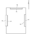
- FIG. It is the schematic sectional drawing which looked at the room of Drawing 1 from the ceiling side.
- It is a schematic perspective view of an example of a reflective polarizer that can be used in a room according to an embodiment of the present invention.
- the expressions “substantially orthogonal” and “substantially orthogonal” include the case where the angle between the two directions is 90 ° ⁇ 10 °, preferably 90 ° ⁇ 7 °, The angle is preferably 90 ° ⁇ 5 °.
- the expressions “substantially parallel” and “substantially parallel” include the case where the angle between two directions is 0 ° ⁇ 10 °, preferably 0 ° ⁇ 7 °, more preferably 0 ° ⁇ 5 °.
- the term “orthogonal” or “parallel” may include a substantially orthogonal state or a substantially parallel state.
- the said angle includes both clockwise rotation and counterclockwise rotation with respect to a reference direction.
- “east”, “west”, “south”, and “north” in the present specification do not mean true orientations with respect to the meridian, but are social conventions regarding housing and housing. It means the upper direction.
- FIG. 1 is a schematic perspective view of a room according to an embodiment of the present invention
- FIG. 2 is a schematic cross-sectional view of the room of FIG. 1 viewed from the ceiling side.
- the illustrated room 100 is defined by a ceiling 10, a floor 20 and a wall 30.
- the wall 30 has a pair of wall surfaces 31 and 32 facing each other and another pair of wall surfaces 33 and 34 facing each other in a direction intersecting the wall surfaces 31 and 32.
- the crossing angle between the wall surfaces 31 and 32 and the wall surfaces 33 and 34 can be set to any appropriate angle as long as human living and living are possible.
- the wall surfaces 31 and 32 and the wall surfaces 33 and 34 are typically substantially orthogonal to each other as illustrated.
- One of the wall surfaces 31, 32, 33, 34 has a window 40.
- the first screen 51 is disposed on the wall surface 32 facing the wall surface 31 having the window 40
- the second screen 52 is disposed on the wall surface 33.
- the wall surface 33 can typically be located on the opposite side of the lowest median direction.
- the window 40 is disposed on the west side
- the first screen 51 is disposed on the east side
- the second screen 52 is disposed on the north side. Either the first screen 51 or the second screen 52 may be omitted depending on the purpose and the direction of the window.
- either the first screen 51 or the second screen 52 is omitted, and only one screen is used to realize a projector projection image with high contrast even in a bright environment.
- the projection can be performed using the first screen 51 and the second screen 52 in accordance with the incident direction of the sun (eg, season, time), even in a bright environment.
- a projector image projected with high contrast can be realized.
- both the first screen 51 (second polarizing plate 62) and the second screen 52 (third polarizing plate 63) are provided for easy understanding will be described. As described above, any one of these may be omitted.
- the first polarizing plate 61 is provided inside the window 40 (inside the room), the second polarizing plate 62 is provided on the projection-side surface of the first screen 51, and the first A third polarizing plate 63 is provided on the projection-side surface of the second screen 52.
- the first polarizing plate, the second polarizing plate, and the third polarizing plate may be collectively referred to simply as a polarizing plate.
- the polarizing plate typically includes a polarizer and a protective film disposed on one side or both sides of the polarizer.
- the first polarizing plate, the second polarizing plate, and the third polarizing plate are typically bonded to the window 40, the first screen 51, and the second screen 52 through an adhesive layer, respectively.
- the absorption axis direction of the polarizer of the first polarizing plate 61, the absorption axis direction of the polarizer of the second polarizing plate 62, and the absorption axis direction of the polarizer of the third polarizing plate 63 are substantially orthogonal or parallel. It is.
- the absorption axis direction of the polarizer of the first polarizing plate 61 can be set to any appropriate direction.
- the absorption axis direction of the polarizer of the first polarizing plate 61 may be a direction substantially parallel to the vertical direction, a direction substantially parallel to the horizontal direction, or the vertical direction or The direction which makes a predetermined angle with respect to a horizontal direction may be sufficient.
- the absorption axis direction of the polarizer of the first polarizing plate 61 is a direction substantially parallel to the vertical direction. Therefore, in this embodiment, the absorption axis direction of the polarizer of the second polarizing plate 62 and the absorption axis direction of the polarizer of the third polarizing plate 63 are substantially parallel to the horizontal direction or the vertical direction, respectively.
- Direction Since such a combination of polarizing plates is one of the features of the embodiment of the present invention, the embodiment of the present invention also includes such a set of polarizing plates.
- the polarizer may be an absorptive polarizer, a reflective polarizer, or may have a laminated structure of an absorptive polarizer and a reflective polarizer.
- the absorption polarizer (hereinafter sometimes simply referred to as a polarizer) is typically a resin film in which a dichroic substance (for example, iodine) is adsorbed and oriented.
- a dichroic substance for example, iodine
- the resin film forming the absorption polarizer may be a single layer resin film or a laminate of two or more layers.
- the absorption polarizer composed of a single-layer resin film include high hydrophilicity such as polyvinyl alcohol (PVA) film, partially formalized PVA film, and ethylene / vinyl acetate copolymer partially saponified film.
- PVA polyvinyl alcohol
- molecular films that have been dyed and stretched with dichroic substances such as iodine and dichroic dyes
- polyene-based oriented films such as PVA dehydrated products and polyvinyl chloride dehydrochlorinated products It is done.
- a polarizer obtained by dyeing a PVA film with iodine and uniaxially stretching is used because of excellent optical properties.
- the dyeing with iodine is performed, for example, by immersing a PVA film in an aqueous iodine solution.
- the stretching ratio of the uniaxial stretching is preferably 3 to 7 times.
- the stretching may be performed after the dyeing treatment or may be performed while dyeing. Moreover, you may dye
- the PVA film is subjected to swelling treatment, crosslinking treatment, washing treatment, drying treatment and the like. For example, by immersing the PVA film in water and washing it before dyeing, not only can the surface of the PVA film be cleaned of dirt and anti-blocking agents, but the PVA film can be swollen to cause uneven staining. Can be prevented.
- the absorption polarizer obtained using the laminate a laminate of a resin substrate and a PVA resin layer (PVA resin film) laminated on the resin substrate, or a resin substrate and Examples thereof include a polarizer obtained by using a laminate with a PVA-based resin layer formed by coating on the resin base material.
- a polarizer obtained by using a laminate of a resin base material and a PVA resin layer applied and formed on the resin base material may be obtained by, for example, applying a PVA resin solution to a resin base material and drying it.
- a PVA-based resin layer is formed thereon to obtain a laminate of a resin base material and a PVA-based resin layer; the laminate is stretched and dyed to make the PVA-based resin layer a polarizer; obtain.
- stretching typically includes immersing the laminate in an aqueous boric acid solution and stretching.
- the stretching may further include, if necessary, stretching the laminate in the air at a high temperature (for example, 95 ° C. or higher) before stretching in the aqueous boric acid solution.
- the obtained resin base material / polarizer laminate may be used as it is (that is, the resin base material may be used as a protective layer of the polarizer), and the resin base material is peeled from the resin base material / polarizer laminate.
- Any appropriate protective layer according to the purpose may be laminated on the release surface. Details of a method for manufacturing such a polarizer are described in, for example, Japanese Patent Application Laid-Open No. 2012-73580. This publication is incorporated herein by reference in its entirety.
- the absorptive polarizer preferably exhibits absorption dichroism at any wavelength between 380 nm and 780 nm.
- the single transmittance of the absorbing polarizer is preferably 42.0% to 46.0%, more preferably 44.5% to 46.0%.
- the polarization degree of the absorbing polarizer is preferably 97.0% or more, more preferably 99.0% or more, and further preferably 99.9% or more.
- the reflective polarizer has a function of transmitting polarized light in a specific polarization state (polarization direction) and reflecting light in other polarization states.
- the reflective polarizer may be a linearly polarized light separation type or a circularly polarized light separation type.
- a linearly polarized light separation type reflective polarizer will be briefly described.
- Examples of the circularly polarized light separation type reflective polarizer include a laminate of a film in which cholesteric liquid crystal is fixed and a ⁇ / 4 plate.
- FIG. 3 is a schematic perspective view of an example of a reflective polarizer.
- the reflective polarizer is a multilayer laminate in which layers A having birefringence and layers B having substantially no birefringence are alternately laminated.
- the total number of layers in such a multilayer stack can be 50-1000.
- the refractive index nx in the x-axis direction of the A layer is larger than the refractive index ny in the y-axis direction, and the refractive index nx in the x-axis direction and the refractive index ny in the y-axis direction of the B layer are substantially the same. is there.
- the difference in refractive index between the A layer and the B layer is large in the x-axis direction and is substantially zero in the y-axis direction.
- the x-axis direction becomes the reflection axis
- the y-axis direction becomes the transmission axis.
- the refractive index difference in the x-axis direction between the A layer and the B layer is preferably 0.2 to 0.3.
- the x-axis direction corresponds to the extending direction of the reflective polarizer in the reflective polarizer manufacturing method.
- the reflective polarizer may include a reflective layer R as the outermost layer as shown in the example of the drawing.
- the A layer is preferably made of a material that develops birefringence by stretching.
- Representative examples of such materials include naphthalene dicarboxylic acid polyesters (for example, polyethylene naphthalate), polycarbonates, and acrylic resins (for example, polymethyl methacrylate). Polyethylene naphthalate is preferred.
- the B layer is preferably made of a material that does not substantially exhibit birefringence even when stretched.
- a typical example of such a material is a copolyester of naphthalenedicarboxylic acid and terephthalic acid.
- the reflective polarizer for example, the one described in JP-T-9-507308 can be used.
- a commercially available product may be used as it is, or a commercially available product may be used after secondary processing (for example, stretching).
- 3M company brand name DBEF and 3M company brand name APF are mentioned, for example.
- any appropriate resin film that can be used as a protective film for a polarizer can be adopted.
- the material used as the main component of the film include cellulose resins such as triacetyl cellulose (TAC), polyester-based, polyvinyl alcohol-based, polycarbonate-based, polyamide-based, polyimide-based, polyethersulfone-based, and polysulfone-based materials.
- transparent resins such as polystyrene, polynorbornene, polyolefin, (meth) acryl, and acetate.
- thermosetting resins such as (meth) acrylic, urethane-based, (meth) acrylurethane-based, epoxy-based, and silicone-based or ultraviolet curable resins are also included.
- a glassy polymer such as a siloxane polymer is also included.
- a polymer film described in JP-A-2001-343529 (WO01 / 37007) can also be used.
- a resin composition containing a thermoplastic resin having a substituted or unsubstituted imide group in the side chain and a thermoplastic resin having a substituted or unsubstituted phenyl group and nitrile group in the side chain for example, a resin composition having an alternating copolymer of isobutene and N-methylmaleimide and an acrylonitrile / styrene copolymer can be mentioned.
- the polymer film can be, for example, an extruded product of the resin composition.
- a protective film is disposed on the surface side of the polarizing plate (on the side opposite to the window in the first polarizing plate, on the side opposite to the screen in the second and third polarizing plates), it is necessary for the viewing side protective film.
- surface treatment such as hard coat treatment, antireflection treatment, sticking prevention treatment, and antiglare treatment may be applied.
- the inner protective film is optically isotropic.
- “optically isotropic” means that the in-plane retardation Re (550) is 0 nm to 10 nm and the thickness direction retardation Rth (550) is ⁇ 10 nm to +10 nm.
- Re ( ⁇ ) is an in-plane retardation measured with light having a wavelength of ⁇ nm at 23 ° C.
- Re (550) is an in-plane retardation measured with light having a wavelength of 550 nm at 23 ° C.
- Rth ( ⁇ ) is a retardation in the thickness direction measured with light having a wavelength of ⁇ nm at 23 ° C.
- Rth (550) is a retardation in the thickness direction measured with light having a wavelength of 550 nm at 23 ° C.
- Nx is the refractive index in the direction in which the in-plane refractive index is maximum (ie, the slow axis direction), and “ny” is the direction orthogonal to the slow axis in the plane (ie, the fast axis direction). “Nz” is the refractive index in the thickness direction.
- each of the first polarizing plate, the second polarizing plate, and the third polarizing plate further includes a retardation layer having an in-plane retardation Re (550) of preferably 100 nm to 200 nm. .
- a circularly polarized light or an elliptically polarized light function can be provided to a 1st polarizing plate, a 2nd polarizing plate, and a 3rd polarizing plate.
- the in-plane retardation Re (550) of the retardation layer is more preferably 120 nm to 180 nm, and still more preferably 130 nm to 160 nm.
- the retardation layer can be typically disposed on the surface side of the polarizing plate (on the side opposite to the window in the first polarizing plate and on the side opposite to the screen in the second and third polarizing plates).
- the retardation layer preferably exhibits a refractive index characteristic of nx> ny ⁇ nz. Therefore, the retardation layer has a slow axis.
- the angle formed between the absorption axis of each polarizer of the first polarizing plate, the second polarizing plate, and the third polarizing plate and the slow axis of the retardation layer is preferably 38 ° to 52 °, and more The angle is preferably 42 ° to 48 °, more preferably about 45 °.
- the retardation layer may exhibit reverse dispersion wavelength characteristics in which the retardation value increases with the wavelength of the measurement light, or may exhibit positive wavelength dispersion characteristics in which the retardation value decreases with the wavelength of the measurement light.
- the phase difference value may exhibit a flat chromatic dispersion characteristic that hardly changes depending on the wavelength of the measurement light.
- Re (450) / Re (550) is preferably 0.85 or more and less than 1.00, more preferably 0.95 or more and less than 1.00
- Re (550) / Re (650) is preferably 0.90 or more and less than 1.00, and more preferably 0.95 or more and less than 1.00.
- Re (450) / Re (550) is preferably 1.00 to 1.15, more preferably 1.00 to 1.
- Re (550) / Re (650) is preferably 1.00 to 1.10, more preferably 1.00 to 1.05.
- the thickness of the retardation layer can be set so as to obtain the desired in-plane retardation.
- the thickness of the retardation layer is preferably 20 ⁇ m to 100 ⁇ m, more preferably 30 ⁇ m to 70 ⁇ m.
- the retardation layer may be composed of any appropriate resin film that can realize the above characteristics.
- the resin forming the retardation layer include polyarylate, polyamide, polyimide, polyester, polyaryletherketone, polyamideimide, polyesterimide, polyvinyl alcohol, polyfumaric acid ester, polyethersulfone, polysulfone, norbornene resin, and polycarbonate. Resins, cellulose resins and polyurethanes can be mentioned. These resins may be used alone or in combination.
- the retardation layer can be obtained by stretching a film formed from these resins under conditions according to the type of resin and the desired characteristics.
- the room according to the embodiment of the present invention can clearly display the image projected by the projector even in a bright environment, it can be suitably used as an image projection space of the projector.
- the projection image by the projector can be clearly displayed even in a bright environment by appropriately designing the projector projection space instead of improving the configuration of the projector itself ( (Typically with high contrast).
- the room according to the embodiment of the present invention can clearly display the projection image by the projector even in a bright environment, the application is expected to expand.
Landscapes
- Engineering & Computer Science (AREA)
- Physics & Mathematics (AREA)
- Architecture (AREA)
- General Physics & Mathematics (AREA)
- Structural Engineering (AREA)
- Optics & Photonics (AREA)
- Civil Engineering (AREA)
- Multimedia (AREA)
- Polarising Elements (AREA)
- Overhead Projectors And Projection Screens (AREA)
- Projection Apparatus (AREA)
- Transforming Electric Information Into Light Information (AREA)
Abstract
L'invention concerne une pièce qui peut réaliser une image projetée par projecteur ayant un contraste élevé même dans un environnement lumineux. Une pièce conforme à la présente invention est délimitée par : un plafond ; un plancher ; une paire de surfaces faisant office de murs et étant opposées l'une à l'autre ; et une autre paire de surfaces faisant office de murs et étant opposées l'une à l'autre dans la direction croisant la paire de surfaces faisant office de murs. Parmi la paire de surfaces faisant office de murs et l'autre paire de surfaces faisant office de murs, l'une des paires de surfaces faisant office de murs est munie d'une fenêtre, un premier écran est disposé sur la surface faisant office de mur qui est opposée à la surface faisant office de mur possédant la fenêtre, et/ou un second écran est disposé sur la surface faisant office de mur qui se trouve du côté opposé dans la direction d'aboutissement inférieure. Des plaques de polarisation sont disposées à l'intérieur de la fenêtre, du côté de la surface de projection du premier écran, et/ou du côté de la surface de projection du second écran. L'axe d'absorption d'un polariseur de la plaque de polarisation située dans la fenêtre est orienté de façon à être sensiblement perpendiculaire ou parallèle à l'axe d'absorption d'un polariseur de la plaque de polarisation située dans le premier écran et/ou à l'axe d'absorption d'un polariseur de la plaque de polarisation située dans le second écran.
Priority Applications (5)
| Application Number | Priority Date | Filing Date | Title |
|---|---|---|---|
| US17/047,801 US11550212B2 (en) | 2018-04-16 | 2019-04-03 | Room |
| JP2020514068A JPWO2019202988A1 (ja) | 2018-04-16 | 2019-04-03 | 部屋 |
| EP19789077.5A EP3783433A4 (fr) | 2019-04-03 | Pièce | |
| CN201980026500.3A CN111989617A (zh) | 2018-04-16 | 2019-04-03 | 房间 |
| JP2023000434A JP2023058484A (ja) | 2018-04-16 | 2023-01-05 | 部屋 |
Applications Claiming Priority (2)
| Application Number | Priority Date | Filing Date | Title |
|---|---|---|---|
| JP2018-078449 | 2018-04-16 | ||
| JP2018078449 | 2018-04-16 |
Publications (1)
| Publication Number | Publication Date |
|---|---|
| WO2019202988A1 true WO2019202988A1 (fr) | 2019-10-24 |
Family
ID=68239508
Family Applications (1)
| Application Number | Title | Priority Date | Filing Date |
|---|---|---|---|
| PCT/JP2019/014783 Ceased WO2019202988A1 (fr) | 2018-04-16 | 2019-04-03 | Pièce |
Country Status (4)
| Country | Link |
|---|---|
| US (1) | US11550212B2 (fr) |
| JP (2) | JPWO2019202988A1 (fr) |
| CN (1) | CN111989617A (fr) |
| WO (1) | WO2019202988A1 (fr) |
Cited By (2)
| Publication number | Priority date | Publication date | Assignee | Title |
|---|---|---|---|---|
| JPWO2022091806A1 (fr) * | 2020-10-29 | 2022-05-05 | ||
| WO2022163221A1 (fr) * | 2021-01-29 | 2022-08-04 | 日東電工株式会社 | Cloison polarisée, ensemble cloison polarisée et espace cloisonné les utilisant |
Citations (18)
| Publication number | Priority date | Publication date | Assignee | Title |
|---|---|---|---|---|
| JPS6364483A (ja) * | 1986-09-05 | 1988-03-22 | Kawasaki Heavy Ind Ltd | 室内画像投影方法 |
| JPH01191824A (ja) * | 1988-01-28 | 1989-08-01 | Kawasaki Heavy Ind Ltd | 電子表示器用照明室 |
| JPH05134214A (ja) * | 1991-11-14 | 1993-05-28 | Sony Corp | 映像投影システム |
| JPH05204046A (ja) * | 1992-01-28 | 1993-08-13 | Jamco Corp | 画像投影装置 |
| JPH0675303A (ja) * | 1992-08-26 | 1994-03-18 | Toppan Printing Co Ltd | 再帰反射性を有する反射型スクリーン |
| JPH06167745A (ja) * | 1992-11-27 | 1994-06-14 | Mitsui Toatsu Chem Inc | 反射型プロジェクター |
| JPH09106008A (ja) * | 1995-10-13 | 1997-04-22 | Matsushita Electric Ind Co Ltd | 投写装置 |
| JPH09507308A (ja) | 1993-12-21 | 1997-07-22 | ミネソタ マイニング アンド マニュファクチャリング カンパニー | 光学偏光装置 |
| JPH09211733A (ja) * | 1996-02-05 | 1997-08-15 | Nec Corp | 偏光スクリーンを備えた室内構造 |
| WO2001037007A1 (fr) | 1999-11-12 | 2001-05-25 | Kaneka Corporation | Film transparent |
| JP2001346219A (ja) | 2000-05-31 | 2001-12-14 | Fujitsu General Ltd | プロジェクション方法及びプロジェクタ装置 |
| JP2001343529A (ja) | 2000-03-30 | 2001-12-14 | Kanegafuchi Chem Ind Co Ltd | 偏光子保護フィルムおよびその製造方法 |
| JP2003186106A (ja) * | 2001-12-17 | 2003-07-03 | Mitsubishi Electric Corp | プロジェクションシステム |
| JP2012023494A (ja) | 2010-07-13 | 2012-02-02 | Seiko Epson Corp | 画像処理装置、画像表示装置、及び画像処理方法 |
| JP2012073580A (ja) | 2010-09-03 | 2012-04-12 | Nitto Denko Corp | 薄型偏光膜の製造方法 |
| JP2013109183A (ja) | 2011-11-22 | 2013-06-06 | Canon Inc | 投射型表示装置 |
| JP2017015897A (ja) * | 2015-06-30 | 2017-01-19 | 日本ゼオン株式会社 | 画像投射システム及び投影面部材 |
| JP2017111432A (ja) * | 2015-12-10 | 2017-06-22 | 日東電工株式会社 | 円偏光板およびそれを用いたフレキシブルな画像表示装置 |
Family Cites Families (6)
| Publication number | Priority date | Publication date | Assignee | Title |
|---|---|---|---|---|
| JPH06130223A (ja) * | 1992-10-14 | 1994-05-13 | Kuraray Co Ltd | 偏光フィルタ |
| KR0142032B1 (ko) * | 1993-09-24 | 1998-07-01 | 마쓰오 히로또 | 편광 스크린 |
| WO2011062822A1 (fr) * | 2009-11-17 | 2011-05-26 | 3M Innovative Properties Company | Écran de projection frontale sensible à la polarisation |
| US8982459B1 (en) * | 2012-06-20 | 2015-03-17 | Rawles Llc | Passive projection screen for presenting projected images in 3D |
| US9044863B2 (en) * | 2013-02-06 | 2015-06-02 | Steelcase Inc. | Polarized enhanced confidentiality in mobile camera applications |
| WO2016014560A2 (fr) | 2014-07-22 | 2016-01-28 | Barco,Inc. | Systèmes et procédés d'affichage employant des écrans réfléchissants polarisants |
-
2019
- 2019-04-03 WO PCT/JP2019/014783 patent/WO2019202988A1/fr not_active Ceased
- 2019-04-03 CN CN201980026500.3A patent/CN111989617A/zh active Pending
- 2019-04-03 US US17/047,801 patent/US11550212B2/en active Active
- 2019-04-03 JP JP2020514068A patent/JPWO2019202988A1/ja active Pending
-
2023
- 2023-01-05 JP JP2023000434A patent/JP2023058484A/ja active Pending
Patent Citations (18)
| Publication number | Priority date | Publication date | Assignee | Title |
|---|---|---|---|---|
| JPS6364483A (ja) * | 1986-09-05 | 1988-03-22 | Kawasaki Heavy Ind Ltd | 室内画像投影方法 |
| JPH01191824A (ja) * | 1988-01-28 | 1989-08-01 | Kawasaki Heavy Ind Ltd | 電子表示器用照明室 |
| JPH05134214A (ja) * | 1991-11-14 | 1993-05-28 | Sony Corp | 映像投影システム |
| JPH05204046A (ja) * | 1992-01-28 | 1993-08-13 | Jamco Corp | 画像投影装置 |
| JPH0675303A (ja) * | 1992-08-26 | 1994-03-18 | Toppan Printing Co Ltd | 再帰反射性を有する反射型スクリーン |
| JPH06167745A (ja) * | 1992-11-27 | 1994-06-14 | Mitsui Toatsu Chem Inc | 反射型プロジェクター |
| JPH09507308A (ja) | 1993-12-21 | 1997-07-22 | ミネソタ マイニング アンド マニュファクチャリング カンパニー | 光学偏光装置 |
| JPH09106008A (ja) * | 1995-10-13 | 1997-04-22 | Matsushita Electric Ind Co Ltd | 投写装置 |
| JPH09211733A (ja) * | 1996-02-05 | 1997-08-15 | Nec Corp | 偏光スクリーンを備えた室内構造 |
| WO2001037007A1 (fr) | 1999-11-12 | 2001-05-25 | Kaneka Corporation | Film transparent |
| JP2001343529A (ja) | 2000-03-30 | 2001-12-14 | Kanegafuchi Chem Ind Co Ltd | 偏光子保護フィルムおよびその製造方法 |
| JP2001346219A (ja) | 2000-05-31 | 2001-12-14 | Fujitsu General Ltd | プロジェクション方法及びプロジェクタ装置 |
| JP2003186106A (ja) * | 2001-12-17 | 2003-07-03 | Mitsubishi Electric Corp | プロジェクションシステム |
| JP2012023494A (ja) | 2010-07-13 | 2012-02-02 | Seiko Epson Corp | 画像処理装置、画像表示装置、及び画像処理方法 |
| JP2012073580A (ja) | 2010-09-03 | 2012-04-12 | Nitto Denko Corp | 薄型偏光膜の製造方法 |
| JP2013109183A (ja) | 2011-11-22 | 2013-06-06 | Canon Inc | 投射型表示装置 |
| JP2017015897A (ja) * | 2015-06-30 | 2017-01-19 | 日本ゼオン株式会社 | 画像投射システム及び投影面部材 |
| JP2017111432A (ja) * | 2015-12-10 | 2017-06-22 | 日東電工株式会社 | 円偏光板およびそれを用いたフレキシブルな画像表示装置 |
Cited By (6)
| Publication number | Priority date | Publication date | Assignee | Title |
|---|---|---|---|---|
| JPWO2022091806A1 (fr) * | 2020-10-29 | 2022-05-05 | ||
| WO2022091806A1 (fr) * | 2020-10-29 | 2022-05-05 | 日東電工株式会社 | Film de tableau blanc, tableau blanc, système de prévention de peep |
| JP7470206B2 (ja) | 2020-10-29 | 2024-04-17 | 日東電工株式会社 | ホワイトボードフィルム、ホワイトボードおよび覗き見防止システム |
| US12455500B2 (en) | 2020-10-29 | 2025-10-28 | Nitto Denko Corporation | Whiteboard film, whiteboard, peep prevention system |
| WO2022163221A1 (fr) * | 2021-01-29 | 2022-08-04 | 日東電工株式会社 | Cloison polarisée, ensemble cloison polarisée et espace cloisonné les utilisant |
| JPWO2022163221A1 (fr) * | 2021-01-29 | 2022-08-04 |
Also Published As
| Publication number | Publication date |
|---|---|
| CN111989617A (zh) | 2020-11-24 |
| JPWO2019202988A1 (ja) | 2021-05-20 |
| US20210141300A1 (en) | 2021-05-13 |
| JP2023058484A (ja) | 2023-04-25 |
| US11550212B2 (en) | 2023-01-10 |
| EP3783433A1 (fr) | 2021-02-24 |
Similar Documents
| Publication | Publication Date | Title |
|---|---|---|
| JP4689769B1 (ja) | 液晶表示装置 | |
| JP6139572B2 (ja) | 光学フィルム | |
| KR102783790B1 (ko) | 화상 표시 장치 및 상기 화상 표시 장치에 사용되는 원편광판 | |
| JP6690907B2 (ja) | 光学積層体、複合偏光板及び液晶表示装置 | |
| TW200837405A (en) | Display including reflective polarizer | |
| JP6274446B2 (ja) | 長尺光学フィルム積層体、長尺光学フィルム積層体のロール及びips液晶表示装置 | |
| WO2004036273A1 (fr) | Film optique et écran à affichage à cristaux liquides | |
| WO2003091792A1 (fr) | Unite d'affichage a cristaux liquides a agrandissement de l'angle de vue | |
| WO2015050075A1 (fr) | Ensemble de plaques polarisantes et panneau d'affichage à cristaux liquides à plaque avant intégrée | |
| WO2017221405A1 (fr) | Corps stratifié de film optique long, rouleau de corps stratifié de film optique long et dispositif d'affichage à cristaux liquides à commutation dans le plan (cdp) | |
| CN111712739A (zh) | 光学层积体、显示面板和显示装置 | |
| JP2023057094A (ja) | 偏光板のセットおよび該セットを含む画像表示装置 | |
| JP2005345958A (ja) | 液晶パネル、偏光板および液晶表示装置 | |
| JP2023058484A (ja) | 部屋 | |
| JP2005309386A (ja) | Ipsモード液晶表示装置 | |
| JP2005017466A (ja) | 光学素子、集光バックライトシステムおよび液晶表示装置 | |
| WO2010001920A1 (fr) | Dispositif d'affichage à cristaux liquides | |
| JP2005345990A (ja) | 液晶パネル、偏光板および液晶表示装置 | |
| WO2019202987A1 (fr) | Film de prévention d'éblouissement de vitre | |
| WO2022163221A1 (fr) | Cloison polarisée, ensemble cloison polarisée et espace cloisonné les utilisant | |
| JP2008139806A (ja) | 積層光学フィルム、積層光学フィルムを用いた液晶パネルおよび液晶表示装置 | |
| JP4761395B2 (ja) | 積層光学フィルム、積層光学フィルムを用いた液晶パネルおよび液晶表示装置 | |
| JP2021170130A (ja) | 位相差層付偏光板および有機el表示装置 | |
| TW202131031A (zh) | 相位差板,以及具有該相位差板之圓偏光板、液晶顯示裝置及有機el顯示裝置 | |
| JP4911603B2 (ja) | 液晶パネルおよび液晶表示装置 |
Legal Events
| Date | Code | Title | Description |
|---|---|---|---|
| 121 | Ep: the epo has been informed by wipo that ep was designated in this application |
Ref document number: 19789077 Country of ref document: EP Kind code of ref document: A1 |
|
| ENP | Entry into the national phase |
Ref document number: 2020514068 Country of ref document: JP Kind code of ref document: A |
|
| NENP | Non-entry into the national phase |
Ref country code: DE |
|
| ENP | Entry into the national phase |
Ref document number: 2019789077 Country of ref document: EP Effective date: 20201116 |