WO2019239571A1 - Dispositif de coupe de porte et matrice de moulage - Google Patents
Dispositif de coupe de porte et matrice de moulage Download PDFInfo
- Publication number
- WO2019239571A1 WO2019239571A1 PCT/JP2018/022848 JP2018022848W WO2019239571A1 WO 2019239571 A1 WO2019239571 A1 WO 2019239571A1 JP 2018022848 W JP2018022848 W JP 2018022848W WO 2019239571 A1 WO2019239571 A1 WO 2019239571A1
- Authority
- WO
- WIPO (PCT)
- Prior art keywords
- mold
- fixed
- gate
- movable
- cutting device
- Prior art date
- Legal status (The legal status is an assumption and is not a legal conclusion. Google has not performed a legal analysis and makes no representation as to the accuracy of the status listed.)
- Ceased
Links
Images











Classifications
-
- B—PERFORMING OPERATIONS; TRANSPORTING
- B29—WORKING OF PLASTICS; WORKING OF SUBSTANCES IN A PLASTIC STATE IN GENERAL
- B29C—SHAPING OR JOINING OF PLASTICS; SHAPING OF MATERIAL IN A PLASTIC STATE, NOT OTHERWISE PROVIDED FOR; AFTER-TREATMENT OF THE SHAPED PRODUCTS, e.g. REPAIRING
- B29C45/00—Injection moulding, i.e. forcing the required volume of moulding material through a nozzle into a closed mould; Apparatus therefor
- B29C45/17—Component parts, details or accessories; Auxiliary operations
- B29C45/38—Cutting-off equipment for sprues or ingates
Definitions
- the present invention relates to a gate cutting device and a molding die capable of cutting a gate in a mold.
- a blade core that cuts the gate is provided on a slide core that slides in conjunction with the operation of opening the mold clamping die, and the blade is made to slide by sliding the slide core in conjunction with the operation of mold opening. Cut the gate at the part.
- a side gate having a runner part and a gate part is provided on the slide core, a gate cutting part is provided at the tip of the gate part, a hydraulic cylinder is attached to the slide core, and the mold is closed. Slide the slide core to cut the gate.
- the injection mold described in Patent Document 2 has an advantage that the gate can be reliably cut because the molded product does not move when the gate is cut because the gate is cut in a closed state.
- the injection mold runner described in Patent Document 1 and Patent Document 2 is a cold runner, but in the injection mold, a hot runner is also used in addition to the cold runner. Therefore, it is desirable that the gate cutting device is compatible with not only a cold runner but also a hot runner.
- An object of the present invention is to provide a compact gate cutting device that can be easily incorporated into a molding die, a compact and easy to incorporate into a molding die, and applicable to a hot runner, and the gate. It is providing the metal mold
- the present invention is a gate cutting device incorporated in a molding die for molding a molded product with a fixed mold and a movable mold, and is slidably engaged with a slide cutter for cutting the gate, and the slide cutter, A holding piece that slides the slide cutter, and a holder that is fixed to or integrally formed with the fixed mold or the movable mold, and that accommodates the holding piece so as to be able to advance and retreat, and the holder includes the gate.
- the slide cutter is slid by the movement of the holding piece, and the gate is cut by the gate portion. It is a door cutting device.
- the slide cutter, the holding piece, and the holder are unitized and incorporated into the molding die.
- the gate is cut in a state where at least a part of the parting surface is closed.
- the slide cutter continues to slide even after the gate is cut, and the tip of the resin remaining on the runner is pushed or pulled by the wall surface of the gate portion, so that at least one of the resin remaining on the runner The part is separated from the runner.
- the gate portion is tapered from the runner side toward the cavity side.
- the fixed mold includes a fixed-side mounting plate and a fixed-side mold plate that can be detached from the fixed-side mounting plate in a mold opening direction
- the holder includes the fixed-side mold plate.
- the holding piece is fixed to the fixed-side mounting plate
- the fixed-side mold plate is fixed to the fixed-side mounting plate in a state where the fixed die and the movable die are closed.
- the slide cutter is capable of cutting the gate while the fixed mold and the movable mold are closed.
- the fixed mold includes a fixed mold and a fixed insert that can be detached from the fixed mold in the mold opening direction, and the holder is fixed to the fixed insert.
- the holding piece is fixed to the fixed-side mold plate, and the fixed-side nesting is separated from the fixed-side mold plate as the fixed mold and the movable mold are opened.
- the slide cutter is characterized in that the gate can be cut in a state where at least a part of the parting surface is closed.
- the movable mold includes a movable mold plate and a movable receiving plate that can be detached from the movable mold plate in the mold opening direction, and the holder includes the movable mold plate.
- the holding piece is fixed to the movable side receiving plate, and the movable side receiving plate is closed when the fixed type and the movable type are closed.
- the slide cutter is capable of cutting the gate while the fixed mold and the movable mold are closed.
- the movable mold includes a movable mold plate, a movable nest fixed to the movable mold plate, and a movable receiving plate detachable from the movable mold plate in the mold opening direction.
- the holder is sandwiched between the movable side mold plate and the movable side insert, the holding piece is fixed to the movable side receiving plate, and the movable side receiving plate is fixed to the fixed mold and the
- the movable die can be moved away from the movable side mold plate in a closed state, and the slide cutter can cut the gate in a state in which the fixed die and the movable die are closed.
- the slide cutter slides inward of the molded product when the gate is cut.
- the holder is fixed to or integrally formed with the fixed mold, and the holding piece is separated from the fixed mold as the fixed mold and the movable mold are opened.
- the slide cutter is characterized in that the gate can be cut before the molded product protrudes.
- the present invention is a molding die including a fixed die, a movable die, and the gate cutting device.
- the present invention is a molded product molded with the molding die.
- a gate cutting device that is compact and easy to incorporate into a molding die
- a gate cutting device that is compact and easy to incorporate into a molding die, and can be applied to a hot runner, and the gate A molding die provided with a cutting device can be provided.
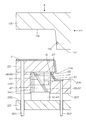
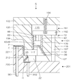
- FIG. It is principal part sectional drawing at the time of the gate cutting
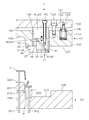
- FIG. 1A is a cross-sectional view of the main part of the injection mold 1 according to the first embodiment of the present invention in a closed state
- FIG. 1B is a plan view for explaining the configuration of the gate cutting device 11.
- . 2, 3, and 4 are cross-sectional views of main parts when the gate of the injection mold 1 according to the first embodiment of the present invention is cut, when the mold opening is completed, and when the molded product P is pushed up.
- 1 (A) and FIGS. 2 to 4 are views seen from the front.
- the direction is the fixed mold 101 side in FIG. 1 and the movable mold 201 side is down.
- the molded product P side in FIG. are the same in other embodiments.
- dots are attached to the molded product P for easy understanding. This point is the same in other embodiments.
- the injection mold 1 includes a fixed mold 101 that molds a molded product P, a movable mold 201, and a gate cutting device 11 that cuts a gate.
- the fixed mold 101 includes a fixed-side mounting plate 102 and a fixed-side mold plate 105 that can be attached to and detached from the fixed-side mounting plate 102.
- the fixed mold 101 is provided with fixed-side mold plate driving means 121 for detaching the fixed-side mold plate 105 from the fixed-side mounting plate 102.
- the fixed-side template 105 has a cavity surface 108 that forms the outer surface of the molded product P, and further has an accommodating portion 109 that accommodates the gate cutting device 11 near the cavity surface 108.
- the accommodating portion 109 is provided so as to penetrate the fixed side template 105 in the vertical direction.
- the fixed-side template driving means 121 is a means for moving the fixed-side template 105 away from the fixed-side mounting plate 102, and a spring 122 attached to the fixed-side template 105, and the fixed-side mounting plate 102 and the fixed-side template 102 are fixed.
- a stop bolt 123 that regulates the separation distance from the side mold plate 105 is provided.
- the spring 122 is accommodated in a recess 110 provided so as to communicate with the upper surface 106 of the fixed-side template 105.
- a guide pin 124 that guides the expansion and contraction of the spring 122 is attached to the bottom surface 103 of the fixed-side attachment plate 102.
- the movable mold 201 includes a movable mold plate 205 and a movable insert 221 fixed to the movable mold plate 205.
- a core surface 223 that forms the inner surface of the molded product P is provided on the outer periphery of the movable side insert 221.
- the movable side template 205 is provided with an accommodating portion 209 into which the slide cutter 15 of the gate cutting device 11 and the lower portion of the holder 61 are fitted on the upper surface 206.
- the housing portion 209 is a substantially rectangular recess when viewed from the front (see FIG. 3), and the bottom surface 210 of the housing portion 209 is provided in parallel with the top surface 206 of the movable side template 205.
- a concave portion 211 serving as the runner R is provided (see FIG. 4).
- a concave portion 212 into which the tip end portion 25 of the cutter 21 is fitted is provided at the upper left end of the housing portion 209 (see FIG. 3).
- the movable side insert 221 and the movable side mold plate 205 have insertion holes through which the ejector pins 301 for pushing out (projecting) the molded product P are inserted, and the movable side mold plate 205 has a runner R after gate cutting.
- An insertion hole is provided through which the ejector pin 302 for extruding (extruding) the remaining resin is inserted.
- the gate cutting device 11 is a device that cuts the gate G connected to the molded product P.
- the slide cutter 15 that cuts the gate G, and the holding piece 41 that slidably engages the slide cutter 15 and slides the slide cutter 15.
- a holder 61 for accommodating the holding piece 41 so as to be able to advance and retreat.
- the slide cutter 15 includes a cutter 21 that cuts the gate G and a sliding piece 31 that supports the cutter 21.
- the cutter 21 includes a cubic main body 22 and a distal end 25 provided so as to protrude from the main body 22, and the main body base end 24 is fixed to the sliding piece 31.
- the distal end portion 25 is smaller than the main body portion 22 and is connected to the main body portion 22.
- the cutter 21 and the sliding piece 31 are separately manufactured and joined, but the cutter 21 and the sliding piece 31 may be integrally formed.
- a gate portion 26 serving as a gate G is provided at a connecting portion between the main body portion 22 and the tip portion 25 of the cutter 21.
- the gate portion 26 is a through hole, and the tip end side connected to the cavity C is smaller than the base end side connected to the runner R, and has a tapered shape (see the enlarged view of FIG. 3A). Further, the gate portion 26 has an inclined surface 27 on the main body portion 22 side and a vertical surface 28 on the tip portion 25 side (left side), and a blade is provided at the tip of the vertical surface 28 on the cavity C side.
- the sliding piece 31 is slidably connected to the holding piece 41, moves with the movement of the holding piece 41, and moves the attached cutter 21 forward and backward.
- the sliding piece 31 has a trapezoidal shape in which the right side surface of the rectangular block member is cut obliquely and the upper part is smaller than the lower part (see FIG. 1).
- the cutter 21 has a main body base end 24 fixed to the left side surface 34 of the sliding piece 31 so that the main body bottom face 23 and the bottom face 33 of the sliding piece 31 are flush with each other.
- the sliding piece 31 is provided with a dovetail groove 36 in which a ridge 52 provided on the inclined surface of the holding piece 41 is slidably fitted on the right side surface 35 which is an inclined surface. Further, the front outer wall 37 and the rear outer wall of the sliding piece 31 are provided with ridges 38 that are slidably fitted into the concave grooves 68 provided in the holder 61.
- the holding piece 41 is slidably engaged with the sliding piece 31 and moves back and forth in the vertical direction to slide the slide cutter 15 in the horizontal direction.
- the holding piece 41 includes a rectangular block-shaped base 45 and a piece member 47 slidably engaged with the sliding piece 31.
- the piece member 47 is joined to the bottom surface of the base 45, and the base 45 and the piece member 47 are integrated.
- the base 45 and the piece member 47 are separately manufactured and joined, but the base 45 and the piece member 47 may be integrally formed.
- the piece member 47 has a trapezoidal shape in which the left side surface of the rectangular block member is cut obliquely and the lower surface is narrower than the upper surface in a front view of FIG.
- the piece member 47 is provided with a ridge 52 slidably fitted into a dovetail groove 36 provided on the inclined surface of the holding piece 31 on the left side surface 50 which is an inclined surface.
- the front outer wall 51 and the rear outer wall of the piece member 47 are provided with ridges 53 that are slidably fitted into the concave grooves 69 that are holding piece guides provided on the holder 61.
- the holding piece 41 is fixed to the fixed side mounting plate 102 by the mounting bolt 55 so that the upper surface of the base 45 is in contact with the bottom surface 103 of the fixed side mounting plate 102.
- the holder 61 accommodates the holding piece 41 so as to be able to advance and retreat, guides the holding piece 41 in the vertical direction, and guides the slide cutter 15 in the cutting direction of the gate G.
- the holder 61 has a U-shaped cross section (see FIG. 1 (B)), is formed in a box shape having an internal space whose upper end surface and lower end surface are open, and the lower wall of the left wall surface 65 has an entrance / exit of the cutter 21. 66 is provided.
- the holder 61 is attached to the accommodating portion 109 so that the upper end 67 of the entrance / exit is flush with the bottom surface 107 of the fixed-side template 105. Therefore, the entrance / exit 66 of the cutter 21 provided in the holder 61 protrudes downward from the bottom surface 107 of the fixed-side template 105.
- the portion of the holder 61 that protrudes downward from the bottom surface 107 of the fixed side template 105 is configured to be accommodated in the accommodating portion 209 of the movable side template 205 when the mold is closed.
- the holder 61 has a ridge of the sliding piece 31 that guides the sliding piece 31 of the slide cutter 15 in the left-right direction on the inner wall 71 (not shown) on the near side and the inner wall 71 on the back side when FIG.
- a concave groove 68 into which 38 is fitted is formed in the horizontal direction, and a concave groove 69 into which the ridge 53 of the holding piece 41 for guiding the holding piece 41 in the vertical direction is provided in the vertical direction.
- the slide cutter 15 is slidably engaged with the holding piece 41, and is incorporated into the holder 61 in a state where the cutter 21 protrudes from the entrance 66 of the holder 61. At this time, the cutter 21 abuts the upper surface 29 of the main body portion 22 and the tip portion 25 slidably on the bottom surface 107 of the fixed side template 105. In the mold closed state, the lower end 75 of the holder 61, the bottom surface 23 of the main body portion of the cutter 21, and the bottom surface 33 of the sliding piece abut against the bottom surface 210 of the housing portion 209 provided on the movable side mold plate 205.
- the cutter 21 In the mold closed state, the cutter 21 has moved to the leftmost side (see FIG. 1), and the tip 25 of the cutter 21 fits into the recess 212. As a result, the upper surface of the concave portion 211 is closed, and an L-shaped space portion is formed on the left side of the accommodating portion 209 in a front view.
- This space portion is the runner R, and a sprue (not shown) is connected to the base end, the tip is a gate G, and the gate G is connected to the cavity C (see FIG. 4).
- the state where the mold is closed means the state of FIG. 1 in which the fixed mold 101 and the movable mold 201 are in contact with each other and the parting surface is closed.
- the parting surfaces are the bottom surface 107 of the fixed-side template 105 and the top surface 206 of the movable-side template 205.
- the fixed side mounting plate 102 and the fixed side mold plate 105 are in contact with each other, and the spring 122 of the fixed side mold plate driving means 121 is in a compressed state.
- the molded product P is taken out through the pressure holding and cooling process, but the mold opening is performed as follows.
- the fixed-side template 105 is retracted via the fixed-side template driving means 121 with the parting surface closed.
- the retraction of the fixed-side template 105 means that the fixed-side template 105 moves away from the fixed-side mounting plate 102 and moves downward in FIG.
- the fixed-side mold plate 105 and the movable mold 201 are moved backward integrally (see FIG. 2).
- the holder 61 When the stationary side template 105 is retracted, the holder 61 is also lowered, so that the holding piece 41 is raised relative to the holder 61. As a result, the sliding piece 31 that engages with the holding piece 41 is guided by the concave portion 68 that is the sliding piece guide of the holder 61 and horizontally moves to the right. Accordingly, the cutter 21 also slides to the right while being sandwiched between the bottom surface 107 of the fixed-side template 105 and the bottom surface 210 of the housing portion.
- ⁇ Slide cutter 15 slides to the right, so that gate section 26 crosses gate G and cuts gate G.
- the gate portion 26 is provided with a blade, and the gate portion 26 has a smaller tapered shape on the cavity C side than the runner R side, so the gate G has a small area and the slide cutter 15 slides slightly to the right. Only the gate G is easily cut off.
- the gate G is cut at an initial stage when the fixed-side template 105 starts to retract.
- the resin of the runner R does not change from the state before the gate G is cut.
- the stationary-side template 105 continues to retract until it is prevented from moving by the stop bolt 123.
- the slide cutter 15 slides to the right with the vertical surface 28 of the gate portion 26 of the cutter 21 hooked to the tip of the resin of the runner R from which the gate G has been cut. Since the portion is pulled to the right side, a part of the resin is detached from the runner R (see FIG. 2).
- the process proceeds to the second step.
- the movable mold 201 is retracted from the fixed mold 101 and the parting surface is opened (see FIG. 3).
- the resin of the molded product P and the runner R is ejected by the ejector pins 301 and 302 (see FIG. 4). As a result, the resin of the molded product P and the runner R from which the gate G has been cut is recovered.
- the gate cutting device 11 is compact and unitized, it can be easily incorporated into the injection mold 1 and the injection mold 1 including the gate cutting device 11 can be manufactured in a compact and inexpensive manner. Further, in the injection mold 1 of the first embodiment, the gate G is cut in the closed state, so that the gate G can be cut reliably and cleanly.
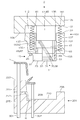
- FIG. 5 is a cross-sectional view of the main part of the injection mold 2 according to the second embodiment of the present invention in a closed state.
- 6, 7, and 8 are cross-sectional views of main parts after the gate cutting of the injection mold 2 according to the second embodiment of the present invention, when the mold opening is completed, and when the molded product P is pushed up.
- the same components as those of the injection mold 1 of the first embodiment shown in FIGS. 1 to 4 are denoted by the same reference numerals and description thereof is omitted.
- An injection mold 2 according to the second embodiment includes a fixed mold 101 that molds a molded product P, a movable mold 201, and a gate cutting device 11 that cuts a gate.
- the injection mold 1 according to the first embodiment Although the basic configuration is the same, the installation procedure and operation procedure of the gate cutting device 11 are different.
- the fixed mold 101 includes a fixed-side mounting plate (not shown), a fixed-side mold plate 105, and a fixed-side insert 131 that is detachably attached to the fixed-side mold plate 105 via a spring 141. Both the fixed-side template 105 and the fixed-side insert 131 have cavity surfaces 108 and 135 that form the outer surface of the molded product P.
- the fixed-side insert 131 is attached to the recessed portion 112 in which the fixed-side mold plate 105 is partially cut out, and the fixed-side insert top surface 132 is fixed to the bottom-side 107 of the fixed-side mold plate 105 when the mold is closed.
- a bottom surface 133 of 131 abuts on an upper surface 206 of the movable side template 205.
- the fixed side nest 131 includes a spring accommodating groove 137 that accommodates a spring 141 that moves the fixed side nest 131 away from the fixed side template 105.
- the spring 141 has an upper end fixed to the bottom surface 107 of the fixed-side template 105 and a lower end fixed to the bottom surface of the spring accommodating groove 137, and the fixed-side insert 131 is connected to the fixed-side template 105 via the spring 141.
- the spring 141 is in a compressed state when the mold is closed (see FIG. 5), and is a fixed-side nesting driving means that moves the fixed-side nesting 131 away from the fixed-side mold plate 105 as the mold opens.
- the fixed-side insert 131 and the fixed-side template 105 are provided with stop bolts (not shown) that restrict the mutual separation distance as the stop bolt 123 of the first embodiment.
- the fixed-side insert 131 has an accommodating portion 138 that accommodates the gate cutting device 11 near the cavity surface 135.
- the accommodating portion 138 is provided so as to penetrate the fixed side insert 131 in the vertical direction.
- the holder 61 is attached to the accommodating portion 138 of the fixed side insert 131 so that the upper end 67 of the entrance / exit of the cutter 21 is flush with the bottom surface 133 of the fixed side insert 131. Therefore, the entrance / exit 66 of the cutter 21 provided in the holder 61 protrudes downward from the bottom surface 133 of the fixed side insert 131.
- a portion of the holder 61 that protrudes downward from the bottom surface 133 of the fixed side insert 131 is configured to be housed in the housing portion 209 of the movable side mold plate 205 when the mold is closed.
- the base 45 is fixed to the ceiling surface of the concave portion 112 of the fixed-side template 105.
- the state in which the mold is closed refers to the state of FIG. 5 in which the fixed mold 101 and the movable mold 201 are in contact with each other and the parting surface is closed.
- the parting surfaces are the bottom surface 107 of the fixed side mold plate 105, the bottom surface 133 of the fixed side insert 131, and the top surface 206 of the movable side mold plate 205.
- the fixed-side template 105 and the fixed-side insert 131 are in contact with each other, and the spring 141 serving as the fixed-side insert driving means is in a compressed state.
- the molded product P is taken out through the pressure holding and cooling process, but the mold opening is performed as follows.
- the movable mold 201 moves backward (lowers) from the fixed mold 101 and the mold opening starts (see FIG. 6).
- the fixed side mold plate 105 and the movable mold 201 are separated from each other when the mold is opened, but the fixed side insert 131 is projected in the direction of the movable mold 201 by the urging force of the spring 141, and the fixed side insert 131 is in contact with the movable mold 201. It moves backwards integrally. Therefore, at the initial stage of mold opening, the parting surface is not completely opened, and a part of the parting surface is in a closed state.
- the holder 61 When the fixed side insert 131 is retracted, the holder 61 is also lowered together. However, since the holding piece 41 is attached to the fixed side template 105, the holding piece 41 is not lowered. Will rise. As a result, the sliding piece 31 that engages with the holding piece 41 is guided by the concave portion 68 that is the sliding piece guide of the holder 61 and horizontally moves to the right. Accordingly, the cutter 21 also slides to the right while being sandwiched between the bottom surface 133 of the fixed side insert 131 and the bottom surface 210 of the housing portion 209, and the gate G is cut (see FIG. 6).
- the gate G is cut at the initial stage when the fixed side insert 131 starts to move backward.
- the resin of the runner R does not change from the state before the gate G is cut.
- the fixed-side nest 131 continues to retract until it is prevented from moving by a stop bolt (not shown).
- the slide cutter 15 slides to the right with the vertical surface 28 of the gate portion 26 of the cutter 21 hooked to the tip of the resin of the runner R from which the gate G has been cut. Since the portion is pulled to the right side, a part of the resin is detached from the runner R (see FIG. 6).
- the slide cutter 15 moves in conjunction with the mold opening and cuts the gate G. Since the cutting of the gate G is performed in a state where a part of the parting surface is closed, the cutting of the gate G can be performed reliably and cleanly.
- the injection mold 2 of the second embodiment like the injection mold 1 of the first embodiment, incorporates a compact and unitized gate cutting device 11, so that the injection mold 2 is compact and inexpensive. Can be manufactured. Furthermore, in the injection mold 2 of the second embodiment, since the fixed side mounting plate 102 and the fixed side mold plate 105 are fixed, it can be applied not only to a cold runner but also to a hot runner.
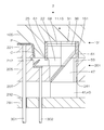
- FIG. 9 is a cross-sectional view of an essential part of the injection mold 3 according to the third embodiment of the present invention in a closed state.
- FIG. 11 and FIG. 12 are cross-sectional views of the main part of the injection mold 3 according to the third embodiment of the present invention after the gate is cut, when the mold opening is completed, and when the molded product P is pushed up.
- the injection mold 3 of the third embodiment includes a fixed mold 101 that molds a molded product P, a movable mold 201, and a gate cutting device 11 that cuts a gate.
- the injection mold 1 of the first embodiment Similarly, the gate G can be cut with the parting surface completely closed.
- the gate cutting device 11 is attached to the fixed mold 101, whereas in the injection mold 3 of the third embodiment, the gate cutting device 11 is attached to the movable mold 201. It is done.
- the fixed mold 101 has a fixed-side mounting plate (not shown) and a fixed-side mold plate 105, and the fixed-side mold plate 105 is provided with a cavity surface 108 that forms the outer surface of the molded product P. Further, the fixed-side template 105 is provided with a receiving portion 151 that communicates with the bottom surface 107 of the fixed-side template 105 and into which the upper portion of the holder 61 of the gate cutting device 11 is fitted.
- the accommodating portion 151 is a substantially rectangular recess when viewed from the front, and the ceiling surface 152 of the accommodating portion 151 is provided in parallel with the bottom surface 107 of the fixed-side template 105.
- the movable mold 201 has a movable side mold plate 205, a movable side insert 221 fixed to the movable side mold plate 205, and a movable side receiving plate 231, and the movable side receiving plate 231 is not shown in the drawing. It is configured to be movable away from the fixed side mold plate 205 from the plate driving means.
- the movable side receiving plate driving means can be configured in the same manner as the fixed side mold plate driving means 121 of the first embodiment.
- a core surface 223 that forms the inner surface of the molded product P is provided on the outer periphery of the movable side insert 221.
- the fixed-side template 205 is provided with a receiving portion 209 that communicates with the upper surface 206 and into which the lower portion of the slide cutter 15 and the holder 61 of the gate cutting device 11 is fitted. Further, the fixed-side template 205 is provided with an accommodating portion 241 that accommodates the holding piece 41. The accommodating portion 241 is provided so as to communicate with the accommodating portion 209 and to communicate with the bottom surface 207 of the fixed side template 205.
- the piece member 47 of the holding piece 41 has a trapezoidal shape in which the left side surface of the rectangular block member is cut obliquely and the upper surface is narrower than the lower surface in a front view of FIG.
- the holding piece 41 is fixed to the movable side receiving plate 231 so that the bottom surface of the base 45 is in contact with the upper surface 232 of the movable side receiving plate 231 by a mounting bolt (not shown).
- the mold closed molten resin is injected from an injection device (not shown), and the resin is supplied from a sprue (not shown) provided to the fixed mold 101 to a gate portion provided to the runner R and the slide cutter 15.
- the cavity C is filled via 26.
- the state where the mold is closed refers to the state of FIG. 9 in which the fixed mold 101 and the movable mold 201 are in contact with each other and the parting surface is closed.
- the parting surfaces are the bottom surface 107 of the fixed-side template 105 and the top surface 206 of the movable-side template 205.
- the molded product P is taken out through the pressure holding and cooling process, but the mold opening is performed as follows.
- the movable side receiving plate 231 is retracted by the movable side receiving plate driving means (not shown) with the parting surface closed.
- the movement of the movable side receiving plate 231 means that the movable side receiving plate 231 moves away from the movable side mold plate 205 and shifts from the state shown in FIGS. 9 to 10.
- the holding piece 41 When the movable side receiving plate 231 moves backward, the holding piece 41 also moves backward, so that the sliding piece 31 engaged with the holding piece 41 is guided by the concave portion 68 that is the sliding piece guide of the holder 61 and horizontally moves to the right side. Accordingly, the cutter 21 also slides to the right while being sandwiched between the bottom surface 107 of the fixed-side template 105 and the bottom surface 210 of the housing portion 209, and the gate G is cut (see FIG. 10).
- the gate G is cut at an initial stage when the fixed side receiving plate 231 starts to retract.
- the resin of the runner R does not change from the state before the gate G is cut.
- the movable side receiving plate 231 continues to retract until the movement is blocked by a stop bolt (not shown).
- the slide cutter 15 slides to the right with the vertical surface 28 of the gate portion 26 of the cutter 21 hooked to the tip of the resin of the runner R from which the gate G has been cut. Since the portion is pulled to the right side, a part of the resin is detached from the runner R (see FIG. 10).
- the movable mold 201 retracts from the fixed mold 101, and the parting surface opens (see FIG. 11). Subsequently, the resin of the molded product P and the runner R is ejected by the ejector pins 301 and 302 (see FIG. 12). As a result, the resin of the molded product P and the runner R from which the gate G has been cut is recovered.
- the slide cutter 15 is slid to cut the gate G by retracting the movable side receiving plate 231 prior to mold opening. That is, in the injection mold 3 of the third embodiment, the gate G is cut in the closed state as in the case of the injection mold 1 of the first embodiment, so that the gate G can be reliably and cleanly cut. it can.
- the injection mold 3 of the third embodiment like the injection mold 1 of the first embodiment, incorporates a compact and unitized gate cutting device 11 so that the injection mold 3 can be made compact. It can be manufactured at low cost.
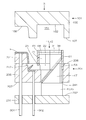
- FIG. 13 is a cross-sectional view of a main part of the injection mold 4 according to the fourth embodiment of the present invention in a closed state.
- FIGS. 14, 15 and 16 are cross-sectional views of the main part when the gate of the injection mold 4 according to the fourth embodiment of the present invention is cut, when the mold opening is completed, and when the molded product P is pushed up.
- the injection mold 4 of the fourth embodiment has the same basic configuration as the injection mold 3 of the third embodiment, while the mounting position of the gate cutting device 11 is the same as that of the injection mold 3 of the third embodiment. different.
- the gate cutting device 11 is positioned outside the molded product P, whereas in the injection mold 4 of the fourth embodiment, the gate cutting device 11 is molded.
- the inside of the molded product P is in a region surrounded by the outer periphery of the molded product P in a plan view of the molded product P.
- the movable side insert 221 that forms the core surface 223 of the molded product P is used. Is directly below.
- the gate cutting device 11 is attached to the movable mold plate 205 so as to be sandwiched between the movable insert 221 and the movable mold plate 205. For this reason, there is no accommodating part 151 of the stationary side mold plate 105 seen in the injection mold 3 of the third embodiment.
- the fixed-side template 105 is provided with a recess 155 into which the cutter tip 25 is fitted. The recess 155 communicates with the cavity surface 108 that forms the outer surface of the molded product P.
- the movable mold 201 has a movable side mold plate 205, a movable side insert 221 fixed to the movable side mold plate 205, and a movable side receiving plate 231, and the movable side receiving plate 231 is not shown in the drawing. It is configured to be movable away from the fixed side mold plate 205 from the plate driving means.
- the movable side receiving plate driving means can be configured in the same manner as the fixed side mold plate driving means 121 of the first embodiment.
- a core surface 223 that forms the inner surface of the molded product P is provided on the outer periphery of the movable side insert 221.
- a receiving portion 209 into which the cutter 21 and the lower portion of the holder 61 are fitted is provided in the fixed-side template 205 located immediately below the movable-side insert 221.
- the accommodating portion 209 is provided so as to communicate with the upper surface 206 of the fixed side template 205.
- the fixed-side template 205 includes an accommodating portion 241 that accommodates the holding piece 41.
- the accommodating portion 241 is provided so as to communicate with the accommodating portion 209 and to communicate with the bottom surface 207 of the fixed side template 205.
- the piece member 47 of the holding piece 41 has a trapezoidal shape in which the right side surface of the rectangular block member is cut obliquely and the upper surface is narrower than the lower surface in a front view of FIG.
- the holding piece 41 is fixed to the movable side receiving plate 231 so that the bottom surface of the base 45 is in contact with the upper surface 232 of the movable side receiving plate 231 by a mounting bolt (not shown).
- the operation of the injection mold 4 is the same as that of the injection mold 3 although the slide direction of the cutter 21 is opposite to that of the injection mold 3.
- the mold closed With the mold closed, molten resin is injected from an injection device (not shown), and the resin is supplied from a sprue (not shown) provided to the fixed mold 101 to a gate portion provided to the runner R and the slide cutter 15.
- the cavity C is filled via 26.
- the state where the mold is closed refers to the state of FIG. 13 in which the fixed mold 101 and the movable mold 201 are in contact with each other and the parting surface is closed.
- the parting surfaces are the bottom surface 107 of the fixed-side template 105 and the top surface 206 of the movable-side template 205.
- the molded product P is taken out through the pressure holding and cooling process, but the mold opening is performed as follows.
- the movable side receiving plate 231 is retracted by the movable side receiving plate driving means (not shown) with the parting surface closed.
- the sliding piece 31 engaged with the holding piece 41 is guided by the concave portion 68 which is the sliding piece guide of the holder 61 and horizontally moves to the left side.
- the cutter 21 slides to the left while being sandwiched between the bottom surface 224 of the movable side insert and the bottom surface 210 of the housing portion 209, and the gate portion 26 crosses the gate G and cuts the gate G.
- a blade is provided at the end of the inclined surface 27 of the gate portion 26 of the cutter 21 on the cavity side.
- the gate G is cut at an initial stage when the fixed side receiving plate 231 starts to retract.
- the resin of the runner R does not change from the state before the gate G is cut.
- the movable side receiving plate 231 continues to retract until the movement is blocked by a stop bolt (not shown).
- the slide cutter 15 slides to the left in a state where the inclined surface 27 of the gate portion 26 of the cutter 21 is hooked on the front end portion of the resin of the runner R from which the gate G is cut. Since the portion is pulled to the left side, a part of the resin is detached from the runner R (see FIG. 14).
- the movable mold 201 retracts from the fixed mold 101, and the parting surface opens (see FIG. 15). Subsequently, the resin of the molded product P and the runner R is ejected by the ejector pins 301 and 302 (see FIG. 16). As a result, the resin of the molded product P and the runner R from which the gate G has been cut is recovered.
- the movable side receiving plate 231 is retracted prior to opening the mold to slide the slide cutter 15 to cut the gate G. That is, in the injection mold 4 of the fourth embodiment, the gate G is cut in the closed state as in the case of the injection mold 1 of the first embodiment, so that the gate G can be cut reliably and cleanly. it can.
- the gate G is cut on the inclined surface 27 side of the gate portion 26, so the gate G is smooth and clean. Can be cut. Further, the injection mold 4 of the fourth embodiment is such that the gate cutting device 11 is located inside the molded product P, and the cutter 21 does not protrude outside the molded product P even when the gate is cut. 4 can be made more compact.
- FIG. 17 is a cross-sectional view of the main part of the injection mold 5 according to the fifth embodiment of the present invention in a closed state.
- 18, 19, and 20 are cross-sectional views of main parts when the gate of the injection mold 5 according to the fifth embodiment of the present invention is cut, when the mold opening is completed, and when the molded product P is pushed up.
- the same components as those of the injection mold 1 of the first embodiment shown in FIGS. 1 to 4 are denoted by the same reference numerals and description thereof is omitted.
- the injection mold 5 of the fifth embodiment includes a fixed mold 101 and a movable mold 201 that mold the molded product P, and a gate cutting device 12 that cuts the gate.
- the gate cutting device 12 is attached to the fixed mold 101.
- the gate cutting device 12 used here has the same basic structure as the gate cutting device 11, the operation mechanism of the gate cutting device 11 is different, and accordingly, the structure of the gate cutting device 12 is also partially different.
- the fixed mold 101 includes a fixed-side mounting plate 102 and a fixed-side mold plate 105.
- the fixed-side mold plate 105 includes a housing portion 109 that houses the gate cutting device 12 and a gate that operates the gate cutting device 12.
- An accommodating portion 116 that accommodates the cutting device driving means 161 and a cutter accommodating portion 117 that accommodates the cutter 21 are provided.
- the accommodating portion 116 is a recess provided so as to communicate with the upper surface of the fixed-side template 105, and the accommodating portion 109 is provided so as to communicate with the accommodating portion 116 and penetrate the fixed-side template 105.
- the cutter accommodating portion 117 is a recess in which the cutter 21 is accommodated when the mold is closed, and is provided on the bottom surface 107 of the fixed-side mold plate 105 so as to communicate with the accommodating portion 109 and the cavity surface 108.
- the lateral width (left-right direction) of the accommodating portion 116 is larger than the lateral width of the accommodating portion 109, and the accommodating portion 109 is located on the left side of the accommodating portion 116.
- the position of the accommodating portion 109 relative to the accommodating portion 116 is not particularly limited.
- the fixed-side template 105 is provided with an insertion hole 118 that penetrates the fixed-side template 105 and communicates with the accommodating portion 116 and through which the return pin 167 is inserted.
- the gate cutting device driving means 161 is inserted through the insertion hole 118, a horizontally long connecting member 162 disposed in the accommodating portion 116, a spring 164 connected and disposed between the connecting member 162 and the fixed side mounting plate 102. And a return pin 167 connected to the connecting member 162, and operates the gate cutting device 12 in conjunction with mold opening.
- the lower end 168 of the return pin 167 is in contact with the upper surface 206 of the movable side template 205 in the mold closed state.
- the gate cutting device 12 is a device that cuts the gate G connected to the molded product P, and a slide cutter 16 that cuts the gate G, and a holding piece 42 that is slidably engaged with the slide cutter 16 and slides the slide cutter 16. And a holder 62 for accommodating the holding piece 42 so as to be able to advance and retreat.
- the basic configuration of the slide cutter 16 is the same as that of the slide cutter 15 of the first embodiment, but the structure of the slide piece 32, the holding piece 42, and the holder 62 is the same as the slide piece 31, the holding piece 41, and the first embodiment. Different from the holder 61.
- the sliding piece 32 is slidably engaged with the holding piece 42, moves with the movement of the holding piece 42, and moves the attached cutter 21 forward and backward.
- the sliding piece 32 has a trapezoidal shape in which the right side surface of the rectangular block member is cut obliquely (see FIG. 18).
- the sliding piece 32 is provided with a dovetail groove 36 into which a ridge 52 provided at the lower part of the holding piece 42 is slidably fitted in the upper part of the front outer wall 37 and the rear outer wall, and is provided in the holder 62 on the right side surface. And a ridge 39 that is slidably fitted into the inclined groove 70.
- the holding piece 42 is slidably engaged with the slide cutter 16 and advances and retreats in the vertical direction to slide the slide cutter 16 in the horizontal direction.
- the holding piece 42 includes a rectangular block-shaped piece member 48 that is slidably engaged with the sliding piece 32, and a rod-shaped connecting member 46.
- a ridge 52 that is slidably fitted into a dovetail groove 36 provided on the upper portion of the holding piece 32 is provided. Further, the front outer wall and the rear outer wall of the piece member 48 are provided with ridges (not shown) that are slidably fitted into concave grooves (not shown) that are holding piece guides provided on the holder 62.
- the connecting member 46 is a member corresponding to the base 45 of the holding piece 41 of the first embodiment, and is connected to the bottom surface of the connecting member 162 and the top surface of the piece member 48.
- the holder 62 accommodates the holding piece 42 so as to be able to advance and retreat, guides the holding piece 42 in the vertical direction, and guides the slide cutter 16 in the cutting direction of the gate G.
- the holder 62 has a U-shaped cross section like the holder 61.
- the holder 62 is attached to the accommodating portion 109 of the fixed-side template 105 so that the lower end 75 is flush with the upper end of the cutter accommodating portion 117.
- the holder 62 is provided with an inclined groove 70 that engages with the ridge 39 of the sliding piece 32 of the slide cutter 16 on the inner wall on the front side (not shown) and the inner wall on the back side when FIG. 17 is viewed from the front.
- a concave groove (not shown) into which a protrusion (not shown) of the holding piece 42 for guiding the piece 42 in the vertical direction is provided in the vertical direction.
- the slide cutter 16 is slidably engaged with the holding piece 42 and is incorporated in the holder 62 in a state where the cutter 21 protrudes from the holder 62.
- the upper surface 29 of the main body portion 22 and the distal end portion 25 abuts slidably on the upper surface of the cutter accommodating portion 117 of the fixed-side mold plate 105, and the bottom surface of the main body portion 23 and the bottom surface of the sliding piece 32.
- 33 abuts on the upper surface 206 of the movable side template 205.
- the state where the mold is closed refers to the state of FIG. 17 in which the fixed mold 101 and the movable mold 201 are in contact with each other and the parting surface is closed.
- the parting surfaces are the bottom surface 107 of the fixed-side template 105 and the top surface 206 of the movable-side template 205.
- the fixed side mounting plate 102 and the fixed side mold plate 105 are in contact with each other, and the spring 164 of the gate cutting device driving means 161 is in a compressed state.
- the molded product P is taken out through the pressure holding and cooling process, but the mold opening is performed as follows.
- the movable mold 201 is retracted (lowered) from the fixed mold 101 and the mold opening is started (see FIG. 18).
- the spring 164 of the gate cutting device driving means 161 is extended to protrude the holding piece 42. Accordingly, the sliding piece 32 engaged with the holding piece 42 is guided by the inclined groove 70 and the holding piece 42 provided in the holder 62 and horizontally moved to the right side. Accordingly, the cutter 21 slides to the right while sliding on the upper surface 206 of the movable side template 205, and the gate portion 26 crosses the gate G and cuts the gate G.
- the gate G is cut at an initial stage when the movable mold 201 starts to retract.
- the resin of the runner R does not change from the state before the gate G is cut.
- the protrusion of the holding piece 42 is continued until the connecting member 162 comes into contact with the bottom surface of the accommodating portion 116.
- the slide cutter 16 slides to the right with the vertical surface 28 of the gate portion 26 of the cutter 21 hooked to the tip of the resin of the runner R from which the gate G has been cut. Since the portion is pulled to the right side, a part of the resin is detached from the runner R (see FIG. 18).
- the movable side template 205 moves back to a position where the molded product P can be taken out (see FIG. 19), and the resin of the molded product P and the runner R is ejected by the ejector pins 301 and 302 (see FIG. 20). As a result, the resin of the molded product P and the runner R from which the gate G has been cut is recovered.
- the gate cutting device 12 that moves the slide cutter 16 in conjunction with the mold opening and cuts the gate G is disposed in the fixed mold 105 in a compact manner. Further, since the gate cutting device 12 is unitized, it can be easily incorporated into an injection mold, and an injection mold including the gate cutting device can be manufactured compactly and inexpensively. In the injection mold 5 of the fifth embodiment, since the fixed side mounting plate 102 and the fixed side mold plate 105 are in a fixed state, they can be applied not only to a cold runner but also to a hot runner.
- the gate cutting device and the molding die according to the present invention have been described above using the injection molds 1, 2, 3, 4, and 5 according to the first to fifth embodiments.
- the molding die is not limited to the above-described embodiment, and can be used by being modified without changing the gist.
- the sliding piece 31 is provided with the dovetail groove 36
- the holding piece 41 is provided with the ridge 52, and these are slidably engaged with each other.
- the cross-sectional shape of the dovetails and ridges that engage with each other is not limited to the rectangular shape shown in the figure, the cross-section of the fitting portion or the engaging portion is circular, It may be a triangle or the like.
- the engaging means of the holder, the sliding piece, and the holding piece are not limited to the above embodiment, and for example, a linear guide or the like may be used. .
- the holders 61 and 62 are separate from the fixed mold 101 or the movable mold 201.
- the holder may be provided integrally with the fixed mold and / or the movable mold.
- the gate G shown in the injection molds 1, 2, 3, 4 and 5 of the first to fifth embodiments is of a type called an overlap gate, but the gate cutting device and the molding die of the present invention are used.
- the type of the gate G is not particularly limited.
- the spring 122 is used as a driving source for the fixed-side template 105, but another elastic body that can expand and contract may be used instead of the spring.
- the molded product P that can be molded in the molding die of the present invention is not particularly limited, and may be a molded product having an undercut portion.
- R chamfering, C chamfering, or the like may be applied to the corners and side ridges of each constituent member.
- each structural member used for the gate cutting device and the molding die of the present invention is not limited to a specific material, and the members used for the known gate cutting device and the molding die are not limited to specific materials. A material similar to the material may be used as appropriate. However, it is preferable to use a material having a good slidability or a material subjected to a surface treatment having a good slidability for the sliding surface of each constituent member. Each sliding surface is not limited to surface contact, and may be line contact or point contact.
- the gate cutting device and the molding die of the present invention can be applied to a die that opens and closes horizontally, vertically, or in other directions. Further, the gate cutting device and the molding die of the present invention can be suitably used for a mold die such as a die-casting die, a mold press molding die, and the like in addition to the injection molding die.
Landscapes
- Engineering & Computer Science (AREA)
- Manufacturing & Machinery (AREA)
- Mechanical Engineering (AREA)
- Moulds For Moulding Plastics Or The Like (AREA)
Abstract
L'objectif de la présente invention est de fournir un mécanisme de coupe de porte qui est compact et qui est facile à incorporer dans une matrice fixe ou une matrice mobile. Ce dispositif de coupe de porte est pourvu d'un dispositif de coupe coulissant 15 pour couper une porte G, d'une pièce de retenue 41 qui vient en prise de façon coulissante avec le dispositif de coupe coulissant 15 et amène le dispositif de coupe coulissant 15 à coulisser, et un support 61 qui reçoit la pièce de retenue 41 de manière à pouvoir avancer et reculer, et qui est fixé ou formé d'un seul tenant avec une matrice fixe 101 ou une matrice mobile 201 : le support 61 comprenant un guide qui guide le dispositif de coupe coulissant 15 dans une direction pour couper la porte G ; le dispositif de coupe coulissant 15 est pourvu d'une partie de porte 26 comprenant un trou traversant ; dans un état fermé de moule, la partie de porte 26 communique avec un canal R et une cavité C ; la partie de porte 26 est pourvue d'une lame ; et le mouvement de la pièce de retenue 41 amène le dispositif de coupe coulissant 15 à coulisser et la porte G à être découper par la partie de porte 26.
Priority Applications (2)
| Application Number | Priority Date | Filing Date | Title |
|---|---|---|---|
| PCT/JP2018/022848 WO2019239571A1 (fr) | 2018-06-15 | 2018-06-15 | Dispositif de coupe de porte et matrice de moulage |
| JP2020525050A JP7097101B2 (ja) | 2018-06-15 | 2018-06-15 | ゲート切断装置及び成形用金型 |
Applications Claiming Priority (1)
| Application Number | Priority Date | Filing Date | Title |
|---|---|---|---|
| PCT/JP2018/022848 WO2019239571A1 (fr) | 2018-06-15 | 2018-06-15 | Dispositif de coupe de porte et matrice de moulage |
Publications (1)
| Publication Number | Publication Date |
|---|---|
| WO2019239571A1 true WO2019239571A1 (fr) | 2019-12-19 |
Family
ID=68843098
Family Applications (1)
| Application Number | Title | Priority Date | Filing Date |
|---|---|---|---|
| PCT/JP2018/022848 Ceased WO2019239571A1 (fr) | 2018-06-15 | 2018-06-15 | Dispositif de coupe de porte et matrice de moulage |
Country Status (2)
| Country | Link |
|---|---|
| JP (1) | JP7097101B2 (fr) |
| WO (1) | WO2019239571A1 (fr) |
Cited By (2)
| Publication number | Priority date | Publication date | Assignee | Title |
|---|---|---|---|---|
| CN115674594A (zh) * | 2022-09-23 | 2023-02-03 | 亿和精密工业(威海)有限公司 | 一种三板模滑块冷切结构 |
| JP7629629B2 (ja) | 2021-03-01 | 2025-02-14 | 株式会社テクノクラーツ | ゲート切断装置及び成形用金型 |
Citations (5)
| Publication number | Priority date | Publication date | Assignee | Title |
|---|---|---|---|---|
| JPH04102825U (ja) * | 1991-02-18 | 1992-09-04 | 市光工業株式会社 | 熱可塑性プラスチツク射出成形用の金型内ゲートカツトピン |
| JPH07323447A (ja) * | 1994-06-01 | 1995-12-12 | Toyo Mach & Metal Co Ltd | 射出成形機 |
| JP2006001145A (ja) * | 2004-06-17 | 2006-01-05 | San Seimitsu Kako Kenkyusho:Kk | 射出成形用金型、および射出成形部品の製造方法 |
| JP2006334980A (ja) * | 2005-06-03 | 2006-12-14 | Aron Kasei Co Ltd | 射出成形用金型のゲ−トカット法およびその装置 |
| JP2015074138A (ja) * | 2013-10-08 | 2015-04-20 | 小島プレス工業株式会社 | 射出成形装置 |
-
2018
- 2018-06-15 WO PCT/JP2018/022848 patent/WO2019239571A1/fr not_active Ceased
- 2018-06-15 JP JP2020525050A patent/JP7097101B2/ja not_active Expired - Fee Related
Patent Citations (5)
| Publication number | Priority date | Publication date | Assignee | Title |
|---|---|---|---|---|
| JPH04102825U (ja) * | 1991-02-18 | 1992-09-04 | 市光工業株式会社 | 熱可塑性プラスチツク射出成形用の金型内ゲートカツトピン |
| JPH07323447A (ja) * | 1994-06-01 | 1995-12-12 | Toyo Mach & Metal Co Ltd | 射出成形機 |
| JP2006001145A (ja) * | 2004-06-17 | 2006-01-05 | San Seimitsu Kako Kenkyusho:Kk | 射出成形用金型、および射出成形部品の製造方法 |
| JP2006334980A (ja) * | 2005-06-03 | 2006-12-14 | Aron Kasei Co Ltd | 射出成形用金型のゲ−トカット法およびその装置 |
| JP2015074138A (ja) * | 2013-10-08 | 2015-04-20 | 小島プレス工業株式会社 | 射出成形装置 |
Cited By (3)
| Publication number | Priority date | Publication date | Assignee | Title |
|---|---|---|---|---|
| JP7629629B2 (ja) | 2021-03-01 | 2025-02-14 | 株式会社テクノクラーツ | ゲート切断装置及び成形用金型 |
| CN115674594A (zh) * | 2022-09-23 | 2023-02-03 | 亿和精密工业(威海)有限公司 | 一种三板模滑块冷切结构 |
| CN115674594B (zh) * | 2022-09-23 | 2025-07-01 | 亿和精密工业(威海)有限公司 | 一种三板模滑块冷切结构 |
Also Published As
| Publication number | Publication date |
|---|---|
| JPWO2019239571A1 (ja) | 2021-06-24 |
| JP7097101B2 (ja) | 2022-07-07 |
Similar Documents
| Publication | Publication Date | Title |
|---|---|---|
| JP7007690B2 (ja) | スライド機構、可動型及び成形用金型 | |
| JP4628476B2 (ja) | 射出成型装置 | |
| JP7097635B2 (ja) | アンダーカット処理機構及び成形用金型 | |
| CN105313282A (zh) | 一种叠层注塑模具侧浇口自动切除机构 | |
| WO2021044503A1 (fr) | Mécanisme coulissant, matrice fixe, matrice mobile et moule de formage | |
| JP6892090B2 (ja) | アンダーカット処理機構及び成形用金型 | |
| JP4273401B2 (ja) | 射出成形用金型 | |
| WO2019239571A1 (fr) | Dispositif de coupe de porte et matrice de moulage | |
| JP5319392B2 (ja) | 金型、および成形品の製造方法 | |
| JP2006027229A (ja) | 成形装置 | |
| JPH07223244A (ja) | 樹脂成形用金型装置 | |
| JP2009113221A (ja) | 射出成型用金型 | |
| JP2003245955A (ja) | 射出成形金型 | |
| JP2018047667A (ja) | スライドコアユニット及び当該スライドコアユニットを有する成形用金型 | |
| JP7629629B2 (ja) | ゲート切断装置及び成形用金型 | |
| JP2004306295A (ja) | 成形用金型 | |
| JP2009214478A (ja) | 射出成形装置及び射出成形品の成形方法 | |
| JP2017013274A (ja) | 射出成形装置 | |
| JP2003245957A (ja) | 射出成形金型 | |
| JP2966707B2 (ja) | 射出成形方法及び射出成形金型の構造 | |
| CN223657482U (zh) | 一种滑块移动装置及双色注塑模具 | |
| JPH07125023A (ja) | 樹脂成形装置 | |
| JP6199346B2 (ja) | 成形品の突き出しに特徴を有する成形方法および射出成形機 | |
| JP5628624B2 (ja) | 成形金型 | |
| JP2006289688A (ja) | 射出成形用金型および射出成形方法 |
Legal Events
| Date | Code | Title | Description |
|---|---|---|---|
| 121 | Ep: the epo has been informed by wipo that ep was designated in this application |
Ref document number: 18922502 Country of ref document: EP Kind code of ref document: A1 |
|
| ENP | Entry into the national phase |
Ref document number: 2020525050 Country of ref document: JP Kind code of ref document: A |
|
| NENP | Non-entry into the national phase |
Ref country code: DE |
|
| 122 | Ep: pct application non-entry in european phase |
Ref document number: 18922502 Country of ref document: EP Kind code of ref document: A1 |