WO2019243903A1 - Dispositif coulissant destiné à un siège de véhicule doté d'un système de verrouillage amélioré - Google Patents
Dispositif coulissant destiné à un siège de véhicule doté d'un système de verrouillage amélioré Download PDFInfo
- Publication number
- WO2019243903A1 WO2019243903A1 PCT/IB2019/053183 IB2019053183W WO2019243903A1 WO 2019243903 A1 WO2019243903 A1 WO 2019243903A1 IB 2019053183 W IB2019053183 W IB 2019053183W WO 2019243903 A1 WO2019243903 A1 WO 2019243903A1
- Authority
- WO
- WIPO (PCT)
- Prior art keywords
- locking
- sliding device
- locking pins
- support plate
- releasing
- Prior art date
- Legal status (The legal status is an assumption and is not a legal conclusion. Google has not performed a legal analysis and makes no representation as to the accuracy of the status listed.)
- Ceased
Links
Images




Classifications
-
- B—PERFORMING OPERATIONS; TRANSPORTING
- B60—VEHICLES IN GENERAL
- B60N—SEATS SPECIALLY ADAPTED FOR VEHICLES; VEHICLE PASSENGER ACCOMMODATION NOT OTHERWISE PROVIDED FOR
- B60N2/00—Seats specially adapted for vehicles; Arrangement or mounting of seats in vehicles
- B60N2/02—Seats specially adapted for vehicles; Arrangement or mounting of seats in vehicles the seat or part thereof being movable, e.g. adjustable
- B60N2/04—Seats specially adapted for vehicles; Arrangement or mounting of seats in vehicles the seat or part thereof being movable, e.g. adjustable the whole seat being movable
- B60N2/06—Seats specially adapted for vehicles; Arrangement or mounting of seats in vehicles the seat or part thereof being movable, e.g. adjustable the whole seat being movable slidable
- B60N2/08—Seats specially adapted for vehicles; Arrangement or mounting of seats in vehicles the seat or part thereof being movable, e.g. adjustable the whole seat being movable slidable characterised by the locking device
- B60N2/0831—Movement of the latch
- B60N2/0862—Movement of the latch sliding
- B60N2/0875—Movement of the latch sliding in a vertical direction
-
- B—PERFORMING OPERATIONS; TRANSPORTING
- B60—VEHICLES IN GENERAL
- B60N—SEATS SPECIALLY ADAPTED FOR VEHICLES; VEHICLE PASSENGER ACCOMMODATION NOT OTHERWISE PROVIDED FOR
- B60N2/00—Seats specially adapted for vehicles; Arrangement or mounting of seats in vehicles
- B60N2/02—Seats specially adapted for vehicles; Arrangement or mounting of seats in vehicles the seat or part thereof being movable, e.g. adjustable
- B60N2/04—Seats specially adapted for vehicles; Arrangement or mounting of seats in vehicles the seat or part thereof being movable, e.g. adjustable the whole seat being movable
- B60N2/06—Seats specially adapted for vehicles; Arrangement or mounting of seats in vehicles the seat or part thereof being movable, e.g. adjustable the whole seat being movable slidable
- B60N2/07—Slide construction
- B60N2/0702—Slide construction characterised by its cross-section
- B60N2/0715—C or U-shaped
-
- B—PERFORMING OPERATIONS; TRANSPORTING
- B60—VEHICLES IN GENERAL
- B60N—SEATS SPECIALLY ADAPTED FOR VEHICLES; VEHICLE PASSENGER ACCOMMODATION NOT OTHERWISE PROVIDED FOR
- B60N2/00—Seats specially adapted for vehicles; Arrangement or mounting of seats in vehicles
- B60N2/02—Seats specially adapted for vehicles; Arrangement or mounting of seats in vehicles the seat or part thereof being movable, e.g. adjustable
- B60N2/04—Seats specially adapted for vehicles; Arrangement or mounting of seats in vehicles the seat or part thereof being movable, e.g. adjustable the whole seat being movable
- B60N2/06—Seats specially adapted for vehicles; Arrangement or mounting of seats in vehicles the seat or part thereof being movable, e.g. adjustable the whole seat being movable slidable
- B60N2/07—Slide construction
- B60N2/0722—Constructive details
- B60N2/0727—Stop members for limiting sliding movement
-
- B—PERFORMING OPERATIONS; TRANSPORTING
- B60—VEHICLES IN GENERAL
- B60N—SEATS SPECIALLY ADAPTED FOR VEHICLES; VEHICLE PASSENGER ACCOMMODATION NOT OTHERWISE PROVIDED FOR
- B60N2/00—Seats specially adapted for vehicles; Arrangement or mounting of seats in vehicles
- B60N2/02—Seats specially adapted for vehicles; Arrangement or mounting of seats in vehicles the seat or part thereof being movable, e.g. adjustable
- B60N2/04—Seats specially adapted for vehicles; Arrangement or mounting of seats in vehicles the seat or part thereof being movable, e.g. adjustable the whole seat being movable
- B60N2/06—Seats specially adapted for vehicles; Arrangement or mounting of seats in vehicles the seat or part thereof being movable, e.g. adjustable the whole seat being movable slidable
- B60N2/08—Seats specially adapted for vehicles; Arrangement or mounting of seats in vehicles the seat or part thereof being movable, e.g. adjustable the whole seat being movable slidable characterised by the locking device
-
- B—PERFORMING OPERATIONS; TRANSPORTING
- B60—VEHICLES IN GENERAL
- B60N—SEATS SPECIALLY ADAPTED FOR VEHICLES; VEHICLE PASSENGER ACCOMMODATION NOT OTHERWISE PROVIDED FOR
- B60N2/00—Seats specially adapted for vehicles; Arrangement or mounting of seats in vehicles
- B60N2/02—Seats specially adapted for vehicles; Arrangement or mounting of seats in vehicles the seat or part thereof being movable, e.g. adjustable
- B60N2/04—Seats specially adapted for vehicles; Arrangement or mounting of seats in vehicles the seat or part thereof being movable, e.g. adjustable the whole seat being movable
- B60N2/06—Seats specially adapted for vehicles; Arrangement or mounting of seats in vehicles the seat or part thereof being movable, e.g. adjustable the whole seat being movable slidable
- B60N2/08—Seats specially adapted for vehicles; Arrangement or mounting of seats in vehicles the seat or part thereof being movable, e.g. adjustable the whole seat being movable slidable characterised by the locking device
- B60N2/0806—Seats specially adapted for vehicles; Arrangement or mounting of seats in vehicles the seat or part thereof being movable, e.g. adjustable the whole seat being movable slidable characterised by the locking device with pin alignment systems, e.g. with at least one of a plurality of locking pins always aligned w.r.t. at least one of a plurality of pin-receiving elements
-
- B—PERFORMING OPERATIONS; TRANSPORTING
- B60—VEHICLES IN GENERAL
- B60N—SEATS SPECIALLY ADAPTED FOR VEHICLES; VEHICLE PASSENGER ACCOMMODATION NOT OTHERWISE PROVIDED FOR
- B60N2/00—Seats specially adapted for vehicles; Arrangement or mounting of seats in vehicles
- B60N2/02—Seats specially adapted for vehicles; Arrangement or mounting of seats in vehicles the seat or part thereof being movable, e.g. adjustable
- B60N2/04—Seats specially adapted for vehicles; Arrangement or mounting of seats in vehicles the seat or part thereof being movable, e.g. adjustable the whole seat being movable
- B60N2/06—Seats specially adapted for vehicles; Arrangement or mounting of seats in vehicles the seat or part thereof being movable, e.g. adjustable the whole seat being movable slidable
- B60N2/08—Seats specially adapted for vehicles; Arrangement or mounting of seats in vehicles the seat or part thereof being movable, e.g. adjustable the whole seat being movable slidable characterised by the locking device
- B60N2/0812—Location of the latch
- B60N2/0818—Location of the latch inside the rail
-
- B—PERFORMING OPERATIONS; TRANSPORTING
- B60—VEHICLES IN GENERAL
- B60N—SEATS SPECIALLY ADAPTED FOR VEHICLES; VEHICLE PASSENGER ACCOMMODATION NOT OTHERWISE PROVIDED FOR
- B60N2/00—Seats specially adapted for vehicles; Arrangement or mounting of seats in vehicles
- B60N2/02—Seats specially adapted for vehicles; Arrangement or mounting of seats in vehicles the seat or part thereof being movable, e.g. adjustable
- B60N2/04—Seats specially adapted for vehicles; Arrangement or mounting of seats in vehicles the seat or part thereof being movable, e.g. adjustable the whole seat being movable
- B60N2/06—Seats specially adapted for vehicles; Arrangement or mounting of seats in vehicles the seat or part thereof being movable, e.g. adjustable the whole seat being movable slidable
- B60N2/08—Seats specially adapted for vehicles; Arrangement or mounting of seats in vehicles the seat or part thereof being movable, e.g. adjustable the whole seat being movable slidable characterised by the locking device
- B60N2/0881—Activation of the latches by the control mechanism
-
- B—PERFORMING OPERATIONS; TRANSPORTING
- B60—VEHICLES IN GENERAL
- B60N—SEATS SPECIALLY ADAPTED FOR VEHICLES; VEHICLE PASSENGER ACCOMMODATION NOT OTHERWISE PROVIDED FOR
- B60N2/00—Seats specially adapted for vehicles; Arrangement or mounting of seats in vehicles
- B60N2/02—Seats specially adapted for vehicles; Arrangement or mounting of seats in vehicles the seat or part thereof being movable, e.g. adjustable
- B60N2/04—Seats specially adapted for vehicles; Arrangement or mounting of seats in vehicles the seat or part thereof being movable, e.g. adjustable the whole seat being movable
- B60N2/06—Seats specially adapted for vehicles; Arrangement or mounting of seats in vehicles the seat or part thereof being movable, e.g. adjustable the whole seat being movable slidable
- B60N2/08—Seats specially adapted for vehicles; Arrangement or mounting of seats in vehicles the seat or part thereof being movable, e.g. adjustable the whole seat being movable slidable characterised by the locking device
- B60N2/0881—Activation of the latches by the control mechanism
- B60N2/0887—Activation of the latches by the control mechanism with synchronised movements
Definitions
- the present invention relates to a sliding device for a vehicle seat provided with an improved locking arrangement.
- the present invention relates to a sliding device for a vehicle seat provided with a locking arrangement having a compact construction and an improved reliability.
- Vehicle seats generally have a sliding function for pushing or pulling the seat cushion in a forward or backward direction, a height adjustment function for adjusting the height of the seat cushion, and a reclining function for adjusting the inclination of the seat backrest relative to the seat cushion.
- the aforesaid sliding function is generally implemented by a sliding device which comprises a pair of parallel tracks, each of which comprises a lower rail attached to the vehicle floor and an upper rail attached to the vehicle seat, the upper rail being constrained to the lower rail, but being able to slide relative to said lower rail.
- the sliding device further comprises a locking arrangement for allowing / preventing a movement of the upper rails relative to the lower rails.
- Such locking arrangement is normally in a locking configuration, in which it prevents the upper rails from sliding with respect to the lower rails, thus avoiding accidental displacements of the seat with respect to the vehicle floor.
- Such locking arrangement normally comprises a pair of locking assemblies, one for each track.
- the sliding device is further provided with a releasing member which can be used by a user for moving the locking assemblies of the locking arrangement to an unlocking configuration, in which the upper rails are free to move relative to the lower rails, so that the position of the seat with respect to the vehicle floor can be adjusted.
- a releasing member can be made, for instance, as a “U”-shaped handle or towel bar having two substantially parallel arms, the end portions of which are configured to simultaneously act upon respective locking assemblies for driving them to their unlocking configuration.
- each locking assembly is connected to the respective upper rail and comprises one or more locking pins configured to penetrate into respective apertures of the lower rail and engage with the edge of said apertures.
- the size of said locking pins, the distance between said locking pins, the size of the apertures in the lower rails and the distance between said apertures are chosen so that at least one locking pin is always aligned with a corresponding aperture, so that it can penetrate into said aperture and engage the edge thereof.
- the size of said locking pins, the distance between said locking pins, the size of the apertures in the lower rails and the distance between said apertures are chosen so that at least a first locking pin is positioned so as to penetrate into a corresponding aperture and engage the forward side of the edge thereof and at least a second locking pin is positioned so as to penetrate into a corresponding aperture and engage the rearward side of the edge thereof, whereby a “chuckless” engagement is obtained.
- Such locking pins are normally biased, e.g. by means of springs, to a locking configuration, in which at least some of them engage respective apertures of the lower rails.
- a releasing member – such as a releasing towel bar or handle – is provided, which acts upon respective connecting members, one for each locking assembly: said connecting members, in turn, act upon the locking pins of the respective locking assembly for moving them to an unlocking configuration, in which they are disengaged from the apertures of the respective lower rail.
- the locking pins are generally provided with an enlarged head and the connecting members are provided with fork-shaped elements adapted to engage the pin heads for extracting said pins from the apertures of the lower rails.
- the connecting members connecting the releasing member to the locking assemblies are either partially or completely arranged outside the tracks of the sliding device.
- connecting members are exposed to dust and dirt, which may accumulate between the moving parts of these connecting members and cause malfunctioning thereof.
- Such dust and dirt may also penetrate into the tracks of the sliding device and interfere with the movement of the locking pins from their locking configuration to their unlocking configuration, and vice versa.
- Usual malfunctioning issues include increased release efforts, increased sliding efforts and noise issues, which may trigger users’ dissatisfaction.
- a main object of the present invention is to provide a sliding device for a vehicle seat provided with an improved locking arrangement having a compact structure.
- a further object of the present invention is to provide a sliding device for a vehicle seat provided with an improved locking arrangement showing an improved reliability, namely avoiding the risk of malfunctioning due to accumulation of dirt and dust close to the moving parts of said locking arrangement.
- the invention relates to sliding device for a vehicle seat which comprises a pair of parallel tracks, each including a lower rail, intended to be attached to the vehicle floor, and an upper rail, intended to be attached to the vehicle seat and slidably mounted to said lower rail, each lower rail comprising a plurality of apertures, aligned and equally spaced from one another along the longitudinal axis of said lower rail.
- the sliding device further comprises a locking arrangement which comprises a locking assembly associated to each track for selectively allowing / preventing a movement of said upper rails relative to said lower rails.
- Each locking assembly is connected to a respective upper rail and comprises one or more locking pins configured to penetrate into corresponding apertures of the respective lower rail and to engage the edges of said apertures, said locking pins being biased to a locking configuration, for instance by spring means.
- each locking assembly comprises a plurality of locking pins.
- such locking pins are sized and arranged so that, for any position of the upper rail relative to the lower rail, at least one locking pin is aligned with a corresponding aperture of the respective lower rail and can penetrate into said aperture and engage the edge thereof.
- the locking arrangement is further provided with a releasing assembly for simultaneously switching said locking assemblies from a locking configuration, in which the movement of the upper rails of the tracks relative to the respective lower rails is prevented, to an unlocking configuration, in which the movement of said upper rails relative to the respective lower rails is allowed.
- Said releasing assembly comprises a releasing member and a pair of connecting members, one for each locking assembly, each of said connecting members being in a force transmission connection with the releasing member, on one hand, and with the locking pins of the respective locking assembly, on the other hand.
- such connecting members are entirely received inside the respective tracks, and they are arranged between the upper rail and the lower rail of the respective track.
- This arrangement allows to obtain a compact structure, which turns out to be advantageous in packaging the sliding device with respect to the external release systems proposed in the prior solutions, in which the connecting members of the releasing assembly are arranged at least partially outside the respective tracks.
- each locking assembly comprises a support plate, which is fastened (e.g. welded and/or staked) to the respective upper rail and is provided with a window through which the locking pins can slide for moving from their unlocking configuration to their locking configuration, and vice versa.
- Each connecting member is correspondingly made as a spring plate which comprises an engaging portion for engagement with the releasing member, a driving portion for driving the locking pins from their locking configuration to their unlocking configuration, and a connecting portion for connection to the support plate of the locking assembly.
- the locking pins are provided with transversely projecting pegs and the driving portion of the spring plate comprises a window having a width larger than the diameter of the locking pins but smaller than the sum of the diameter of the locking pins and the length of the projecting pegs, so that the edge of the window of the driving portion of the spring plate can engage such pegs for driving the locking pins to their unlocking configuration.
- the releasing member is made as a “U”-shaped handle having two substantially parallel arms and the engaging portion of each spring plate is configured to receive the end portion of a respective arm of said releasing handle.
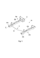
- Figure 1 is a perspective view of a sliding device according to the invention.
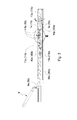
- Figure 2 is a cross-sectional view of the sliding device of Figure 1 taken along the line II-II;
- Figure 3a is an enlarged view of the detail III of Figure 2, illustrated in a first, locking configuration
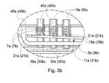
- Figure 3b is an enlarged view of the detail III of Figure 2, illustrated in a second, unlocking configuration
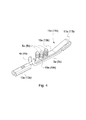
- Figure 4 is a perspective view of the connecting member of the locking assembly of Figure 2;
- Figure 5a partially shows, in a cross-sectional view, the locking arrangement of a sliding device according to a variant of the invention
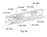
- Figure 5b partially shows, in a perspective, partially cut-away view, the locking arrangement of Figure 5a;
- Figure 6a shows a first locking configurations of the locking pins of the locking assembly of Figure 2;
- Figure 6b shows a second locking configurations of the locking pins of the locking assembly of Figure 2;
- Figure 6c shows a third locking configurations of the locking pins of the locking assembly of Figure 2.
- the sliding device 10 comprises a pair of parallel tracks 20a, 20b, each comprising a lower rail 30a, 30b, intended to be attached to the vehicle floor, and an upper rail 40a, 40b, intended to be attached to the frame of a vehicle seat.
- Each upper rail 40a, 40b is constrained to the respective lower rail 30a, 30b, but can slide relative to said lower rail.
- a locking arrangement In order to selectively allow / prevent a sliding movement of the upper rails relative to the lower rails of the tracks 20a, 20b, a locking arrangement is provided.
- Said locking arrangement comprises two locking assemblies, one for each track 20a, 20b.
- Each locking assembly 1a, 1b comprises a support plate 3a, 3b, which is fastened (e.g. welded and/or staked) to the respective upper rail 40a, 40b, and one or more locking pins 5a, 5b (three in the shown embodiment), which are configured to pass through apertures 42a, 42b provided in the respective upper rail 40a, 40b and through a window provided in the support plate 3a, 3b and penetrate into apertures provided in the respective lower rail 30a, 30b for locking the upper rails to the lower rails and preventing any movements of said upper rails relative to said lower rails.
- the locking pins 5a, 5b are arranged so that, at any position of the upper rails relative to the lower rails, at least one of them – and preferably two of them – is aligned with a corresponding aperture of the respective lower rail and penetrates therethrough.
- the locking pins 5a, 5b have a substantially cylindrical body ending with a conical or frusto-conical tip for facilitating their insertion into said apertures of the lower rails.
- the locking pins 5a, 5b are biased to their locking configuration, in which at least some of them penetrate into corresponding apertures of the respective lower rail.
- a helical spring 7a, 7b is wound around the body of each locking pin 5a, 5b and biases such locking pin downwards, towards the lower rail.
- the locking arrangement of the sliding device also comprises a releasing assembly for moving the locking pins 5a, 5b from the aforesaid locking configuration to an unlocking configuration, in which all the locking pins are extracted from the apertures of the respective lower rail, thus allowing the upper rails to slide relative to the lower rails.
- the releasing assembly comprises a releasing member 9 and a pair of connecting members 11a, 11b, one for each locking assembly 1a, 1b, each connecting member being in a force transmission connection with the releasing member 9, on one hand, and with the locking pins 5a, 5b of the respective locking assembly, on the other hand.
- the connecting members 11a, 11b are entirely received inside the respective tracks 20a, 20b, each of said connecting members being arranged between the upper rail and the lower rail of the respective track.
- the releasing member is made as a “U”-shaped releasing handle or towel bar 9 comprising a middle gripping portion 9c and two substantially parallel arms 9a, 9b, each penetrating into a respective track 20a, 20b.
- each connecting member is made as a spring plate 11a, 11b which is arranged above the support plate 3a, 3b of the locking assembly and substantially extends from the rear end of said support plate and projects beyond the front end of said support plate, which is correspondingly provided with a channel 4a, 4b for the passage of said spring plate.
- the spring plate 11a, 11b comprises an engaging portion 13a, 13b for engaging the respective arm 9a, 9b of the releasing handle 9, a driving portion 15a, 15b for driving the locking pins 5a, 5b of the respective locking assembly 1a, 1b from their locking configuration to their unlocking configuration, and a connecting portion 17a, 17b for connection to the support plate 3a, 3b of the respective locking assembly 1a, 1b.
- the engaging portion 13a, 13b is made as a hollow body configured to receive and engage the end portion of a respective arm 9a, 9b of the releasing handle.
- the driving portion 15a, 15b is made as a flat body, which is arranged above the support plate 3a, 3b of the respective locking assembly and is provided with a window 19a, 19b, which preferably overlies the window of said support plate 3a, 3b, so that the locking pins 5a, 5b can slide through both the window of the support plate 3a, 3b and the window 19a, 19b of the driving portion 15a, 15b of the spring plate 11a, 11b.
- each locking pin 5a, 5b is provided with transversely projecting pegs 21a, 21b.
- each locking pin 5a, 5b is provided with two diametrically opposed transversely projecting pegs 21a, 21b.
- the window 19a, 19b of the driving portion of the spring plate is designed so that its width is larger than the diameter of the locking pins 5a, 5b, but smaller than the sum of the diameter of said locking pins and of the length of the transversely projecting pegs 21a, 21b.
- Said transversely projecting pegs 21a, 21b are arranged on the body of the locking pins 5a, 5b so that they are substantially in abutment against the driving portion 15a, 15b of the spring plate 11a, 11b when the locking pins are completely inserted into the apertures 32a, 32b of the lower rails 30a, 30b (locking configuration).
- the connecting portion 17a, 17b of the spring plate 11a, 11b is made as a flat body downwardly bent into a “C” shape, so that its end can be connected (e.g. by means of rivets 23a, 23b) to the underside of the support plate 3a, 3b of the respective locking assembly.
- the springs 7a, 7b bias the locking pins 5a, 5b of the locking assemblies 1a, 1b towards the apertures 32a, 32b of the lower rails 30a, 30b and at least some of said locking pins penetrate into corresponding apertures of the respective lower rail (see Figure 3a).
- the upper rails 40a, 40b cannot slide relative to the lower rails 30a, 30b.
- the driving portion 15a, 15b of the spring plate moves upwards and the edge of the window 19a, 19b engages the transversely projecting pegs 21a, 21b of the locking pins 5a, 5b.
- the driving portion 15a, 15b of the spring plate lifts the locking pins 5a, 5b, so that they move upwards (guided by the apertures 42a,42b of the respective upper rail) until they become disengaged from the apertures 32a, 32b of the respective lower rail 30a, 30b (see Figure 3b).
- the upper rails 40a, 40b can slide relative to the lower rails 30a, 30b and the position of the vehicle seat can be adjusted.
- the springs 7a, 7b bias the locking pins 5a, 5b back towards the respective lower rail 30a, 30b, and at least some of said locking pins penetrate into corresponding apertures of said lower rail, thus locking the upper rail relative to the lower rail in a new, desired position.
- the locking arrangement according to such variant is similar to the one shown in Figures 2 – 4 and comprises a pair of locking assemblies 1a, 1b and a releasing assembly including a releasing member and a pair of connecting members 11a, 11b, one for each locking assembly.
- each locking assembly 1a, 1b comprises a support plate 3a, 3b and a plurality of locking pins 5a, 5b.
- each support plate 3a, 3b is not fastened to the respective upper rail by welding or staking; on the contrary, each support plate 3a, 3b is fastened to the respective upper rail by riveting, namely by orbital riveting.
- the connecting portion 17a, 17b of the spring plate 11a, 11b is correspondingly fastened by riveting, namely by orbiting riveting, both to the support plate 3a, 3b and to the upper rail 40, 40b.
- a rivet 25a, 25b is provided, the upper shoulder of which engages the upper rail and provides for the connection between the connecting portion 17a, 17b of the spring plate 11a, 11b and said upper rail, and the lower shoulder of which engages the underside of the support plate and provides for the connection between the connecting portion 17a, 17b of the spring plate 11a, 11b and said support plate.
- the upper section of the connecting portion 17a, 17b of the spring plate 11a, 11b is provided with a slot 27a, 27b, the length of which is larger than the thickness of the stem of the rivet 25a, 25b, so that said rivet does not interfere with the movements of the spring plate 11a, 11b when the locking pins move from their locking configuration to their unlocking configuration and vice versa.
- the size of said locking pins 5a, 5b, the distance between said locking pins, the size of the apertures 32a, 32b in the lower rails and the distance between said apertures can be chosen so as to obtain a “chuckless” engagement.
- the middle pin 5’’ penetrates into an aperture 32’’ of the lower rail and engages the front side of its edge (primary locking), while the front pin 5’ penetrates into a further aperture 32’ of the lower rail, immediately preceding the aperture 32’’, and engages the rear side of its edge (secondary locking); the rear pin 5’’’ does not penetrate into any aperture of the lower rail and abuts against the web between two adjacent apertures (namely, the aperture 32’’ and the following one).
- the front pin 5’ penetrates into an aperture 32’ of the lower rail and engages the front side of its edge (primary locking), while the rear pin 5’’’ penetrates into a further aperture 32’’ of the lower rail, immediately following the aperture 32’, and engages the rear side of its edge (secondary locking); the middle pin 5’’ does not penetrate into any aperture of the lower rail and abuts against the web between two adjacent apertures (namely, the apertures 32’ and 32’’).
- the rear pin 5’’’ penetrates into an aperture 32’’ of the lower rail and engages the front side of its edge (primary locking), while the middle pin 5’’ penetrates into another aperture 32’ of the lower rail, immediately preceding the aperture 32’’, and engages the rear side of its edge (secondary locking); the front pin 5’ does not penetrate into any aperture of the lower rail and abuts against the web between two adjacent apertures (namely, the aperture 32’ and the preceding one).
Landscapes
- Engineering & Computer Science (AREA)
- Aviation & Aerospace Engineering (AREA)
- Transportation (AREA)
- Mechanical Engineering (AREA)
- Seats For Vehicles (AREA)
Abstract
Priority Applications (11)
| Application Number | Priority Date | Filing Date | Title |
|---|---|---|---|
| BR112020025378-2A BR112020025378B1 (pt) | 2018-06-21 | 2019-04-17 | Dispositivo deslizante para um assento de veículo |
| JP2019570470A JP6755419B2 (ja) | 2018-06-21 | 2019-04-17 | 改善された係止装置が設けられた、車両シートの摺動デバイス |
| ES19726490T ES2836734T3 (es) | 2018-06-21 | 2019-04-17 | Dispositivo deslizante para el asiento de un vehículo provisto de un sistema de bloqueo mejorado |
| CA3102046A CA3102046C (fr) | 2018-06-21 | 2019-04-17 | Dispositif coulissant destine a un siege de vehicule dote d'un systeme de verrouillage ameliore |
| EP19726490.6A EP3615372B1 (fr) | 2018-06-21 | 2019-04-17 | Dispositif de glissière destiné à un siège de véhicule doté d'un système de verrouillage amélioré |
| KR1020197037091A KR102182183B1 (ko) | 2018-06-21 | 2019-04-17 | 개선된 잠금 배치가 제공된 차량 시트용 슬라이딩 장치 |
| MA51932A MA51932B1 (fr) | 2018-06-21 | 2019-04-17 | Dispositif coulissant destiné à un siège de véhicule doté d'un système de verrouillage amélioré |
| RU2020139126A RU2748980C1 (ru) | 2018-06-21 | 2019-04-17 | Устройство скольжения для сиденья транспортного средства, оснащенное усовершенствованным запирающим приспособлением |
| MX2020013793A MX2020013793A (es) | 2018-06-21 | 2019-04-17 | Dispositivo deslizante para el asiento de un vehiculo provisto de un mecanismo de traba mejorado. |
| US16/616,601 US11220194B2 (en) | 2018-06-21 | 2019-04-17 | Sliding device for a vehicle seat provided with an improved locking arrangement |
| CN201980002638.XA CN110856444B (zh) | 2018-06-21 | 2019-04-17 | 用于车辆座椅的设置有改进的锁定装置的滑动装置 |
Applications Claiming Priority (2)
| Application Number | Priority Date | Filing Date | Title |
|---|---|---|---|
| IT102018000006569A IT201800006569A1 (it) | 2018-06-21 | 2018-06-21 | Dispositivo di scorrimento per un sedile di veicolo provvisto di un sistema di bloccaggio migliorato |
| IT102018000006569 | 2018-06-21 |
Publications (1)
| Publication Number | Publication Date |
|---|---|
| WO2019243903A1 true WO2019243903A1 (fr) | 2019-12-26 |
Family
ID=63449617
Family Applications (1)
| Application Number | Title | Priority Date | Filing Date |
|---|---|---|---|
| PCT/IB2019/053183 Ceased WO2019243903A1 (fr) | 2018-06-21 | 2019-04-17 | Dispositif coulissant destiné à un siège de véhicule doté d'un système de verrouillage amélioré |
Country Status (14)
| Country | Link |
|---|---|
| US (1) | US11220194B2 (fr) |
| EP (1) | EP3615372B1 (fr) |
| JP (1) | JP6755419B2 (fr) |
| KR (1) | KR102182183B1 (fr) |
| CN (1) | CN110856444B (fr) |
| AR (1) | AR115580A1 (fr) |
| CA (1) | CA3102046C (fr) |
| ES (1) | ES2836734T3 (fr) |
| IT (1) | IT201800006569A1 (fr) |
| MA (1) | MA51932B1 (fr) |
| MX (1) | MX2020013793A (fr) |
| RU (1) | RU2748980C1 (fr) |
| TW (1) | TWI697420B (fr) |
| WO (1) | WO2019243903A1 (fr) |
Cited By (1)
| Publication number | Priority date | Publication date | Assignee | Title |
|---|---|---|---|---|
| DE102020205817B3 (de) * | 2020-02-21 | 2021-07-01 | Adient Engineering and IP GmbH | Längseinsteller für einen Sitz, insbesondere Fahrzeugsitz |
Families Citing this family (9)
| Publication number | Priority date | Publication date | Assignee | Title |
|---|---|---|---|---|
| US11506272B2 (en) | 2020-02-21 | 2022-11-22 | Lear Corporation | Track system with a support member |
| IT201800005731A1 (it) * | 2018-05-25 | 2019-11-25 | Dispositivo di scorrimento per un sedile di veicolo | |
| IT201800006570A1 (it) | 2018-06-21 | 2019-12-21 | Dispositivo di scorrimento per un sedile di veicolo provvisto di un sistema di bloccaggio migliorato | |
| IT201800006569A1 (it) * | 2018-06-21 | 2019-12-21 | Dispositivo di scorrimento per un sedile di veicolo provvisto di un sistema di bloccaggio migliorato | |
| IT201800006650A1 (it) | 2018-06-26 | 2019-12-26 | Dispositivo di scorrimento per un sedile di veicolo provvisto di un sistema di bloccaggio migliorato | |
| IT201800007333A1 (it) | 2018-07-19 | 2020-01-19 | Dispositivo di scorrimento per un sedile di veicolo provvisto di un gruppo di rilascio migliorato | |
| CN112672916B (zh) | 2018-09-05 | 2022-03-01 | 马图尔意大利有限公司 | 用于车辆座椅的设置有改进的锁定布置结构的滑动装置 |
| KR102729601B1 (ko) * | 2022-06-15 | 2024-11-14 | 주식회사 다스 | 시트레일 로킹장치 |
| KR102847537B1 (ko) * | 2023-05-19 | 2025-08-20 | 주식회사 다스 | 시트레일의 트랙레버 조립구조 |
Citations (9)
| Publication number | Priority date | Publication date | Assignee | Title |
|---|---|---|---|---|
| US20030006355A1 (en) | 2001-07-09 | 2003-01-09 | Horsfield Keith C. | Seat track assembly with locking mechanism |
| US6637712B1 (en) | 2002-05-17 | 2003-10-28 | Dura Global Technologies, Inc. | Automotive seat track lock mechanism with positive engagement |
| US20090051208A1 (en) * | 2006-02-27 | 2009-02-26 | Szybisty Robert J | Leaf Spring Track Latch |
| US7980525B2 (en) | 2007-06-14 | 2011-07-19 | Brose Fahrzeugteile Gmbh & Co. | Locking device for a rail adjustment system |
| AU2011226990A1 (en) * | 2011-04-18 | 2012-11-01 | Hubei Hence Forth Technology Co., Ltd | Seat slide rail |
| WO2014049238A1 (fr) * | 2012-09-28 | 2014-04-03 | Faurecia Sièges d'Automobile | Glissiere pour siege de vehicule et siege de vehicule comprenant une telle glissiere |
| DE102014104295A1 (de) * | 2014-03-27 | 2015-10-01 | Faurecia Autositze Gmbh | Schienensystem für einen Fahrzeugsitz |
| DE102014220476A1 (de) * | 2014-08-07 | 2016-02-11 | Johnson Controls Gmbh | Sperrmechanismus und Längsversteller mit Sperrmechanismus |
| FR3032657A1 (fr) * | 2015-02-17 | 2016-08-19 | Faurecia Sieges Automobile | Glissiere pour siege de vehicule et siege de vehicule comportant une telle glissiere |
Family Cites Families (33)
| Publication number | Priority date | Publication date | Assignee | Title |
|---|---|---|---|---|
| SU429984A2 (ru) * | 1973-03-01 | 1974-05-30 | Н. Кучер | Устройство для закрепления автомобилей на транспортном средстве |
| FR2736311B1 (fr) * | 1995-07-04 | 1997-09-05 | Faure Bertrand Equipements Sa | Glissiere verrouillable en position pour sieges de vehicules automobiles |
| FR2768670B1 (fr) * | 1997-09-25 | 1999-12-03 | Faure Bertrand Equipements Sa | Fixation d'un verrou sur un profile de glissiere de siege de vehicule automobile |
| US6623363B2 (en) * | 2001-09-27 | 2003-09-23 | The Torrington Company | Universal joint yoke and method of making same |
| DE50211512D1 (de) * | 2001-11-28 | 2008-02-21 | Hammerstein Gmbh C Rob | Arretiervorrichtung mit gerillten Sperrstiften |
| KR100512889B1 (ko) * | 2003-05-27 | 2005-09-07 | 주식회사 오스템 | 차량용 시이트이송트랙의 록킹장치 |
| JP2005067557A (ja) * | 2003-08-28 | 2005-03-17 | Toyo Seat Co Ltd | シートスライド装置 |
| DE20314237U1 (de) * | 2003-09-09 | 2005-01-13 | Brose Fahrzeugteile Gmbh & Co. Kg, Coburg | Memory-Einrichtung für eine Schienenlängsführung eines Kraftfahrzeuges |
| KR100610431B1 (ko) * | 2004-10-02 | 2006-08-09 | 기아자동차주식회사 | 자동차용 시트 슬라이드 장치 |
| US7931246B2 (en) * | 2004-11-12 | 2011-04-26 | Johnson Controls Technology Company | Vehicle seat track |
| FR2893277B1 (fr) * | 2005-11-17 | 2009-05-29 | Faurecia Sieges Automobile | Glissiere de siege de vehicule automobile, siege de vehicule automobile et vehicule automobile equipe d'un tel siege |
| EP2271514B1 (fr) * | 2008-04-28 | 2016-07-27 | Johnson Controls Metals and Mechanisms GmbH & Co. KG | Unité d'actionnement d'un siège de véhicule automobile |
| DE112009003598B4 (de) * | 2008-12-18 | 2021-12-02 | Lear Corp. | Fahrzeugsitz-Schienenanordnung mit formschlüssigem Arretierungssystem |
| JP4947123B2 (ja) * | 2009-11-04 | 2012-06-06 | アイシン精機株式会社 | 車両用スライド装置 |
| JP5509980B2 (ja) * | 2010-03-25 | 2014-06-04 | アイシン精機株式会社 | 車両用シートスライド装置 |
| US8382057B2 (en) * | 2010-03-31 | 2013-02-26 | Crh North America, Inc. | Low profile seat track system |
| KR101206802B1 (ko) | 2011-04-21 | 2012-11-30 | 주식회사 오스템 | 시트트랙 |
| KR101230850B1 (ko) * | 2011-05-17 | 2013-02-07 | 주식회사다스 | 자동차의 시트레일 록킹 장치 |
| TWM506740U (zh) | 2012-07-06 | 2015-08-11 | Hsin Chong Machinery Works Co | 車輛座椅滑軌鎖定裝置 |
| KR101407259B1 (ko) * | 2012-11-28 | 2014-06-13 | 현대다이모스(주) | 차량의 시트레일 록킹장치 |
| EP3230119B1 (fr) * | 2014-12-12 | 2020-05-20 | Adient Luxembourg Holding S.à r.l. | Dispositif de réglage longitudinal d'un siège de véhicule et siège de véhicule |
| KR20160083210A (ko) * | 2014-12-30 | 2016-07-12 | 현대다이모스(주) | 차량용 시트레일 록킹장치 및 그 조립방법 |
| CN104553894B (zh) | 2014-12-31 | 2017-05-10 | 重庆延锋安道拓汽车部件系统有限公司 | 汽车座椅滑轨 |
| BR102017006962A2 (pt) * | 2017-04-05 | 2018-10-30 | Aethra Sistemas Automotivos S/A | dispositivo de movimentação e regulagem longitudinal de assentos de veículos automotores |
| CN207274475U (zh) | 2017-09-07 | 2018-04-27 | 南京陈唱交通器材有限公司 | 新型汽车座椅前后调节组件以及新型汽车座椅 |
| KR102001502B1 (ko) * | 2017-12-26 | 2019-07-18 | 현대트랜시스(주) | 차량용 시트레일 |
| IT201800005731A1 (it) | 2018-05-25 | 2019-11-25 | Dispositivo di scorrimento per un sedile di veicolo | |
| IT201800006569A1 (it) * | 2018-06-21 | 2019-12-21 | Dispositivo di scorrimento per un sedile di veicolo provvisto di un sistema di bloccaggio migliorato | |
| IT201800006570A1 (it) | 2018-06-21 | 2019-12-21 | Dispositivo di scorrimento per un sedile di veicolo provvisto di un sistema di bloccaggio migliorato | |
| IT201800006650A1 (it) | 2018-06-26 | 2019-12-26 | Dispositivo di scorrimento per un sedile di veicolo provvisto di un sistema di bloccaggio migliorato | |
| IT201800007333A1 (it) | 2018-07-19 | 2020-01-19 | Dispositivo di scorrimento per un sedile di veicolo provvisto di un gruppo di rilascio migliorato | |
| CN112672916B (zh) * | 2018-09-05 | 2022-03-01 | 马图尔意大利有限公司 | 用于车辆座椅的设置有改进的锁定布置结构的滑动装置 |
| IT201900000313A1 (it) | 2019-01-09 | 2020-07-09 | Martur Italy Srl | Dispositivo di scorrimento per un sedile di veicolo con una configurazione migliorata delle rotaie |
-
2018
- 2018-06-21 IT IT102018000006569A patent/IT201800006569A1/it unknown
-
2019
- 2019-04-17 CN CN201980002638.XA patent/CN110856444B/zh active Active
- 2019-04-17 RU RU2020139126A patent/RU2748980C1/ru active
- 2019-04-17 KR KR1020197037091A patent/KR102182183B1/ko active Active
- 2019-04-17 EP EP19726490.6A patent/EP3615372B1/fr active Active
- 2019-04-17 MA MA51932A patent/MA51932B1/fr unknown
- 2019-04-17 US US16/616,601 patent/US11220194B2/en active Active
- 2019-04-17 MX MX2020013793A patent/MX2020013793A/es unknown
- 2019-04-17 JP JP2019570470A patent/JP6755419B2/ja active Active
- 2019-04-17 CA CA3102046A patent/CA3102046C/fr active Active
- 2019-04-17 ES ES19726490T patent/ES2836734T3/es active Active
- 2019-04-17 WO PCT/IB2019/053183 patent/WO2019243903A1/fr not_active Ceased
- 2019-04-19 TW TW108113833A patent/TWI697420B/zh active
- 2019-06-19 AR ARP190101693A patent/AR115580A1/es active IP Right Grant
Patent Citations (9)
| Publication number | Priority date | Publication date | Assignee | Title |
|---|---|---|---|---|
| US20030006355A1 (en) | 2001-07-09 | 2003-01-09 | Horsfield Keith C. | Seat track assembly with locking mechanism |
| US6637712B1 (en) | 2002-05-17 | 2003-10-28 | Dura Global Technologies, Inc. | Automotive seat track lock mechanism with positive engagement |
| US20090051208A1 (en) * | 2006-02-27 | 2009-02-26 | Szybisty Robert J | Leaf Spring Track Latch |
| US7980525B2 (en) | 2007-06-14 | 2011-07-19 | Brose Fahrzeugteile Gmbh & Co. | Locking device for a rail adjustment system |
| AU2011226990A1 (en) * | 2011-04-18 | 2012-11-01 | Hubei Hence Forth Technology Co., Ltd | Seat slide rail |
| WO2014049238A1 (fr) * | 2012-09-28 | 2014-04-03 | Faurecia Sièges d'Automobile | Glissiere pour siege de vehicule et siege de vehicule comprenant une telle glissiere |
| DE102014104295A1 (de) * | 2014-03-27 | 2015-10-01 | Faurecia Autositze Gmbh | Schienensystem für einen Fahrzeugsitz |
| DE102014220476A1 (de) * | 2014-08-07 | 2016-02-11 | Johnson Controls Gmbh | Sperrmechanismus und Längsversteller mit Sperrmechanismus |
| FR3032657A1 (fr) * | 2015-02-17 | 2016-08-19 | Faurecia Sieges Automobile | Glissiere pour siege de vehicule et siege de vehicule comportant une telle glissiere |
Cited By (1)
| Publication number | Priority date | Publication date | Assignee | Title |
|---|---|---|---|---|
| DE102020205817B3 (de) * | 2020-02-21 | 2021-07-01 | Adient Engineering and IP GmbH | Längseinsteller für einen Sitz, insbesondere Fahrzeugsitz |
Also Published As
| Publication number | Publication date |
|---|---|
| JP6755419B2 (ja) | 2020-09-16 |
| CN110856444B (zh) | 2021-02-12 |
| BR112020025378A2 (pt) | 2021-03-09 |
| TWI697420B (zh) | 2020-07-01 |
| KR20200016267A (ko) | 2020-02-14 |
| JP2020526434A (ja) | 2020-08-31 |
| MA51932A1 (fr) | 2021-02-26 |
| TW202000499A (zh) | 2020-01-01 |
| CA3102046A1 (fr) | 2019-12-26 |
| EP3615372B1 (fr) | 2020-09-09 |
| IT201800006569A1 (it) | 2019-12-21 |
| RU2748980C1 (ru) | 2021-06-02 |
| US20200391620A1 (en) | 2020-12-17 |
| US11220194B2 (en) | 2022-01-11 |
| CA3102046C (fr) | 2021-05-18 |
| CN110856444A (zh) | 2020-02-28 |
| MX2020013793A (es) | 2021-03-02 |
| AR115580A1 (es) | 2021-02-03 |
| KR102182183B1 (ko) | 2020-11-25 |
| EP3615372A1 (fr) | 2020-03-04 |
| MA51932B1 (fr) | 2021-09-30 |
| ES2836734T3 (es) | 2021-06-28 |
Similar Documents
| Publication | Publication Date | Title |
|---|---|---|
| WO2019243903A1 (fr) | Dispositif coulissant destiné à un siège de véhicule doté d'un système de verrouillage amélioré | |
| EP3612411B1 (fr) | Dispositif coulissant pour siège de véhicule doté d'un agencement de verrouillage amélioré | |
| EP3668749B1 (fr) | Dispositif de glissière avec verrouillage amélioré | |
| EP3621847B1 (fr) | Glissière pour siège de véhicule avec mécanisme de déverouillage amélioré | |
| US11364819B2 (en) | Sliding device for a vehicle seat provided with an improved locking arrangement | |
| BR112020025378B1 (pt) | Dispositivo deslizante para um assento de veículo |
Legal Events
| Date | Code | Title | Description |
|---|---|---|---|
| ENP | Entry into the national phase |
Ref document number: 2019726490 Country of ref document: EP Effective date: 20191115 |
|
| ENP | Entry into the national phase |
Ref document number: 20197037091 Country of ref document: KR Kind code of ref document: A |
|
| ENP | Entry into the national phase |
Ref document number: 2019570470 Country of ref document: JP Kind code of ref document: A |
|
| 121 | Ep: the epo has been informed by wipo that ep was designated in this application |
Ref document number: 19726490 Country of ref document: EP Kind code of ref document: A1 |
|
| ENP | Entry into the national phase |
Ref document number: 3102046 Country of ref document: CA |
|
| NENP | Non-entry into the national phase |
Ref country code: DE |
|
| REG | Reference to national code |
Ref country code: BR Ref legal event code: B01A Ref document number: 112020025378 Country of ref document: BR |
|
| ENP | Entry into the national phase |
Ref document number: 112020025378 Country of ref document: BR Kind code of ref document: A2 Effective date: 20201211 |