WO2019244982A1 - アライナ及びアライナの補正値算出方法 - Google Patents
アライナ及びアライナの補正値算出方法 Download PDFInfo
- Publication number
- WO2019244982A1 WO2019244982A1 PCT/JP2019/024519 JP2019024519W WO2019244982A1 WO 2019244982 A1 WO2019244982 A1 WO 2019244982A1 JP 2019024519 W JP2019024519 W JP 2019024519W WO 2019244982 A1 WO2019244982 A1 WO 2019244982A1
- Authority
- WO
- WIPO (PCT)
- Prior art keywords
- pulley
- driven pulley
- detection
- rotation
- value
- Prior art date
- Legal status (The legal status is an assumption and is not a legal conclusion. Google has not performed a legal analysis and makes no representation as to the accuracy of the status listed.)
- Ceased
Links
Images


Classifications
-
- H—ELECTRICITY
- H10—SEMICONDUCTOR DEVICES; ELECTRIC SOLID-STATE DEVICES NOT OTHERWISE PROVIDED FOR
- H10P—GENERIC PROCESSES OR APPARATUS FOR THE MANUFACTURE OR TREATMENT OF DEVICES COVERED BY CLASS H10
- H10P72/00—Handling or holding of wafers, substrates or devices during manufacture or treatment thereof
- H10P72/50—Handling or holding of wafers, substrates or devices during manufacture or treatment thereof for positioning, orientation or alignment
- H10P72/53—Handling or holding of wafers, substrates or devices during manufacture or treatment thereof for positioning, orientation or alignment using optical controlling means
-
- H—ELECTRICITY
- H10—SEMICONDUCTOR DEVICES; ELECTRIC SOLID-STATE DEVICES NOT OTHERWISE PROVIDED FOR
- H10P—GENERIC PROCESSES OR APPARATUS FOR THE MANUFACTURE OR TREATMENT OF DEVICES COVERED BY CLASS H10
- H10P72/00—Handling or holding of wafers, substrates or devices during manufacture or treatment thereof
- H10P72/06—Apparatus for monitoring, sorting, marking, testing or measuring
- H10P72/0606—Position monitoring, e.g. misposition detection or presence detection
-
- H—ELECTRICITY
- H10—SEMICONDUCTOR DEVICES; ELECTRIC SOLID-STATE DEVICES NOT OTHERWISE PROVIDED FOR
- H10P—GENERIC PROCESSES OR APPARATUS FOR THE MANUFACTURE OR TREATMENT OF DEVICES COVERED BY CLASS H10
- H10P72/00—Handling or holding of wafers, substrates or devices during manufacture or treatment thereof
- H10P72/70—Handling or holding of wafers, substrates or devices during manufacture or treatment thereof for supporting or gripping
- H10P72/76—Handling or holding of wafers, substrates or devices during manufacture or treatment thereof for supporting or gripping using mechanical means, e.g. clamps or pinches
- H10P72/7602—Handling or holding of wafers, substrates or devices during manufacture or treatment thereof for supporting or gripping using mechanical means, e.g. clamps or pinches the wafers being placed on a robot blade or gripped by a gripper for conveyance
Definitions
- the present invention relates to a technique for improving alignment accuracy of a wafer aligner for mounting a semiconductor wafer, detecting a notch or an orientation flat (orientation flat) formed on an outer peripheral edge of the semiconductor wafer, and positioning the wafer at a predetermined rotation position. It is.
- a plurality of semiconductor wafers serving as substrates of the semiconductor device are housed and transported in a closed container having a plurality of shelves called a FOUP (Front Opening Unified Pod) in a clean room, and are mini-environmentalized.
- the FOUP is taken out of the FOUP in a highly clean atmosphere called a ment space and undergoes various processes such as inspection and processing.
- a notch or an orientation flat is formed on the outer peripheral edge of the semiconductor wafer. It is an important pre-operation to always accurately position the cutout portion and the center point of the semiconductor wafer at a predetermined position. Therefore, before transferring the semiconductor wafer to the above manufacturing process and inspection process, the semiconductor wafer is placed on a wafer positioning device generally called an aligner, and the position of the center point of the semiconductor wafer and the position of the notch are detected.
- the aligner is formed in a columnar shape, and a spindle as a wafer mounting table rotatably disposed on the base, a line sensor disposed at an end of the base and detecting a peripheral portion of the semiconductor wafer, A spindle rotating mechanism for rotating the spindle.
- some of the apparatuses include a spindle moving mechanism that moves the spindle and the rotation drive unit in the X-axis direction, the Y-axis direction, and the Z-axis direction.
- the spindle rotating mechanism includes a drive pulley fixed to an output shaft of the motor, a driven pulley fixed to a support shaft fixed coaxially to the spindle, and a toothed belt wound around the drive pulley and the driven pulley.
- a motor for rotating the spindle a stepping motor or a servo motor that can easily control the rotation angle of the drive shaft is used.
- the spindle is a wafer mounting table on which a semiconductor wafer is placed horizontally. A suction hole for sucking and holding the wafer W placed horizontally on the spindle is formed, and the suction hole is evacuated through a piping member. Connected to the source.
- the aligner measures the peripheral portion of the semiconductor wafer with a line sensor by rotating the spindle and the semiconductor wafer by the driving force of a motor while holding the semiconductor wafer mounted on the spindle, and measuring the semiconductor wafer with a line sensor. A shift amount of a wafer with respect to a spindle rotation center axis is accurately detected.
- Patent Document 1 discloses a technique in which an encoder is attached so as to be coaxial with a support shaft of a spindle, and the rotational position of the spindle is directly detected to increase the positioning accuracy. Further, as a method of alleviating a displacement caused by a change in a pitch width of an internal tooth formed on a toothed belt, as described in Patent Document 2, a toothed belt is cut into a plurality of belts. There is disclosed a technique in which the phase is shifted around a pulley so as to cancel the periodic fluctuation of the belt pitch width.
- the present invention has been made in view of the above problems, and calculates a correction value corresponding to each of manufacturing errors of an internal tooth formed on a toothed belt, and uses a toothed belt with low internal gear pitch accuracy. Even if it does, it aims at providing the aligner which achieves high positioning accuracy at low cost. In addition, even if the rotation angle information of the motor that drives the toothed belt is lost, the current rotation position of the pulley and the toothed belt can be specified in a short time, and the stored correction value can be used for calibration detection. It aims to provide a way to get data.
- a method of calculating a correction value comprises a motor capable of controlling a rotation angle, a driving pulley driven by the motor, and a driven pulley having a predetermined rotation ratio with respect to the driving pulley.
- a toothed belt meshed with the drive pulley and the driven pulley and hung between the drive pulley and the driven pulley; and a concentric shaft fixed to the driven pulley to fix the semiconductor wafer.
- a spindle having fixing means, an alignment sensor for detecting a peripheral edge of the semiconductor wafer fixed on the spindle, a pulley detection sensor for detecting a rotational position of the driven pulley, and a control unit, the wafer positioning device comprising: A correction value calculation method for correcting a rotational displacement of the driven pulley due to a manufacturing error of the toothed belt, wherein The pulley performs an origin search, detects the rotational position of the driven pulley when each of the drive pulley, the driven pulley, and the toothed belt is at the reference position with the pulley detection sensor, and controls the detection value.
- a reference value storage step to be stored in a section, and after the motor performs a predetermined rotation operation for rotating the driven pulley once, the rotation position of the driven pulley is detected by the pulley detection sensor, and the detection is performed.
- a detection value storage step of storing a value in the control unit; and executing the detection value storage step until the drive pulley, the driven pulley, and the toothed belt all return to the respective reference positions.
- a correction value calculating step for causing the control unit to calculate a correction value for correcting the positional deviation for each rotation of the driven pulley from the detection values stored in the control unit. It is characterized in that it comprises, when.
- the correction value for each phase of the driving pulley, the driven pulley, and the toothed belt can be calculated, so that the alignment operation of the semiconductor wafer can be accurately performed.
- a reference detection data acquisition method of the present invention is a reference detection data acquisition step of creating a graph of the detection values calculated by the correction value calculation method of claim 1 and calculating a slope of the graph for each predetermined detection range. It is characterized by including.
- the calibration detection data acquisition method of the present invention performs an origin search by operating the motor that has lost rotation angle information, and detects the rotational position of the driven pulley after the origin search operation with the pulley detection sensor.
- a calibration reference position storing step of storing the detected value in the control unit; and, after causing the motor to rotate the driven pulley a predetermined number of times, the rotational position of the driven pulley is determined.
- the operation detected by the pulley detection sensor is repeated a predetermined number of times, and a calibration detection value storage step of storing the calibration detection value detected by the pulley detection sensor for each rotation operation in the control unit, and storing the calibration detection value in the control unit.
- a calibration reference detection data obtaining step of creating a graph of the detected values and calculating a slope for each predetermined detection range of the graph; and obtaining the reference detection data. Comparing the graph created in the step and the graph created in the calibration reference detection data obtaining step, and identifying a phase of the driving pulley, the driven pulley, and the toothed belt. It is characterized by.
- the aligner searches the origin of the motor again, and determines the current phase of the driving pulley, the driven pulley, and the toothed belt. This makes it possible to specify the correction value and find the correction value corresponding to the current phase in a short time. Thereby, the aligner can restart the accurate positioning operation in a short time.
- the aligner according to the present invention may be configured such that the number of internal teeth formed on the toothed belt, the number of external teeth formed on the driving pulley, and the number of external teeth formed on the driven pulley are other than one. Is characterized by the absence of a common divisor.
- the number of internal teeth formed on the toothed belt a prime number
- the number of external teeth formed on the driven pulley to an integral multiple of the number of external teeth formed on the driving pulley
- the number of rotations of the driving pulley required to make one rotation of the driven pulley can be easily increased.
- the calculation load of the control unit can be reduced.
- a correction value corresponding to each of the teeth formed on the toothed belt is calculated, and a high positioning accuracy can be achieved even if a toothed belt having a low tooth pitch accuracy is used. Further, even if the rotation angle information of the motor driving the toothed belt is lost, the current phase of the pulley and the toothed belt can be easily specified, and calibration detection data to which the corresponding correction value can be applied is obtained. I can do it.
- FIG. 1 is a cross-sectional view illustrating an aligner according to an embodiment of the present invention. It is sectional drawing which shows the outline of a toothed belt. It is a schematic diagram showing a manufacturing error of the internal teeth of a toothed belt.
- FIG. 3 is a diagram illustrating a rotation drive portion of the aligner according to the embodiment. It is a figure showing the position detecting operation of the driven pulley of the aligner of this embodiment. It is a schematic diagram showing operation of an aligner of this embodiment. It is a schematic diagram showing operation of an aligner of this embodiment. It is a schematic diagram showing operation of an aligner of this embodiment. It is a graph of the reference
- FIG. 8 is a table showing the amount of tooth extension for each rotation of the driven pulley and the movement position of the reference tooth G1 of the toothed belt. It is the table
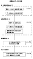
- FIG. 9 is a diagram showing a procedure for acquiring and comparing calibration detection data.
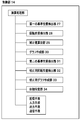
- FIG. 2 is a block diagram illustrating a configuration of a control unit 14 according to an embodiment of the present invention. It is a schematic diagram showing operation of an aligner of this embodiment.
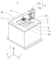
- FIG. 1 is a perspective view showing one embodiment of the aligner 1 of the present invention
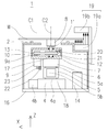
- FIG. 2 is a partial cross-sectional side view showing an outline of an internal structure with a frame portion of FIG. 1 as a cross section.
- the aligner 1 of the present embodiment detects the amount of shift of the position of the center point of the semiconductor wafer W and the position of a notch formed on the outer peripheral edge of the wafer such as the notch N and the orientation flat, and sets a predetermined predetermined value. For accurate positioning.
- the aligner 1 of the present embodiment includes an upper plate 3 on which a wafer temporary placing table 2 is erected, an X-axis drive mechanism 4 disposed below the upper plate 3, and a Y-axis driving mechanism 4 arranged at a position orthogonal to each other.
- An X-axis drive mechanism 5 (see FIG. 2), and the X-axis drive mechanism 4 and the Y-axis drive mechanism 5 move a lifting mechanism 6 disposed below the upper plate 3 in the XY plane. Can be done.
- the elevating table 7 of the elevating mechanism 6 is provided with a spindle 8 and a spindle drive motor 9 for rotating the semiconductor wafer W mounted on the spindle 8 in a horizontal plane.
- a drive pulley 10 is fixed to the output shaft 9a extending in the vertical direction concentrically with respect to the rotation center axis C1 of the output shaft 9a.
- a spindle shaft 11 is fixed to the lower part of the spindle 8 concentrically with respect to the spindle 8.
- a driven pulley 12 is coaxially fixed to the lower end of the spindle shaft 11 with respect to the spindle 8 and the spindle shaft 11. Fixed to.
- the spindle shaft 11 is rotatably supported by the lift 7 via a bearing 17, and the spindle 8, the spindle shaft 11, and the driven pulley 12 are integrally formed around a rotation center axis C2 extending in the vertical direction. It is configured to be rotatable.
- the drive pulley 10 and the driven pulley 12 are both toothed pulleys, and a toothed belt 13 (hereinafter, simply referred to as a “belt”) is looped between the two pulleys 10 and 12.
- a motor such as a stepping motor capable of precisely controlling the rotation angle of the output shaft 9a is used, and the operation of the spindle drive motor 9 is controlled by the control unit 14.
- the spindle 8 provided in the aligner 1 of the present embodiment is a wafer holding table that holds the wafer W horizontally, and a suction hole 15 for holding the wafer W placed horizontally on the spindle 8 by vacuum pressure.
- the manner in which the semiconductor wafer W is held on the spindle 8 is not limited to a method utilizing vacuum pressure, but may be a clamp-type holding mode for gripping the peripheral portion of the semiconductor wafer W or any other known holding mode. May be.
- the X-axis driving mechanism 4 is fixed to the lower surface plate 16, and a slide guide for guiding the moving element 4 a having the Y-axis driving mechanism 5 fixed on the upper surface in the X-axis direction, and the moving element is arranged in parallel with the sliding guide.
- the ball screw mechanism is screwed with the ball screw mechanism 4a, and an X-axis drive motor 4b that rotates a rotating shaft of the ball screw mechanism extending in the X-axis direction.
- the Y-axis drive mechanism 5 includes a slide guide that guides the moving element 5a on which the lifting mechanism 6 is mounted in the Y-axis direction, and a ball screw mechanism that is disposed parallel to the slide guide and that is screwed with the moving element 5a.
- the elevating mechanism 6 is a mechanism for vertically moving the elevating table 7 to which the spindle drive motor 9 is fixed, and a known slide guide for guiding the elevating table 7 in the Z-axis direction, and a parallel slide guide.
- a known air cylinder The air cylinder is connected to an air supply source (not shown) via a pipe. By turning on and off a solenoid valve (not shown) arranged in the middle of the pipe, the piston rod of the air cylinder expands and contracts. 7 is moved up and down in the vertical direction.
- the spindle 8 can be moved in the horizontal direction and the vertical direction by the spindle moving means 18 composed of the X-axis driving mechanism 4, the Y-axis driving mechanism 5, and the elevating mechanism 6.
- the motors 4b, 5b, 9 constituting the spindle moving means 18 are all stepping motors capable of precisely controlling the angle of the rotating shaft, and the operations of the motors 4b, 5b, 9 are controlled. It is controlled by the unit 14.
- An alignment sensor 19 is provided in the cutout portion 3 a of the upper plate 3 so as to sandwich the peripheral portion of the wafer W on the spindle 8 from above and below.
- This alignment sensor 19 has a line having a light projector 19a having a plurality of light projecting portions arranged linearly and a light receiving device 19b having a plurality of light receiving portions arranged linearly at positions corresponding to the light projecting portions.
- the sensor is a sensor that is opposed to the lower side and the upper side of the semiconductor wafer W, and the optical axis of the detection light emitted from the light projector 19a is perpendicular to the rotation direction of the semiconductor wafer W disposed on the spindle 8. It is arranged to become.
- the alignment sensor 19 detects the amount of eccentricity and the eccentric direction of the center of the semiconductor wafer W with respect to the rotation center axis C2 of the spindle 8 by the light receiver 19b in a state where the detection light emitted from the light projector 19a is blocked by the outer peripheral edge of the wafer W. It is measured by the detected value (the amount of received light).
- the detection value detected by the light receiver 19b is transmitted as an electric signal to the control unit 14, and is processed by the control unit 14.
- the semiconductor wafer W is often stored at a position deviated from a predetermined design position from the state of being stored in a storage container called a FOUP to the time of being transferred by a transfer robot. Therefore, the aligner 1 rotates the semiconductor wafer W held on the spindle 8 to detect the amount of eccentricity, and the control unit 14 sets the actual center point position of the semiconductor wafer W at a predetermined appropriate center position. Is temporarily placed on the wafer temporary placing table 2 so that the center position of the semiconductor wafer W is aligned with the center axis of the spindle 8 so that the spindle 8 is moved in the horizontal direction to change the semiconductor wafer W. . Further, the semiconductor wafer W is rotated in the horizontal direction so that the notch N is located at a predetermined rotation position.
- the aligner 1 of the present embodiment includes a drive mechanism for moving the spindle 8 in the horizontal direction and the vertical direction. After detecting the displacement of the semiconductor wafer W as described above, the spindle 8 changes the semiconductor wafer W.
- the present invention is not limited to this, and the spindle moving means 18 such as the X-axis driving mechanism 4, the Y-axis driving mechanism 5, and the elevating mechanism 6 for moving the spindle 8 in the horizontal direction.
- the present invention is sufficiently applicable to a single-axis control type aligner including only a mechanism for rotating the spindle 8 without the above-described configuration.
- the information of the detected positional shift amount and the angular shift from the center point of the semiconductor wafer W is transmitted to the wafer transfer robot, and when the wafer transfer robot holds the semiconductor wafer W with the wafer hand, the wafer hand is moved. After moving to the position where the amount of the positional deviation is canceled, the positional deviation of the semiconductor wafer W is corrected by holding the semiconductor wafer W.
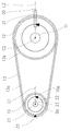
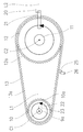
- FIG. 5 shows an example of a rotary drive mechanism of the aligner 1, and is a schematic diagram showing a drive pulley 10, a driven pulley 12, and a belt 13 provided in the aligner 1 of the present embodiment.
- External teeth 10a are formed at a predetermined pitch on the outer peripheral portion of the drive pulley 10 fixed to the output shaft 9a.
- External teeth 12b having the same shape as the external teeth 10a formed on the driving pulley 10 are formed at a predetermined pitch on the outer peripheral portion of the driven pulley 12 fixed to the spindle shaft 11.
- the belt 13 looped between the two pulleys 10 and 12 has internal teeth 13a meshing with external teeth 10a and 12a formed on the two pulleys 10 and 12, respectively.
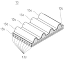
- FIG. 3 shows an example of a cross-sectional view illustrating an outline of the toothed belt 13 applicable to the present invention.
- the belt 13 included in the aligner 1 of the present embodiment is an annular timing belt, and at least a main body 13b on which the internal teeth 13a meshing with the external teeth 10a, 12a of the respective pulleys 10, 12, are formed. It is composed of a tooth cloth 13c attached to the surface of the main body 13b on which the internal teeth 13a are formed, and a tensile body 13d embedded in the main body 13b.
- the main body 13b is formed of an elastomer such as chloroprene rubber which is excellent in heat resistance and fatigue resistance and is relatively lightweight.
- the inside of the main body 13b formed of chloroprene rubber has a moving direction (peripheral) of the belt 13.
- a tension member 13d made of glass fiber, polyamide-based chemical fiber, or the like is embedded along the direction. Further, a tooth cloth 13c for preventing abrasion is attached to the surface of the main body 13b.
- the belt 13 is formed by pouring a material of the belt 13 such as chloroprene rubber into a space formed by two cylindrical dies having different diameters arranged concentrically.
- a mold arranged inside has a groove having a shape corresponding to the internal teeth 13 a of the belt 13.
- the inner mold is moved to the inner space of the outer cylindrical mold, Hot belt material is poured under pressure into the space between the inner and outer molds. Thereafter, after being cooled and removed from the mold, the belt material formed into a cylindrical shape is cut into a predetermined width along a circumferential direction to complete the belt 13.
- FIG. 4A and 4B are conceptual diagrams for explaining a manufacturing error of the internal teeth of the toothed belt.
- FIG. 4A illustrates a case where the belt is formed at a uniform pitch P
- FIG. 4B illustrates a case where the pitch is not uniform. Show.
- the belt 13 manufactured in the above process between the driving pulley 10 and the driven pulley 12 so as to have an appropriate tension, the transmission of the driving force without backlash can be easily performed.
- the internal teeth 13a due to shrinkage after molding and processing unevenness of the belt material, the internal teeth 13a are not molded to the same size, and the pitch of the internal teeth 13a becomes a dimension P1 larger than the specified dimension P. , Or a dimension P2 smaller than the prescribed dimension P.
- each of the internal teeth 13a becomes a size P4 smaller than the specified size P3 or a size P5 larger than the specified size P3, and a minute pitch error occurs.
- a minute pitch error of the belt 13 also occurs due to the non-uniformity of the elastic coefficient of the tensile member 13d made of a chemical fiber or the like. Due to the minute pitch error of the internal teeth 13a, the rotation of the driving pulley 10 may not be accurately transmitted to the driven pulley 12, and the rotation of the driving pulley 12 may cause uneven rotation of the driven pulley 12. In particular, when measuring the peripheral edge of the semiconductor wafer W, this deviation causes a trouble that the required alignment accuracy cannot be satisfied.
- the inventor of the present invention has found a method of eliminating the low positioning accuracy of the semiconductor wafer W due to a manufacturing error of the belt 13 with a simple configuration.
- the method discovered by the inventor is that the rotation unevenness of the driven pulley 12 caused by the belt 13 is detected by a sensor each time the driven pulley 12 makes one rotation, and the detected value is used to detect the driven pulley 20 with respect to a reference position (described later). , And corrects the position of the semiconductor wafer W by applying a correction value corresponding to the amount of position shift for each rotation of the driven pulley 12 at the time of alignment of the semiconductor wafer W. is there.
- the drive pulley 10 and the driven pulley 12 are set at a predetermined reduction ratio, and the belt 13 meshes with the external teeth 10a, 12a formed on the drive pulley 10 and the driven pulley 12. Is more effectively implemented when the number of internal teeth 13a is a prime number.
- the drive pulley 10 of the present embodiment has 30 external teeth 10a formed on the peripheral edge thereof at a predetermined pitch
- the driven pulley 12 has 60 external teeth 12a formed on the peripheral edge thereof at a predetermined pitch. It is formed with.
- the belt 13 wound around the driving pulley 10 and the driven pulley 12 is formed with 199 internal teeth 13a meshing with the external teeth 10a, 12a, which are prime numbers at a predetermined pitch.
- the drive pulley 10 is fixed to the output shaft 9a of the spindle drive motor 9 concentrically with respect to the rotation center axis C1.
- a stepping motor capable of precise angle control of the output shaft 9a is used.
- the resolution of the spindle drive motor 9 is, for example, a high precision capable of controlling an angle of 0.0225 ° per pulse. Is desirable.
- a transmitted light type origin sensor 22 is fixed below the spindle drive motor 9 via a bracket, and an origin dog 23 fixed to the output shaft 9a shields the optical axis of the origin sensor 22 from light.
- the control unit 14 can detect that the output shaft 9a of the spindle drive motor 9 and the drive pulley 10 are at the origin positions (see FIG. 5).
- a pulley detection sensor 20 for detecting the rotational position of the driven pulley 12 is disposed near the driven pulley 12, and a dog for blocking the optical axis of the pulley detection sensor 20 is provided on the upper surface of the driven pulley 12. 21 is fixed.
- the state where the driving pulley 22, the belt 13, and the driven pulley 12 are in the state of FIG. 5 will be described as a reference position. That is, the driving pulley 10 that moves in conjunction with the driving motor 9 is stopped at a position where the dog 23 of the driving motor 9 shields the origin sensor 22 from light, and the reference tooth G1 of the belt 13 is at the origin position at the left end of the driving pulley 10. It stops at O1, and the position which satisfies all the conditions that the front half of the dog 21 of the driven pulley 12 moves to the center of the pulley detection sensor 20 and is half-shielded (see the position in FIG. 6A).
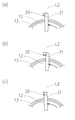
- FIGS. 6A, 6B, and 6C show an example of a pulley detection sensor 20 provided on the peripheral side of the driven pulley 12 and partially enlarged views for explaining various detection states thereof.
- the pulley detection sensor 20 is a transmitted light sensor in which a light receiver detects detection light emitted from the light emitter, and the light receiver detects light of a plurality of optical axes emitted from the light emitter and blocked by the dog 21. Is used to detect the rotational position of the driven pulley 12.
- the plurality of light projectors linearly arranged on the pulley detection sensor 20 are arranged such that the optical axis is perpendicular to a line L2 extending in the radial direction from the rotation center axis C2 of the driven pulley 12.
- the pulley detection sensor 20 detects the amount of light received by the light receiver, which varies depending on the state in which the detection light emitted from the projector is blocked by the dog 21, and the driven pulley 12 detects the amount (detected value) of the detected amount of received light. This is to measure an accurate rotation position after one rotation. For example, as shown in FIG. 6A, the position where the dog 21 shields the front half of the optical axes arranged in a line with the dog 21 is used as the reference position of the driven pulley 12 to determine the magnitude (detection value) of the amount of received light. It is measured and stored as the received light amount at the reference position.
- the driven pulley makes one rotation, if the driven pulley 12 stops slightly forward (toward the near side) from the reference position as shown in FIG.
- the optical axis (light amount) to be shielded becomes smaller than half, and the light amount larger than the light reception amount at the reference position is detected by the light receiver.
- 6C when the driven pulley 12 stops behind (excessively) the reference position, more than half of the optical axis (light amount) is shielded by the dog 21. The amount of light smaller than the amount of light received at is detected by the light receiver.
- the amount of deviation of the rotational position of the driven pulley 12 can be recognized based on the magnitude of the detected value. That is, when the detected value is large as shown in FIG. 6B, it is understood that the driven pulley has stopped before the reference position, and when the detected value is small as shown in FIG. Can be seen to have passed the reference position and stopped. It should be noted that it is possible to judge how much the vehicle has stopped before or after going too far based on the magnitude of the detected value (the magnitude of the amount of received light).
- the detection values detected by the pulley detection sensors 20 are transmitted to the control unit 14 as electric signals, and the control unit 14 calculates the position of the driven pulley 12 from the detected values and stores the calculated position in a storage unit provided in the control unit 14. .
- the “reference detection data” means that the driving pulley 10, the belt 13, and the driven pulley 12 are at the reference position, and then the driving pulley is driven to rotate the driven pulley 12 one rotation at a time. , While the drive pulley 10, the belt 13, and the driven pulley 12 all return to the reference position, the detection data for one cycle (a set of detection values), or is calculated based on this detection data. Correction value data (a set of correction values).
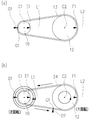
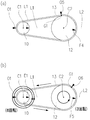
- FIG. 7A is a view showing a state where the driving pulley 10, the belt 13, and the driven pulley 12 are at the reference positions (the same position as in FIG. 5).
- the reference position of the driven pulley 20 is F1
- the position where the dog 21 of FIG. 6 (a) shields the pulley detection sensor 20 halfway and the state where the drive motor is at the origin position.
- the position of the drive pulley of E is described as E1.
- a line segment connecting the rotation centers C1 and E1 of the driving pulley is L1
- a line segment connecting the rotation centers C2 and F1 of the driven pulley is L2
- the corresponding position of the belt 13 stopped at the left end position O1 is set as the reference tooth G1.
- FIG. 7B shows the reference tooth G1 of the toothed belt 24 when the driving pulley is rotated twice and the driven pulley 12 is rotated once using an ideal toothed belt 24 having no manufacturing error. It is a figure which shows the position O2 and the rotational position of the driven pulley 12.
- the aligner 1 of the present embodiment described below has a drive pulley 10 having 30 external teeth 10a formed thereon, a driven pulley 12 having 60 external teeth 12a formed therein, and these external teeth 10a.
- the toothed belt is provided with 199 internal teeth 13a meshing with 12a.
- the toothed belt 24 moves to the position O2. Moves counterclockwise by 60 teeth.
- the driven pulley 12 also makes exactly one turn counterclockwise to return to the original reference position F1 indicated by the line segment L2, and no rotation error occurs.
- the reference tooth G1 which was at the origin position O1 at the time of the origin search of the spindle drive motor 9 is not driven by the driven pulley 12 until the driven pulley 12 rotates 199 times. Each time the belt 12 rotates once, it stops at 199 stop positions without overlapping on the orbit of the toothed belt 24. When the operation of the driven pulley 12 at the 199th rotation is completed, the reference tooth G1 of the toothed belt 24 returns to the same origin position O1 immediately after the origin search.
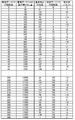
- FIG. 11 is a table showing the feed-out amount of the teeth for each rotation of the driven pulley 12 and the moving position of the toothed belt 24 reference tooth G1 accompanying the rotation.
- the stop position (until the driven pulley 12 makes 25 rotations) Position of the teeth).
- the reference tooth G1 which was initially at the position O1 moves to a position advanced by 60 teeth each time the driven pulley 12 makes one rotation, and stops at the same position while the driven pulley 12 makes 199 rotations. And stops at the same reference position only after 199 rotations.
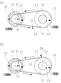
- FIGS. 8A and 8B are diagrams for explaining a rotation error in a case where the driven pulley 12 is rotated by rotating the driving pulley 10 using the belt 13 having a manufacturing error
- FIG. 8 shows a state in which the driving pulley 10 makes two rotations and the driven pulley makes one rotation
- FIG. 8B shows a state in which the driving pulley 10 further makes two rotations (four rotations from the origin search). I have.
- FIG. 8A and 8B are diagrams for explaining a rotation error in a case where the driven pulley 12 is rotated by rotating the driving pulley 10 using the belt 13 having a manufacturing error
- FIG. 8 shows a state in which the driving pulley 10 makes two rotations and the driven pulley makes one rotation
- FIG. 8B shows a state in which the driving pulley 10 further makes two rotations (four rotations from the origin search). I have.
- FIG. 8A and 8B are diagrams for explaining a rotation error in a case where the driven pulle
- the number of the internal teeth 13a of the belt 13 is 199, which is a prime number, the least common multiple of the number of the external teeth 12a of the driven pulley 12 and the number of the internal teeth of the belt 13 is 11940, and the number of the external teeth of the driving pulley 10 is Since the driving pulley 10 repeats the above-mentioned rotation operation 398 times, the driven pulley 12 rotates 199 times, and the belt 13 and the driven pulley 12 having a manufacturing error move to the original reference position shown in FIG. It returns to G1 and F1 and repeats the same operation with 199 times as one cycle. (Note that the drive pulley 10 fixed to the output shaft 9a of the spindle drive motor 9 always returns to the position E1 every one rotation without shifting.)
- the reference tooth G1 at the origin position O1 at the origin search of the spindle drive motor 9 is the position of the first internal tooth 13a of the belt 13
- the driven pulley 12 is rotated counterclockwise.
- the drive pulley 10 makes two rotations in the counterclockwise direction and makes the belt 13 advance 60 teeth counterclockwise in order to make one rotation
- the reference tooth G1 becomes the 61st position from the position of the first internal tooth 13a of the belt 13. It moves to the position of the internal teeth 13a.
- the reference tooth G1 is shifted from the position of the 61st internal tooth 13a of the belt 13 to the position of the 121st internal tooth 13a. Move up to.
- the belt 13 is sequentially fed out by 60 teeth, and the reference tooth G1 is shifted from the 61st tooth position to the 121st tooth position, the 181st tooth position, and the 42nd tooth. Move to the position of the tooth.
- the reference tooth G1 moves from the first tooth to the 61st tooth, from the 61st tooth to the 121nd tooth, from the 121th tooth to the 181st tooth, and so on.
- the tooth is sequentially moved to the position of the tooth 60 teeth ahead.
- the important point here is that the movement pattern of moving from a certain tooth position to the tooth 60 teeth ahead does not move until the 199th movement ends. That is, in the configuration of the aligner 1 of the present embodiment, the belt 13 has 199 movement patterns for the operation for rotating the driven pulley 12 once.
- the stop position after one rotation of the driven pulley 12 stops at a position shifted from the reference position F1 due to a manufacturing error of the belt 13, so that each time the movement of each of the 199 movement patterns is completed, the driven pulley 12 is stopped. Is detected by a pulley detection sensor, the correction value is calculated, and each movement pattern of the belt 13 is associated with the deviation amount and the correction value. The operation is performed so as to accurately move to the reference position F1.
- the change (displacement) in the position is all stored for each rotation as a change in the detection value of the pulley detection sensor 20.
- a difference between each detected value and a value detected by the pulley detection sensor 20 at the reference position F1 is obtained for each rotation from the reference position to 199 rotations, and a deviation amount of the driven pulley 12 for each rotation is calculated from the difference.
- the control unit 14 calculates and stores a correction value for each rotation speed of the drive pulley 10 from the difference. Further, the correction value may be calculated at the same time as the detection value of the pulley detection sensor is obtained, and only the correction value may be stored. It is desirable that the correction value is calculated as the number of control pulses of the drive motor.
- the correction value calculated here is used to correct the operation of the spindle drive motor 9 so that the rotation of the driven pulley is not shifted. Specifically, when the positioning of the semiconductor wafer W and the detection of the notch N are actually performed, the operation of the spindle drive motor 9 is performed by applying the stored correction value to the value detected by the alignment sensor 19. By performing the correction, the driven pulley 12 and the spindle 8, and furthermore, the semiconductor wafer W mounted on the spindle 8 can be accurately positioned.
- the amount of displacement detected 199 times is assumed to be a unique amount of displacement of each of the internal teeth 13a of the belt 13, and the driven pulley 12 generated by the displacement of each of the internal teeth 13a of the belt 13 is assumed.
- a correction value for the rotation unevenness is calculated and stored, and the correction value is applied according to the rotation angle of the spindle drive motor 9 to accurately position the semiconductor wafer W.
- the detection value of the pulley detection sensor 20 per rotation of the driven pulley 12 is periodically repeated with one cycle of 199 times in the case of the number of teeth of the driven pulley 12 and the belt 13 described above. Therefore, the difference between the value detected by the pulley detection sensor 20 for each rotation of the driven pulley 12 and the value detected at the reference position is plotted in synchronization with 199 phases in the orbital movement of the belt 13 with 199 cycles. Then, the correction value for uneven rotation of the driven pulley 12 is calculated by assuming the amount of rotation deviation of the driven pulley 12 with respect to the reference position of each phase.
- the rotation angle control of the spindle drive motor 9 is controlled by a pulse value by the control unit 14, this correction value is converted into the number of pulses of the pulse drive spindle drive motor 9.
- the control unit 14 determines the rotation angle information of the spindle drive motor 9 (the cumulative number of pulses of the stepping motor for each rotation for rotating the driven pulley 199 times: A correction of the shift amount due to the error) is also stored.
- the phase of the belt 13 refers to a rotational position of the belt 13 at a specific timing when the belt 13 performs a circulating operation (rotating operation) with one cycle being 199.
- the correction value for one cycle of the driven pulley 12 for the rotation unevenness of the driven pulley 12 obtained as described above is a correction amount starting from the reference position
- the reference value at which the correction value becomes zero is set as the reference value. It is assumed that the position is specified. However, if the power of the aligner is once turned off and then turned on again, or if the rotation angle information of the drive motor 9 is lost for some reason, the starting point is not known, and the rotation is applied by applying the stored correction value. Unevenness cannot be corrected. Therefore, the position (phase) of the driven pulley 12 in one cycle (199 positions) immediately after turning on the power is checked, and the actual positions of the driving pulley 10, the belt 13, and the driven pulley 12 are compared with the reference position.
- the first operation performed to achieve this synchronization is an origin search.
- the origin search the dock 22 of the drive motor 9 is detected.
- an operation substantially similar to the operation of acquiring the reference detection data at the time of shipment is performed.
- the operation for synchronizing after the origin search is almost the same as the operation for acquiring the reference detection data, and thus will be described with reference to FIGS. Note that the description will be made on the assumption that the positions of the driving pulley 10, the belt 13, and the driven pulley 12 are in the state of FIG. Since it is not known when the origin search is performed, the position of the belt 13 and the position of the driven pulley 12 immediately after the origin search are not always stopped at the reference positions set at the time of shipment. Assuming that the stop position of the reference tooth G1 and the driven pulley 12 immediately after the search for the origin is, for example, the reference tooth G1 is stopped at the position O3 in FIG.
- the drive pulley 10 rotates twice and the driven pulley 12 Is rotated once, the reference tooth G1 moves to the position O4. Then, every time the drive pulley 10 makes two rotations, the driven pulley 12 makes one rotation, and the reference tooth G1 sequentially moves to a position 60 tips ahead.
- a detection value for each rotation of the driven pulley 12 is acquired. Note that the driving pulley is not affected by the manufacturing error of the belt 13, and is the same as the case of the reference position.
- FIG. 18 is a block diagram illustrating a configuration of the control unit 14.
- the control unit 14 performs the rotation position detection operation of the present invention by performing a first reference position detection unit 27, a rotation position detection unit 28, a correction value calculation unit 29, a graph creation unit 30, a second reference position detection unit 31, A rotation position detecting unit 32 for calibration, a calibration graph creating unit 33, and a phase specifying unit 34 are provided.
- the control unit 14 includes an input unit that receives signals from various sensors and input devices, an output unit that transmits an operation control signal to a motor and the like, a storage unit that stores an operation program and various data, a host PC, and the like. Communication means for performing communication between the devices. These operation processes are performed by an arithmetic processing unit provided in the control unit 14 in accordance with an operation program stored in the storage unit in advance.
- FIG. 16 is a flowchart illustrating a procedure of a process of acquiring reference detection data.
- the drive pulley 10, the belt 13, and the driven pulley 12 (the number of teeth is 30, 199, and 60, respectively) of the present embodiment are used.
- the first reference position detecting section 27 operates the spindle drive motor 9 to perform an origin search, and the detection value of the pulley detection sensor 20 immediately after the origin search is used as the reference position of the driven pulley 12. (Reference value storage step: step 1).
- the rotation position detection unit 28 causes the driven pulley 12 to make one rotation by rotating the driving pulley 10 exactly two times, and stores the detection value of the pulley detection sensor 20 immediately after the driven pulley 12 makes one rotation. .
- the rotational position detecting unit 28 repeats the same two-turn operation of the driving pulley 10 and the detection by the pulley detecting sensor 20 until the driven pulley 12 makes 199 rotations, and stores all 199 detected values (detected value storing step). : Step 2).
- the detection operation is performed 199 times because 199 internal teeth 13a of the belt 13 are formed, but the present invention is not limited to this number. In short, the detection operation is performed until each of the driving pulley 10, the driven pulley 12, and the belt 13 returns to the same phase (the same position) as the reference position.
- the correction value calculation unit 29 calculates each of the 199 rotations of the driven pulley 12 from the detected value.
- a correction value corresponding to the detected value is calculated and stored (correction value calculation step: Step 3).
- the detection value at each rotational position of the driven pulley 12 of the pulley detection sensor 20 is compared with the origin reference data, and the difference between the detection values can be stored as a correction value. Further, the difference between the detected values can be converted into a step pulse amount of the spindle drive motor 9 and stored.
- the detection value of the pulley detection sensor 20 is obtained. Can be converted as the number of steps of the spindle drive motor 9. It is desirable that the rotational position detecting unit 28 store, as control information of the spindle drive motor 9, corrected rotational angle information of the spindle drive motor 9 for one cycle for each rotation of the driven pulley 12 for one cycle ( In order to rotate the driven pulley 12 for one cycle (199 rotations), the number of accumulated steps for each phase is stored).
- the detection data (detection value or correction value for one cycle) acquired as described above is rearranged so that the position numbers of the internal teeth 13a are in ascending order, and the reference axis G1 moves on the horizontal axis.
- the position number and the vertical axis of the determined internal teeth 13a are graphed as detection values or correction values. From this graph, an approximate straight line of the graph can be obtained and graphed (reference detection data acquisition step: Step 4).
- the position numbers of the internal teeth 13a on the horizontal axis are rearranged in ascending order.
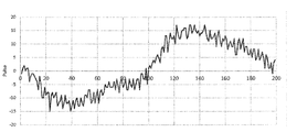
- the created graph has a waveform similar to a sine wave, and the inclination of the graph when an approximate straight line is obtained is easily specified.
- the belt 13 does not stop at the same tooth position where it stopped previously until the driven pulley 12 makes 199 rotations. Therefore, the number of rotations of the driven pulley 12 199 times and the belt 13 In association with the position (movement pattern) of each tooth 13a after each rotation operation, these 199 movement patterns are assumed to be manufacturing errors in the movement pattern rotated and moved to each internal tooth 13a of the belt 13, and each rotation
- the shift amount of the driven pulley 12 from the reference position F1 at this time is regarded as a correction value for each internal tooth 13a, in other words, a correction value for each phase (movement pattern) of the belt 13.
- the vertical axis represents each correction value calculated from a series of detection values detected by the operation of the reference value storage step and the detection value storage step
- the horizontal axis represents the position number of the internal teeth 13a of the belt 13.
- FIG. 9 is a graph showing this as an approximate straight line
- FIG. 14 is a graph.
- the detection value for each rotation detected by the above method or the correction value calculated from this detection value is the reference detection data. Since the number of pulses of the spindle rotation motor 9 per one rotation of the driven pulley 12 is known, the correction value (pulse) for the detection data of the semiconductor wafer W on the spindle 8 when the semiconductor wafer W is actually aligned. The semiconductor wafer W is accurately positioned by causing the spindle drive motor 9 to perform the rotation operation corresponding to (number).
- the positional relationship between the driving pulley 10, the driven pulley 12, and the belt 13 has returned to the reference position at the time when the reference detection data was obtained by simply performing the origin search of the spindle drive motor 9.
- As a countermeasure for example, by connecting an absolute type encoder to the output shaft 9a of the spindle drive motor 9, it is possible to store the rotational position when the power is turned off, but the absolute type encoder is expensive. Therefore, the manufacturing cost of the entire aligner 1 is greatly increased.
- the aligner 1 is operated in the following procedure, and a new reference position for specifying the rotational positions of the driving pulley 10, the driven pulley 12, and the belt 13 is set based on the data detected by the operation.
- a first reference position calibration process for performing In the calibration procedure first, the power of the aligner 1 is turned on, and the origin of the spindle drive motor 9 is searched. At this time, it is assumed that the position of the reference tooth G1 is at the position O3 in FIG. Next, the operation from the detection value storage step to the reference detection data acquisition step is performed. Here, the position of the reference tooth G1 is moved from the position O3 in FIG. 8A to O4 in FIG. 8B by rotating the driven pulley 12 once.
- the reference teeth G1 are sequentially stopped at the positions of the 199 internal teeth 13a.
- 199 pieces of detection data for all combinations of the positional relationship between the driving pulley 10, the driven pulley 12, and the belt 13 are obtained.
- the detected data is compared with the above-described reference detection data to identify the current rotational position (phase) of the driving pulley 10, the driven pulley 12, and the belt 13, and to determine a correction value that matches this phase. Apply as a correction value for the current rotational position.
- the collation between the newly detected calibration detection data and the reference detection data first detected from the reference position can be performed by individually comparing each of the 199 measurement values. However, a predetermined number of measured values of each graph of the original reference detection data and the newly measured calibration detection data are extracted, the slope of the graph is obtained, and the phase matching the slope of the original data is determined. Specifically, it is desirable that this position be the current rotational position. In addition, as a method of calculating a slope from each data, a method of obtaining a least square method or an approximate straight line or a regression line is desirable.
- the second reference position detection unit 31 and the calibration rotation position detection unit 32 are provided, and the rotation position at the time of the origin search is specified by collating with the reference detection data.
- the second reference position detection unit 31 performs an origin search of the spindle drive motor 9.
- the driving pulley 11 stops at the reference position E1
- the driven pulley 12 stops at the position F4 which is a position shifted from the reference position F1.
- the rotation position of the driven pulley 12 immediately after the origin search is detected by the pulley detection sensor 20, and the detected value is stored (calibration reference position storage step: Step 5).
- the calibration rotational position detection unit 32 further operates the spindle drive motor 9 to accurately rotate the drive pulley 10 six times in order to rotate the driven pulley 12 three times.
- the reference tooth G1 moves to the position O6 in FIG. 19B.
- the driven pulley stops at the position F5.
- the rotation position of the driven pulley 12 after the rotation operation of the driving pulley 10 is detected by the pulley detection sensor 20 and the detected value is stored.
- the calibration rotational position detection unit 32 repeats the above operation until a predetermined number, for example, 19 detection values can be obtained, and stores the detection values for each detection operation (calibration detection value storage step: Step 6). ).
- the calibration rotational position detector 32 When the detected value of the driven pulley 12 is stored, the calibration rotational position detector 32 also stores the rotation angle information of the spindle drive motor 9 at the time of the detection. Then, the calibration graph creating unit 33 creates a graph in which the vertical axis represents the detected value of the rotational position of the driven pulley 12 due to the rotational driving of the driving pulley 10, and the horizontal axis represents the temporary number assigned to the internal teeth 13 a of the belt 13. Then, an approximate straight line of the graph for every 19 rotations is obtained from this graph, the graph is formed, and the inclination of each part of the graph is obtained (calibration reference detection data acquisition step: Step 7).
- the phase specifying unit 34 calculates the approximate linear graph of the reference detection data created by the graph creation unit 30 in the reference detection data acquisition step and the calibration detection data created by the calibration graph creation unit 33 in the calibration reference detection data acquisition step. The inclination of each part of the approximate line graph is compared, and the position matching the reference detection data is determined as the current phase of the belt 13 (current position out of 199). (Phase specifying step: Step 8) Then, a correction value suitable for the current phase of the belt 13 is selected and applied as a correction value for the driven pulley 12.
- the number of teeth of the belt 13 included in the aligner 1 according to the embodiment of the present invention is 199
- the number of teeth of the driving pulley 10 is 30, and the number of teeth of the driven pulley 12 is 60. Is rotated six times, that is, every time the belt 13 is extended by 180 teeth, the driven pulley 12 rotates three times. Since the number of teeth 199 of the belt 13 is a prime number, the belt 13 having an error stops at a position (phase) different from the position where it stopped before during the rotation cycle of 199 times. The detection value corresponding to the displacement amount of the driven pulley 12 at a different position among the 199 positions can be obtained.
- acquisition of the calibration detection data may be such that the slope of the measured value can be calculated from the acquired detection data.
- the detection is performed 19 times every 180 teeth advance. However, when the detection is performed every 60 teeth advance, the data that can be acquired is within a certain number of times when the detection number is about 19 times. This is because the data is not evenly acquired among the 199 internal teeth 13a due to the bias toward the area of the teeth 13a. Further, instead of the detection every 180 teeth, the detection every 240 teeth may be performed. However, the advance of 240 teeth means that in the case of the belt 13 having 199 teeth, the belt 13 advances by 41 turns after the belt 13 makes one rotation. This means that the time for one rotation is wasted.
- the number of rotations of the driven pulley 12 is limited to a rotation number at which the belt 13 does not rotate more than one rotation.
- the important point here is that the detection is performed every time the number of teeth of the driven pulley 12 advances by a positive number.
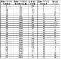
- FIG. 12 is a table showing the position of the internal teeth 13a of the belt 13 each time the driven pulley 12 advances by 180 teeth.
- the reference tooth G1 after the origin search is the internal tooth 13a of the 100th tooth of the belt 13. Shows when it is in position.
- the belt 13 advances by 180 teeth, and the same internal teeth 13a do not stop at the reference position O1 until the detection is completed 199 times.
- the rotational position of the driven pulley 12 for every three rotations and the position (phase) of the belt 13 are determined almost uniquely, and once the position (phase) of the belt 13 is determined, the position of the driven pulley 12 is specified.
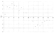
- FIG. 13 is a graph showing detection values of the detection data for calibration detected by rotating the driven pulley 12 by 180 teeth, that is, by rotating the driven pulley 12 three times.
- the position of the driven pulley 12 is detected 19 times, assuming that the position of the reference tooth G1 at the start of detection is the 100th tooth.
- the detected values are rearranged in ascending order with respect to the position of the reference tooth G1 of the belt 13, and the graph is plotted with the position of the internal tooth 13a to which the reference tooth G1 has moved on the horizontal axis and the detected value on the vertical axis.
- the scatter diagram may be displayed with the position of the reference tooth G1 as a horizontal axis without rearrangement in ascending order.
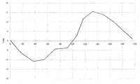
- FIG. 14 is a graph obtained by calculating an approximate straight line from the graph of the reference detection data in FIG.
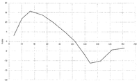
- the rotational position of the belt 13 is specified by matching the inclination of the graph of FIG. 14 with the inclination of the graph of the detection value of the detection data for calibration shown in FIG.
- the method of finding the approximate line used in the specifying method of the present invention may be a method of finding an approximate curve by polynomial approximation or moving average, or a method of finding a regression curve by the least squares method.
- FIG. 15 is a graph showing an approximate straight line calculated from the detection values of the calibration detection data shown in FIG.
- the horizontal axis of the graph shown in FIG. 14 is the position of the internal tooth 13a to which the reference tooth G1 has moved for each detection
- the horizontal axis of the graph shown in FIG. 15 is the position of the reference tooth G1 after the origin search. Assuming that the position is at the position of the 100th internal tooth 13a, this is the position of the internal tooth 13a to which the reference tooth G1 has moved for each detection.
- the vertical axis in FIGS. 14 and 15 represents the amount of displacement of the driven pulley 12 for each of the internal teeth 13a converted into a pulse. A comparison between the inclination of the graph of FIG.
- the control unit 14 compares the stored correction value with the current phase of the belt 13 to determine the correction value at the current phase of the belt 13 as the current correction value. Replace with a value.
- the calibration operation of the belt 13 is completed by the correction value replacing operation of the control unit 14. Since the unknown phase of the belt 13 has been determined, the driving pulley 10 is rotated and the positional relationship between the driving pulley 10, the driven pulley 12, and the belt 13 is detected by a method other than the method of replacing the correction value described above.
- the drive pulley 10 may be rotated a predetermined number of times until returning to the state when the data was acquired.
- the position of the driven pulley 12 is calculated by detecting a state in which the optical axis of the pulley detection sensor 20 is blocked by the dog 21 provided on the driven pulley 12 of the aligner 1.
- the present invention is not limited to this.
- the present invention is sufficiently applicable to an aligner 1 having no means for detecting the rotational position of the driven pulley 12.
- a correction method in the aligner 1 having no means for detecting the position of the driven pulley 12 will be described.
- the aligner 1 of the present embodiment the semiconductor wafer W and the alignment sensor 19 are used as means for detecting the rotational position of the driven pulley 12.
- the aligner 1 also has the same number of external teeth as the drive pulley 10, the outer pulley 12 as the driven pulley 12, and the internal teeth of the belt 13, similarly to the first embodiment. The number is described as 199.
- the spindle drive motor 9 of the aligner 1 of the present embodiment is operated to search for the origin.
- the semiconductor wafer W is placed using a jig or the like so that the rotation center axis C2 of the spindle 8 and the center position of the semiconductor wafer W are aligned with each other.
- the wafer W is fixed to the spindle 8 (fixing step).
- the spindle drive motor 9 is operated, the notch N of the semiconductor wafer W is detected by the alignment sensor 19, and the detected value is stored in the control unit 14 as a reference position detection value (second reference value storage step).
- a predetermined operation for rotating the driven pulley 12 once by the spindle driving motor 9 is performed, and the operation of detecting the notch N of the semiconductor wafer W by the alignment sensor 19 is performed by the driving pulley 10, the driven pulley 12, 13 is repeated until it returns to the respective reference position, and the detection value of the alignment sensor 19 every time the driven pulley 12 makes one rotation and the rotation angle information of the spindle drive motor 9 when the alignment sensor 19 detects the notch N (Pulse) is stored in the control unit 14 (second detection value storage step).
- a correction value for correcting the displacement of the driven pulley 12 every one rotation is calculated from the detection value of the alignment sensor 19 (second correction value calculation step). Then, the notch detection value for 199 rotations of the semiconductor wafer W corresponding to the rotation position for 199 rotations of the driven pulley 12 due to the rotation driving of the driving pulley 10 is allocated to the internal teeth 13 a formed on the belt 13 on the vertical axis. Then, a graph having the numbers on the horizontal axis is created, and an approximate straight line for each predetermined range of the graph and its slope are calculated to obtain reference detection data. (Second reference detection data acquisition step).
- the origin search is performed once, and after the origin position return operation of the spindle drive motor 9 is performed, the spindle drive motor 9 is stopped while the semiconductor wafer W is held on the spindle 8.
- the notch N of the semiconductor wafer W is detected by the alignment sensor 19, and the detected value of the alignment sensor 19 and the rotation angle information (pulse) of the spindle drive motor 9 when the alignment sensor 19 detects the notch N are controlled. It is stored in the section 14 (second calibration reference position storage step).
- the spindle drive motor 9 is operated, the drive pulley 10 is rotated exactly six times in order to rotate the semiconductor wafer W on the spindle 8 three times, and the semiconductor wafer W after the rotation of the drive pulley 10 is rotated.
- the notch N is detected by the alignment sensor 19, and the detected value is stored in the control unit 14.
- step 15 the operation in step 15 is repeated until a predetermined number of detected values can be obtained, and the detected values for each of the detected operations are stored in the control unit 14 (second calibration detected value storing step). Then, a graph is created in which the vertical axis represents the detected value of the notch N of the semiconductor wafer W due to the rotational driving of the driving pulley 10, and the horizontal axis represents the position of the internal tooth 13a to which the reference tooth G1 has moved for each detection. An approximate straight line of a graph for each predetermined rotation is obtained and graphed (second calibration reference detection data acquisition step).
- the slope of the approximate straight line graph of the reference detection data created in the second reference detection data acquisition step and the approximation straight line graph of the calibration detection data created in the second calibration reference detection data acquisition step are compared to determine the current belt. Thirteen phases are specified (second phase specifying step). Then, a correction value suitable for the current phase of the belt 13 is selected and applied as a correction value for the driven pulley 12. According to the above procedure, a precise correction value at the time of wafer alignment can be applied to the aligner 1 having no pulley detection sensor 20.
- a mark 25 is provided on the belt 13 provided in the aligner 1, a belt detection sensor 26 for detecting the mark 25 is provided near the belt 13, and a belt 13 is provided.
- the driving pulley 10, the driven pulley 12, and the belt 13 can be returned to the reference positions.
- the belt detection sensor 26 may be a transmitted light sensor
- the mark 25 may be a projection that blocks the optical axis. May be a reflection type sensor, and the mark 25 may reflect this optical axis.
- it is desirable that the mark 25 has a size smaller than the size P3 of the prescribed internal teeth 13a.
- the spindle drive motor 9 After the spindle drive motor 9 returns to the origin, the spindle drive motor 9 is operated to continuously rotate the drive pulley 10, and all of the pulley detection sensor 20, the origin sensor 22, and the belt detection sensor 26 react. At this point, it can be recognized that it has returned to the reference position.
- the present invention is not limited to the above embodiments, and changes and the like can be made without departing from the gist of the present invention. is there.
- the number of the internal teeth 13a of the belt 13 has been described as being twice as large as 199, the present invention is not limited to this, and may be a prime number such as 163 or 223. It is.
- the number of the external teeth 10a, 12a of the driving pulley 10 and the driven pulley 12 has been described as 30, 60, respectively.
- the present invention is not limited to this, and the rotation ratio of the driving pulley 10 and the driven pulley 12 is a positive number. Even if not, the present invention is sufficiently applicable.
Landscapes
- Container, Conveyance, Adherence, Positioning, Of Wafer (AREA)
- Engineering & Computer Science (AREA)
- Robotics (AREA)
- Devices For Conveying Motion By Means Of Endless Flexible Members (AREA)
- Apparatus For Radiation Diagnosis (AREA)
Abstract
Description
すなわち、本実施形態のアライナ1の構成では、従動プーリ12を1回転させるための動作について、ベルト13には199通りの移動パターンが存在するということである。そして、従動プーリ12の1回転したあとの停止位置は、ベルト13の製造誤差により、基準位置F1からずれた位置に停止するので、199通りの各移動パターンの移動が終了する度に従動プーリ12の1回転ごとのずれ量をプーリ検出センサで検出して、その補正値を算出し、ベルト13の各移動パターンとずれ量および補正値を関連付けて、どの移動パターンであっても従動プーリ12が基準位置F1に正確に移動するように動作させるのである。
そのため、電源投入直後等における従動プーリ12の位置が1周期(199個の位置)のどの位置(位相)にいるのかを調べて、実際の駆動プーリ10、ベルト13、従動プーリ12の位置と基準検出データに基づいて作成した補正値と、同期をとる必要がある。この同期をとるために行う最初の動作が原点サーチである。原点サーチでは、駆動モータ9のドク22を検知する。原点サーチにより、ドク22を検知した位置を仮基準位置として、出荷時の基準検出データ取得の動作とほぼ同様の動作を行う。
原点サーチはどのタイミングで実行されるかわからないため、原点サーチ直後のベルト13の位置、従動プーリ12の位置は、出荷時に設定したときの基準位置に停止するとは限らない。原点サーチ直後の基準歯G1と従動プーリ12の停止位置が、例えば基準歯G1が図8(a)のO3の位置に停止していたとすると、次に駆動プーリ10が2回転して従動プーリ12を1回転させると、基準歯G1はO4の位置に移動する。そして駆動プーリ10が2回転するごとに従動プーリ12は1回転し、基準歯G1は順次60歯先の位置に移動する。この電源再投入後の原点サーチをした後の基準歯G1の位置O3を仮基準として、従動プーリ12の1回転毎の検出値を取得する。なお、駆動プーリはベルト13の製造誤差の影響を受けないので、基準位置の場合と同じである。
具体的な同期方法については、以下に説明する。なお、以下の説明では、この仮基準データを取得する処理を第二の基準位置検出、同期をとる処理を校正回転位置検出と称する。
なお、回転位置検出部28は、スピンドル駆動モータ9の制御情報として、従動プーリ12の1回転毎の、スピンドル駆動モータ9の補正後の回転角度情報を1周期分記憶しておくことが望ましい(従動プーリ12を1周期分回転(199回転)させるために、各位相毎の累積ステップ数を記憶する)。
なお、以下の説明においては、補正値をグラフ化する例について説明する。
2 ウエハ仮置き台
3 上面プレート
8 スピンドル
9 スピンドル駆動モータ
10 駆動プーリ
12 従動プーリ
13 ベルト
19 アライメントセンサ
20 プーリ検出センサ
21 ドグ
G1 基準歯
O1~O4 基準歯の移動位置
Claims (20)
- 回転角度制御可能なモータと、
前記モータによって駆動される外歯を備える駆動プーリと、
前記駆動プーリに対して所定の回転比で構成される外歯を備える従動プーリと、
前記駆動プーリと前記従動プーリに歯合して、前記駆動プーリと前記従動プーリとの間に掛け廻される歯付きベルトと、
前記従動プーリに同心軸状に固定され、半導体ウエハを固定する固定手段を有するスピンドルと、
前記スピンドル上に固定された半導体ウエハの周縁を検出するアライメントセンサと、
投光部と受光部を備えており、前記モータが前記駆動プーリを駆動して前記従動プーリを1回転させたときの該従動プーリの回転位置を前記受光部による受光量として検出し、その大きさを検出値として出力するプーリ検出センサと、
入出力部と演算部と記憶部とを備えており前記各部の動作を制御する制御部と、
を備えるアライナにおいて、前記制御部により前記歯付きベルトの製造誤差に起因する前記従動プーリの回転方向の位置ずれを補正する補正値を算出する補正値算出方法であって、
前記駆動プーリと前記従動プーリと前記歯付きベルトのそれぞれが所定の基準位置にあるときの前記従動プーリの回転位置を前記プーリ検出センサで検出して、この検出値を基準値として前記制御部に記憶させる基準値記憶ステップと、
前記モータに前記従動プーリを1回転させるための所定の回転動作を行わせたときの前記プーリ検出センサの検出値を、前記駆動プーリ、前記従動プーリ及び前記歯付きベルトの全てが前記基準位置に復帰するまで実行させて、前記従動プーリの1回転毎に前記制御部に記憶させる検出値記憶ステップと、
前記制御部に記憶させた前記検出値の変化量から、前記制御部に前記従動プーリの1回転毎の回転位置のずれ量を補正する補正値を算出する補正値算出ステップと、
を備えることを特徴とするアライナの補正値算出方法。 - 前記従動プーリは、前記駆動プーリの整数倍の外歯を備え、前記歯付きベルトは素数の内歯を備えることを特徴とする請求項1に記載のアライナの補正値算出方法。
- 前記補正値は、前記モータの回転角度を制御する制御量であることを特徴とする請求項2に記載のアライナの補正値算出方法。
- 前記基準値記憶ステップ及び前記検出値記憶ステップにより検出した前記検出値、または前記補正値算出ステップにより算出した補正値に基づいて、前記検出値または前記補正値を縦軸とし、前記歯付きベルトに形成された各内歯に割り当てられた番号を横軸とするグラフを作成し、該グラフ所定の範囲毎の近似直線とその傾きを算出して基準検出データを取得する基準検出データ取得ステップを含むことを特徴とする請求項1から3のいずれか1項に記載のアライナの値算出方法。
- さらに、
回転角度情報を喪失した前記モータを作動させて原点サーチを行い、前記原点サーチ動作後の前記従動プーリの回転位置を前記プーリ検出センサで検出して、検出値を前記制御部に記憶する校正基準位置記憶ステップと、
前記モータに前記従動プーリを所定の回数回転させるための回転動作を行わせた後、前記従動プーリの回転位置を前記プーリ検出センサで検出する動作を所定の回数繰り返し行い、前記回転動作ごとの前記プーリ検出センサが検出する校正検出値を前記制御部に記憶する校正検出値記憶ステップと、
前記制御部に記憶した前記校正検出値のグラフを作成し、前記グラフの所定の検出範囲ごとの傾きを算出する校正基準検出データ取得ステップと、
前記基準検出データ取得ステップで作成された前記グラフと前記校正基準検出データ取得ステップで作成した前記グラフとを比較して、前記駆動プーリと前記従動プーリと前記歯付きベルトの位相を特定する位相特定ステップと、
を含むことを特徴とする請求項4に記載のアライナの補正値算出方法。 - 回転角度制御可能なモータと、
前記モータによって駆動される駆動プーリと、
前記駆動プーリに対して所定の回転比で構成される従動プーリと、
前記駆動プーリと前記従動プーリに歯合して、前記駆動プーリと前記従動プーリとの間に掛け廻される歯付きベルトと、
前記従動プーリに同心軸状に固定され、半導体ウエハを固定する固定手段を有するスピンドルと、
前記スピンドル上に固定された半導体ウエハの周縁を検出するアライメントセンサと、
制御部と、
を備えるアライナにおいて、前記歯付きベルトの製造誤差に起因する前記従動プーリの回転方向の位置ずれを補正する補正値を算出する補正値算出方法であって、
前記半導体ウエハの中心位置が前記スピンドルの回転中心軸と合致するように前記半導体ウエハを前記スピンドル上の所定の位置に固定する固定ステップと、
前記モータを作動させて、前記半導体ウエハを回転させて前記半導体ウエハのノッチの位置を前記アライメントセンサで検出して、この検出値を基準位置検出値として前記制御部に記憶させる第2基準値記憶ステップと、
前記モータに前記従動プーリを1回転させるための所定の回転動作を行わせた後、前記半導体ウエハのノッチ位置を前記アライメントセンサで検出する検出動作を、前記駆動プーリと前記従動プーリと前記歯付きベルトの全てがそれぞれの前記基準位置に復帰するまで繰り返して、1回転毎の検出値をすべて記憶する第2検出値記憶ステップと、
前記制御部に記憶させた前記基準位置検出値と1回転毎の前記検出値から、前記半導体ウエハの1回転する毎の前記位置ずれを補正する補正値を算出する第2補正値算出ステップと
を含むことを特徴とするアライナの補正値算出方法。 - 前記第2検出値記憶ステップにより検出した前記検出値に基づいて、前記検出値または前記補正値を縦軸とし、前記歯付きベルトに形成された各内歯に割り当てられた番号を横軸とする前記検出値または前記補正値のグラフを作成し、該グラフの所定の範囲毎の近似曲線とその傾きを算出して基準検出データを取得する第2基準検出データ取得ステップを含むことを特徴とする請求項6に記載のアライナの補正値算出方法。
- さらに、
回転角度情報を喪失した前記モータを作動させて原点サーチを行い、前記原点サーチ動作後に前記半導体ウエハのノッチを前記アライメントセンサで検出して、前記ノッチの検出値を前記制御部に記憶させる第2校正基準位置記憶ステップと、
前記モータを、前記従動プーリを所定の回数回転させるための回転動作を行わせた後、前記半導体ウエハの前記ノッチ位置を前記アライメントセンサで検出する動作を所定の回数繰り返し行い、前記回転動作ごとの前記アライメントセンサが検出する検出値を前記制御部に記憶させる第2校正検出値記憶ステップと、
前記制御部に記憶させた前記検出値のグラフを作成し、前記グラフの所定の検出範囲ごとの傾きを算出する第2校正基準検出データ取得ステップと、
前記第2基準検出データ取得ステップで作成された前記グラフと、前記第2校正基準検出データ取得ステップで作成した前記グラフとを比較して、前記駆動プーリと前記従動プーリと前記歯付きベルトの位相を特定する第2位相特定ステップと、
を含むことを特徴とする請求項7に記載のアライナの補正値算出方法。 - 前記歯付きベルトに形成される内歯の数と前記駆動プーリに形成される外歯の数と前記従動プーリに形成される外歯の数には、1以外の公約数が存在しないことを特徴とする請求項6から8のいずれか1項に記載のアライナの補正値算出方法。
- 前記歯付きベルトに形成される内歯の数が素数であることを特徴とする請求項6から9のいずれか1項に記載のアライナの補正値算出方法。
- 前記従動プーリに形成される外歯の数は、前記駆動プーリに形成される外歯の数の整数倍であることを特徴とする請求項6から8のいずれか1項に記載のアライナの補正値算出方法。
- 回転角度制御可能なモータと、
前記モータによって駆動される駆動プーリと、
前記駆動プーリに対して所定の回転比で構成される従動プーリと、
前記駆動プーリと前記従動プーリに歯合して、前記駆動プーリと前記従動プーリとの間に掛け廻される歯付きベルトと、
前記従動プーリに同心軸状に固定され、半導体ウエハを固定する固定手段を有するスピンドルと、
前記スピンドル上に固定された半導体ウエハの周縁を検出するアライメントセンサと、
前記従動プーリの回転位置を検出するプーリ検出センサと、
制御部と、を備えるアライナであって、
前記歯付きベルトの製造誤差に起因する前記従動プーリの回転方向の位置ずれを補正する補正値を算出するにあたって、前記制御部は、
前記駆動プーリと前記従動プーリと前記歯付きベルトのそれぞれが基準位置にある時の前記従動プーリの回転位置を前記プーリ検出センサで検出して、この基準位置検出値を記憶する第一の基準位置検出部と、
前記モータに前記従動プーリを1回転させるための所定の回転動作を行わせた後、前記従動プーリの回転位置を前記プーリ検出センサで検出する動作を前記駆動プーリと前記従動プーリと前記歯付きベルトの全てがそれぞれの前記基準位置に復帰するまで実行して、前記従動プーリの1回転毎の回転位置検出値を記憶する回転位置検出部と、
前記基準位置検出値と前記回転位置検出値とから、前記従動プーリの1回転する毎の前記位置ずれを補正する補正値を算出する補正値算出部と、
を備えることを特徴とするアライナ。 - 前記制御部は、算出された前記検出値に基づいて、前記検出値または前記補正値を縦軸とし、前記歯付きベルトに形成された各内歯に割り当てられた番号を横軸とするグラフを作成し、該グラフの所定の検出範囲毎の近似直線とその傾きを算出するグラフ作成部をさらに備えることを特徴とする請求項12に記載のアライナ。
- 前記制御部は、回転角度情報を喪失した前記モータを作動させて原点サーチを行わせ、 前記駆動プーリが基準位置に復帰した時の前記従動プーリの回転位置を前記プーリ検出センサで検出して、検出値を記憶する第二の基準位置検出部と、
前記モータに前記従動プーリを所定の回数回転させるための回転動作を所定の回数繰り返し行わせた後、前記従動プーリの回転位置を前記プーリ検出センサで検出して、この検出値を記憶する校正用回転位置検出部と、
前記校正用回転位置検出部が検出した前記検出値のグラフを作成する校正用グラフ作成部と、前記グラフの所定の検出範囲ごとの傾きを算出し、
前記グラフ作成部によって作成された前記グラフと前記校正用グラフ作成部によって作成した前記グラフとを比較して、前記駆動プーリと前記従動プーリと前記歯付きベルトの位相を特定する位相特定部とを備えることを特徴とする請求項13に記載のアライナ。 - 前記歯付きベルトに形成される内歯の数と前記駆動プーリに形成される外歯の数と前記従動プーリに形成される外歯の数には、1以外の公約数が存在しないことを特徴とする、請求項12から14のいずれか1項に記載のアライナ。
- 前記歯付きベルトに形成される内歯の数が素数であることを特徴とする請求項12から14のいずれか1項に記載のアライナ。
- 前記従動プーリに形成される外歯の数は、前記駆動プーリに形成される外歯の数の整数倍であることを特徴とする請求項12から14のいずれか1項に記載のアライナ。
- 回転角度制御可能なモータと、
前記モータによって駆動される駆動プーリと、
前記駆動プーリに対して所定の回転比n(nは整数)で構成される従動プーリと、
前記駆動プーリと前記従動プーリに歯合して、前記駆動プーリと前記従動プーリとの間に掛け廻される歯付きベルトと、
前記従動プーリに同心軸状に固定され、半導体ウエハを固定する固定手段を有するスピンドルと、
前記スピンドル上に固定された半導体ウエハの周縁を検出するアライメントセンサと、
前記従動プーリの回転位置を検出するプーリ検出センサと、
制御部と、
を備えるアライナにおいて、
前記歯付きベルトの製造誤差に起因する前記従動プーリの回転方向の位置ずれを補正する補正値算出方法であって、
前記制御部は、
前記モータによって前記駆動プーリをn回回転動作させて、その回転動作ごとに前記プーリ検出センサで前記従動プーリの回転位置を検出し、
前記従動プーリの前記回転動作ごとに前記プーリ検出センサで前記従動プーリの回転位置を検出する動作を、前記歯付きベルトに形成された内歯の数だけ実行して、前記プーリ検出センサが検出した検出値から、前記従動プーリの各回転に対応する各前記検出値を前記従動プーリの前記回転ごとの補正値を前記歯付きベルトの各回転位置に対応する補正値として算出するアライナの補正値算出方法。 - 前記各検出値に基づいて、前記検出値または前記補正値を縦軸とし、前記歯付きベルトに形成された各内歯に割り当てられた番号を横軸とするグラフを作成し、該グラフの所定の範囲毎の近似曲線とその傾きを算出して基準検出データを取得することを特徴とする請求項18に記載のアライナの補正値算出方法。
- 回転角度情報を喪失した場合に、
前記モータを作動させて原点サーチを行い、前記原点サーチ動作後の前記従動プーリの回転位置を前記プーリ検出センサで検出し、次に、前記モータに前記従動プーリを所定の回数回転させるための回転動作を行わせた後、前記従動プーリの回転位置を前記プーリ検出センサで検出して、前記原点サーチ後の前記検出値のグラフを作成して該前記グラフの所定の検出範囲ごとの傾きを算出し、
前記原点サーチ後のグラフの傾きと、前記基準検出データのグラフの傾きと比較して、前記駆動プーリと前記従動プーリと前記歯付きベルトの位相を特定する校正用検出データを取得することを特徴とする請求項19に記載のアライナの補正値算出方法。
Priority Applications (5)
| Application Number | Priority Date | Filing Date | Title |
|---|---|---|---|
| KR1020207036551A KR102706849B1 (ko) | 2018-06-22 | 2019-06-20 | 얼라이너 및 얼라이너의 보정값 산출 방법 |
| JP2020525797A JP7335878B2 (ja) | 2018-06-22 | 2019-06-20 | アライナ及びアライナの補正値算出方法 |
| EP19822985.8A EP3813100B1 (en) | 2018-06-22 | 2019-06-20 | Aligner and correction value calculation method for aligner |
| CN201980041840.3A CN112313789B (zh) | 2018-06-22 | 2019-06-20 | 对准器以及对准器的修正值计算方法 |
| US17/128,199 US12020969B2 (en) | 2018-06-22 | 2020-12-21 | Aligner and correction value calculation method for aligner |
Applications Claiming Priority (2)
| Application Number | Priority Date | Filing Date | Title |
|---|---|---|---|
| JP2018-118857 | 2018-06-22 | ||
| JP2018118857 | 2018-06-22 |
Related Child Applications (1)
| Application Number | Title | Priority Date | Filing Date |
|---|---|---|---|
| US17/128,199 Continuation US12020969B2 (en) | 2018-06-22 | 2020-12-21 | Aligner and correction value calculation method for aligner |
Publications (1)
| Publication Number | Publication Date |
|---|---|
| WO2019244982A1 true WO2019244982A1 (ja) | 2019-12-26 |
Family
ID=68982697
Family Applications (1)
| Application Number | Title | Priority Date | Filing Date |
|---|---|---|---|
| PCT/JP2019/024519 Ceased WO2019244982A1 (ja) | 2018-06-22 | 2019-06-20 | アライナ及びアライナの補正値算出方法 |
Country Status (7)
| Country | Link |
|---|---|
| US (1) | US12020969B2 (ja) |
| EP (1) | EP3813100B1 (ja) |
| JP (1) | JP7335878B2 (ja) |
| KR (1) | KR102706849B1 (ja) |
| CN (1) | CN112313789B (ja) |
| TW (1) | TWI780339B (ja) |
| WO (1) | WO2019244982A1 (ja) |
Cited By (4)
| Publication number | Priority date | Publication date | Assignee | Title |
|---|---|---|---|---|
| CN111540695A (zh) * | 2020-05-07 | 2020-08-14 | 北京北方华创微电子装备有限公司 | 旋转组件和半导体工艺设备 |
| JP2020126927A (ja) * | 2019-02-04 | 2020-08-20 | 東京エレクトロン株式会社 | 半導体製造装置およびステージの回転制御方法 |
| JP2022110551A (ja) * | 2021-01-18 | 2022-07-29 | ファスフォードテクノロジ株式会社 | ダイボンディング装置および半導体装置の製造方法 |
| JP2024161873A (ja) * | 2023-05-08 | 2024-11-20 | ウォニク アイピーエス カンパニー リミテッド | 基板処理装置 |
Families Citing this family (4)
| Publication number | Priority date | Publication date | Assignee | Title |
|---|---|---|---|---|
| EP3885698B1 (en) * | 2020-01-31 | 2022-09-28 | NSK Ltd. | Calibration method for rotation angle calculation device, calibration device for rotation angle calculation device, rotation angle calculation device, motor control equipment, electric actuator product, and electric power steering apparatus |
| JP2022048506A (ja) * | 2020-09-15 | 2022-03-28 | 株式会社ダイヘン | アライナ装置 |
| CN113587646B (zh) * | 2021-06-18 | 2023-11-03 | 浙江天鹰机车有限公司 | 防转动误差的智能制造用实验室烧结装置 |
| TWM661429U (zh) * | 2024-08-05 | 2024-10-01 | 三和技研股份有限公司 | 晶圓定位裝置 |
Citations (5)
| Publication number | Priority date | Publication date | Assignee | Title |
|---|---|---|---|---|
| JPH06249306A (ja) * | 1993-02-27 | 1994-09-06 | Star Micronics Co Ltd | プーリ装置 |
| JP2002164419A (ja) | 2000-11-29 | 2002-06-07 | Assist Japan Kk | アライナー |
| JP2008002664A (ja) * | 2006-06-26 | 2008-01-10 | Fujitsu Ltd | トルク伝達装置 |
| JP2009109713A (ja) * | 2007-10-30 | 2009-05-21 | Ricoh Co Ltd | 伝動装置及び画像形成装置 |
| JP2013157462A (ja) | 2012-01-30 | 2013-08-15 | Yaskawa Electric Corp | 伝達機構、基板位置決め装置およびロボット |
Family Cites Families (14)
| Publication number | Priority date | Publication date | Assignee | Title |
|---|---|---|---|---|
| JPS56117104A (en) * | 1980-02-20 | 1981-09-14 | Bando Chem Ind Ltd | Measuring device for cummulative and pitch error of toothed belt |
| JPH0810121B2 (ja) * | 1986-08-27 | 1996-01-31 | 株式会社共和電業 | ひずみ測定器における較正装置 |
| JPS63292014A (ja) * | 1987-05-25 | 1988-11-29 | Matsushita Electric Ind Co Ltd | 検査装置 |
| US5452521A (en) * | 1994-03-09 | 1995-09-26 | Niewmierzycki; Leszek | Workpiece alignment structure and method |
| JP3910427B2 (ja) * | 2001-11-30 | 2007-04-25 | 本田技研工業株式会社 | 歯車研削機の初期位相合わせ方法 |
| JP4201564B2 (ja) * | 2001-12-03 | 2008-12-24 | 日東電工株式会社 | 半導体ウエハ搬送方法およびこれを用いた半導体ウエハ搬送装置 |
| JP4408351B2 (ja) * | 2002-10-24 | 2010-02-03 | リンテック株式会社 | アライメント装置 |
| JP2007137535A (ja) | 2005-11-15 | 2007-06-07 | Ricoh Co Ltd | ベルト駆動制御装置及びこれを備えた画像形成装置 |
| JP2008082664A (ja) | 2006-09-28 | 2008-04-10 | Daikin Ind Ltd | 温水循環暖房システム |
| JP2008270474A (ja) * | 2007-04-19 | 2008-11-06 | Yaskawa Electric Corp | プリアライナー装置、それを備えた搬送システム及び半導体製造装置 |
| JP2010052095A (ja) * | 2008-08-28 | 2010-03-11 | Star Micronics Co Ltd | 数値制御旋盤 |
| CN101905805A (zh) | 2010-07-30 | 2010-12-08 | 上海宏力半导体制造有限公司 | 传动带缺陷检测装置及检测方法 |
| JP6263017B2 (ja) * | 2013-12-16 | 2018-01-17 | 川崎重工業株式会社 | 基板位置合わせ装置及び基板位置合わせ装置の制御方法 |
| US9349629B2 (en) * | 2014-01-23 | 2016-05-24 | Lam Research Corporation | Touch auto-calibration of process modules |
-
2019
- 2019-06-20 EP EP19822985.8A patent/EP3813100B1/en active Active
- 2019-06-20 WO PCT/JP2019/024519 patent/WO2019244982A1/ja not_active Ceased
- 2019-06-20 CN CN201980041840.3A patent/CN112313789B/zh active Active
- 2019-06-20 JP JP2020525797A patent/JP7335878B2/ja active Active
- 2019-06-20 KR KR1020207036551A patent/KR102706849B1/ko active Active
- 2019-06-21 TW TW108121715A patent/TWI780339B/zh active
-
2020
- 2020-12-21 US US17/128,199 patent/US12020969B2/en active Active
Patent Citations (5)
| Publication number | Priority date | Publication date | Assignee | Title |
|---|---|---|---|---|
| JPH06249306A (ja) * | 1993-02-27 | 1994-09-06 | Star Micronics Co Ltd | プーリ装置 |
| JP2002164419A (ja) | 2000-11-29 | 2002-06-07 | Assist Japan Kk | アライナー |
| JP2008002664A (ja) * | 2006-06-26 | 2008-01-10 | Fujitsu Ltd | トルク伝達装置 |
| JP2009109713A (ja) * | 2007-10-30 | 2009-05-21 | Ricoh Co Ltd | 伝動装置及び画像形成装置 |
| JP2013157462A (ja) | 2012-01-30 | 2013-08-15 | Yaskawa Electric Corp | 伝達機構、基板位置決め装置およびロボット |
Non-Patent Citations (1)
| Title |
|---|
| See also references of EP3813100A4 |
Cited By (12)
| Publication number | Priority date | Publication date | Assignee | Title |
|---|---|---|---|---|
| JP2020126927A (ja) * | 2019-02-04 | 2020-08-20 | 東京エレクトロン株式会社 | 半導体製造装置およびステージの回転制御方法 |
| JP7232655B2 (ja) | 2019-02-04 | 2023-03-03 | 東京エレクトロン株式会社 | 半導体製造装置およびステージの回転制御方法 |
| US12094746B2 (en) | 2019-02-04 | 2024-09-17 | Tokyo Electron Limited | Semiconductor manufacturing apparatus and method of controlling rotation of stage |
| CN111540695A (zh) * | 2020-05-07 | 2020-08-14 | 北京北方华创微电子装备有限公司 | 旋转组件和半导体工艺设备 |
| CN111540695B (zh) * | 2020-05-07 | 2023-10-13 | 北京北方华创微电子装备有限公司 | 旋转组件和半导体工艺设备 |
| JP2022110551A (ja) * | 2021-01-18 | 2022-07-29 | ファスフォードテクノロジ株式会社 | ダイボンディング装置および半導体装置の製造方法 |
| CN114823414A (zh) * | 2021-01-18 | 2022-07-29 | 捷进科技有限公司 | 芯片贴装装置及半导体器件的制造方法 |
| JP7704534B2 (ja) | 2021-01-18 | 2025-07-08 | ファスフォードテクノロジ株式会社 | ダイボンディング装置および半導体装置の製造方法 |
| CN114823414B (zh) * | 2021-01-18 | 2026-01-30 | 捷进科技有限公司 | 芯片贴装装置及半导体器件的制造方法 |
| JP2024161873A (ja) * | 2023-05-08 | 2024-11-20 | ウォニク アイピーエス カンパニー リミテッド | 基板処理装置 |
| JP7645322B2 (ja) | 2023-05-08 | 2025-03-13 | ウォニク アイピーエス カンパニー リミテッド | 基板処理装置 |
| US12465940B2 (en) | 2023-05-08 | 2025-11-11 | Wonik Ips Co., Ltd. | Substrate processing apparatus |
Also Published As
| Publication number | Publication date |
|---|---|
| TW202025363A (zh) | 2020-07-01 |
| CN112313789A (zh) | 2021-02-02 |
| US12020969B2 (en) | 2024-06-25 |
| KR20210021480A (ko) | 2021-02-26 |
| US20210111055A1 (en) | 2021-04-15 |
| KR102706849B1 (ko) | 2024-09-12 |
| JPWO2019244982A1 (ja) | 2021-07-08 |
| JP7335878B2 (ja) | 2023-08-30 |
| EP3813100B1 (en) | 2026-05-06 |
| CN112313789B (zh) | 2024-04-16 |
| TWI780339B (zh) | 2022-10-11 |
| EP3813100A4 (en) | 2022-02-23 |
| EP3813100A1 (en) | 2021-04-28 |
Similar Documents
| Publication | Publication Date | Title |
|---|---|---|
| WO2019244982A1 (ja) | アライナ及びアライナの補正値算出方法 | |
| US11404938B2 (en) | Angle detection apparatus, rotation amount specification unit, and rotary driving unit | |
| JP5862616B2 (ja) | 光配向用偏光光照射装置及び光配向用偏光光照射方法 | |
| CN102782828B (zh) | 用于在高速机械手运输中成像工件表面的度量系统 | |
| WO2000024551A1 (en) | Carrier system positioning method | |
| KR20050044433A (ko) | 웨이퍼 위치 결정 방법 및 장치, 처리 시스템, 웨이퍼위치 결정 장치의 웨이퍼 시트 회전 축선 위치 결정 방법 | |
| JP2002118162A (ja) | 被処理体の処理システムの搬送位置合わせ方法及び被処理体の処理システム | |
| JP2559076B2 (ja) | プリアライメント装置 | |
| CN102792436A (zh) | 高速机械手运输下修正移动引起失真的工件表面成像方法 | |
| EP4517802A1 (en) | Device and method for calibrating operation positions of polishing head and loading and unloading platform | |
| JP4226241B2 (ja) | ウエハの位置決め方法、位置決め装置並びに処理システム | |
| CN111180377B (zh) | 掩模盒对准设备和将掩模盒对准的方法 | |
| CN107393855A (zh) | 一种晶圆定位装置及方法 | |
| US11357146B2 (en) | Component mounting machine | |
| KR20150021525A (ko) | 테이프 피더 및 테이프 피더용 기어 유닛 | |
| CN111201594A (zh) | 用于半导体制造设备的浅角、多波长、多受光器、灵敏度可调的校准传感器 | |
| CN110153995A (zh) | 工业用机器人的修正值计算方法 | |
| JPWO2019058561A1 (ja) | テープフィーダ | |
| JP7316581B2 (ja) | 部品供給装置および部品供給装置の制御方法 | |
| JP6320925B2 (ja) | 部品実装機 | |
| CN220232238U (zh) | 一种多自由度联动式三轴运动平台 | |
| JP2001209978A (ja) | ディスクの位置決め方法 | |
| KR20250018448A (ko) | 정밀도를 향상시킨 마스크 카세트 소팅 장비 | |
| JPH0410600A (ja) | チップ部品装着装置の装着ヘッド制御方法及びその装置 | |
| JPH0823188A (ja) | 電子部品搭載装置 |
Legal Events
| Date | Code | Title | Description |
|---|---|---|---|
| 121 | Ep: the epo has been informed by wipo that ep was designated in this application |
Ref document number: 19822985 Country of ref document: EP Kind code of ref document: A1 |
|
| WWE | Wipo information: entry into national phase |
Ref document number: 2020525797 Country of ref document: JP |
|
| ENP | Entry into the national phase |
Ref document number: 20207036551 Country of ref document: KR Kind code of ref document: A |
|
| NENP | Non-entry into the national phase |
Ref country code: DE |
|
| WWE | Wipo information: entry into national phase |
Ref document number: 2019822985 Country of ref document: EP |