WO2020003356A1 - Système de commande d'ascenseur - Google Patents
Système de commande d'ascenseur Download PDFInfo
- Publication number
- WO2020003356A1 WO2020003356A1 PCT/JP2018/024047 JP2018024047W WO2020003356A1 WO 2020003356 A1 WO2020003356 A1 WO 2020003356A1 JP 2018024047 W JP2018024047 W JP 2018024047W WO 2020003356 A1 WO2020003356 A1 WO 2020003356A1
- Authority
- WO
- WIPO (PCT)
- Prior art keywords
- brake
- electric motor
- control device
- control system
- operation control
- Prior art date
- Legal status (The legal status is an assumption and is not a legal conclusion. Google has not performed a legal analysis and makes no representation as to the accuracy of the status listed.)
- Ceased
Links
Images


Classifications
-
- B—PERFORMING OPERATIONS; TRANSPORTING
- B66—HOISTING; LIFTING; HAULING
- B66B—ELEVATORS; ESCALATORS OR MOVING WALKWAYS
- B66B1/00—Control systems of elevators in general
- B66B1/24—Control systems with regulation, i.e. with retroactive action, for influencing travelling speed, acceleration, or deceleration
- B66B1/28—Control systems with regulation, i.e. with retroactive action, for influencing travelling speed, acceleration, or deceleration electrical
- B66B1/32—Control systems with regulation, i.e. with retroactive action, for influencing travelling speed, acceleration, or deceleration electrical effective on braking devices, e.g. acting on electrically controlled brakes
Definitions
- the present invention relates to an elevator control system.
- Patent Document 1 describes an example of an elevator control system.
- the control system controls the brake.
- the armature of the brake is connected to the brake shoe.
- the control system suppresses the noise generated when the brake shoe collides with the brake drum by reducing the speed at which the gap between the brake shoe and the brake drum closes based on the information on the speed of the armature.
- An object of the present invention is to provide a control system capable of suppressing brake wear.
- An elevator control system includes a power supply device that supplies power to an electric motor that raises and lowers an elevator car, a brake switch that detects an operation state of a brake that brakes the electric motor, and a brake switch that detects braking of the brake. And an operation control device for interrupting the supply of power from the power supply device to the electric motor after a lapse of the standby time.
- the elevator control system supplies power to the power supply device, and the power supply device supplies power to the electric motor that moves the elevator car up and down.
- the brake switch detects an operating state of a brake that brakes the electric motor.
- the operation control device cuts off the supply of power from the power supply device to the electric motor after a standby time has elapsed since the brake switch detected the braking of the brake. Thereby, wear of the brake is suppressed.
- FIG. 1 is a configuration diagram of an elevator to which a control system according to Embodiment 1 is applied.
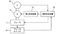
- FIG. 2 is a configuration diagram of a control system according to the first embodiment.
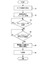
- 5 is a flowchart illustrating an example of an operation of the control system according to the first embodiment.
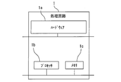
- FIG. 2 is a diagram showing a hardware configuration of a main part of the control system according to the first embodiment.
- 9 is a flowchart illustrating an example of an operation of the control system according to the second embodiment.
- FIG. 1 is a configuration diagram of an elevator to which the control system according to Embodiment 1 is applied.
- the control system 1 is applied to the elevator 2.
- the elevator 2 is provided in a building.
- the building has multiple floors.
- the hoistway passes through each floor of the building.
- the elevator 2 includes a hoist 3, a main rope 4, a car 5, a counterweight 6, and a brake 7.
- the hoisting machine 3 is provided on the hoistway.
- the hoist 3 includes an electric motor 8 and a sheave 9.
- the electric motor 8 is a device that receives power supply and rotates a rotating shaft.
- the power supplied to the motor 8 is, for example, three-phase AC power.
- the control of the motor 8 is performed, for example, by controlling the voltage or frequency of the supplied three-phase AC power.
- the sheave 9 is a device that rotates following the rotation axis of the electric motor 8.
- the main rope 4 is wound around the sheave 9 so as to be able to move following the rotation of the sheave 9.
- the car 5 is provided on the hoistway.
- the car 5 holds one end of the main rope 4 so that the car 5 can move up and down following the movement of the main rope 4 inside the hoistway.
- the counterweight 6 is provided on the hoistway. The counterweight 6 holds the other end of the main rope 4 so that it can move up and down following the movement of the main rope 4 inside the hoistway.
- the brake 7 is a device that brakes the elevation of the car 5 when the car 5 is stopped.
- the brake 7 includes, for example, a brake drum 10, a brake shoe 11, a brake coil 12, an armature 13, a brake arm 14, a spring 15, a displacement sensor 16, and a brake control device 17.
- the brake drum 10 is provided on the rotating shaft of the electric motor 8 so as to be able to rotate in synchronization with the rotating shaft of the electric motor 8.
- the brake drum 10 is, for example, a disk-shaped member.
- the brake shoe 11 faces the outer surface of the brake drum 10.
- the brake coil 12 is a device that generates a magnetic field when energized.
- the armature 13 is a device that is displaced by a magnetic field generated by the brake coil 12.
- the brake arm 14 is connected to the brake shoe 11 so that the brake shoe 11 can contact the outer surface of the brake drum 10.
- the other end of the brake arm 14 contacts the armature 13 so that the displacement of the armature 13 can be transmitted to the brake shoe 11.
- the spring 15 is provided on, for example, the brake arm 14 so that the brake shoe 11 can be pressed against the outer surface of the brake drum 10 by an elastic force.
- the displacement sensor 16 is provided on the armature 13.
- the displacement sensor 16 is a device that detects a displacement of the armature 13.
- the brake control device 17 is a device that controls the operation of the brake 7.
- the control system 1 includes an encoder 18, a brake switch 19, an operation control device 20, and a power conversion device 21.
- the encoder 18 is a device that detects a change in the rotation angle of the rotating shaft of the electric motor 8.
- the encoder 18 is provided on a rotating shaft of the electric motor 8.
- the encoder 18 includes, for example, an element that outputs a pulse signal according to a change in the rotation angle of the rotation shaft of the electric motor 8.
- the brake switch 19 is a device that detects the operation state of the brake 7.
- the operation state of the brake 7 includes braking and releasing the brake 7.
- the brake switch 19 includes, for example, a mechanism that detects an operating state of the brake 7 by detecting a mechanical displacement of a part of the brake 7.
- the displacement detected by the brake switch 19 is, for example, the displacement of the brake arm 14 by the armature 13.
- the brake switch 19 is provided on the brake arm 14, for example.
- the brake switch 19 is in the ON state.
- the brake switch 19 is in the OFF state. By switching from the ON state to the OFF state, the brake switch 19 detects the start of braking of the brake 7.
- the operation control device 20 is connected to the encoder 18 so as to receive a signal indicating a change in the rotation angle of the rotation shaft of the electric motor 8.
- the operation control device 20 is connected to the brake switch 19 so as to receive a signal indicating the operation state of the brake 7.
- the operation control device 20 is connected to the brake 7 so that a control signal can be transmitted.
- the operation control device 20 is connected to the power conversion device 21 so that a control signal can be transmitted.
- the operation control device 20 includes a timer.
- the operation control device 20 stores the delay time To.
- the initial value of the delay time To is set in advance.
- the power converter 21 is connected to an external power supply.
- the power conversion device 21 includes an element or a circuit that converts power supplied from an external power supply into three-phase AC power based on a control signal received from the operation control device 20.
- the power converter 21 is connected to the electric motor 8 so that three-phase AC power can be supplied to the electric motor 8.
- the power conversion device 21 is an example of a power supply device.
- the operation control device 20 In operation of the elevator 2, the operation control device 20 generates a torque command.
- the torque command is a command corresponding to a control target value of the torque generated by the electric motor 8.
- the operation control device 20 transmits a control signal representing the generated torque command to the power conversion device 21.
- the power converter 21 converts power supplied from an external power supply into three-phase AC power based on the received control signal.
- the power converter 21 supplies the converted three-phase AC power to the electric motor 8.
- the electric motor 8 rotates the rotating shaft by receiving the supply of the electric power.
- the sheave 9 rotates following the rotation axis of the electric motor 8.
- the car 5 moves up and down following the movement of the main rope 4 inside the hoistway.
- the counterweight 6 moves up and down following the movement of the main rope 4 inside the hoistway.
- the encoder 18 detects a change in the rotation angle of the rotation shaft of the electric motor 8.
- the encoder 18 outputs a pulse signal corresponding to a change in the rotation angle of the rotating shaft of the electric motor 8 as a signal indicating a change in the rotation angle of the rotating shaft of the electric motor 8.
- the operation control device 20 receives from the encoder 18 a signal indicating a change in the rotation angle of the rotation shaft of the electric motor 8.
- the operation control device 20 acquires information on the rotation speed of the electric motor 8 from the received signal.
- the operation control device 20 generates a torque command such that the rotation speed of the electric motor 8 matches the rotation speed indicated by the speed command.
- the speed command is a command that indicates a rotation speed corresponding to a control target value of the speed at which the car 5 moves up and down.
- the operation control device 20 does not generate a braking command.
- the brake coil 12 When the brake 7 has not received a control signal indicating a braking command from the operation control device 20, the brake coil 12 generates a magnetic field by energization.
- the armature 13 is displaced by a magnetic field generated by the brake coil 12 against the elastic force of the spring 15.
- the displacement of the armature 13 is transmitted from the brake arm 14 to the brake shoe 11.
- the brake shoe 11 is separated from the outer surface of the brake drum 10.
- the operation state of the brake 7 is release.
- the brake switch 19 detects that the brake 7 has been released.
- the brake switch 19 is in the ON state.
- the operation control device 20 transmits a control signal indicating a braking command to the brake 7.
- an unbalanced torque is applied to the sheave 9 of the hoisting machine 3.
- the unbalanced torque is a torque generated by a difference between the weight of the car 5 and the passenger riding the car 5 and the weight of the counterweight 6.
- the electric motor 8 of the hoisting machine 3 holds the rotating shaft without rotating by the torque generated by the electric power supplied from the electric power converter 21.
- the encoder 18 does not output a pulse signal.
- the brake 7 cuts off the power supply to the brake coil 12.
- the brake coil 12 does not generate a magnetic field.
- the brake shoe 11 approaches the outer surface of the brake drum 10 by the elastic force of the spring 15.
- the displacement sensor 16 detects a displacement of the armature 13.
- the displacement sensor 16 transmits a signal indicating the detected displacement to, for example, the brake control device 17.
- the brake control device 17 acquires information on the speed of the armature 13 from the received signal.
- the brake control device 17 generates a magnetic field in the brake coil 12 so as to adjust the speed of the displacement of the armature 13 based on the acquired information on the speed of the armature 13, so that the brake Reduce the speed at which the gap closes.
- the brake shoe 11 contacts the outer surface of the brake drum 10.
- the operation state of the brake 7 is braking.
- the brake switch 19 is turned off.
- the brake switch 19 detects the start of braking of the brake 7.
- the operation control device 20 starts counting the timer when the brake switch 19 is turned off. The timer continues counting until the delay time To stored in the operation control device 20 is reached.
- the brake shoe 11 While the timer continues counting, the brake shoe 11 is pressed against the outer surface of the brake drum 10 by the elastic force of the spring 15. The pressure with which the brake shoe 11 is pressed against the outer surface of the brake drum 10 gradually increases. As the pressure increases, the torque of the brake 7 gradually increases.
- the operation control device 20 transmits a control signal indicating power supply cutoff to the power conversion device 21. Based on the received control signal, power converter 21 cuts off the supply of power to electric motor 8. The electric motor 8 to which the supply of electric power is cut off does not generate torque. The operation control device 20 resets the count of the timer. The operation control device 20 restarts counting of the timer.
- the sheave 9 of the hoist 3 rotates by the unbalanced torque.
- the rotating shaft of the hoist 3 rotates together with the sheave 9.
- the brake drum 10 rotates in synchronization with the rotation shaft while being in contact with the brake shoe 11.
- the encoder 18 detects a change in the rotation angle of the rotation shaft.
- the encoder 18 outputs a pulse signal corresponding to a change in the rotation angle of the rotating shaft of the electric motor 8 as a signal indicating a change in the rotation angle of the rotating shaft of the electric motor 8.
- the operation control device 20 receives from the encoder 18 a signal indicating a change in the rotation angle of the rotation shaft of the electric motor 8.
- the brake shoe 11 is further pressed against the outer surface of the brake drum 10 by the elastic force of the spring 15.
- the pressure at which the brake shoe 11 is pressed against the outer surface of the brake drum 10 further increases.
- the torque of the brake 7 further increases.
- the rotation of the sheave 9 stops.
- the encoder 18 does not output a pulse signal.
- the operation control device 20 acquires the count of the timer when the pulse signal is no longer output from the encoder 18 as the measurement time ⁇ T.
- the operation control device 20 updates the stored delay time To as To + ⁇ T based on the measurement time ⁇ T.
- the operation control device 20 transmits a control signal indicating a braking command to the brake 7.
- the electric motor 8 of the hoisting machine 3 holds the rotating shaft without rotating by the torque generated by the electric power supplied from the electric power converter 21.
- the operation state of the brake 7 becomes braking.
- the brake switch 19 is turned off.
- the brake switch 19 detects the start of braking of the brake 7.
- the operation control device 20 starts counting the timer when the brake switch 19 is turned off. The timer continues counting until the updated delay time To stored in the operation control device 20 is reached.
- FIG. 2 is a configuration diagram of the control system according to the first embodiment.
- FIG. 3 is a flowchart illustrating an example of an operation of the control system according to the first embodiment.
- the operation control device 20 transmits a control signal indicating the generated torque command to the power conversion device 21.
- the power converter 21 converts power supplied from an external power supply into three-phase AC power based on the received control signal.
- the power converter 21 supplies the converted three-phase AC power to the electric motor 8.
- the electric motor 8 receives the supply of electric power and rotates the rotating shaft.
- the encoder 18 detects a change in the rotation angle of the rotation shaft of the electric motor 8.
- the operation control device 20 generates a torque command based on the change in the rotation angle and the speed command detected by the encoder 18.
- the car 5 moves up and down inside the hoistway according to the speed of up and down corresponding to the speed command. Thereafter, the car 5 stops at the landing position.
- step S1 of FIG. 3 the operation control device 20 detects that the car 5 has stopped at the landing position. Thereafter, the operation of the control system 1 proceeds to Step S2.
- step S2 the operation control device 20 transmits a signal indicating a braking command to the brake 7. Thereafter, the operation of the control system 1 proceeds to Step S3.
- step S3 the operation control device 20 determines whether the brake switch 19 is in the ON state. When the result of the determination is Yes, the operation of the control system 1 proceeds to step S3 again. When the determination result is No, the operation control device 20 starts counting the timer. Thereafter, the operation of the control system 1 proceeds to Step S4.
- step S4 the operation control device 20 determines whether the count of the timer has reached the delay time To. When the determination result is No, the operation of the control system 1 proceeds to step S4 again. When the determination result is Yes, the operation control device 20 resets the count of the timer. Thereafter, the operation of the control system 1 proceeds to Step S5.
- step S5 the operation control device 20 transmits a control signal indicating power supply cutoff to the power conversion device 21. After that, the power converter 21 cuts off the supply of power to the electric motor 8. Thereafter, the operation control device 20 restarts counting of the timer. Thereafter, the operation control device 20 acquires the count of the timer when the pulse signal is no longer output from the encoder 18 as the measurement time ⁇ T. Thereafter, the operation of the control system 1 proceeds to Step S6.
- step S6 the operation control device 20 updates the stored delay time To with the measurement time ⁇ T. Thereafter, the operation of the control system 1 ends.
- the control system 1 includes the power conversion device 21, the brake switch 19, and the operation control device 20.
- the power converter 21 supplies electric power to the electric motor 8.
- the electric motor 8 raises and lowers the car 5 of the elevator 2.
- the brake switch 19 detects an operation state of the brake 7.
- the brake 7 brakes the electric motor 8.
- the operation control device 20 causes the power conversion device 21 to cut off the supply of power to the electric motor 8.
- the control system 1 also includes the encoder 18.
- the encoder 18 detects a change in the rotation angle of the rotation shaft of the electric motor 8.
- the operation control device 20 measures a measurement time ⁇ T from when the power conversion device 21 cuts off the power supply to the electric motor 8 until the encoder 18 stops detecting the change in the rotation angle.
- the operation control device 20 updates the delay time To with the measured measurement time ⁇ T.
- the operation control device 20 measures the measurement time ⁇ T from when the delay time To elapses to when the torque of the brake 7 reaches the unbalanced torque.
- the operation control device 20 updates the delay time To with the measurement time ⁇ T.
- the operation control device 20 adjusts the delay time To so as to suppress the rotation of the brake drum 10 in a state where the brake shoe 11 is in contact. Thus, wear of the brake 7 is suppressed.
- the delay time To is adjusted based on the measurement time ⁇ T measured by the output of the encoder 18. Therefore, even when the state of the brake 7 changes due to elapse of time or the like, wear of the brake 7 is suppressed. Since the delay time To is adjusted based on the measurement time ⁇ T, there is no need for tuning by maintenance personnel or the like.
- the brake 7 may be, for example, a disc brake.
- the brake 7 includes, for example, a brake disk and a pair of brake pads.
- the brake disk is provided on the rotating shaft of the electric motor 8 so as to be able to rotate in synchronization with the rotating shaft of the electric motor 8.
- One of the pair of brake pads is provided on one side of the brake disc.
- the other of the pair of brake pads is provided on the other side of the brake disc.
- the brake arm 14 transmits the displacement of the armature 13 to each of the pair of brake pads.
- the brake 7 brakes the electric motor 8 by sandwiching a brake disc between a pair of brake pads.
- the brake 7 may include a displacement sensor that detects a displacement of the brake arm 14 or the brake shoe 11 or the like.
- the brake 7 may include a speed sensor that detects the speed of the armature 13, the brake arm 14, the brake shoe 11, or the like.
- the encoder 18 may directly detect a change in the rotation angle of the rotation shaft of the electric motor 8.
- the encoder 18 may detect a rotation position of a rotation shaft of the electric motor 8.
- the encoder 18 may indirectly detect a change in the rotation angle of the rotation shaft of the electric motor 8 based on the detected rotation position.
- the operation control device 20 does not need to update the delay time To when the encoder 18 does not detect a change in the rotation angle after the power conversion device 21 shuts off the power supply to the electric motor 8.
- FIG. 4 is a diagram illustrating a hardware configuration of a main part of the control system according to the first embodiment.
- Each function of the control system 1 can be realized by a processing circuit.
- the processing circuit includes at least one processor 1b and at least one memory 1c.
- the processing circuit may include at least one dedicated hardware 1a together with or as a substitute for the processor 1b and the memory 1c.
- each function of the control system 1 is realized by software, firmware, or a combination of software and firmware. At least one of software and firmware is described as a program.
- the program is stored in the memory 1c.
- the processor 1b implements each function of the control system 1 by reading and executing a program stored in the memory 1c.
- the processor 1b is also referred to as a CPU (Central Processing Unit), a processing device, an arithmetic device, a microprocessor, a microcomputer, or a DSP.
- the memory 1c includes, for example, a nonvolatile or volatile semiconductor memory such as a RAM, a ROM, a flash memory, an EPROM, and an EEPROM, a magnetic disk, a flexible disk, an optical disk, a compact disk, a mini disk, and a DVD.
- a nonvolatile or volatile semiconductor memory such as a RAM, a ROM, a flash memory, an EPROM, and an EEPROM, a magnetic disk, a flexible disk, an optical disk, a compact disk, a mini disk, and a DVD.
- the processing circuit includes the dedicated hardware 1a
- the processing circuit is realized by, for example, a single circuit, a composite circuit, a programmed processor, a parallel programmed processor, an ASIC, an FPGA, or a combination thereof.
- Each function of the control system 1 can be realized by a processing circuit.
- each function of the control system 1 can be realized by a processing circuit collectively.
- a part of each function of the control system 1 may be realized by dedicated hardware 1a, and the other part may be realized by software or firmware.
- the processing circuit implements each function of the control system 1 by hardware 1a, software, firmware, or a combination thereof.
- the function of the brake control device 17 may be realized by hardware common to the control system 1 or the like.
- Embodiment 2 FIG. In the second embodiment, points different from the example disclosed in the first embodiment will be described in detail. As for features not described in the second embodiment, any of the features disclosed in the first embodiment may be adopted.
- FIG. 5 is a flowchart illustrating an example of an operation of the control system according to the second embodiment.
- control system 1 according to the second embodiment operates in the same manner as the control system 1 according to the first embodiment from step S1 to step S6. After updating the delay time To stored in the operation control device 20 in step S6, the operation of the control system 1 according to the second embodiment proceeds to step S7.
- step S7 the operation control device 20 determines whether the updated delay time To is longer than a predetermined abnormality detection time.
- the operation of the control system 1 proceeds to step S8.
- the result of the determination is No, the operation of the control system 1 ends.
- step S8 the operation control device 20 detects an abnormality of the brake 7. Thereafter, the operation control device 20 disables the use of the elevator 2. Thereafter, the operation of the control system 1 ends.
- the operation control device 20 detects the abnormality of the brake 7.
- the operation control device 20 can detect an abnormality of the brake 7 during operation.
- the operation control device 20 When detecting an abnormality of the brake 7, the operation control device 20 disables the use of the elevator 2.
- the operation control device 20 disables the use of the elevator 2 when an abnormality has occurred in the brake 7.
- the operation of the elevator 2 in a state where the abnormality of the brake 7 has occurred is prevented beforehand.
- the operation control device 20 may report information of the detected abnormality to, for example, a facility or facility that manages information of the elevator 2.
- the operation control device 20 may disable the use of the elevator 2 by, for example, not generating a torque command.
- the operation control device 20 may transmit a control signal indicating an abnormality of the brake 7 to, for example, a device that receives a call from a user. At this time, the device or the like that has received the control signal does not accept the call from the user. As a result, the use of the elevator 2 becomes impossible.
- control system according to the present invention can be applied to an elevator.
- 1 control system 1a hardware, 1b processor, 1c memory, 2 elevator, 3 hoist, 4 main rope, 5 car, 6 balance weight, 7 brake, 8 electric motor, 9 sheave, 10 brake drum, 11 brake shoe , ⁇ 12 ⁇ brake coil, ⁇ 13 ⁇ armature, ⁇ 14 ⁇ brake arm, ⁇ 15 ⁇ spring, ⁇ 16 ⁇ displacement sensor, ⁇ 17 ⁇ brake controller, ⁇ 18 ⁇ encoder, ⁇ 19 ⁇ brake switch, ⁇ 20 ⁇ operation controller, ⁇ 21 ⁇ power converter
Landscapes
- Engineering & Computer Science (AREA)
- Automation & Control Theory (AREA)
- Elevator Control (AREA)
- Braking Arrangements (AREA)
Abstract
Le but de la présente invention est de fournir un système de commande (1) pour réduire l'usure des freins (7). Le système de commande (1) comprend un dispositif de conversion d'énergie (21), un commutateur de frein (19) et un dispositif de commande de fonctionnement (20). Le dispositif de conversion d'énergie (21) fournit de l'énergie à un moteur électrique (8). Le moteur électrique (8) lève et abaisse une cabine (5) d'un ascenseur (2). Le commutateur de frein (19) détecte l'état de fonctionnement du frein (7). Le frein (7) freine le moteur électrique (8). Le dispositif de commande de fonctionnement (20) amène le dispositif de conversion d'énergie (21) à bloquer l'alimentation en énergie du moteur électrique (8) après qu'un temps de retard To à partir du moment où le commutateur de frein (19) détecte que le frein (7) est en train de fonctionner est passé.
Priority Applications (3)
| Application Number | Priority Date | Filing Date | Title |
|---|---|---|---|
| CN201880093575.9A CN112292341B (zh) | 2018-06-25 | 2018-06-25 | 电梯的控制系统 |
| JP2020526736A JP6912006B2 (ja) | 2018-06-25 | 2018-06-25 | エレベーターの制御システム |
| PCT/JP2018/024047 WO2020003356A1 (fr) | 2018-06-25 | 2018-06-25 | Système de commande d'ascenseur |
Applications Claiming Priority (1)
| Application Number | Priority Date | Filing Date | Title |
|---|---|---|---|
| PCT/JP2018/024047 WO2020003356A1 (fr) | 2018-06-25 | 2018-06-25 | Système de commande d'ascenseur |
Publications (1)
| Publication Number | Publication Date |
|---|---|
| WO2020003356A1 true WO2020003356A1 (fr) | 2020-01-02 |
Family
ID=68984731
Family Applications (1)
| Application Number | Title | Priority Date | Filing Date |
|---|---|---|---|
| PCT/JP2018/024047 Ceased WO2020003356A1 (fr) | 2018-06-25 | 2018-06-25 | Système de commande d'ascenseur |
Country Status (3)
| Country | Link |
|---|---|
| JP (1) | JP6912006B2 (fr) |
| CN (1) | CN112292341B (fr) |
| WO (1) | WO2020003356A1 (fr) |
Cited By (1)
| Publication number | Priority date | Publication date | Assignee | Title |
|---|---|---|---|---|
| US12559343B2 (en) | 2020-12-04 | 2026-02-24 | Otis Elevator Company | Emergency terminal deceleration in elevator systems |
Citations (3)
| Publication number | Priority date | Publication date | Assignee | Title |
|---|---|---|---|---|
| JP2006096510A (ja) * | 2004-09-29 | 2006-04-13 | Mitsubishi Electric Corp | エレベータ装置 |
| JP2013124179A (ja) * | 2011-12-16 | 2013-06-24 | Hitachi Ltd | エレベータシステム及びエレベータの制御方法 |
| JP2017214223A (ja) * | 2012-05-31 | 2017-12-07 | コネ コーポレイションKone Corporation | ブレーキコントローラおよびエレベータシステム |
Family Cites Families (7)
| Publication number | Priority date | Publication date | Assignee | Title |
|---|---|---|---|---|
| GB1309134A (en) * | 1969-06-30 | 1973-03-07 | Westinghouse Electric Corp | Electric motor control system |
| JPH0930750A (ja) * | 1995-07-14 | 1997-02-04 | Hitachi Building Syst Co Ltd | エレベーターのブレーキ特性評価装置 |
| WO2010095243A1 (fr) * | 2009-02-20 | 2010-08-26 | 三菱電機株式会社 | Dispositif de freinage pour ascenseur |
| JP2012025526A (ja) * | 2010-07-22 | 2012-02-09 | Toshiba Elevator Co Ltd | エレベータのブレーキ異常検出システムおよび方法 |
| JP5932577B2 (ja) * | 2012-09-06 | 2016-06-08 | 株式会社日立製作所 | エレベータの安全システム |
| CN103407850B (zh) * | 2013-07-31 | 2015-05-06 | 日立电梯(中国)有限公司 | 电梯智能制动控制方法与装置 |
| JP6449806B2 (ja) * | 2016-03-30 | 2019-01-09 | 株式会社日立製作所 | エレベータ装置及びその動作制御方法 |
-
2018
- 2018-06-25 JP JP2020526736A patent/JP6912006B2/ja active Active
- 2018-06-25 WO PCT/JP2018/024047 patent/WO2020003356A1/fr not_active Ceased
- 2018-06-25 CN CN201880093575.9A patent/CN112292341B/zh active Active
Patent Citations (3)
| Publication number | Priority date | Publication date | Assignee | Title |
|---|---|---|---|---|
| JP2006096510A (ja) * | 2004-09-29 | 2006-04-13 | Mitsubishi Electric Corp | エレベータ装置 |
| JP2013124179A (ja) * | 2011-12-16 | 2013-06-24 | Hitachi Ltd | エレベータシステム及びエレベータの制御方法 |
| JP2017214223A (ja) * | 2012-05-31 | 2017-12-07 | コネ コーポレイションKone Corporation | ブレーキコントローラおよびエレベータシステム |
Cited By (1)
| Publication number | Priority date | Publication date | Assignee | Title |
|---|---|---|---|---|
| US12559343B2 (en) | 2020-12-04 | 2026-02-24 | Otis Elevator Company | Emergency terminal deceleration in elevator systems |
Also Published As
| Publication number | Publication date |
|---|---|
| JPWO2020003356A1 (ja) | 2021-02-15 |
| JP6912006B2 (ja) | 2021-07-28 |
| CN112292341B (zh) | 2022-05-31 |
| CN112292341A (zh) | 2021-01-29 |
Similar Documents
| Publication | Publication Date | Title |
|---|---|---|
| JP5474040B2 (ja) | エレベータのブレーキ装置 | |
| CN105283404B (zh) | 用于人员运送设备的制动方法、用于执行制动方法的制动控制装置以及具有制动控制装置的人员运送设备 | |
| JP5079517B2 (ja) | エレベーターの非常停止システム | |
| KR100973881B1 (ko) | 엘리베이터 장치 | |
| JP5053075B2 (ja) | エレベータ装置 | |
| JP5138361B2 (ja) | エレベータ装置 | |
| JPWO2008117423A1 (ja) | エレベータのブレーキ装置 | |
| EP2321211B1 (fr) | Système d'ascenseur, et procédé en conjonction avec un système d'ascenseur | |
| CN108698790B (zh) | 电梯以及救援运转控制方法 | |
| JP2014169186A (ja) | トラクションシーブエレベータおよびトラクションシーブの駆動方法 | |
| JPH07206288A (ja) | エレベーター | |
| JP2011143982A (ja) | エレベータの制動制御装置及び制動制御方法 | |
| JP5031767B2 (ja) | エレベータ装置 | |
| JP6912006B2 (ja) | エレベーターの制御システム | |
| KR101250735B1 (ko) | 엘리베이터 장치 | |
| JP6655489B2 (ja) | エレベーター | |
| JP6449806B2 (ja) | エレベータ装置及びその動作制御方法 | |
| JP6821086B2 (ja) | エレベーター制御装置およびエレベーター制御方法 | |
| JP5774166B2 (ja) | エレベータ装置 | |
| US20240059522A1 (en) | Elevator system | |
| JP2007084174A (ja) | エレベーターのブレーキ装置 | |
| HK40046326A (en) | A method for monitoring brake dragging of an elevator | |
| JP2019001649A (ja) | エレベータ装置及びその制御方法 | |
| HK1214578B (en) | Braking method for a passenger transport system, brake control for carrying out the braking method and passenger transport system having a brake control |
Legal Events
| Date | Code | Title | Description |
|---|---|---|---|
| 121 | Ep: the epo has been informed by wipo that ep was designated in this application |
Ref document number: 18923776 Country of ref document: EP Kind code of ref document: A1 |
|
| ENP | Entry into the national phase |
Ref document number: 2020526736 Country of ref document: JP Kind code of ref document: A |
|
| NENP | Non-entry into the national phase |
Ref country code: DE |
|
| 122 | Ep: pct application non-entry in european phase |
Ref document number: 18923776 Country of ref document: EP Kind code of ref document: A1 |