WO2020003409A1 - Dispositif d'alignement et de transport - Google Patents
Dispositif d'alignement et de transport Download PDFInfo
- Publication number
- WO2020003409A1 WO2020003409A1 PCT/JP2018/024379 JP2018024379W WO2020003409A1 WO 2020003409 A1 WO2020003409 A1 WO 2020003409A1 JP 2018024379 W JP2018024379 W JP 2018024379W WO 2020003409 A1 WO2020003409 A1 WO 2020003409A1
- Authority
- WO
- WIPO (PCT)
- Prior art keywords
- transport
- trough
- articles
- article
- alignment
- Prior art date
- Legal status (The legal status is an assumption and is not a legal conclusion. Google has not performed a legal analysis and makes no representation as to the accuracy of the status listed.)
- Ceased
Links
Images





Classifications
-
- B—PERFORMING OPERATIONS; TRANSPORTING
- B65—CONVEYING; PACKING; STORING; HANDLING THIN OR FILAMENTARY MATERIAL
- B65B—MACHINES, APPARATUS OR DEVICES FOR, OR METHODS OF, PACKAGING ARTICLES OR MATERIALS; UNPACKING
- B65B35/00—Supplying, feeding, arranging or orientating articles to be packaged
- B65B35/30—Arranging and feeding articles in groups
- B65B35/34—Arranging and feeding articles in groups by agitators or vibrators
-
- B—PERFORMING OPERATIONS; TRANSPORTING
- B65—CONVEYING; PACKING; STORING; HANDLING THIN OR FILAMENTARY MATERIAL
- B65G—TRANSPORT OR STORAGE DEVICES, e.g. CONVEYORS FOR LOADING OR TIPPING, SHOP CONVEYOR SYSTEMS OR PNEUMATIC TUBE CONVEYORS
- B65G27/00—Jigging conveyors
- B65G27/10—Applications of devices for generating or transmitting jigging movements
- B65G27/16—Applications of devices for generating or transmitting jigging movements of vibrators, i.e. devices for producing movements of high frequency and small amplitude
- B65G27/18—Mechanical devices
-
- B—PERFORMING OPERATIONS; TRANSPORTING
- B65—CONVEYING; PACKING; STORING; HANDLING THIN OR FILAMENTARY MATERIAL
- B65G—TRANSPORT OR STORAGE DEVICES, e.g. CONVEYORS FOR LOADING OR TIPPING, SHOP CONVEYOR SYSTEMS OR PNEUMATIC TUBE CONVEYORS
- B65G47/00—Article or material-handling devices associated with conveyors; Methods employing such devices
- B65G47/02—Devices for feeding articles or materials to conveyors
- B65G47/04—Devices for feeding articles or materials to conveyors for feeding articles
- B65G47/12—Devices for feeding articles or materials to conveyors for feeding articles from disorderly-arranged article piles or from loose assemblages of articles
- B65G47/14—Devices for feeding articles or materials to conveyors for feeding articles from disorderly-arranged article piles or from loose assemblages of articles arranging or orientating the articles by mechanical or pneumatic means during feeding
-
- B—PERFORMING OPERATIONS; TRANSPORTING
- B65—CONVEYING; PACKING; STORING; HANDLING THIN OR FILAMENTARY MATERIAL
- B65G—TRANSPORT OR STORAGE DEVICES, e.g. CONVEYORS FOR LOADING OR TIPPING, SHOP CONVEYOR SYSTEMS OR PNEUMATIC TUBE CONVEYORS
- B65G47/00—Article or material-handling devices associated with conveyors; Methods employing such devices
- B65G47/52—Devices for transferring articles or materials between conveyors i.e. discharging or feeding devices
-
- G—PHYSICS
- G01—MEASURING; TESTING
- G01G—WEIGHING
- G01G19/00—Weighing apparatus or methods adapted for special purposes not provided for in the preceding groups
- G01G19/387—Weighing apparatus or methods adapted for special purposes not provided for in the preceding groups for combinatorial weighing, i.e. selecting a combination of articles whose total weight or number is closest to a desired value
Definitions
- the present invention relates to an aligning / transporting device that transports articles while aligning them, and more particularly, to an aligning / transporting device suitable for transporting relatively soft and elongated articles while aligning them.
- Patent Document 1 As an apparatus for conveying articles while aligning them, for example, there is an apparatus described in Patent Document 1.
- an elongated rod-shaped article dispersed and conveyed by a circular feeder is vibrated and conveyed by a straight-ahead feeder and supplied to an intermediate hopper and a weighing hopper.
- a plurality of alignment pieces perpendicular to the article transport direction are provided at appropriate intervals on the transport surface of the linear feeder so that the articles are aligned in a posture parallel to the alignment pieces.
- Patent Literature 1 is directed to a hard rod-shaped article that does not bend or break due to a slight impact, for example, is cut into a long and thin shape by sandwiching cheese between dried sheets mainly made of cod surimi. When applied to relatively soft and slender articles such as cheese cod or jerky, it is easy to carry them out without sufficient alignment.
- the present invention has been made in view of such a situation, and an object of the present invention is to provide an aligning / conveying apparatus capable of conveying relatively soft and elongated articles while aligning them.
- the present invention is configured as follows.
- the aligning / conveying device includes a plurality of conveying troughs arranged along the conveying direction of the article, and each of the conveying troughs is driven to vibrate to move the conveying trough to the uppermost conveying trough in the conveying direction.
- the supplied articles are aligned while being vibrated and conveyed in the conveying direction.
- the plurality of conveying troughs arranged along the conveying direction can adjust the alignment in a stepwise manner.
- Good alignment can be achieved.
- relatively soft and elongated articles such as cheese cod and jerky can be aligned without bending or breaking.
- the transport surface of the transport trough has a wavy shape that is continuous at a constant pitch in the transport direction.
- the corrugated shape refers to a shape in which convex portions and concave portions are alternately repeated.
- the shapes of the projections and the depressions are arbitrary, such as arcs, triangles, and squares.
- the elongated article is vibrated and conveyed by the conveying trough, and repeatedly passes through the corrugated concave and convex portions that are continuous at a constant pitch in the conveying direction, so that the lateral posture along the corrugated shape, that is, The article is conveyed while being aligned in a posture in which the longitudinal direction of the article is orthogonal to the conveying direction.
- a shutter for opening and closing a transport path of a transport trough on the lowermost side in the transport direction, wherein the shutter is provided on the lowermost side.
- the transfer trough is provided at an end of the transfer direction in the transfer direction.
- the article that has reached the transport end of the transport trough on the lowermost side in the transport direction of the article is subjected to vibration while being received in the horizontal position along the shutter, and is more ordered while receiving the vibration. Become aligned. With the opening of the shutter, the articles in the aligned state with the horizontal orientation are unloaded.
- transport troughs other than the lowermost transport trough are moved to the terminal end in the transport direction to suppress transport of articles. It has a suppressing member.
- the movement suppressing member can provide an appropriate conveyance resistance to the articles, and can suppress a large amount of articles from being conveyed from the end of the conveyance trough at once, and the posture from being collapsed. Immediately before being carried out, by giving an appropriate conveyance resistance to the articles, there is also an effect of adjusting the posture of the articles whose alignment is insufficient.
- the movement suppressing member extends in the transport direction from the corrugated transport surface of the transport trough, and a tip end side thereof is inclined upward.
- the conveyance resistance applied to the conveyed article can be adjusted by appropriately selecting the upward inclination angle of the front end of the movement suppressing member and the length in the conveyance direction. As a result, it is possible to carry out a desired amount of articles from the upper transport trough to the lower transport trough in the transport direction of the articles.
- the article is conveyed by vibration and supplied to a weighing unit of a combination weigher.
- a relatively soft and elongated article can be supplied to a combination weigher in an aligned state and weighed in combination.
- a relatively soft and elongated article can be carried out in an aligned state without bending or folding.
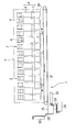
- FIG. 1 is an overall perspective view of a combination weighing device provided with an alignment transport device according to one embodiment of the present invention.
- FIG. 2 is a schematic front view schematically showing the combination weighing device of FIG.
- FIG. 3 is a schematic side view schematically showing the combination weighing device of FIG.
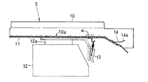
- FIG. 4 is a vertical sectional side view of the upper straight feeder of the aligning and conveying device.
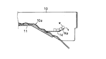
- FIG. 5 is a longitudinal sectional side view in which the terminal portion of the upper straight feeder of the aligning and conveying device is enlarged.
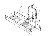
- FIG. 6 is a perspective view of an upper straight feeder of the aligning and conveying device.
- FIG. 7 is a perspective view of the lower straight feeder of the aligning and conveying device.
- FIG. 8 is a vertical cross-sectional view of the collecting and sorting unit.
- FIG. 9 is a perspective view of the collecting trough of the collecting and aligning unit.
- FIG. 10 is a front view of the collecting trough of the collecting and sorting unit.
- FIG. 1 is a perspective view of a combination weighing device provided with an alignment transport device according to an embodiment of the present invention
- FIG. 2 is a schematic front view schematically showing the combination weighing device of FIG. 1
- FIG. FIG. 2 is a schematic side view schematically showing the combination weighing device of FIG.
- left-right direction in FIG. 2 and the front-back direction in FIG. 3 are referred to as left-right direction, and the front-back direction in FIG. 2 and the left-right direction in FIG. I will do it.
- the combination weighing device of this embodiment is, for example, for weighing and discharging relatively soft and slender articles such as cheese cod or jerky which is cut into strips with cheese sandwiched between dried sheets whose main raw material is cod surimi. It is a suitable combination weighing device.
- This combination weighing apparatus combines a combination weigher 1 that weighs and discharges articles such as cheese cod, and conveys the articles discharged from the combination weigher 1 to one side (left side in this example) and collects and aligns them. And a set sorting / unloading unit 2 for unloading.
- the combination weigher 1 arranged at the upper part includes an alignment conveyance device 3 for arranging articles while conveying the articles forward in a multi-path system in which the articles are arranged in the left-right direction, in this example, 14 alignment conveyance paths, and each of the alignment conveyance apparatuses 3
- a plurality of (in this example, 14) weighing units 4 are arranged side by side in one direction, in this example, in the lateral direction.
- One alignment conveyance path in the alignment conveyance device 3 of this embodiment is configured by arranging three straight-ahead feeders 5 in a stepwise manner in a descending forward direction along the article conveyance direction.
- the articles conveyed in each alignment conveyance path are supplied to each corresponding weighing unit 4.
- Each weighing unit 4 receives a supply hopper 6 that receives and conveys and holds the articles conveyed on each alignment conveyance path in the alignment conveyance device 3, and a weighing unit that receives the articles w discharged from the supply hopper 6 and measures the weight thereof. And a hopper 7.
- each hopper 6, 7 is embossed in order to reduce friction with an article.
- the combination weigher 1 performs combination weighing in the same manner as in the related art. That is, the control device (not shown) of the combination weigher 1 determines that the combination weight obtained by variously combining the weights of the articles weighed by the plurality of weighing hoppers 7 is equal to or closest to the target combination weight. A combination calculation is performed to select an appropriate combination that is a combination of the weighing hoppers 7 within the range. The articles w of the weighing hopper 7 selected as the appropriate quantity combination by this combination calculation are discharged downward.
- the weighing hopper 7 is provided with a pair of front and rear gates 7a and 7b which open and close independently in opposite directions. By selectively opening one of the gates 7a and 7b 7a (7b), the held articles can be discharged through two front and rear paths.
- FIGS. 4 to 7 are views showing the structure of the straight-ahead feeder 5 constituting the aligning / conveying apparatus 3.
- FIG. 4 is a vertical sectional side view showing the uppermost linear feeder 5 which is the uppermost side in the transport direction of the article.
- FIG. 5 is a vertical sectional side view in which the terminal end in the transport direction is enlarged. It is the perspective view.
- FIG. 7 is a perspective view of the lower straight feeder 5 which is the lowermost side in the article conveying direction among the three straight feeders 5.
- Each of the linear feeders 5 of each stage has a structure including a transport trough 10 having a pair of side plates erected from both ends in the width direction of the bottom plate, and a connecting plate 11 on the lower surface of the bottom plate of the transport trough 10. ing. As shown in FIG. 4, the connection plate 11 is positioned and locked on a vibration head portion 12a of a vibrator 12, and is detachably connected by a buckle-shaped fastener 13.
- the bottom surface 10a which is the transport surface of the transport trough 10, is formed in a continuous wave shape having a pitch of, for example, about 15 mm and a depth of, for example, about 2 mm, in the transport direction (front-back direction) of the article w.
- the corrugated pitch of the bottom surface 10a is a pitch corresponding to the width of one article w such that one article w enters the corrugated recess and becomes horizontal.
- the elongated article w placed on the bottom surface 10a of the transport trough 10 is laterally oriented along the waveform by being vibrated, that is, while its longitudinal direction is aligned in an attitude orthogonal to the transport direction of the article w. , And is conveyed forward by vibration.
- the elongated article w is vibrated and conveyed by the conveying trough 10, it repeatedly passes through the corrugated concave portions and convex portions that are continuous at a constant pitch in the conveying direction, and is aligned in a horizontal posture along the corrugated shape. Conveyed.
- the transport direction of the articles w by the transport trough 10 is forward, and the arrangement direction of the plurality of weighing units 4 is the horizontal direction. Therefore, the direction orthogonal to the transport direction of the articles w is the arrangement direction of the plurality of weighing units 4. Some horizontal direction. Therefore, the article w is vibrated and conveyed by the vibration conveyance by the conveyance trough 10 while its longitudinal direction is aligned in the horizontal direction, which is the arrangement direction of the plurality of weighing units 4.
- the transport trough 10 in the upper and middle straight feeders 5 has a bottom surface 10a whose front end side is inclined forward and downward, and is provided with a movement suppressing plate 14 for suppressing the transfer movement of articles.
- the movement suppressing plate 14 of this embodiment is made of a wide flat plate material on which the article w can be stably placed in a horizontal position.
- the movement restraining plate 14 extends horizontally from the bottom surface 10a of the transport trough 10 in the transport direction, and has an inclined rising portion 14a which is slightly upwardly inclined at the front end thereof.
- the article w vibrated and conveyed on the corrugated bottom surface 10a is pushed onto the movement suppressing plate 14, and then pushed by the following article w to move on the movement suppressing plate 14, and the terminal end rises inclining.
- the movement of the article w is suppressed in the section 14a, and the article w is carried out little by little over the inclined rising section 14a by the subsequent extrusion conveyance.
- the movement suppressing plate 14 applies an appropriate conveyance resistance to the articles w in the lateral orientation, and suppresses a large amount of articles w from being sent from the end of the trough at once, and the orientation is suppressed.
- Immediately before being carried out by imparting conveyance resistance to the articles, there is also an effect of adjusting the posture of the articles that are not sufficiently aligned.
- the movement suppressing plate 14 is not limited to a flat plate shape, but may be a comb tooth shape or the like.
- a transport trough shutter 15 that can be swung up and opened around an upper fulcrum p is provided at the end of the transport trough 10 in the lower straight feeder 5 that is the final stage, as shown in FIG.
- the transport trough shutter 15 opens and closes the end of the transport path by the transport trough 10 by the air cylinder 16.
- elongated articles are collectively supplied to the transport trough 10 of the upper straight feeder 5 using a robot hand (not shown).
- the articles supplied to the upper straight feeder 5 are vibrated and conveyed sequentially to the middle straight feeder 5 and the lower straight feeder 5 to be laterally aligned.
- the vibration amplitude of the upper straight feeder 5 to which articles are supplied collectively is maximized, the vibration time is minimized, the vibration amplitude of the lower straight feeder 5 is minimized, and the vibration time is maximized.
- the articles supplied in a state of being gathered in the upper straight feeder 5 are sequentially vibrated and conveyed to the middle straight feeder 5 and the lower straight feeder 5 by an appropriate amount, and the lower straight feeder 5 disperses the articles.
- One article w can be laterally aligned such that one article w enters the corrugated depression on the bottom surface 10a of the transport trough 10.
- Each of the rectilinear feeders 5 starts driving when the articles are discharged from the supply hopper 6 and the supply hopper 6 becomes empty.
- the step between the upper straight feeder 5 and the middle straight feeder 5 and the difference between the middle straight feeder 5 and the lower straight feeder 5 are caused when the article falls and is transferred to the next straight feeder 5.
- the waveform of the bottom surface 10a of the transport trough 10 may be, for example, a sine waveform, or a sawtooth waveform with a steep rising surface facing the transport direction. .
- the collective alignment unloading section 2 below the combination weigher 1 receives the articles w discharged from the plurality of weighing hoppers 7 of the combination weigher 1 and arranges the plurality of weighing units 4 in the arrangement direction.
- a transport conveyor 21 for transporting along the horizontal direction.
- two front and rear conveyors 21 for conveying the article w to the left are provided, and each conveyor 21 is constituted by a belt conveyor.
- Each transport conveyor 21 is supported so as to be able to move back and forth along a guide rail 22 shown in FIG. 1 and is individually moved back and forth by a predetermined stroke by an actuator 23 such as an air cylinder.
- the rearward movement position of the front (right side in FIG. 3) conveyor 21 is the receiving position (a) for articles facing the discharge path forward of the weighing hopper 7.
- the forward movement position of the rear conveyor (the left side in FIG. 3) is the receiving position (a) for articles facing the discharge path behind the weighing hopper 7.
- a pair of front and rear guides 24 is provided on both sides of each conveyor 21 in the width direction so as to extend upward along the conveyance path.
- the guides 24 guide the articles w discharged from the weighing hopper 7 onto the belt without spilling.
- a plurality of collective troughs 25 into which the articles w discharged from the respective conveyors 21 are placed are arranged on the lower side of the conveyor 21 in the conveying direction.
- each collecting trough 25 is located at a receiving position (a) where each conveyor 21 receives the articles discharged from the weighing hopper 7, and at a retracting position (b) outside the receiving position.
- the four conveyors 21 are provided in a line in front and rear so as to face the end of each conveyor 21 at the time.
- the articles discharged from the weighing hopper 7 of the combination weigher 1 are transported by the two transport conveyors 21 at the receiving position (a) or the retreat position (b), and the four collective troughs are transported along four transport paths. 25.
- the conveyor 21 is driven for a certain time when the articles are put into the collecting trough 25.
- FIG. 8 is a longitudinal sectional view of the collecting and sorting unit 2
- FIG. 9 is a perspective view of the collecting trough 25 of the collecting and sorting unit 2
- FIG. 10 is a front view of the collecting trough 25.
- the collective trough 25 into which articles are input from the conveyor 21 has a concave and curved bottom, and a trough body 25a having an open U-shaped cross section is surrounded by a support plate 25b and reinforced. It has a supported structure.
- the trough main body 25a is embossed to reduce friction with an article.
- the support plate 25b has a structure in which a pair of side plates are erected from both ends in the width direction of the bottom plate.
- the connecting table 25c connected to the lower surface of the support plate 25b is positioned and locked on the vibration head 26a of the vibrator 26, and is detachably connected by a buckle-shaped fastener 27.
- a pusher 33 that can move forward and backward in the longitudinal direction of the trough by the air cylinder 32 is provided on the inner back of each of the collective troughs 25.
- a long and narrow article w is supplied to the starting end of the straight-line feeder 5 in the conveying direction in the conveying direction of the aligning and conveying device 3 using a robot hand or the like (not shown).
- the article w supplied to the start end of the upper straight feeder 5 is first subjected to the vibration conveying action of the straight feeder 5, and is aligned with the wave shape of the bottom surface 10a of the transfer trough 10, that is, while being aligned in the horizontal position, Sent to The article w which has reached the terminal end of the transport trough 10 of the upper straight feeder 5 is transferred to the middle straight feeder 5 over the movement suppressing plate 14 while maintaining the horizontal posture. Similarly, the middle straight feeder 5 is sent forward while being aligned in a horizontal position along the corrugation of the bottom surface 10a of the transport trough 10, and is sent into the lower straight feeder 5.
- the sheet is fed forward while being aligned in the horizontal position, and is received and held by the transport trough shutter 15.
- the transport trough shutter 15 is controlled to open for a predetermined time, and a small amount of articles is supplied to the supply hopper 6 in a horizontal position. Then, when the articles w are discharged from the weighing hopper 7 weighed by the weighing hopper 7 and selected as a proper combination by the combination calculation and become empty, the supply hopper 6 is opened and a new article w is supplied to the weighing hopper 7. You.
- Either one of the gates 7a, 7b (7b) of the plurality of weighing hoppers 7 selected in the proper amount combination within the predetermined weight range by the combination operation is selectively opened and controlled, and the article w having the predetermined weight range is moved forward or forward. It is dropped and discharged to the rear discharge path.
- the alignment state of the plurality of articles w dropped and discharged from the weighing hopper 7 is not largely collapsed, and the articles w are dropped and discharged in a substantially horizontal posture.
- the articles w discharged from the weighing hopper 7 are dropped and supplied at a plurality of locations in the transport direction of the transport conveyor 21 located at the receiving position (a) with the longitudinal direction of the articles in a horizontal position substantially along the transport direction of the transport conveyor 21. Is done.
- the conveyor 21 having received the article w selects either the receiving position (a) or the retreat position (b) as the article unloading position according to the condition of the collecting trough 25, and moves forward and backward for each conveyor 21.
- the transport is performed toward the collective trough 25 arranged corresponding to the two systems of unloading positions.
- the entire amount of the articles w discharged from the weighing hopper 7 and dropped and supplied to a plurality of locations in the transport direction of the transport conveyor 21 is thrown into the collective trough 25, so that the articles w of a predetermined weight range are carried into the collective trough 25. Will be accommodated.
- each transport conveyor 21 also basically alternately carries out articles in a predetermined weight range to the collecting trough 25 corresponding to the receiving position (a) and the collecting trough 25 corresponding to the retreat position (b). .
- the articles w in the predetermined weight range put into the collective trough 25 are subjected to a vibrating and conveying action in a posture along the longitudinal direction of the concave and curved bottom surface, conveyed while being aligned in parallel with each other, and received by the collective trough shutter 29. Can be stopped.
- the pusher 33 is retracted to a position where the loading of the articles is not hindered.
- the pusher 33 repeats advancing and retreating to the predetermined position (c) shown in FIG. 8 a predetermined number of times at a low speed, and taps the rear end of the article w being subjected to the vibration conveyance action.
- the predetermined position (c) at which the rear end of the articles w is aligned and the pusher 33 waits is a position slightly behind the rear end position of the articles w received and stacked by the collective trough shutter 29. Therefore, the rear end of the article w received by the collective trough shutter 29 is not forcibly pressed.
- the articles w discharged from the four collecting troughs 25 are conveyed to the packaging step by appropriate means.
- a tray-shaped carrier supported by a robot arm or the like is made to stand by at a discharge point of the collective trough 25, and the articles w discharged in an aligned state from the collective trough 25 are received by the carrier.
- the transporting tool is moved to the conveyor line of the packaging container, the articles are transferred and loaded from the transporting tool to the packaging container that is transported at a constant pitch, and then the packaging container containing the article is sent to the sealing process. , Etc. are performed.
- the conveyor 21 is configured to be reversible. For example, when an excessive amount of articles that are difficult to be selected as an appropriate combination is supplied to the weighing hopper 7, the excessive amount of articles is discharged from the weighing hopper 7 to the transport conveyor 21, and the transport conveyor 21 is driven in reverse. Thereby, the excessive amount of articles is discharged to the collection box 35 shown in FIG.
- the articles w are aligned by the three-stage rectilinear feeders 5 so that the longitudinal direction thereof is along the horizontal direction which is the arrangement direction of the plurality of weighing units 4. It can be supplied to the supply hopper 6.
- the shape of the bottom surface of the transport trough 10 constituting the straight-ahead feeder 5 in the aligning and transporting device 3 is not limited to the corrugated shape as long as it can guide and guide the elongated articles in the horizontal direction and can pass over them.
- each transport trough 10 in the plurality of linear feeders 5 arranged along the transport direction of the articles may be different for each linear feeder 5.
- the corrugated pitch and height of the bottom surface 10a of the transport trough 10 of the straight-line feeder 5 on the upstream side in the article transport direction are increased, and the bottom surface 10a of the transport trough 10 of the straight-line feeder 5 on the downstream side in the article transport direction is increased.
- the pitch and height of the corrugations may be reduced, or the like, so that the alignment function and the transport function are different for each straight-ahead feeder 5.
- the number of the linear feeders 5 constituting the alignment supply unit 3 is not limited to three, but may be less than three or four or more.
- the aligning and transporting device 3 of the present invention is suitable for aligning and transporting articles such as relatively soft and elongated cheese cod, but can also be applied to aligning and transporting relatively hard and elongated articles such as stick pans. it can.
Landscapes
- Engineering & Computer Science (AREA)
- Mechanical Engineering (AREA)
- Physics & Mathematics (AREA)
- General Physics & Mathematics (AREA)
- Feeding Of Articles To Conveyors (AREA)
- Intermediate Stations On Conveyors (AREA)
- Jigging Conveyors (AREA)
Abstract
La présente invention concerne un dispositif d'alignement et de transport (3) qui permet à des articles longs, relativement souples (w) d'être déchargés dans un état aligné sans être pliés ou cassés. Un dispositif selon l'invention comprend une pluralité de bacs de transport (10) qui sont agencés le long de la direction de transport des articles (w). Le dispositif selon l'invention entraîne par vibration les bacs de transport (10) de telle sorte que les articles (w) qui sont acheminés vers le bac de transport (10) qui est le plus en amont dans la direction de transport sont alignés tout en étant transportés par vibration dans la direction de transport.
Priority Applications (2)
| Application Number | Priority Date | Filing Date | Title |
|---|---|---|---|
| PCT/JP2018/024379 WO2020003409A1 (fr) | 2018-06-27 | 2018-06-27 | Dispositif d'alignement et de transport |
| JP2020526780A JP7150407B2 (ja) | 2018-06-27 | 2018-06-27 | 整列搬送装置 |
Applications Claiming Priority (1)
| Application Number | Priority Date | Filing Date | Title |
|---|---|---|---|
| PCT/JP2018/024379 WO2020003409A1 (fr) | 2018-06-27 | 2018-06-27 | Dispositif d'alignement et de transport |
Publications (1)
| Publication Number | Publication Date |
|---|---|
| WO2020003409A1 true WO2020003409A1 (fr) | 2020-01-02 |
Family
ID=68986697
Family Applications (1)
| Application Number | Title | Priority Date | Filing Date |
|---|---|---|---|
| PCT/JP2018/024379 Ceased WO2020003409A1 (fr) | 2018-06-27 | 2018-06-27 | Dispositif d'alignement et de transport |
Country Status (2)
| Country | Link |
|---|---|
| JP (1) | JP7150407B2 (fr) |
| WO (1) | WO2020003409A1 (fr) |
Cited By (4)
| Publication number | Priority date | Publication date | Assignee | Title |
|---|---|---|---|---|
| CN116046130A (zh) * | 2021-10-28 | 2023-05-02 | 株式会社石田 | 物品处理装置 |
| JP2023116186A (ja) * | 2022-02-09 | 2023-08-22 | 花王株式会社 | 物品搬送装置及び物品搬送方法 |
| JP2023148291A (ja) * | 2022-03-30 | 2023-10-13 | 大和製衡株式会社 | 均し装置及びそれを備えた組合せ計量装置 |
| JP2024031448A (ja) * | 2022-08-26 | 2024-03-07 | 大和製衡株式会社 | 組合せ計量装置 |
Citations (5)
| Publication number | Priority date | Publication date | Assignee | Title |
|---|---|---|---|---|
| JPH057452A (ja) * | 1991-07-02 | 1993-01-19 | Nippon Fillester Co Ltd | 魚体の整列装置 |
| JPH11116032A (ja) * | 1997-10-09 | 1999-04-27 | Kao Corp | 物品切出装置 |
| JP2007297160A (ja) * | 2006-04-28 | 2007-11-15 | Tokyo Shisetsu Kogyo Kk | 振動コンベア |
| JP2009174885A (ja) * | 2008-01-22 | 2009-08-06 | Anritsu Sanki System Co Ltd | 組合せ計量装置 |
| JP2010032285A (ja) * | 2008-07-28 | 2010-02-12 | Ishida Co Ltd | 計量装置 |
Family Cites Families (1)
| Publication number | Priority date | Publication date | Assignee | Title |
|---|---|---|---|---|
| JP3198972U (ja) * | 2015-05-20 | 2015-07-30 | 株式会社イシダ | 搬送装置とそれを使用した組合せ計量装置 |
-
2018
- 2018-06-27 JP JP2020526780A patent/JP7150407B2/ja active Active
- 2018-06-27 WO PCT/JP2018/024379 patent/WO2020003409A1/fr not_active Ceased
Patent Citations (5)
| Publication number | Priority date | Publication date | Assignee | Title |
|---|---|---|---|---|
| JPH057452A (ja) * | 1991-07-02 | 1993-01-19 | Nippon Fillester Co Ltd | 魚体の整列装置 |
| JPH11116032A (ja) * | 1997-10-09 | 1999-04-27 | Kao Corp | 物品切出装置 |
| JP2007297160A (ja) * | 2006-04-28 | 2007-11-15 | Tokyo Shisetsu Kogyo Kk | 振動コンベア |
| JP2009174885A (ja) * | 2008-01-22 | 2009-08-06 | Anritsu Sanki System Co Ltd | 組合せ計量装置 |
| JP2010032285A (ja) * | 2008-07-28 | 2010-02-12 | Ishida Co Ltd | 計量装置 |
Cited By (6)
| Publication number | Priority date | Publication date | Assignee | Title |
|---|---|---|---|---|
| CN116046130A (zh) * | 2021-10-28 | 2023-05-02 | 株式会社石田 | 物品处理装置 |
| JP2023116186A (ja) * | 2022-02-09 | 2023-08-22 | 花王株式会社 | 物品搬送装置及び物品搬送方法 |
| JP7813597B2 (ja) | 2022-02-09 | 2026-02-13 | 花王株式会社 | 物品搬送装置及び物品搬送方法 |
| JP2023148291A (ja) * | 2022-03-30 | 2023-10-13 | 大和製衡株式会社 | 均し装置及びそれを備えた組合せ計量装置 |
| JP7825925B2 (ja) | 2022-03-30 | 2026-03-09 | 大和製衡株式会社 | 均し装置及びそれを備えた組合せ計量装置 |
| JP2024031448A (ja) * | 2022-08-26 | 2024-03-07 | 大和製衡株式会社 | 組合せ計量装置 |
Also Published As
| Publication number | Publication date |
|---|---|
| JP7150407B2 (ja) | 2022-10-11 |
| JPWO2020003409A1 (ja) | 2021-08-12 |
Similar Documents
| Publication | Publication Date | Title |
|---|---|---|
| WO2020003409A1 (fr) | Dispositif d'alignement et de transport | |
| US9463935B1 (en) | Vibratory product conveyor system | |
| US4146123A (en) | Stick aligning and conveying method and apparatus | |
| CN111971535B (zh) | 组合计量装置 | |
| CN104334026B (zh) | 食品坯料延展装置以及食品坯料延展方法 | |
| JP2003212338A5 (fr) | ||
| KR20140064773A (ko) | 물품을 처리하기 위한 방법 및 선형 장치 | |
| MX2013002610A (es) | Un ensamblaje transportador. | |
| KR101212380B1 (ko) | 분류 및 검사 장치용 슈트 | |
| JP6995456B2 (ja) | 組合せ計量装置 | |
| EP1483153B1 (fr) | Appareil de placement | |
| CN201329609Y (zh) | 雪条棒捋顺机 | |
| MX2012004300A (es) | Transportador deslizable. | |
| JP6004316B2 (ja) | 少なくとも1つの物体を運搬するための移載装置及び移載方法 | |
| KR20160082966A (ko) | 로드 형상 물품을 전달하기 위한 시스템 및 방법과 컨베이어 밴드에 로드 형상 물품을 보유하기 위한 배열 및 방법 | |
| JP3379912B2 (ja) | 物品の整列供給装置 | |
| US10011426B1 (en) | Conveyor systems with alignment of conveyed products | |
| US6928789B2 (en) | Assembly for collecting together different goods | |
| JP7094645B2 (ja) | 物品整列装置 | |
| CN102038285A (zh) | 烟草加工工业的棒状制品的输送 | |
| JP6990407B2 (ja) | 供給装置および物品収容装置 | |
| JP7843486B2 (ja) | 物品集積装置、箱詰装置、及びコンテナ箱詰装置 | |
| JP2010214950A (ja) | 多くの印刷物から形成され、接着された印刷製品を製造するための方法および装置 | |
| JP6008295B2 (ja) | 食肉スライサーにおける肉片のトレー盛付装置 | |
| RU54356U1 (ru) | Устройство для ориентированной подачи штучных изделий |
Legal Events
| Date | Code | Title | Description |
|---|---|---|---|
| 121 | Ep: the epo has been informed by wipo that ep was designated in this application |
Ref document number: 18924710 Country of ref document: EP Kind code of ref document: A1 |
|
| ENP | Entry into the national phase |
Ref document number: 2020526780 Country of ref document: JP Kind code of ref document: A |
|
| NENP | Non-entry into the national phase |
Ref country code: DE |
|
| 122 | Ep: pct application non-entry in european phase |
Ref document number: 18924710 Country of ref document: EP Kind code of ref document: A1 |