WO2020003409A1 - 整列搬送装置 - Google Patents
整列搬送装置 Download PDFInfo
- Publication number
- WO2020003409A1 WO2020003409A1 PCT/JP2018/024379 JP2018024379W WO2020003409A1 WO 2020003409 A1 WO2020003409 A1 WO 2020003409A1 JP 2018024379 W JP2018024379 W JP 2018024379W WO 2020003409 A1 WO2020003409 A1 WO 2020003409A1
- Authority
- WO
- WIPO (PCT)
- Prior art keywords
- transport
- trough
- articles
- article
- alignment
- Prior art date
- Legal status (The legal status is an assumption and is not a legal conclusion. Google has not performed a legal analysis and makes no representation as to the accuracy of the status listed.)
- Ceased
Links
Images


Classifications
-
- B—PERFORMING OPERATIONS; TRANSPORTING
- B65—CONVEYING; PACKING; STORING; HANDLING THIN OR FILAMENTARY MATERIAL
- B65B—MACHINES, APPARATUS OR DEVICES FOR, OR METHODS OF, PACKAGING ARTICLES OR MATERIALS; UNPACKING
- B65B35/00—Supplying, feeding, arranging or orientating articles to be packaged
- B65B35/30—Arranging and feeding articles in groups
- B65B35/34—Arranging and feeding articles in groups by agitators or vibrators
-
- B—PERFORMING OPERATIONS; TRANSPORTING
- B65—CONVEYING; PACKING; STORING; HANDLING THIN OR FILAMENTARY MATERIAL
- B65G—TRANSPORT OR STORAGE DEVICES, e.g. CONVEYORS FOR LOADING OR TIPPING, SHOP CONVEYOR SYSTEMS OR PNEUMATIC TUBE CONVEYORS
- B65G27/00—Jigging conveyors
- B65G27/10—Applications of devices for generating or transmitting jigging movements
- B65G27/16—Applications of devices for generating or transmitting jigging movements of vibrators, i.e. devices for producing movements of high frequency and small amplitude
- B65G27/18—Mechanical devices
-
- B—PERFORMING OPERATIONS; TRANSPORTING
- B65—CONVEYING; PACKING; STORING; HANDLING THIN OR FILAMENTARY MATERIAL
- B65G—TRANSPORT OR STORAGE DEVICES, e.g. CONVEYORS FOR LOADING OR TIPPING, SHOP CONVEYOR SYSTEMS OR PNEUMATIC TUBE CONVEYORS
- B65G47/00—Article or material-handling devices associated with conveyors; Methods employing such devices
- B65G47/02—Devices for feeding articles or materials to conveyors
- B65G47/04—Devices for feeding articles or materials to conveyors for feeding articles
- B65G47/12—Devices for feeding articles or materials to conveyors for feeding articles from disorderly-arranged article piles or from loose assemblages of articles
- B65G47/14—Devices for feeding articles or materials to conveyors for feeding articles from disorderly-arranged article piles or from loose assemblages of articles arranging or orientating the articles by mechanical or pneumatic means during feeding
-
- B—PERFORMING OPERATIONS; TRANSPORTING
- B65—CONVEYING; PACKING; STORING; HANDLING THIN OR FILAMENTARY MATERIAL
- B65G—TRANSPORT OR STORAGE DEVICES, e.g. CONVEYORS FOR LOADING OR TIPPING, SHOP CONVEYOR SYSTEMS OR PNEUMATIC TUBE CONVEYORS
- B65G47/00—Article or material-handling devices associated with conveyors; Methods employing such devices
- B65G47/52—Devices for transferring articles or materials between conveyors i.e. discharging or feeding devices
-
- G—PHYSICS
- G01—MEASURING; TESTING
- G01G—WEIGHING
- G01G19/00—Weighing apparatus or methods adapted for special purposes not provided for in the preceding groups
- G01G19/387—Weighing apparatus or methods adapted for special purposes not provided for in the preceding groups for combinatorial weighing, i.e. selecting a combination of articles whose total weight or number is closest to a desired value
Definitions
- the present invention relates to an aligning / transporting device that transports articles while aligning them, and more particularly, to an aligning / transporting device suitable for transporting relatively soft and elongated articles while aligning them.
- Patent Document 1 As an apparatus for conveying articles while aligning them, for example, there is an apparatus described in Patent Document 1.
- an elongated rod-shaped article dispersed and conveyed by a circular feeder is vibrated and conveyed by a straight-ahead feeder and supplied to an intermediate hopper and a weighing hopper.
- a plurality of alignment pieces perpendicular to the article transport direction are provided at appropriate intervals on the transport surface of the linear feeder so that the articles are aligned in a posture parallel to the alignment pieces.
- Patent Literature 1 is directed to a hard rod-shaped article that does not bend or break due to a slight impact, for example, is cut into a long and thin shape by sandwiching cheese between dried sheets mainly made of cod surimi. When applied to relatively soft and slender articles such as cheese cod or jerky, it is easy to carry them out without sufficient alignment.
- the present invention has been made in view of such a situation, and an object of the present invention is to provide an aligning / conveying apparatus capable of conveying relatively soft and elongated articles while aligning them.
- the present invention is configured as follows.
- the aligning / conveying device includes a plurality of conveying troughs arranged along the conveying direction of the article, and each of the conveying troughs is driven to vibrate to move the conveying trough to the uppermost conveying trough in the conveying direction.
- the supplied articles are aligned while being vibrated and conveyed in the conveying direction.
- the plurality of conveying troughs arranged along the conveying direction can adjust the alignment in a stepwise manner.
- Good alignment can be achieved.
- relatively soft and elongated articles such as cheese cod and jerky can be aligned without bending or breaking.
- the transport surface of the transport trough has a wavy shape that is continuous at a constant pitch in the transport direction.
- the corrugated shape refers to a shape in which convex portions and concave portions are alternately repeated.
- the shapes of the projections and the depressions are arbitrary, such as arcs, triangles, and squares.
- the elongated article is vibrated and conveyed by the conveying trough, and repeatedly passes through the corrugated concave and convex portions that are continuous at a constant pitch in the conveying direction, so that the lateral posture along the corrugated shape, that is, The article is conveyed while being aligned in a posture in which the longitudinal direction of the article is orthogonal to the conveying direction.
- a shutter for opening and closing a transport path of a transport trough on the lowermost side in the transport direction, wherein the shutter is provided on the lowermost side.
- the transfer trough is provided at an end of the transfer direction in the transfer direction.
- the article that has reached the transport end of the transport trough on the lowermost side in the transport direction of the article is subjected to vibration while being received in the horizontal position along the shutter, and is more ordered while receiving the vibration. Become aligned. With the opening of the shutter, the articles in the aligned state with the horizontal orientation are unloaded.
- transport troughs other than the lowermost transport trough are moved to the terminal end in the transport direction to suppress transport of articles. It has a suppressing member.
- the movement suppressing member can provide an appropriate conveyance resistance to the articles, and can suppress a large amount of articles from being conveyed from the end of the conveyance trough at once, and the posture from being collapsed. Immediately before being carried out, by giving an appropriate conveyance resistance to the articles, there is also an effect of adjusting the posture of the articles whose alignment is insufficient.
- the movement suppressing member extends in the transport direction from the corrugated transport surface of the transport trough, and a tip end side thereof is inclined upward.
- the conveyance resistance applied to the conveyed article can be adjusted by appropriately selecting the upward inclination angle of the front end of the movement suppressing member and the length in the conveyance direction. As a result, it is possible to carry out a desired amount of articles from the upper transport trough to the lower transport trough in the transport direction of the articles.
- the article is conveyed by vibration and supplied to a weighing unit of a combination weigher.
- a relatively soft and elongated article can be supplied to a combination weigher in an aligned state and weighed in combination.
- a relatively soft and elongated article can be carried out in an aligned state without bending or folding.
- FIG. 1 is an overall perspective view of a combination weighing device provided with an alignment transport device according to one embodiment of the present invention.
- FIG. 2 is a schematic front view schematically showing the combination weighing device of FIG.
- FIG. 3 is a schematic side view schematically showing the combination weighing device of FIG.
- FIG. 4 is a vertical sectional side view of the upper straight feeder of the aligning and conveying device.
- FIG. 5 is a longitudinal sectional side view in which the terminal portion of the upper straight feeder of the aligning and conveying device is enlarged.
- FIG. 6 is a perspective view of an upper straight feeder of the aligning and conveying device.
- FIG. 7 is a perspective view of the lower straight feeder of the aligning and conveying device.
- FIG. 8 is a vertical cross-sectional view of the collecting and sorting unit.
- FIG. 9 is a perspective view of the collecting trough of the collecting and aligning unit.
- FIG. 10 is a front view of the collecting trough of the collecting and sorting unit.
- FIG. 1 is a perspective view of a combination weighing device provided with an alignment transport device according to an embodiment of the present invention
- FIG. 2 is a schematic front view schematically showing the combination weighing device of FIG. 1
- FIG. FIG. 2 is a schematic side view schematically showing the combination weighing device of FIG.
- left-right direction in FIG. 2 and the front-back direction in FIG. 3 are referred to as left-right direction, and the front-back direction in FIG. 2 and the left-right direction in FIG. I will do it.
- the combination weighing device of this embodiment is, for example, for weighing and discharging relatively soft and slender articles such as cheese cod or jerky which is cut into strips with cheese sandwiched between dried sheets whose main raw material is cod surimi. It is a suitable combination weighing device.
- This combination weighing apparatus combines a combination weigher 1 that weighs and discharges articles such as cheese cod, and conveys the articles discharged from the combination weigher 1 to one side (left side in this example) and collects and aligns them. And a set sorting / unloading unit 2 for unloading.
- the combination weigher 1 arranged at the upper part includes an alignment conveyance device 3 for arranging articles while conveying the articles forward in a multi-path system in which the articles are arranged in the left-right direction, in this example, 14 alignment conveyance paths, and each of the alignment conveyance apparatuses 3
- a plurality of (in this example, 14) weighing units 4 are arranged side by side in one direction, in this example, in the lateral direction.
- One alignment conveyance path in the alignment conveyance device 3 of this embodiment is configured by arranging three straight-ahead feeders 5 in a stepwise manner in a descending forward direction along the article conveyance direction.
- the articles conveyed in each alignment conveyance path are supplied to each corresponding weighing unit 4.
- Each weighing unit 4 receives a supply hopper 6 that receives and conveys and holds the articles conveyed on each alignment conveyance path in the alignment conveyance device 3, and a weighing unit that receives the articles w discharged from the supply hopper 6 and measures the weight thereof. And a hopper 7.
- each hopper 6, 7 is embossed in order to reduce friction with an article.
- the combination weigher 1 performs combination weighing in the same manner as in the related art. That is, the control device (not shown) of the combination weigher 1 determines that the combination weight obtained by variously combining the weights of the articles weighed by the plurality of weighing hoppers 7 is equal to or closest to the target combination weight. A combination calculation is performed to select an appropriate combination that is a combination of the weighing hoppers 7 within the range. The articles w of the weighing hopper 7 selected as the appropriate quantity combination by this combination calculation are discharged downward.
- the weighing hopper 7 is provided with a pair of front and rear gates 7a and 7b which open and close independently in opposite directions. By selectively opening one of the gates 7a and 7b 7a (7b), the held articles can be discharged through two front and rear paths.
- FIGS. 4 to 7 are views showing the structure of the straight-ahead feeder 5 constituting the aligning / conveying apparatus 3.
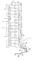
- FIG. 4 is a vertical sectional side view showing the uppermost linear feeder 5 which is the uppermost side in the transport direction of the article.
- FIG. 5 is a vertical sectional side view in which the terminal end in the transport direction is enlarged. It is the perspective view.
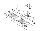
- FIG. 7 is a perspective view of the lower straight feeder 5 which is the lowermost side in the article conveying direction among the three straight feeders 5.
- Each of the linear feeders 5 of each stage has a structure including a transport trough 10 having a pair of side plates erected from both ends in the width direction of the bottom plate, and a connecting plate 11 on the lower surface of the bottom plate of the transport trough 10. ing. As shown in FIG. 4, the connection plate 11 is positioned and locked on a vibration head portion 12a of a vibrator 12, and is detachably connected by a buckle-shaped fastener 13.
- the bottom surface 10a which is the transport surface of the transport trough 10, is formed in a continuous wave shape having a pitch of, for example, about 15 mm and a depth of, for example, about 2 mm, in the transport direction (front-back direction) of the article w.
- the corrugated pitch of the bottom surface 10a is a pitch corresponding to the width of one article w such that one article w enters the corrugated recess and becomes horizontal.
- the elongated article w placed on the bottom surface 10a of the transport trough 10 is laterally oriented along the waveform by being vibrated, that is, while its longitudinal direction is aligned in an attitude orthogonal to the transport direction of the article w. , And is conveyed forward by vibration.
- the elongated article w is vibrated and conveyed by the conveying trough 10, it repeatedly passes through the corrugated concave portions and convex portions that are continuous at a constant pitch in the conveying direction, and is aligned in a horizontal posture along the corrugated shape. Conveyed.
- the transport direction of the articles w by the transport trough 10 is forward, and the arrangement direction of the plurality of weighing units 4 is the horizontal direction. Therefore, the direction orthogonal to the transport direction of the articles w is the arrangement direction of the plurality of weighing units 4. Some horizontal direction. Therefore, the article w is vibrated and conveyed by the vibration conveyance by the conveyance trough 10 while its longitudinal direction is aligned in the horizontal direction, which is the arrangement direction of the plurality of weighing units 4.
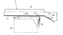
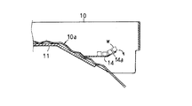
- the transport trough 10 in the upper and middle straight feeders 5 has a bottom surface 10a whose front end side is inclined forward and downward, and is provided with a movement suppressing plate 14 for suppressing the transfer movement of articles.
- the movement suppressing plate 14 of this embodiment is made of a wide flat plate material on which the article w can be stably placed in a horizontal position.
- the movement restraining plate 14 extends horizontally from the bottom surface 10a of the transport trough 10 in the transport direction, and has an inclined rising portion 14a which is slightly upwardly inclined at the front end thereof.
- the article w vibrated and conveyed on the corrugated bottom surface 10a is pushed onto the movement suppressing plate 14, and then pushed by the following article w to move on the movement suppressing plate 14, and the terminal end rises inclining.
- the movement of the article w is suppressed in the section 14a, and the article w is carried out little by little over the inclined rising section 14a by the subsequent extrusion conveyance.
- the movement suppressing plate 14 applies an appropriate conveyance resistance to the articles w in the lateral orientation, and suppresses a large amount of articles w from being sent from the end of the trough at once, and the orientation is suppressed.
- Immediately before being carried out by imparting conveyance resistance to the articles, there is also an effect of adjusting the posture of the articles that are not sufficiently aligned.
- the movement suppressing plate 14 is not limited to a flat plate shape, but may be a comb tooth shape or the like.
- a transport trough shutter 15 that can be swung up and opened around an upper fulcrum p is provided at the end of the transport trough 10 in the lower straight feeder 5 that is the final stage, as shown in FIG.
- the transport trough shutter 15 opens and closes the end of the transport path by the transport trough 10 by the air cylinder 16.
- elongated articles are collectively supplied to the transport trough 10 of the upper straight feeder 5 using a robot hand (not shown).
- the articles supplied to the upper straight feeder 5 are vibrated and conveyed sequentially to the middle straight feeder 5 and the lower straight feeder 5 to be laterally aligned.
- the vibration amplitude of the upper straight feeder 5 to which articles are supplied collectively is maximized, the vibration time is minimized, the vibration amplitude of the lower straight feeder 5 is minimized, and the vibration time is maximized.
- the articles supplied in a state of being gathered in the upper straight feeder 5 are sequentially vibrated and conveyed to the middle straight feeder 5 and the lower straight feeder 5 by an appropriate amount, and the lower straight feeder 5 disperses the articles.
- One article w can be laterally aligned such that one article w enters the corrugated depression on the bottom surface 10a of the transport trough 10.
- Each of the rectilinear feeders 5 starts driving when the articles are discharged from the supply hopper 6 and the supply hopper 6 becomes empty.
- the step between the upper straight feeder 5 and the middle straight feeder 5 and the difference between the middle straight feeder 5 and the lower straight feeder 5 are caused when the article falls and is transferred to the next straight feeder 5.
- the waveform of the bottom surface 10a of the transport trough 10 may be, for example, a sine waveform, or a sawtooth waveform with a steep rising surface facing the transport direction. .
- the collective alignment unloading section 2 below the combination weigher 1 receives the articles w discharged from the plurality of weighing hoppers 7 of the combination weigher 1 and arranges the plurality of weighing units 4 in the arrangement direction.
- a transport conveyor 21 for transporting along the horizontal direction.
- two front and rear conveyors 21 for conveying the article w to the left are provided, and each conveyor 21 is constituted by a belt conveyor.
- Each transport conveyor 21 is supported so as to be able to move back and forth along a guide rail 22 shown in FIG. 1 and is individually moved back and forth by a predetermined stroke by an actuator 23 such as an air cylinder.
- the rearward movement position of the front (right side in FIG. 3) conveyor 21 is the receiving position (a) for articles facing the discharge path forward of the weighing hopper 7.
- the forward movement position of the rear conveyor (the left side in FIG. 3) is the receiving position (a) for articles facing the discharge path behind the weighing hopper 7.
- a pair of front and rear guides 24 is provided on both sides of each conveyor 21 in the width direction so as to extend upward along the conveyance path.
- the guides 24 guide the articles w discharged from the weighing hopper 7 onto the belt without spilling.
- a plurality of collective troughs 25 into which the articles w discharged from the respective conveyors 21 are placed are arranged on the lower side of the conveyor 21 in the conveying direction.
- each collecting trough 25 is located at a receiving position (a) where each conveyor 21 receives the articles discharged from the weighing hopper 7, and at a retracting position (b) outside the receiving position.
- the four conveyors 21 are provided in a line in front and rear so as to face the end of each conveyor 21 at the time.
- the articles discharged from the weighing hopper 7 of the combination weigher 1 are transported by the two transport conveyors 21 at the receiving position (a) or the retreat position (b), and the four collective troughs are transported along four transport paths. 25.
- the conveyor 21 is driven for a certain time when the articles are put into the collecting trough 25.
- FIG. 8 is a longitudinal sectional view of the collecting and sorting unit 2
- FIG. 9 is a perspective view of the collecting trough 25 of the collecting and sorting unit 2
- FIG. 10 is a front view of the collecting trough 25.
- the collective trough 25 into which articles are input from the conveyor 21 has a concave and curved bottom, and a trough body 25a having an open U-shaped cross section is surrounded by a support plate 25b and reinforced. It has a supported structure.
- the trough main body 25a is embossed to reduce friction with an article.
- the support plate 25b has a structure in which a pair of side plates are erected from both ends in the width direction of the bottom plate.
- the connecting table 25c connected to the lower surface of the support plate 25b is positioned and locked on the vibration head 26a of the vibrator 26, and is detachably connected by a buckle-shaped fastener 27.
- a pusher 33 that can move forward and backward in the longitudinal direction of the trough by the air cylinder 32 is provided on the inner back of each of the collective troughs 25.
- a long and narrow article w is supplied to the starting end of the straight-line feeder 5 in the conveying direction in the conveying direction of the aligning and conveying device 3 using a robot hand or the like (not shown).
- the article w supplied to the start end of the upper straight feeder 5 is first subjected to the vibration conveying action of the straight feeder 5, and is aligned with the wave shape of the bottom surface 10a of the transfer trough 10, that is, while being aligned in the horizontal position, Sent to The article w which has reached the terminal end of the transport trough 10 of the upper straight feeder 5 is transferred to the middle straight feeder 5 over the movement suppressing plate 14 while maintaining the horizontal posture. Similarly, the middle straight feeder 5 is sent forward while being aligned in a horizontal position along the corrugation of the bottom surface 10a of the transport trough 10, and is sent into the lower straight feeder 5.
- the sheet is fed forward while being aligned in the horizontal position, and is received and held by the transport trough shutter 15.
- the transport trough shutter 15 is controlled to open for a predetermined time, and a small amount of articles is supplied to the supply hopper 6 in a horizontal position. Then, when the articles w are discharged from the weighing hopper 7 weighed by the weighing hopper 7 and selected as a proper combination by the combination calculation and become empty, the supply hopper 6 is opened and a new article w is supplied to the weighing hopper 7. You.
- Either one of the gates 7a, 7b (7b) of the plurality of weighing hoppers 7 selected in the proper amount combination within the predetermined weight range by the combination operation is selectively opened and controlled, and the article w having the predetermined weight range is moved forward or forward. It is dropped and discharged to the rear discharge path.
- the alignment state of the plurality of articles w dropped and discharged from the weighing hopper 7 is not largely collapsed, and the articles w are dropped and discharged in a substantially horizontal posture.
- the articles w discharged from the weighing hopper 7 are dropped and supplied at a plurality of locations in the transport direction of the transport conveyor 21 located at the receiving position (a) with the longitudinal direction of the articles in a horizontal position substantially along the transport direction of the transport conveyor 21. Is done.
- the conveyor 21 having received the article w selects either the receiving position (a) or the retreat position (b) as the article unloading position according to the condition of the collecting trough 25, and moves forward and backward for each conveyor 21.
- the transport is performed toward the collective trough 25 arranged corresponding to the two systems of unloading positions.
- the entire amount of the articles w discharged from the weighing hopper 7 and dropped and supplied to a plurality of locations in the transport direction of the transport conveyor 21 is thrown into the collective trough 25, so that the articles w of a predetermined weight range are carried into the collective trough 25. Will be accommodated.
- each transport conveyor 21 also basically alternately carries out articles in a predetermined weight range to the collecting trough 25 corresponding to the receiving position (a) and the collecting trough 25 corresponding to the retreat position (b). .
- the articles w in the predetermined weight range put into the collective trough 25 are subjected to a vibrating and conveying action in a posture along the longitudinal direction of the concave and curved bottom surface, conveyed while being aligned in parallel with each other, and received by the collective trough shutter 29. Can be stopped.
- the pusher 33 is retracted to a position where the loading of the articles is not hindered.
- the pusher 33 repeats advancing and retreating to the predetermined position (c) shown in FIG. 8 a predetermined number of times at a low speed, and taps the rear end of the article w being subjected to the vibration conveyance action.
- the predetermined position (c) at which the rear end of the articles w is aligned and the pusher 33 waits is a position slightly behind the rear end position of the articles w received and stacked by the collective trough shutter 29. Therefore, the rear end of the article w received by the collective trough shutter 29 is not forcibly pressed.
- the articles w discharged from the four collecting troughs 25 are conveyed to the packaging step by appropriate means.
- a tray-shaped carrier supported by a robot arm or the like is made to stand by at a discharge point of the collective trough 25, and the articles w discharged in an aligned state from the collective trough 25 are received by the carrier.
- the transporting tool is moved to the conveyor line of the packaging container, the articles are transferred and loaded from the transporting tool to the packaging container that is transported at a constant pitch, and then the packaging container containing the article is sent to the sealing process. , Etc. are performed.
- the conveyor 21 is configured to be reversible. For example, when an excessive amount of articles that are difficult to be selected as an appropriate combination is supplied to the weighing hopper 7, the excessive amount of articles is discharged from the weighing hopper 7 to the transport conveyor 21, and the transport conveyor 21 is driven in reverse. Thereby, the excessive amount of articles is discharged to the collection box 35 shown in FIG.
- the articles w are aligned by the three-stage rectilinear feeders 5 so that the longitudinal direction thereof is along the horizontal direction which is the arrangement direction of the plurality of weighing units 4. It can be supplied to the supply hopper 6.
- the shape of the bottom surface of the transport trough 10 constituting the straight-ahead feeder 5 in the aligning and transporting device 3 is not limited to the corrugated shape as long as it can guide and guide the elongated articles in the horizontal direction and can pass over them.
- each transport trough 10 in the plurality of linear feeders 5 arranged along the transport direction of the articles may be different for each linear feeder 5.
- the corrugated pitch and height of the bottom surface 10a of the transport trough 10 of the straight-line feeder 5 on the upstream side in the article transport direction are increased, and the bottom surface 10a of the transport trough 10 of the straight-line feeder 5 on the downstream side in the article transport direction is increased.
- the pitch and height of the corrugations may be reduced, or the like, so that the alignment function and the transport function are different for each straight-ahead feeder 5.
- the number of the linear feeders 5 constituting the alignment supply unit 3 is not limited to three, but may be less than three or four or more.
- the aligning and transporting device 3 of the present invention is suitable for aligning and transporting articles such as relatively soft and elongated cheese cod, but can also be applied to aligning and transporting relatively hard and elongated articles such as stick pans. it can.
Landscapes
- Engineering & Computer Science (AREA)
- Mechanical Engineering (AREA)
- Physics & Mathematics (AREA)
- General Physics & Mathematics (AREA)
- Feeding Of Articles To Conveyors (AREA)
- Jigging Conveyors (AREA)
- Intermediate Stations On Conveyors (AREA)
Abstract
比較的柔らかくて細長い物品(w)を、曲げたり、折ったりすることなく、整列させた状態で搬出することができる整列搬送装置(3)を提供する。物品(w)の搬送方向に沿って配置された複数の搬送トラフ(10)を備え、各搬送トラフ(10)を振動駆動して、搬送方向の最も上手側の搬送トラフ(10)に供給される物品(w)を、搬送方向に振動搬送しながら整列させる。
Description
本発明は、物品を整列させながら搬送する整列搬送装置に係り、特には、比較的柔らかくて細長い物品を整列させながら搬送するのに好適な整列搬送装置に関する。
物品を整列させながら搬送する装置として、例えば、特許文献1に記載されているものがある。この特許文献1の装置では、円形フィーダによって分散搬送した細長い棒状の物品を、直進フィーダによって振動搬送して、中間ホッパ及び計量ホッパに供給するものである。前記直進フィーダの搬送面には、物品の搬送方向と直交する複数の整列用片を、適当間隔をもって設け、物品を整列用片と平行となる姿勢に整列させるようにしている。
特許文献1は、多少の衝撃によって曲がったり折れたりすることのない硬めの棒状物品を対象とするものであり、例えば、鱈のすり身を主原料とする乾燥シートの間にチーズを挟んで細長く切断したチーズタラあるいはジャーキー等の比較的柔らかくて細長い物品に適用すると、十分に整列させることなく搬出してしまいやすいものであった。
本発明は、このような実情に着目してなされたものであって、比較的柔らかくて細長い物品を整列させながら搬送することができる整列搬送装置を提供することを目的とする。
上記目的を達成するために、本発明では次のように構成している。
(1)本発明に係る整列搬送装置は、物品の搬送方向に沿って配置された複数の搬送トラフを備え、各搬送トラフを振動駆動して、前記搬送方向の最も上手側の前記搬送トラフに供給される前記物品を、前記搬送方向に振動搬送しながら整列させる。
本発明によると、物品を振動搬送しながら、搬送方向に沿って配置された複数の搬送トラフによって、段階的に整列状態を整えることができ、搬送方向の最も下手側の搬送トラフでは、物品を、良好な整列状態にすることができる。これによって、例えば、チーズタラやジャーキー等の比較的柔らかくて細長い物品であっても、曲がったり折れたりすることなく、整列させることができる。
(2)本発明の好ましい実施態様では、前記搬送トラフの搬送面は、前記搬送方向に一定ピッチで連続する波型である。
ここで、波型とは、凸部と凹部が交互に繰り返す形状をいう。凸部及び凹部の形状は、円弧状、三角形状や四角形状など任意である。
この実施態様によると、細長い物品は、搬送トラフによって振動搬送されながら、搬送方向に一定ピッチで連続する波型の凹部と凸部とを繰り返し通過することで、波型に沿った横向き姿勢、すなわち、物品の長手方向が搬送方向に直交する姿勢に整列されて搬送される。
(3)本発明の他の実施態様では、前記複数の搬送トラフの内、前記搬送方向の最も下手側の搬送トラフの搬送路を開閉するシャッタを有し、前記シャッタは、前記最も下手側の前記搬送トラフにおける前記搬送方向の終端に設けられる。
この実施態様によると、物品の搬送方向の最も下手側の搬送トラフの搬送終端に至った物品は、シャッタに沿った横向き姿勢で受止められながら振動を受け、振動を受ける間に、より整った整列状態となる。シャッタの開放に伴って横向き姿勢の整った整列状態の物品が搬出される。
(4)本発明の更に他の実施態様では、前記複数の搬送トラフの内、前記最も下手側の搬送トラフ以外の搬送トラフは、前記搬送方向の終端部に、物品の搬送移動を抑制する移動抑制部材を有する。
この実施態様によると、移動抑制部材は、適度の搬送抵抗を物品に与えて、搬送トラフ終端から多量の物品が一挙に搬出されて姿勢が崩れるのを抑制することができる。また、搬出される直前に、物品に適度の搬送抵抗を与えることによって、整列が不十分な物品の姿勢を整える効果もある。
(5)本発明の他の実施態様では、前記移動抑制部材は、前記搬送トラフの前記波型の搬送面から前記搬送方向に延出され、かつ、その先端側が上方へ傾斜している。
この実施態様によると、移動抑制部材の先端側の上方への傾斜角度や搬送方向での長さを適宜選択することによって、搬送移動する物品に与える搬送抵抗を調整することができる。これによって、物品の搬送方向の上手側の搬送トラフから下手側の搬送トラフへ所望量の物品を搬出することができる。
(6)本発明の更に他の実施態様では、前記物品を振動搬送して、組合せ秤の計量ユニットに供給する。
この実施態様によると、比較的柔らかくて細長い物品を、整列させた状態で組合せ秤に供給して組合せ計量することができる。
本発明によれば、比較的柔らかくて細長い物品を、曲げたり、折ったりすることなく整列させた状態で搬出することができる。
以下、本発明の実施形態について、図面を参照しながら詳細に説明する。
図1は、本発明の一実施形態に係る整列搬送装置を備える組合せ計量装置の斜視図であり、図2は、図1の組合せ計量装置を模式的に示す概略正面図であり、図3は、図1の組合せ計量装置を模式的に示す概略側面図である。
なお、以下においては、説明の便宜上、図2における左右方向、及び、図3における紙面表裏方向を左右方向と呼称し、図2における紙面表裏方向、及び、図3における左右方向を前後方向と呼称することにする。
この実施形態の組合せ計量装置は、例えば、鱈のすり身を主原料とする乾燥シートの間にチーズを挟んで細長く切断したチーズタラあるいはジャーキーなどの比較的柔らかくて細長い物品を計量して搬出するのに好適な組合せ計量装置である。この組合せ計量装置は、チーズタラ等の物品を組合せ計量して排出する組合せ秤1と、組合せ秤1から排出された物品を横一側方(この例では左方)へ搬送すると共に、集合整列させて搬出する集合整列搬出部2とを備えている。
上部に配置されている組合せ秤1は、物品を左右方向に並列した多数系統、この例では14系統の整列搬送径路で前方へ搬送しながら整列させる整列搬送装置3と、整列搬送装置3の各整列搬送径路から搬送されてきた物品を受け取るように、一方向、この例では、横方向に沿って並んで配置された多数連(この例では14連)の計量ユニット4とを備えている。
この実施形態の整列搬送装置3における一つの整列搬送径路は、3台の直進フィーダ5を、物品の搬送方向に沿って前下がり階段状に縦列配置して構成されている。各整列搬送径路で搬送された物品は、対応する各計量ユニット4にそれぞれ供給される。
各計量ユニット4は、整列搬送装置3における各整列搬送径路で搬送されてきた物品を受け取って収容保持する供給ホッパ6と、供給ホッパ6から排出された物品wを受け取ってその重量を計測する計量ホッパ7とを備えている。この実施形態では、各ホッパ6,7は、図示していないが、物品との摩擦を低減するためにエンボス加工が施されている。
組合せ秤1では、従来と同様に組合せ計量を行う。すなわち、組合せ秤1の制御装置(図示せず)は、複数の計量ホッパ7で計量された物品の重量を種々に組合せた組合せ重量が、目標組合せ重量に等しい又は目標組合せ重量に最も近い所定重量範囲となる計量ホッパ7の組合せである適量組合せを選択する組合せ演算を行う。この組合せ演算で適量組合せとして選択した計量ホッパ7の物品wを下方へ排出する。
計量ホッパ7には、図3に示すように、それぞれ独立に互いに反対方向に開閉する前後一対のゲート7a,7bが備えられている。これらゲート7a,7bのいずれか一方7a(7b)を、選択して開放作動させることによって、保持した物品を前後2系統の径路で排出できるようになっている。
図4~図7は、整列搬送装置3を構成する直進フィーダ5の構造を示す図である。3台の直進フィーダ5の内、上段及び中段の直進フィーダ5の構造は同じであるので、図4~図6では、上段の直進フィーダ5を代表的に示す。また、図6,図7及び後述の図9では、1個の物品wのみを代表的に示している。
図4は、物品の搬送方向の最も上手側である上段の直進フィーダ5を示す縦断側面図であり、図5は、その搬送方向の終端部を拡大した縦断側面図であり、図6は、その斜視図である。図7は、3台の直進フィーダ5の内、物品の搬送方向の最も下手側である下段の直進フィーダ5の斜視図である。
各段の直進フィーダ5は、いずれも底板の幅方向の両端から一対の側板がそれぞれ立設された搬送トラフ10と、この搬送トラフ10の底板の下面に連結板11とを備えた構造となっている。この連結板11を、図4に示すように、加振機12の振動ヘッド部12aに位置決め係止して、バックル形の締結具13で脱着可能に連結するようになっている。
また、搬送トラフ10の搬送面である底面10aは、物品wの搬送方向(前後方向)に、ピッチが例えば、15mm程度、深さが例えば、2mm程度の連続した波型に形成されている。この底面10aの波型のピッチは、1個の物品wが波型の窪みに入り込んで横向きとなるように、1個の物品wの幅に対応したピッチとなっている。
搬送トラフ10の底面10aに載置された細長い物品wは、加振されることによって波型に沿った横向き姿勢、すなわち、その長手方向が、物品wの搬送方向に直交する姿勢に整列されながら、前方に振動搬送されるようになっている。つまり、細長い物品wは、搬送トラフ10によって振動搬送されながら、搬送方向に一定ピッチで連続する波型の凹部と凸部とを繰り返し通過することで、波型に沿った横向き姿勢に整列されて搬送される。
搬送トラフ10による物品wの搬送方向は、前方であり、複数の計量ユニット4の配列方向は横方向であるので、物品wの搬送方向に直交する方向は、複数の計量ユニット4の配列方向である横方向となる。したがって、搬送トラフ10による振動搬送によって、物品wは、その長手方向が複数の計量ユニット4の配列方向である横方向に整列されながら振動搬送される。
上段及び中段の直進フィーダ5における搬送トラフ10は、その底面10aの先端側が、前下がり傾斜されると共に、物品の搬送移動を抑制する移動抑制板14が設けられている。この実施形態の移動抑制板14は、物品wを横向き姿勢で安定載置できる幅広の平板材からなる。この移動抑制板14は、搬送トラフ10の底面10aから搬送方向に水平に延出され、その先端部に、上方に向けて少し起立傾斜された傾斜立上がり部14aを備えている。
従って、波型の底面10aで振動搬送されてきた物品wは、移動抑制板14上に押し込まれた後、後続の物品wに押されて移動抑制板14上を移動し、終端部の傾斜立上がり部14aにおいて移動が抑制され、引き続く押出し搬送によって物品wは傾斜立上がり部14aを乗り越えて少量ずつ搬出されてゆく。このように、移動抑制板14は、適度の搬送抵抗を横向き姿勢の物品wに与えて、トラフ終端から多量の物品wが一挙に送出されて姿勢が崩れるのを抑制する。また、搬出される直前に、物品に搬送抵抗を与えることによって、整列が不十分な物品の姿勢を整える効果もある。
なお、移動抑制板14は、平板状に限らず、櫛歯状などであってもよい。
最終段である下段の直進フィーダ5における搬送トラフ10の先端部には、図7に示すように、上方の支点p周りに振り上げ開放可能な搬送トラフ用シャッタ15が配備されている。この搬送トラフ用シャッタ15は、エアシリンダ16によって搬送トラフ10による搬送路の終端を開閉する。
この実施形態では、上段の直進フィーダ5の搬送トラフ10に、図示しないロボットハンド等を用いて細長い物品が、纏まって供給される。この上段の直進フィーダ5に供給された物品を、振動搬送して中段の直進フィーダ5及び下段の直進フィーダ5へ順次振動搬送して横向きに整列させる。
この実施形態では、物品が纏めて供給される上段の直進フィーダ5の振動振幅を最も大きく、振動時間を最も短くし、下段の直進フィーダ5の振動振幅を最も小さく、振動時間を最も長くしている。
これによって、上段の直進フィーダ5に纏まった状態で供給された物品を、中段の直進フィーダ5及び下段の直進フィーダ5へ順次適量ずつ振動搬送し、下段の直進フィーダ5では、物品がばらけ、搬送トラフ10の底面10aの波型の窪みに1個の物品wが入り込むように横向きに整列させることができる。
各直進フィーダ5は、供給ホッパ6から物品が排出されて、供給ホッパ6が空になると、駆動が開始される。
上段の直進フィーダ5と中段の直進フィーダ5との段差、及び、中段の直進フィーダ5と下段の直進フィーダ5との段差は、物品が落下して次段の直進フィーダ5へ移載される際に、整列状態が崩れるのを抑制するために、小さい方が好ましい。
なお、搬送トラフ10の底面10aの波型は、例えば、サイン波状の波型であってもよく、あるいは、急傾斜の立ち上がり面を搬送方向に向けた鋸歯状の波型などであってもよい。
組合せ秤1の下方の集合整列搬出部2は、図1~図3に示すように、組合せ秤1の複数の計量ホッパ7から排出された物品wを受け取って、複数の計量ユニット4の配列方向である横方向に沿って搬送する搬送コンベヤ21を備えている。この例では、物品wを左方へ搬送する搬送コンベヤ21が、図3に示すように、前後2台備えられており、各搬送コンベヤ21は、ベルトコンベヤで構成されている。
搬送コンベヤ21の搬送方向の下手側に、図2に示すように、搬送コンベヤ21から排出される物品wが投入される集合トラフ25及び加振機26等を備えている。
各搬送コンベヤ21は、図1に示されるガイドレール22に沿って前後移動可能に支持されると共に、エアシリンダなどのアクチュエータ23によって所定のストロークでそれぞれ個別に前後移動されるようになっている。
図3に示すように、前側(図3の右側)の搬送コンベヤ21の後方移動位置は、計量ホッパ7の前方への排出径路に臨む物品の受取り位置(a)である。また、後側(図3の左側)の搬送コンベヤ21の前方移動位置は、計量ホッパ7の後方への排出径路に臨む物品の受取り位置(a)となっている。
各搬送コンベヤ21の幅方向の両側には、搬送径路に沿う前後一対のガイド24がそれぞれ上拡がりに立設されている。これらガイド24によって、計量ホッパ7から排出された物品wをこぼすことなくベルト上に案内するようになっている。
搬送コンベヤ21の搬送方向の下手側には、各搬送コンベヤ21から排出される物品wが投入される複数の集合トラフ25が配置されている。
各集合トラフ25は、図3に示すように、各搬送コンベヤ21が、計量ホッパ7から排出される物品を受取る受取り位置(a)と、これから外れた退避位置(b)とに、それぞれ在るときの各搬送コンベヤ21の終端に臨むように、前後一列状に4つ設けられている。
したがって、組合せ秤1の計量ホッパ7から排出された物品が、受取り位置(a)あるいは退避位置(b)にある2台の搬送コンベヤ21によって搬送されて、4系統の搬送径路で4つの集合トラフ25にそれぞれ投入される。
搬送コンベヤ21は、集合トラフ25に物品を投入するときに、一定時間駆動される。
図8は、集合整列搬出部2の縦断面図であり、図9は、集合整列搬出部2の集合トラフ25の斜視図であり、図10は、集合トラフ25の正面図である。
搬送コンベヤ21から物品が投入される集合トラフ25は、窪んで湾曲した下窄まりの底部を有し、上方が開放した断面形状がU字状のトラフ本体25aを、支持板25bで取り囲んで補強支持した構造となっている。この実施形態では、トラフ本体25aには、図示していないが、物品との摩擦を低減するためにエンボス加工が施されている。
支持板25bは、底板の幅方向の両端から一対の側板が立設された構造となっている。この支持板25bの下面に連結した連結台25cを加振機26の振動ヘッド部26aに位置決め係止して、バックル形の締結具27で脱着可能に連結するようになっている。
集合トラフ25の搬送方向の先端部には、支持板25bに連設された縦向きのレール部28が互いに内向きに対向して配備されている。この対向するレール部28に、集合トラフ用シャッタ29が上下動可能に案内支持されている。集合トラフ用シャッタ29は、図8に示すように、トラフ上方において縦姿勢で固定配備されたエアシリンダ30にステー31を介して連結されている。この集合トラフ用シャッタ29によって、集合トラフ25における搬送路が昇降開閉される。この集合トラフ用シャッタ29によって、搬送コンベヤ21から投入される物品wの先端を受け止めることができる。
集合トラフ25による振動搬送作用と、集合トラフ用シャッタ29とによる塞き止め作用とによって、集合した物品wが、その先端を揃えて整列させられる。
また、各集合トラフ25の内側背部には、エアシリンダ32によってトラフ長手方向に進退移動可能なプッシャー33が備えられている。
次に、整列搬送装置3を備える組合せ計量装置の動作を説明する。
整列搬送装置3における上段の直進フィーダ5の搬送方向の始端には、図示しないロボットハンド等を用いて細長い物品wが、適時供給される。
上段の直進フィーダ5の始端に供給された物品wは、先ず、直進フィーダ5の振動搬送作用を受け、搬送トラフ10の底面10aの波型に沿った姿勢、つまり、横向き姿勢に整列されながら前方へ送られる。上段の直進フィーダ5の搬送トラフ10の終端部に到達した物品wは、横向き姿勢を保ちながら移動抑制板14を乗り越えて中段の直進フィーダ5に移載される。中段の直進フィーダ5においても同様に搬送トラフ10の底面10aの波型に沿った横向き姿勢に整列されながら前方へ送られて下段の直進フィーダ5に送り込まれる。
下段の直進フィーダ5においては、横向き姿勢に整列されながら前方へ送られて、搬送トラフ用シャッタ15に受止め保持される。
計量ユニット4における供給ホッパ6が空になると、搬送トラフ用シャッタ15が所定時間だけ開放制御され、少量の物品が横向き姿勢で供給ホッパ6に供給される。そして、計量ホッパ7で計量され、組合せ演算によって適量組合せとして選択された計量ホッパ7から物品wが排出されて空になると、供給ホッパ6が開放されて計量ホッパ7へ新たな物品wが供給される。
組合せ演算によって所定重量範囲の適量組合せに選択された複数の計量ホッパ7におけるゲート7a、7bのいずれか一方7a(7b)が選択的に開放制御され、所定重量範囲となる物品wが、前方あるいは後方の排出径路に落下排出される。計量ホッパ7から落下排出される複数の物品wの整列状態は大きく崩れておらず、略横向き姿勢のまま落下排出される。
計量ホッパ7から物品が落下排出される時には、計量ホッパ7からの物品の排出経路である前側及び後側の搬送コンベヤ21の少なくともいずれか一方の搬送コンベヤ21が、物品の受取り位置(a)に在る。計量ホッパ7から排出された物品wは、受取り位置(a)に在る搬送コンベヤ21における搬送方向の複数個所に、物品長手方向が、搬送コンベヤ21の搬送方向に略沿った横向き姿勢で落下供給される。
物品wを受け取った搬送コンベヤ21は、集合トラフ25の状況に応じて、受取り位置(a)、あるいは、退避位置(b)のいずれかを物品の搬出位置として選択し、搬送コンベヤ21毎に前後2系統の搬出位置に対応して配置された集合トラフ25に向けての搬送が行われる。計量ホッパ7から排出されて、搬送コンベヤ21の搬送方向の複数個所に落下供給された物品wの全量が、集合トラフ25に投入されることで、集合トラフ25に所定重量範囲の物品wが搬入収容されることになる。
基本的には、計量ホッパ7からの所定重量範囲の物品の排出は、前側の搬送コンベヤ21及び後側の搬送コンベヤ21に対して交互に行われる。また、各搬送コンベヤ21による、受取り位置(a)に対応する集合トラフ25、及び、退避位置(b)に対応する集合トラフ25に対する所定重量範囲の物品の搬出も基本的には交互に行われる。
以上の動作が4つの集合トラフ25における物品排出状況に応じて繰り返される。これによって、前後2台の搬送コンベヤ21による4つの集合トラフ25への物品搬送が順次に実行される。
集合トラフ25に投入された所定重量範囲の物品wは、窪んで湾曲した底面の長手方向に沿った姿勢で振動搬送作用を受け、互いに平行に整列されながら搬送され、集合トラフ用シャッタ29に受止められる。また、搬送コンベヤ21からの物品投入時点では、プッシャー33は、物品投入を妨げない位置に退避している。物品投入が完了すると、プッシャー33は、低速で、図8に示される所定位置(c)までの進出と後退を所定回数繰り返し、振動搬送作用を受けている物品wの後端を軽くたたくように押圧して後端揃えを行って前記所定位置(c)で待機する。なお、物品wの後端揃えを行ってプッシャー33が待機する所定位置(c)は、集合トラフ用シャッタ29で受止められて積層された物品wの後端位置よりも若干後方の位置であり、集合トラフ用シャッタ29で受止められた物品wの後端を無理に押圧するようなことはない。
集合トラフ用シャッタ29が開放されると、これに連動してプッシャー33が前記待機位置から更に高速で進出作動し、整列された所定重量範囲の物品wを一挙に集合トラフ25から押出し排出する。
なお、4つの集合トラフ25から排出される物品wは、適宜手段によって包装工程に搬送される。例えば、集合トラフ25の排出箇所に、ロボットアーム等に支持されたトレー状の搬送具を待機させ、集合トラフ25から整列状態で排出された物品wを搬送具で受け取る。次に、搬送具を包装容器のコンベヤラインに移動させ、一定ピッチで搬送されてくる包装容器に搬送具から物品を移載装填し、その後、物品が収容された包装容器を封止工程に送る、等の処理がなされる。
前記搬送コンベヤ21は、逆転可能に構成されている。例えば、計量ホッパ7に、適量組合せに選択されにくい過量の物品が供給されたような場合には、その計量ホッパ7から過量の物品を搬送コンベヤ21に排出し、搬送コンベヤ21を逆転駆動する。これによって、過量の物品を、図1に示される、集合トラフ25とは反対側に配置された回収ボックス35へ排出する。
本実施形態の整列搬送装置3では、3段の直進フィーダ5によって、物品wを、その長手方向が、複数の計量ユニット4の配列方向である横方向に沿うように整列させて計量ユニット4の供給ホッパ6に供給することができる。
[その他の実施形態]
本発明は、以下のような形態で実施することもできる。
本発明は、以下のような形態で実施することもできる。
(1)整列搬送装置3における直進フィーダ5を構成する搬送トラフ10の底面形状は、細長い物品を横向きに整列案内すると共に、乗り越え通過できるものであれば、波型に限らない。
(2)物品の搬送方向に沿って配置された複数の直進フィーダ5における各搬送トラフ10の底面を、直進フィーダ5毎に異ならせてもよい。例えば、物品の搬送方向の上手側の直進フィーダ5の搬送トラフ10の底面10aの波型のピッチと高さを大きく、物品の搬送方向の下手側の直進フィーダ5の搬送トラフ10の底面10aの波型のピッチと高さを小さくする、等して、整列機能と搬送機能を直進フィーダ5毎に異ならせるようにしてもよい。
(3)整列供給部3を構成する直進フィーダ5は3台に限らず、3台未満あるいは4台以上であってもよい。
(4)本発明の整列搬送装置3は、比較的柔らかくて細長いチーズタラのような物品の整列搬送に好適であるが、スティックパンのような比較的硬く細長い物品の整列搬送にも適用することができる。
1 組合せ秤
3 整列搬送装置
4 計量ユニット
5 直進フィーダ
6 供給ホッパ
7 計量ホッパ
10 搬送トラフ
10a 底面
14 移動抑制板
14a 傾斜立上がり部
15 搬送トラフ用シャッタ
3 整列搬送装置
4 計量ユニット
5 直進フィーダ
6 供給ホッパ
7 計量ホッパ
10 搬送トラフ
10a 底面
14 移動抑制板
14a 傾斜立上がり部
15 搬送トラフ用シャッタ
Claims (6)
- 物品の搬送方向に沿って配置された複数の搬送トラフを備え、各搬送トラフを振動駆動して、前記搬送方向の最も上手側の前記搬送トラフに供給される前記物品を、前記搬送方向に振動搬送しながら整列させる、
整列搬送装置。 - 前記搬送トラフの搬送面は、前記搬送方向に一定ピッチで連続する波型である、
請求項1に記載の整列搬送装置。 - 前記複数の搬送トラフの内、前記搬送方向の最も下手側の搬送トラフの搬送路を開閉するシャッタを有し、
前記シャッタは、前記最も下手側の前記搬送トラフにおける前記搬送方向の終端に設けられる、
請求項2に記載の整列搬送装置。 - 前記複数の搬送トラフの内、前記最も下手側の搬送トラフ以外の搬送トラフは、前記搬送方向の終端部に、物品の搬送移動を抑制する移動抑制部材を有する、
請求項3に記載の整列搬送装置。 - 前記移動抑制部材は、前記搬送トラフの前記波型の搬送面から前記搬送方向に延出され、かつ、その先端側が上方へ傾斜している、
請求項4に記載の整列搬送装置。 - 前記物品を振動搬送して、組合せ秤の計量ユニットに供給する、
請求項1ないし5のいずれか一項に記載の整列搬送装置。
Priority Applications (2)
| Application Number | Priority Date | Filing Date | Title |
|---|---|---|---|
| JP2020526780A JP7150407B2 (ja) | 2018-06-27 | 2018-06-27 | 整列搬送装置 |
| PCT/JP2018/024379 WO2020003409A1 (ja) | 2018-06-27 | 2018-06-27 | 整列搬送装置 |
Applications Claiming Priority (1)
| Application Number | Priority Date | Filing Date | Title |
|---|---|---|---|
| PCT/JP2018/024379 WO2020003409A1 (ja) | 2018-06-27 | 2018-06-27 | 整列搬送装置 |
Publications (1)
| Publication Number | Publication Date |
|---|---|
| WO2020003409A1 true WO2020003409A1 (ja) | 2020-01-02 |
Family
ID=68986697
Family Applications (1)
| Application Number | Title | Priority Date | Filing Date |
|---|---|---|---|
| PCT/JP2018/024379 Ceased WO2020003409A1 (ja) | 2018-06-27 | 2018-06-27 | 整列搬送装置 |
Country Status (2)
| Country | Link |
|---|---|
| JP (1) | JP7150407B2 (ja) |
| WO (1) | WO2020003409A1 (ja) |
Cited By (4)
| Publication number | Priority date | Publication date | Assignee | Title |
|---|---|---|---|---|
| CN116046130A (zh) * | 2021-10-28 | 2023-05-02 | 株式会社石田 | 物品处理装置 |
| JP2023116186A (ja) * | 2022-02-09 | 2023-08-22 | 花王株式会社 | 物品搬送装置及び物品搬送方法 |
| JP2023148291A (ja) * | 2022-03-30 | 2023-10-13 | 大和製衡株式会社 | 均し装置及びそれを備えた組合せ計量装置 |
| JP2024031448A (ja) * | 2022-08-26 | 2024-03-07 | 大和製衡株式会社 | 組合せ計量装置 |
Citations (5)
| Publication number | Priority date | Publication date | Assignee | Title |
|---|---|---|---|---|
| JPH057452A (ja) * | 1991-07-02 | 1993-01-19 | Nippon Fillester Co Ltd | 魚体の整列装置 |
| JPH11116032A (ja) * | 1997-10-09 | 1999-04-27 | Kao Corp | 物品切出装置 |
| JP2007297160A (ja) * | 2006-04-28 | 2007-11-15 | Tokyo Shisetsu Kogyo Kk | 振動コンベア |
| JP2009174885A (ja) * | 2008-01-22 | 2009-08-06 | Anritsu Sanki System Co Ltd | 組合せ計量装置 |
| JP2010032285A (ja) * | 2008-07-28 | 2010-02-12 | Ishida Co Ltd | 計量装置 |
Family Cites Families (1)
| Publication number | Priority date | Publication date | Assignee | Title |
|---|---|---|---|---|
| JP3198972U (ja) * | 2015-05-20 | 2015-07-30 | 株式会社イシダ | 搬送装置とそれを使用した組合せ計量装置 |
-
2018
- 2018-06-27 WO PCT/JP2018/024379 patent/WO2020003409A1/ja not_active Ceased
- 2018-06-27 JP JP2020526780A patent/JP7150407B2/ja active Active
Patent Citations (5)
| Publication number | Priority date | Publication date | Assignee | Title |
|---|---|---|---|---|
| JPH057452A (ja) * | 1991-07-02 | 1993-01-19 | Nippon Fillester Co Ltd | 魚体の整列装置 |
| JPH11116032A (ja) * | 1997-10-09 | 1999-04-27 | Kao Corp | 物品切出装置 |
| JP2007297160A (ja) * | 2006-04-28 | 2007-11-15 | Tokyo Shisetsu Kogyo Kk | 振動コンベア |
| JP2009174885A (ja) * | 2008-01-22 | 2009-08-06 | Anritsu Sanki System Co Ltd | 組合せ計量装置 |
| JP2010032285A (ja) * | 2008-07-28 | 2010-02-12 | Ishida Co Ltd | 計量装置 |
Cited By (6)
| Publication number | Priority date | Publication date | Assignee | Title |
|---|---|---|---|---|
| CN116046130A (zh) * | 2021-10-28 | 2023-05-02 | 株式会社石田 | 物品处理装置 |
| JP2023116186A (ja) * | 2022-02-09 | 2023-08-22 | 花王株式会社 | 物品搬送装置及び物品搬送方法 |
| JP7813597B2 (ja) | 2022-02-09 | 2026-02-13 | 花王株式会社 | 物品搬送装置及び物品搬送方法 |
| JP2023148291A (ja) * | 2022-03-30 | 2023-10-13 | 大和製衡株式会社 | 均し装置及びそれを備えた組合せ計量装置 |
| JP7825925B2 (ja) | 2022-03-30 | 2026-03-09 | 大和製衡株式会社 | 均し装置及びそれを備えた組合せ計量装置 |
| JP2024031448A (ja) * | 2022-08-26 | 2024-03-07 | 大和製衡株式会社 | 組合せ計量装置 |
Also Published As
| Publication number | Publication date |
|---|---|
| JP7150407B2 (ja) | 2022-10-11 |
| JPWO2020003409A1 (ja) | 2021-08-12 |
Similar Documents
| Publication | Publication Date | Title |
|---|---|---|
| WO2020003409A1 (ja) | 整列搬送装置 | |
| US9463935B1 (en) | Vibratory product conveyor system | |
| US4146123A (en) | Stick aligning and conveying method and apparatus | |
| CN111971535B (zh) | 组合计量装置 | |
| CN104334026B (zh) | 食品坯料延展装置以及食品坯料延展方法 | |
| JP2003212338A5 (ja) | ||
| KR20140064773A (ko) | 물품을 처리하기 위한 방법 및 선형 장치 | |
| CN110621597A (zh) | 产品的多排传送 | |
| MX2013002610A (es) | Un ensamblaje transportador. | |
| KR101212380B1 (ko) | 분류 및 검사 장치용 슈트 | |
| JP6995456B2 (ja) | 組合せ計量装置 | |
| EP1483153B1 (en) | Placement apparatus | |
| CN201329609Y (zh) | 雪条棒捋顺机 | |
| MX2012004300A (es) | Transportador deslizable. | |
| JP6004316B2 (ja) | 少なくとも1つの物体を運搬するための移載装置及び移載方法 | |
| KR20160082966A (ko) | 로드 형상 물품을 전달하기 위한 시스템 및 방법과 컨베이어 밴드에 로드 형상 물품을 보유하기 위한 배열 및 방법 | |
| JP3379912B2 (ja) | 物品の整列供給装置 | |
| US4938338A (en) | Plastic cutlery feeder | |
| US6928789B2 (en) | Assembly for collecting together different goods | |
| JP7094645B2 (ja) | 物品整列装置 | |
| CN102038285A (zh) | 烟草加工工业的棒状制品的输送 | |
| JP6990407B2 (ja) | 供給装置および物品収容装置 | |
| JP7843486B2 (ja) | 物品集積装置、箱詰装置、及びコンテナ箱詰装置 | |
| JP2010214950A (ja) | 多くの印刷物から形成され、接着された印刷製品を製造するための方法および装置 | |
| JP6008295B2 (ja) | 食肉スライサーにおける肉片のトレー盛付装置 |
Legal Events
| Date | Code | Title | Description |
|---|---|---|---|
| 121 | Ep: the epo has been informed by wipo that ep was designated in this application |
Ref document number: 18924710 Country of ref document: EP Kind code of ref document: A1 |
|
| ENP | Entry into the national phase |
Ref document number: 2020526780 Country of ref document: JP Kind code of ref document: A |
|
| NENP | Non-entry into the national phase |
Ref country code: DE |
|
| 122 | Ep: pct application non-entry in european phase |
Ref document number: 18924710 Country of ref document: EP Kind code of ref document: A1 |