WO2020003505A1 - Fil-guide - Google Patents
Fil-guide Download PDFInfo
- Publication number
- WO2020003505A1 WO2020003505A1 PCT/JP2018/024871 JP2018024871W WO2020003505A1 WO 2020003505 A1 WO2020003505 A1 WO 2020003505A1 JP 2018024871 W JP2018024871 W JP 2018024871W WO 2020003505 A1 WO2020003505 A1 WO 2020003505A1
- Authority
- WO
- WIPO (PCT)
- Prior art keywords
- coil body
- axis
- guide wire
- wire
- end side
- Prior art date
- Legal status (The legal status is an assumption and is not a legal conclusion. Google has not performed a legal analysis and makes no representation as to the accuracy of the status listed.)
- Ceased
Links
Images







Classifications
-
- A—HUMAN NECESSITIES
- A61—MEDICAL OR VETERINARY SCIENCE; HYGIENE
- A61M—DEVICES FOR INTRODUCING MEDIA INTO, OR ONTO, THE BODY; DEVICES FOR TRANSDUCING BODY MEDIA OR FOR TAKING MEDIA FROM THE BODY; DEVICES FOR PRODUCING OR ENDING SLEEP OR STUPOR
- A61M25/00—Catheters; Hollow probes
- A61M25/01—Introducing, guiding, advancing, emplacing or holding catheters
- A61M25/09—Guide wires
-
- A—HUMAN NECESSITIES
- A61—MEDICAL OR VETERINARY SCIENCE; HYGIENE
- A61M—DEVICES FOR INTRODUCING MEDIA INTO, OR ONTO, THE BODY; DEVICES FOR TRANSDUCING BODY MEDIA OR FOR TAKING MEDIA FROM THE BODY; DEVICES FOR PRODUCING OR ENDING SLEEP OR STUPOR
- A61M25/00—Catheters; Hollow probes
- A61M25/01—Introducing, guiding, advancing, emplacing or holding catheters
- A61M25/09—Guide wires
- A61M2025/09058—Basic structures of guide wires
- A61M2025/09083—Basic structures of guide wires having a coil around a core
-
- A—HUMAN NECESSITIES
- A61—MEDICAL OR VETERINARY SCIENCE; HYGIENE
- A61M—DEVICES FOR INTRODUCING MEDIA INTO, OR ONTO, THE BODY; DEVICES FOR TRANSDUCING BODY MEDIA OR FOR TAKING MEDIA FROM THE BODY; DEVICES FOR PRODUCING OR ENDING SLEEP OR STUPOR
- A61M25/00—Catheters; Hollow probes
- A61M25/01—Introducing, guiding, advancing, emplacing or holding catheters
- A61M25/09—Guide wires
- A61M2025/09175—Guide wires having specific characteristics at the distal tip
-
- A—HUMAN NECESSITIES
- A61—MEDICAL OR VETERINARY SCIENCE; HYGIENE
- A61M—DEVICES FOR INTRODUCING MEDIA INTO, OR ONTO, THE BODY; DEVICES FOR TRANSDUCING BODY MEDIA OR FOR TAKING MEDIA FROM THE BODY; DEVICES FOR PRODUCING OR ENDING SLEEP OR STUPOR
- A61M2205/00—General characteristics of the apparatus
- A61M2205/02—General characteristics of the apparatus characterised by a particular materials
- A61M2205/0266—Shape memory materials
Definitions
- the present invention relates to a guidewire.
- a guide wire used for inserting a catheter into a blood vessel is known.
- a guide wire made of a metal coil generally includes a core shaft using a wire (wire material) and a coil body formed by winding the wire around the outside of the core shaft.
- Patent Document 1 discloses that in such a guidewire, a hydrophilic coating is applied to the surface of a coil body in order to improve the permeability of a stenotic blood vessel or a lesion.
- Patent Document 2 discloses an apparatus for manufacturing a coil body using a wire having a substantially circular cross section.
- the guide wire when the guide wire passes through the healthy part, when reaching and passing through the lesion, whether the surgeon passes through the healthy part or the lesion in the blood vessel, There was a problem that the discriminability was not sufficient. If the lesion has progressed and has become calcified, it is clear that the lesion has reached the lesion because the resistance of the guide wire is large, but for thrombus in the atheroma state, the degree of hardening of the thrombus is low. Since the guide wire can be advanced with relatively little resistance, it is necessary to improve the discriminability of reaching the lesion.
- the guide wire has a problem that when the guide wire enters a bent portion of a blood vessel, the guide wire that has entered the bent portion falls off from the bent portion in order to restore the shape due to the elasticity of the guide wire itself. Therefore, it is necessary to prevent the guide wire from falling off.
- vascular system a guide wire inserted into each organ in the human body such as a lymph gland system, a biliary system, a urinary system, an airway system, a digestive system, a secretory gland and a reproductive organ.
- a guide wire inserted into each organ in the human body such as a lymph gland system, a biliary system, a urinary system, an airway system, a digestive system, a secretory gland and a reproductive organ.
- the present invention has been made to solve the above-described problems.
- selectivity vascular selectivity
- the present invention has been made to solve at least a part of the problems described above, and can be realized as the following embodiments.
- a guidewire includes a core shaft, and a coil body formed by winding a wire around the core shaft, wherein the wire has a long axis and a short axis in a cross section,
- the coil body has an inclined portion in which an angle formed by the long axis of the strand and the axis of the coil body is an acute angle with respect to a first direction along the axis of the coil body.
- the coil body has the inclined portion in which the angle formed by the long axis of the element wire and the axis of the coil body is acute with respect to the first direction along the axis of the coil body. That is, in the inclined portion, the element wire forming the coil body is obliquely wound in the first direction. In this manner, the wire is obliquely wound, so that in the inclined portion, the corner of each wire protrudes in the second direction opposite to the first direction.
- selectivity vascular selectivity
- the coil body may further include a flat portion in which an angle formed by the long axis of the strand and an axis of the coil body is parallel.
- the coil body further has a flat portion in which the angle formed by the long axis of the strand and the axis of the coil body is parallel.
- the wire forming the coil body is wound flat with respect to the axis of the coil body, so that no projecting portion is formed on the surface of the coil body. For this reason, in the guidewire of this configuration, it is possible to improve the selectivity (blood vessel selectivity) in the inclined portion and improve the passage of a stenotic blood vessel or a lesion in the flat portion.
- the inclined portion may be disposed on a distal end side of the coil body, and the flat portion may be disposed on a proximal end side of the coil body.
- the reaction force applied to the guidewire becomes larger from the vicinity of the center to the proximal end than from the distal end in the axial direction.
- the inclined portion having a higher frictional resistance depending on the traveling direction of the guide wire is arranged on the distal end side where the reaction force applied to the guide wire is smaller, and the flat portion having a constant frictional resistance is provided. Is arranged on the base end side where the reaction force applied to the guide wire is large, thereby damaging the inner wall of a blood vessel or the like due to the guide wire.
- the element wire in the inclined portion, is closer to the distal end side of the long axis than to a distance between an end point on the base end side of the long axis and the axis. It may be wound so that the distance between the end point and the axis is reduced.
- the element wire in the inclined portion is located between the end point on the distal end side of the long axis and the axis of the coil body as compared with the distance between the end point on the base end side of the long axis and the axis of the coil body.
- the guide wire of the present configuration has a configuration in which the wire in the inclined portion is obliquely wound toward the distal end side of the coil body, and the corner of each wire protrudes toward the base end side of the coil body. Therefore, it is possible to provide a guide wire having a low frictional resistance at the time of pushing, and a high frictional resistance at the time of pulling, since the corners of the respective wires in the inclined portion are caught by the inner wall of the blood vessel or the like.
- the element wire in the inclined portion, may be closer to the distal end side of the long axis than to a distance between an end point on the base end side of the long axis and the axis. It may be wound so that the distance between the end point and the axis is long.
- the element wire in the inclined portion is located between the end point on the distal end side of the long axis and the axis of the coil body as compared with the distance between the end point on the base end side of the long axis and the axis of the coil body. Are wound so that the distance is longer, the first direction is toward the proximal end of the coil body, and the second direction is toward the distal end side of the coil body.
- the guide wire of the present configuration has a configuration in which the wire in the inclined portion is obliquely wound toward the base end side of the coil body, and the corner of each wire protrudes toward the distal end side of the coil body. For this reason, at the time of pushing, a corner portion of each element wire in the inclined portion is caught on the inner wall of a blood vessel or the like, thereby providing a guide wire having a high frictional resistance and a low frictional resistance at the time of pulling.
- a cross-sectional shape of the element wire may be a substantially elliptical shape.
- the shape of the cross section of the element wire is substantially elliptical, so that damage to the inner wall of a blood vessel or the like due to a corner protruding in the second direction can be suppressed.
- the present invention can be realized in various modes, and can be realized in the form of, for example, a coil body for a guide wire, a method for manufacturing a coil body, a method for manufacturing a guide wire, and the like.
- FIG. 3 is a partial cross-sectional view of the distal end side of the guide wire. It is the top view which expanded the front-end
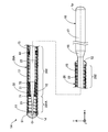
- FIG. 1 is a partial cross-sectional view illustrating the entire configuration of the guidewire 1 according to the first embodiment.
- the guide wire 1 is, for example, a medical device used when inserting a catheter into a blood vessel, and includes a core shaft 10, a coil body 20, a distal-side fixing portion 51, a proximal-side fixing portion 52, and an intermediate fixing portion 61.
- an axis passing through the center of the guidewire 1 is represented by an axis O (dashed line).
- both the axis passing through the center of the core shaft 10 and the axis passing through the center of the coil body 20 coincide with the axis O.
- the axis passing through the center of the core shaft 10 and the axis passing through the center of the coil body 20 may be different from the axis O.
- FIG. 1 illustrates XYZ axes that are orthogonal to each other.
- the X axis corresponds to the axial direction of the guidewire 1
- the Y axis corresponds to the height direction of the guidewire 1
- the Z axis corresponds to the width direction of the guidewire 1.
- the left side ( ⁇ X axis direction) of FIG. 1 is referred to as “the distal end side” of the guide wire 1 and each component
- the right side (+ X axis direction) of FIG. 1 is referred to as the “proximal side” of the guide wire 1 and each component member. Call.
- distal end or simply “distal end”
- proximal end or simply “proximal end”.
- distal side corresponds to “distal side”
- proximal side corresponds to “proximal side”.
- the core shaft 10 is a tapered long member having a large diameter at the base end and a small diameter at the front end.
- the core shaft 10 can be formed of a material such as a stainless steel alloy such as SUS304 and SUS316, a superelastic alloy such as a nickel titanium (NiTi) alloy, a piano wire, a nickel-chromium alloy, a cobalt alloy, and tungsten.
- the core shaft 10 may be formed of a known material other than the above.
- the core shaft 10 includes a small-diameter portion 11, a first reduced-diameter portion 12, a second reduced-diameter portion 13, a first large-diameter portion 15, a third reduced-diameter portion 16, and a It has two large diameter portions 17.
- the outer diameter and length of each part can be arbitrarily determined.
- the small-diameter portion 11 is disposed at the tip of the core shaft 10.
- the small-diameter portion 11 is a portion where the outer diameter of the core shaft 10 is the minimum, and has a substantially cylindrical shape having a constant outer diameter.
- the first reduced diameter portion 12 is arranged between the small diameter portion 11 and the second reduced diameter portion 13.
- the first reduced diameter portion 12 has a substantially truncated cone shape whose outer diameter is reduced from the base end side toward the distal end side.
- the second reduced diameter portion 13 is disposed between the first reduced diameter portion 12 and the first large diameter portion 15.
- the second reduced diameter portion 13 has a substantially truncated cone shape whose outer diameter is reduced from the base end side toward the distal end side.
- the first large diameter portion 15 is disposed between the second reduced diameter portion 13 and the third reduced diameter portion 16.
- the first large diameter portion 15 has a substantially cylindrical shape having a constant outer diameter larger than the outer diameter of the small diameter portion 11.
- the third reduced diameter portion 16 is disposed between the first large diameter portion 15 and the second large diameter portion 17.
- the third reduced diameter portion 16 has a substantially truncated cone shape whose outer diameter is reduced from the base end side toward the distal end side.
- the second large-diameter portion 17 is arranged at a base end of the core shaft 10.
- the second large-diameter portion 17 has a substantially cylindrical shape having a constant outer diameter larger than the outer diameter of the first large-diameter portion 15.
- the outer surfaces of the small-diameter portion 11, the first reduced-diameter portion 12, the second reduced-diameter portion 13, and the first large-diameter portion 15 are covered by a coil body 20 described later.
- the third reduced diameter portion 16 and the second large diameter portion 17 are not covered by the coil body 20 and are exposed from the coil body 20.
- the second large diameter portion 17 is used when an operator grips the guidewire 1.
- the coil body 20 has a substantially cylindrical shape formed by spirally winding an element wire around the core shaft 10.
- the coil body 20 of the present embodiment includes an inclined portion 201 disposed on the distal end side, and a flat portion 202 disposed on the proximal end side.
- the inclined portion 201 is formed using the first wire 21, and the flat portion 202 is formed using the second wire 22.
- the first strand 21 and the second strand 22 are joined with a joining agent (not shown) (FIG. 4: joint 23).
- the coil body 20 is configured as a single coil.
- the average coil diameter of the coil body 20 (the average diameter of the outer and inner diameters of the coil body 20) can be arbitrarily determined.
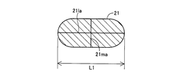
- FIG. 2 is a cross-sectional view of the first strand 21.
- the first strand 21 has a substantially elliptical cross-sectional shape having a major axis 21la and a minor axis 21ma.
- an ellipse in which the “square” portion in the known elliptic equation is a power greater than the square is also included.
- a portion having the longest length L1 in the longitudinal direction is referred to as a “long axis 21la”, and the vertical axis of the long axis 21la drawn inside the cross section is defined.
- the bisector is referred to as “short axis 21 ma”.
- the length of the major axis 21la and the length of the minor axis 21ma can be arbitrarily determined.
- the first strand 21 can be formed of, for example, a radiopaque alloy such as platinum or an alloy containing platinum (eg, a platinum-nickel alloy).
- the first strand 21 may be formed of a known material other than the above.
- the second strand 22 has a substantially elliptical cross section having a major axis and a minor axis.
- the length of the long axis and the length of the short axis of the second strand 22 can be arbitrarily determined.
- the second strand 22 is made of, for example, stainless steel alloys such as SUS304 and SUS316, superelastic alloys such as NiTi alloys, piano wires, radiolucent alloys such as nickel-chromium alloys, cobalt alloys, gold, platinum, tungsten, and the like. (For example, a platinum-nickel alloy) or a radiopaque alloy.
- the second strand 22 may be formed of a known material other than the above.
- the cross-sectional shape, the length of the major axis, the length of the minor axis, and the material of the second strand 22 may be the same as or different from the first strand 21.
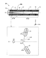
- FIG. 3 is a partial sectional view of the distal end side of the guidewire 1.
- an upper part shows a partially enlarged view of the distal end side of the guide wire 1
- a lower part shows an enlarged view of a broken frame portion of the first strand 21.
- both the angles ⁇ 11 and ⁇ 12 formed by the long axis 21la and the axis O (dashed line) of the coil body 20 are along the axis O.
- An acute angle that is, less than 90 degrees
- the “angle formed by the major axis and the axis” is defined as an extension of the major axis 21la projected on the virtual plane including the axis O and the axis O.
- the first direction DI1 along the axis O is a direction toward the distal end of the coil body 20.
- the first strand 21 in the inclined portion 201 has a longer axis 21la than the distance L12 between an end point on the base end side of the longer axis 21la and the axis O of the coil body 20.
- the distance L11 between the end point on the tip end side of the coil body 20 and the axis O of the coil body 20 is set to be shorter.
- the “distance between the end point and the axis” is defined as follows: when the major axis 21la is projected on the virtual plane including the axis O, the axis O is calculated from each end point of the major axis 21la projected on the virtual plane. Means the length of the perpendicular drawn.
- the angle formed by the long axis of the second strand 22 in the flat portion 202 and the axis O of the coil body 20 is parallel to the axis O.
- the outer diameter D1 on the distal end side and the outer diameter D11 on the proximal end side are substantially the same, but these outer diameters D1 and D11 are different. Is also good.
- the distal end side fixing portion 51 is disposed at the distal end portion of the guide wire 1 and connects the distal end portion of the core shaft 10 (the distal end portion of the small diameter portion 11) and the distal end portion of the coil body 20 (the distal end portion of the inclined portion 201). They are held together.
- the distal end side fixing portion 51 can be formed with an arbitrary bonding agent, for example, a metal solder such as silver brazing, gold brazing, zinc, Sn—Ag alloy, Au—Sn alloy, or an adhesive such as an epoxy adhesive.
- the proximal fixing portion 52 is disposed at the proximal end of the first large-diameter portion 15 of the core shaft 10, and integrates the core shaft 10 with the proximal end of the coil body 20 (the proximal end of the flat portion 202). Holding.
- the proximal fixing portion 52 can be formed of an arbitrary bonding agent, similarly to the distal fixing portion 51. The same fixing agent may be used for the proximal fixing portion 52 and the distal fixing portion 51, or different bonding agents may be used.
- the intermediate fixing portion 61 integrally holds the coil body 20 (flat portion 202) and the core shaft 10 in the vicinity of an intermediate portion of the coil body 20 in the direction of the axis O.
- the intermediate fixing portion 61 can be formed of an arbitrary bonding agent, similarly to the distal fixing portion 51.
- the same fixing agent may be used for the intermediate fixing portion 61 and the distal fixing portion 51, or different bonding agents may be used.
- FIG. 1 illustrates one intermediate fixing portion 61, the guide wire 1 may be provided with a plurality of intermediate fixing portions 61.
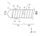
- FIG. 4 is an enlarged plan view of the distal end side of the guidewire 1.
- the first element wire 21 forming the coil body 20 is obliquely wound toward the distal end side (first direction DI1) of the coil body 20.
- the first wire 21 is obliquely wound, so that the surface of each first wire 21 (that is, the surface of the coil body 20) is formed from the distal end side (first direction DI1).
- An inclined surface 21 is inclined so as to expand toward the end side (second direction DI2) and a corner 21e protruding toward the base end side (second direction DI2) are formed.
- the “second direction DI2” is the opposite side of the first direction DI1.
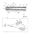
- FIG. 5 is a diagram showing an example when the guidewire 1 is used.
- FIG. 5 illustrates the guidewire 1 inserted into the blood vessel 91 in the upper part, and an enlarged view of the distal end side of the guidewire 1 (an enlarged view of a broken frame portion) in the lower part.
- the slope 21 is inclined from the distal end side (first direction DI1) to the proximal end side (second direction DI2) of the coil body 20 in the inclined portion 201. Is formed.
- the corner 21e protruding toward the base end side (the second direction DI2) of the coil body 20 is formed on the inner wall 91i of the blood vessel 91.
- the frictional resistance applied to the guide wire 1 can be increased as compared with the configuration having no inclined portion 201.
- the corners 21 e of the first wires 21 protruding toward the base end side (the second direction DI2) of the coil body 20 are hooked on the inner wall 91 i of the blood vessel 91 and the like. This makes it possible to apply different frictional resistances when the guidewire 1 is pushed (upper row in FIG. 5: white arrow) and when the guidewire 1 is pulled (lower row in FIG. 5: arrow with dot hatching). ) Can be improved.
- the coil body 20 has the flat portion 202 in which the angle formed by the long axis of the second strand 22 and the axis O of the coil body 20 is parallel.
- the flat portion 202 since the second element wire 22 forming the coil body 20 is wound flat with respect to the axis O of the coil body 20, no projecting portion is formed on the surface of the coil body 20 (FIG. 4). For this reason, in the guide wire 1 of the present embodiment, it is possible to improve the permeability of a blood vessel or a lesion that is narrowed in the flat portion 202.
- the reaction force applied to the guide wire 1 becomes larger from the vicinity of the center to the base end side than the tip side in the direction of the axis O.
- the inclined portion 201 having a higher frictional resistance depending on the traveling direction of the guide wire 1 than the flat portion 202 is arranged on the distal end side where the reaction force applied to the guide wire 1 is small. I do.
- the flat portion 202 having a constant frictional resistance is arranged on the base end side where the reaction force applied to the guide wire 1 is large. For this reason, in the guidewire 1 of the present embodiment, damage to the inner wall 91i such as the blood vessel 91 by the guidewire 1 can be suppressed.
- the first wire 21 and the second wire 22 that form the coil body 20 have a substantially elliptical cross-sectional shape, so that the proximal end side of the coil body 20 is formed. Damage to the inner wall 91i of the blood vessel 91 or the like due to the corner 21e of each first strand 21 projecting in the (second direction DI2) can be suppressed.
- the guide wire 1 of the present embodiment since a difference occurs between the resistance at the time of pushing and the resistance at the time of pulling out when the guide wire 1 passes through the lesion, it is determined whether the guide wire 1 passes through the healthy part. It is possible to improve the discriminability of whether the sheet has passed the section.
- FIG. 6 is a partial cross-sectional view illustrating the entire configuration of the guidewire 1A according to the second embodiment.
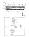
- FIG. 7 is a partial cross-sectional view of the distal end side of the guidewire 1A according to the second embodiment. 7 are the same as those in FIG.
- the guide wire 1A of the second embodiment has an inclined portion 201A in which a first element wire 21 is wound in the coil body 20A in a direction opposite to that of the first embodiment.
- both the angles ⁇ 21 and ⁇ 22 formed by the long axis 21la and the axis O (dashed line) of the coil body 20A are along the axis O.
- An acute angle (that is, less than 90 degrees) with respect to the first direction DI1.
- the first direction DI1 is opposite to that of the first embodiment, that is, the direction toward the base end of the coil body 20A.
- the first element wire 21 in the inclined portion 201A is closer to the distal end point of the long axis 21la and the coil body than the distance L22 between the base point of the long axis 21la and the axis O of the coil body 20A.
- the distance L21 between the axis O of 20A and the axis O is set to be longer.
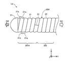
- FIG. 8 is an enlarged plan view of the distal end side of the guide wire 1A according to the second embodiment.
- the first element wire 21 forming the coil body 20A is wound obliquely toward the base end side (first direction DI1) of the coil body 20A.
- the first wire 21 is obliquely wound, so that the surface of each first wire 21 (the surface of the coil body 20A) has a direction opposite to that of the first embodiment, that is, the base end.
- the slope 21 is inclined so as to expand from the side (first direction DI1) toward the distal end (second direction DI2) is opposite to that of the first embodiment, that is, the distal end (second direction DI2).
- a protruding corner 21e is inclined so as to expand from the side (first direction DI1) toward the distal end (second direction DI2) is opposite to that of the first embodiment, that is, the distal end (second direction DI2).
- a protruding corner 21e is inclined so as to expand from the side (first direction DI1) toward the distal end (
- FIG. 9 is a diagram showing an example when the guidewire 1A of the second embodiment is used.
- the configuration of the upper and lower parts of FIG. 9 is the same as that of FIG.
- the slope 21is in the inclined portion 201A is inclined so as to expand from the base end side (first direction DI1) to the distal end side (second direction DI2) of the coil body 20A. Is formed. For this reason, when pushing the guide wire 1A in a state in which the distal end side is not curved into the proximal blood vessel 921 (upper stage in FIG. 9: time t1, indicated by a solid line), each first element wire in the inclined portion 201A is pressed.
- the direction of the slope 21is of the inclined portion 201A and the direction of the corner 21e are opposite to the above directions. Therefore, when the prolapsed guide wire 1A is pushed into the distal blood vessel 922, the frictional resistance applied to the guide wire 1A can be reduced as compared with the configuration without the inclined portion 201A. It is easy to push the guide wire 1A into the distal blood vessel 922. On the other hand, when the prolapsed guidewire 1A is to be pulled out from the distal blood vessel 922, the corner 21e of the inclined portion 201A can increase the frictional resistance applied to the distal end of the guidewire 1A. It becomes easy to release the prolapse of the wire 1A (to make it uncurved).
- the same effect as that of the first embodiment can be obtained by the guide wire 1A of the second embodiment.
- the selectivity blood vessel selectivity
- the inclined portion 201A on the distal end side and disposing the flat portion 202 on the proximal end side, damage to the inner wall 92i such as the blood vessel 92 by the guide wire 1A can be suppressed.
- the cross-sectional shape of the first strand 21 and the second strand 22 forming the coil body 20A substantially elliptical, it is possible to suppress damage to the inner wall 92i such as the blood vessel 92 due to the corner 21e.
- the outer diameter D2 on the distal end side and the outer diameter D21 on the proximal end side of the coil body 20A are substantially the same as in the first embodiment. D2 and D21 may be different.
- the resistance at the time of pushing after reaching the lesion is increased compared to when passing through the healthy part in the blood vessel. Can be improved.
- FIG. 10 is a partial cross-sectional view of the distal end side of a guidewire 1B according to the third embodiment.
- the configuration in the upper and lower sections of FIG. 10 is the same as that in FIG.
- the guide wire 1B of the third embodiment has an inclined portion 201B and a flat portion 202B in which a first wire 21 and a second wire 22 are wound at an angle different from that of the first embodiment in a coil body 20B.
- the first strand 21 in the inclined portion 201B has both the angles ⁇ 31 and ⁇ 32 formed by the long axis 21la and the axis O of the coil body 20B set to the angles ⁇ 11 and ⁇ 12 of the first embodiment. (FIG. 3).
- the angles ⁇ 31 and ⁇ 32 are both acute angles (that is, less than 90 degrees) with respect to the first direction DI1 along the axis O.
- the first direction DI1 is a direction toward the distal end of the coil body 20B.
- the first element wire 21 in the inclined portion 201B has a distance between the base point of the long axis 21la and the axis O of the coil 20B and a distance L32 between the tip of the long axis 21la and the coil body.
- the distance L31 between the axis L and the axis O of 20B is set to be shorter (that is, the same direction as the first embodiment).
- the second strand 22 in the flat portion 202B is rotated by about 90 degrees as compared with the second strand 22 of the first embodiment, and the major axis and the axis of the coil body 20B are rotated.
- the angle formed by O is parallel to the axis O.
- FIG. 11 is a partial cross-sectional view of the distal end side of a guide wire 1C according to the fourth embodiment.
- the configuration of the upper and lower parts of FIG. 11 is the same as that of FIG.
- the guide wire 1C of the fourth embodiment has an inclined portion 201C and a flat portion 202C in which a first wire 21 and a second wire 22 are wound at an angle different from that of the second embodiment in a coil body 20C.
- the first strand 21 of the inclined portion 201C is configured such that both the angles ⁇ 41 and ⁇ 42 formed by the long axis 21la and the axis O of the coil body 20C are the angles ⁇ 21 and ⁇ 22 of the second embodiment. (FIG. 7).
- the angles ⁇ 41 and ⁇ 42 are both acute angles (that is, less than 90 degrees) with respect to the first direction DI1 along the axis O.
- the first direction DI1 is on the base end side of the coil body 20C.
- the first element wire 21 in the inclined portion 201C has an end point on the distal end side of the long axis 21la and a coil body that is longer than the distance L42 between the end point on the base end side of the long axis 21la and the axis O of the coil body 20C.
- the direction is such that the distance L41 between the axis O of 20C and the axis O becomes longer (that is, the same direction as the second embodiment).
- the second strand 22 in the flat portion 202C is rotated by about 90 degrees compared to the second strand 22 of the second embodiment, and the major axis and the axis of the coil body 20C are rotated.
- the angle formed by O is parallel to the axis O.
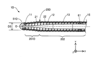
- FIG. 12 is a partial cross-sectional view of the distal end side of a guidewire 1D according to the fifth embodiment.
- the first wire 21 is wound on the inclined portion 201D such that the coil body 20D gradually decreases in diameter from the base end side to the distal end side.
- the distance L12 (the distance between the end point on the base end side of the long axis 21la of the single wire 21 and the axis O of the coil body 20D) described in the first embodiment and the distance L11 ( Both the distance between the end point on the distal end side of the long axis 21la of the first strand 21 and the axis O of the coil body 20) gradually decrease from the proximal end side to the distal end side. That is, the outer diameter D5 on the distal end side of the coil body 20D is smaller than the outer diameter D11 on the proximal end side (FIG. 1), and the distal-side fixing portion 51D is also smaller in diameter than the distal-side fixing portion 51 of the first embodiment. Is formed.
- the guide wire 1D of the fifth embodiment can also provide the same effects as those of the first embodiment.
- the guidewire 1D according to the fifth embodiment has a narrower distal end portion than the guidewire 1 according to the first embodiment, so that the lesion passage property can be further improved.
- FIG. 13 is a partial cross-sectional view of the distal end portion of the guidewire 1E according to the sixth embodiment.
- the first element wire 21 is wound around the inclined portion 201E such that the coil body 20E gradually increases in diameter from the base end side to the distal end side.
- the distance L22 (the distance between the end point on the base end side of the long axis 21la of the first strand 21 and the axis O of the coil body 20A) described in the second embodiment and the distance L21 (The distance between the end point on the distal end side of the long axis 21la of the first strand 21 and the axis O of the coil body 20A) increases gradually from the base end side toward the distal end side. That is, the outer diameter D6 on the distal end side of the coil body 20E is larger than the outer diameter D21 on the proximal end side (FIG. 6), and the distal fixing part 51E is also larger than the distal fixing part 51 of the second embodiment. The diameter is formed.
- the guide wire 1E of the sixth embodiment has a thicker end than the guide wire 1A of the second embodiment, so that damage to the inner wall of a blood vessel or the like due to the guide wire 1E can be further suppressed.
- FIG. 14 is a partial cross-sectional view of the distal end portion of a guidewire 1F according to the seventh embodiment.
- the guide wire 1F according to the seventh embodiment has a coil body 20F in which respective portions are arranged in the order of a flat portion 202, an inclined portion 201, and a flat portion 202 from the distal end side to the proximal end side.
- the inclined portion 201 does not have to be disposed on the tip side of the coil body 20F.
- a flat portion 202 may be arranged on the distal end side of the coil body 20F.
- the flat portion 202 may be disposed on the distal end side of the coil body 20F, and the inclined portion 201 may be disposed on the proximal end side of the coil body 20F (that is, the flat portion 202 on the proximal end side is omitted in FIG. 14). Configuration may be used).
- a plurality of inclined portions 201 and a plurality of flat portions 202 may be provided, and these inclined portions 201 and the flat portions 202 may be alternately arranged along the axis O direction.
- FIG. 15 is a partial cross-sectional view illustrating the entire configuration of a guidewire 1G according to the eighth embodiment.
- the guide wire 1G has the same configuration as the guide wire 1 described in the first embodiment except that the flat portion 202 is omitted. That is, in the guide wire 1G, the coil body 20G includes only the inclined portion 201 and does not have the flat portion 202.
- the same effects as those of the above-described first embodiment can be obtained.
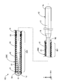
- FIG. 16 is a partial cross-sectional view showing the entire configuration of the guide wire 1H of the ninth embodiment.
- the guide wire 1H further includes an inner coil body 30 in addition to the components described for the guide wire 1A of the second embodiment.
- the inner coil body 30 is formed by spirally winding the element wire 31 around the core shaft 10 (the first reduced diameter portion 12) inside the flat portion 202 of the coil body 20A.
- the wire 31 forming the inner coil body 30 may be a single wire composed of one wire or a stranded wire in which a plurality of wires are twisted.
- the inner coil body 30 When the wire 31 is a single wire, the inner coil body 30 is configured as a single coil, and when the wire 31 is a stranded wire, the inner coil body 30 is configured as a hollow stranded coil.
- the wire 31 can be made of any material, for example, as in the case of the second wire 22.
- the wire 31 and the second wire 22 may be made of the same material or different materials.
- the length of the inner coil body 30 in the direction of the axis O is shorter than that of the flat part 202. Further, the inner coil body 30 is disposed on the tip side of the flat portion 202 in the axis O direction.
- the distal end of the inner coil body 30 is fixed to the core shaft 10 by an inner distal fixing portion 71, and the base end is fixed to the core shaft 10 by an inner proximal fixing portion 72.
- the inner distal fixing portion 71 and the inner proximal fixing portion 72 can be formed of an arbitrary bonding agent, similarly to the distal fixing portion 51. The same bonding agent may be used for the inner distal fixing portion 71, the inner proximal fixing portion 72, and the distal fixing portion 51, or different bonding agents may be used.
- the guide wire 1H of the ninth embodiment includes the inner coil body 30 arranged on the tip side of the flat portion 202. For this reason, when the guide wire 1H is used, when the distal end side of the guide wire 1H is prolapsed (curved), the prolapse progresses beyond the flat portion 202 by being supported by the inner coil body 30. Can be suppressed. As a result, in the guide wire 1H of the ninth embodiment, operability can be further improved.
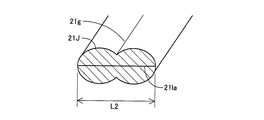
- FIG. 17 is a cross-sectional view of the first strand 21J of the tenth embodiment.
- the inclined portion 201 is formed using the first strand 21J instead of the first strand 21.
- the first strand 21J has a shape in which two strands each having a substantially elliptical cross section are connected, and has a groove 21g.
- a portion having the longest length L2 in the longitudinal direction corresponds to the long axis 21la.
- the first wire 21J can be formed, for example, by passing a wire having a substantially rectangular cross section through a die having a hole having the shape shown in FIG.
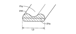
- FIGS. 18 and 19 are cross-sectional views of the first strands 21K and 21L of the tenth embodiment.
- the inclined portion 201 may be formed by using the first strand 21K or the first strand 21L instead of the first strand 21.
- the first strand 21K has a shape in which two strands having a substantially semicircular cross section are connected, and has one groove 21g.
- a portion having the longest length L3 in the longitudinal direction corresponds to the long axis 21la.
- the first strand 21L is formed by connecting three strands having a substantially semicircular cross section and has two grooves 21g.
- a portion having the longest length L4 in the longitudinal direction corresponds to the long axis 21la.
- the groove portion 21g can improve the frictional resistance of the inclined portion 201, and suppresses the peeling of the resin layer when the coil body 20 is coated with the resin layer. it can.
- the configuration of the guide wires 1 and 1A to 1H has been exemplified.
- the configuration of the guidewire can be variously changed.
- the guidewire of each of the above embodiments has been described as a medical device used when inserting a catheter into a blood vessel, but the lymph gland system, biliary system, urinary system, airway system, digestive system, secretory gland and It can also be configured as a guidewire inserted into each organ in the human body such as a reproductive organ.
- the guide wire may not include the third reduced diameter portion 16 and the second large diameter portion 17, and may have a configuration in which the entire core shaft is covered by the coil body.
- the configuration of the core shaft 10 has been exemplified.
- the core shaft includes a first core shaft disposed on the base end side and a second core shaft (also referred to as a ribbon) disposed on the distal end side. May be joined.
- the flat portion of the coil body may be formed using a wire having a substantially circular cross section (a wire having no long axis and no short axis).
- the inclined portion and the flat portion may be formed using the same strand (a strand formed of the same material and having the same shape).
- the inclined portion of the coil body may be configured to be loosely wound with a gap between adjacent first strands.
- the flat portion of the coil body may be configured to be loosely wound with a gap between adjacent second strands.
- the coil body may include, for example, a resin layer coated with a hydrophobic resin material, a hydrophilic resin material, or a mixture thereof.
- the resin layer may be arranged so as to cover only the inclined portion, or may be arranged so as to cover only the flat portion, or in the vicinity of the boundary between the inclined portion and the flat portion (for example, the first strand and the second strand). May be arranged so as to cover the joint portion with the second member.
- the resin layer may be arranged so as to cover the entire coil body (both the inclined portion and the flat portion).
Landscapes
- Health & Medical Sciences (AREA)
- Life Sciences & Earth Sciences (AREA)
- Biophysics (AREA)
- Pulmonology (AREA)
- Engineering & Computer Science (AREA)
- Anesthesiology (AREA)
- Biomedical Technology (AREA)
- Heart & Thoracic Surgery (AREA)
- Hematology (AREA)
- Animal Behavior & Ethology (AREA)
- General Health & Medical Sciences (AREA)
- Public Health (AREA)
- Veterinary Medicine (AREA)
- Media Introduction/Drainage Providing Device (AREA)
Abstract
Priority Applications (5)
| Application Number | Priority Date | Filing Date | Title |
|---|---|---|---|
| EP18924624.2A EP3815733B1 (fr) | 2018-06-29 | 2018-06-29 | Fil-guide |
| PCT/JP2018/024871 WO2020003505A1 (fr) | 2018-06-29 | 2018-06-29 | Fil-guide |
| JP2020526861A JP7216726B2 (ja) | 2018-06-29 | 2018-06-29 | ガイドワイヤ |
| CN201880094711.6A CN112334180B (zh) | 2018-06-29 | 2018-06-29 | 导丝 |
| US17/119,402 US12083297B2 (en) | 2018-06-29 | 2020-12-11 | Guide wire |
Applications Claiming Priority (1)
| Application Number | Priority Date | Filing Date | Title |
|---|---|---|---|
| PCT/JP2018/024871 WO2020003505A1 (fr) | 2018-06-29 | 2018-06-29 | Fil-guide |
Related Child Applications (1)
| Application Number | Title | Priority Date | Filing Date |
|---|---|---|---|
| US17/119,402 Continuation US12083297B2 (en) | 2018-06-29 | 2020-12-11 | Guide wire |
Publications (1)
| Publication Number | Publication Date |
|---|---|
| WO2020003505A1 true WO2020003505A1 (fr) | 2020-01-02 |
Family
ID=68986334
Family Applications (1)
| Application Number | Title | Priority Date | Filing Date |
|---|---|---|---|
| PCT/JP2018/024871 Ceased WO2020003505A1 (fr) | 2018-06-29 | 2018-06-29 | Fil-guide |
Country Status (5)
| Country | Link |
|---|---|
| US (1) | US12083297B2 (fr) |
| EP (1) | EP3815733B1 (fr) |
| JP (1) | JP7216726B2 (fr) |
| CN (1) | CN112334180B (fr) |
| WO (1) | WO2020003505A1 (fr) |
Cited By (1)
| Publication number | Priority date | Publication date | Assignee | Title |
|---|---|---|---|---|
| JP7051032B1 (ja) * | 2021-11-01 | 2022-04-08 | 朝日インテック株式会社 | ガイドワイヤ |
Citations (6)
| Publication number | Priority date | Publication date | Assignee | Title |
|---|---|---|---|---|
| JP2002505167A (ja) | 1998-03-04 | 2002-02-19 | シー・アール・バード・インコーポレーテッド | 形成可能な先端を有する柔軟で耐キンク性の低摩擦ガイドワイヤ及びその製造方法 |
| JP2002210019A (ja) | 2001-01-16 | 2002-07-30 | Olympus Optical Co Ltd | 医療器具用のコイル、その製造方法及び製造装置 |
| JP2013126512A (ja) * | 2011-12-19 | 2013-06-27 | Sumitomo Bakelite Co Ltd | 医療機器、および医療機器の製造方法 |
| JP2015013005A (ja) * | 2013-07-05 | 2015-01-22 | 朝日インテック株式会社 | コイル体、およびコイル体を備えるガイドワイヤ、カテーテル、および医療用処置具 |
| JP2017196368A (ja) * | 2016-04-28 | 2017-11-02 | 株式会社エフエムディ | 医療用ガイドワイヤ |
| JP2018108119A (ja) * | 2016-12-28 | 2018-07-12 | テルモ株式会社 | ガイドワイヤおよび医療用コイル |
Family Cites Families (15)
| Publication number | Priority date | Publication date | Assignee | Title |
|---|---|---|---|---|
| US3452740A (en) * | 1966-05-31 | 1969-07-01 | Us Catheter & Instr Corp | Spring guide manipulator |
| US4430083A (en) * | 1981-03-06 | 1984-02-07 | American Hospital Supply Corporation | Infusion catheter |
| US5658264A (en) * | 1994-11-10 | 1997-08-19 | Target Therapeutics, Inc. | High performance spiral-wound catheter |
| DK1040843T3 (da) * | 1999-03-29 | 2006-01-30 | William Cook Europe As | En guidewire |
| JP4181081B2 (ja) | 2004-04-23 | 2008-11-12 | 朝日インテック株式会社 | 医療用ガイドワイヤ |
| US8043232B2 (en) * | 2005-08-05 | 2011-10-25 | Cook Medical Technologies Llc | High performance wire guide |
| JP4896245B2 (ja) | 2010-03-31 | 2012-03-14 | 朝日インテック株式会社 | ガイドワイヤ |
| US20110245775A1 (en) * | 2010-04-01 | 2011-10-06 | Cook Incorporated | Tapered sheath |
| US8500657B2 (en) * | 2010-08-23 | 2013-08-06 | Abbott Cardiovascular Systems, Inc. | Twisted ribbon wire guidewire coil |
| JP5762789B2 (ja) * | 2011-03-30 | 2015-08-12 | テルモ株式会社 | ガイドワイヤ |
| EP2612608B1 (fr) * | 2011-09-12 | 2014-12-17 | Olympus Medical Systems Corp. | Bobine médicale, son procédé de fabrication et appareil médical |
| JP2013192914A (ja) | 2012-03-23 | 2013-09-30 | Asahi Intecc Co Ltd | ガイドワイヤ |
| WO2014203336A1 (fr) * | 2013-06-18 | 2014-12-24 | 住友ベークライト株式会社 | Dispositif médical et son procédé de fabrication |
| WO2017176890A1 (fr) * | 2016-04-06 | 2017-10-12 | Boston Scientific Scimed, Inc. | Fil-guide |
| JP6171239B1 (ja) * | 2016-08-02 | 2017-08-02 | 株式会社エフエムディ | 医療用ガイドワイヤ及び医療用ガイドワイヤの製造方法 |
-
2018
- 2018-06-29 WO PCT/JP2018/024871 patent/WO2020003505A1/fr not_active Ceased
- 2018-06-29 EP EP18924624.2A patent/EP3815733B1/fr active Active
- 2018-06-29 JP JP2020526861A patent/JP7216726B2/ja active Active
- 2018-06-29 CN CN201880094711.6A patent/CN112334180B/zh active Active
-
2020
- 2020-12-11 US US17/119,402 patent/US12083297B2/en active Active
Patent Citations (6)
| Publication number | Priority date | Publication date | Assignee | Title |
|---|---|---|---|---|
| JP2002505167A (ja) | 1998-03-04 | 2002-02-19 | シー・アール・バード・インコーポレーテッド | 形成可能な先端を有する柔軟で耐キンク性の低摩擦ガイドワイヤ及びその製造方法 |
| JP2002210019A (ja) | 2001-01-16 | 2002-07-30 | Olympus Optical Co Ltd | 医療器具用のコイル、その製造方法及び製造装置 |
| JP2013126512A (ja) * | 2011-12-19 | 2013-06-27 | Sumitomo Bakelite Co Ltd | 医療機器、および医療機器の製造方法 |
| JP2015013005A (ja) * | 2013-07-05 | 2015-01-22 | 朝日インテック株式会社 | コイル体、およびコイル体を備えるガイドワイヤ、カテーテル、および医療用処置具 |
| JP2017196368A (ja) * | 2016-04-28 | 2017-11-02 | 株式会社エフエムディ | 医療用ガイドワイヤ |
| JP2018108119A (ja) * | 2016-12-28 | 2018-07-12 | テルモ株式会社 | ガイドワイヤおよび医療用コイル |
Non-Patent Citations (1)
| Title |
|---|
| See also references of EP3815733A4 |
Cited By (2)
| Publication number | Priority date | Publication date | Assignee | Title |
|---|---|---|---|---|
| JP7051032B1 (ja) * | 2021-11-01 | 2022-04-08 | 朝日インテック株式会社 | ガイドワイヤ |
| WO2023073985A1 (fr) * | 2021-11-01 | 2023-05-04 | 朝日インテック株式会社 | Fil-guide |
Also Published As
| Publication number | Publication date |
|---|---|
| JP7216726B2 (ja) | 2023-02-01 |
| CN112334180A (zh) | 2021-02-05 |
| EP3815733A4 (fr) | 2022-03-16 |
| US12083297B2 (en) | 2024-09-10 |
| CN112334180B (zh) | 2022-12-13 |
| EP3815733A1 (fr) | 2021-05-05 |
| US20210093839A1 (en) | 2021-04-01 |
| JPWO2020003505A1 (ja) | 2021-06-17 |
| EP3815733B1 (fr) | 2025-08-06 |
Similar Documents
| Publication | Publication Date | Title |
|---|---|---|
| US5551444A (en) | Flexible guidewire with radiopaque outer coil and non-radiopaque inner coil | |
| JP4028245B2 (ja) | ガイドワイヤ | |
| EP2392376A1 (fr) | Fil de guidage | |
| EP2481441A1 (fr) | Fil-guide | |
| JPH08173547A (ja) | 医療用ガイドワイヤ | |
| US20230321409A1 (en) | Guide wire | |
| US20150119757A1 (en) | Coil body and guide wire | |
| CN112312954B (zh) | 导丝 | |
| WO2020016986A1 (fr) | Fil-guide et procédé de fabrication de fil-guide | |
| WO2020003505A1 (fr) | Fil-guide | |
| JP2020022648A (ja) | ガイドワイヤ | |
| US20220184349A1 (en) | Guide Wires | |
| US12589227B2 (en) | Guide wires | |
| CN115175723B (zh) | 导丝 | |
| US20220118231A1 (en) | Guide wire | |
| JP7546454B2 (ja) | ガイドワイヤ | |
| JP2018108119A (ja) | ガイドワイヤおよび医療用コイル | |
| CN115955987B (zh) | 导丝 | |
| US9014816B2 (en) | Medical lead with filler layer | |
| US11931535B2 (en) | Guide wire | |
| CN112312955B (zh) | 导丝 | |
| CN211835745U (zh) | 导丝 | |
| JP7256582B2 (ja) | ガイドワイヤ | |
| JP2022166396A (ja) | ガイドワイヤ | |
| JP2026001913A (ja) | ワイヤおよびガイドワイヤ |
Legal Events
| Date | Code | Title | Description |
|---|---|---|---|
| 121 | Ep: the epo has been informed by wipo that ep was designated in this application |
Ref document number: 18924624 Country of ref document: EP Kind code of ref document: A1 |
|
| ENP | Entry into the national phase |
Ref document number: 2020526861 Country of ref document: JP Kind code of ref document: A |
|
| NENP | Non-entry into the national phase |
Ref country code: DE |
|
| WWE | Wipo information: entry into national phase |
Ref document number: 2018924624 Country of ref document: EP |
|
| WWG | Wipo information: grant in national office |
Ref document number: 2018924624 Country of ref document: EP |