WO2020003516A1 - Dispositif de décollement et procédé de décollement - Google Patents
Dispositif de décollement et procédé de décollement Download PDFInfo
- Publication number
- WO2020003516A1 WO2020003516A1 PCT/JP2018/024901 JP2018024901W WO2020003516A1 WO 2020003516 A1 WO2020003516 A1 WO 2020003516A1 JP 2018024901 W JP2018024901 W JP 2018024901W WO 2020003516 A1 WO2020003516 A1 WO 2020003516A1
- Authority
- WO
- WIPO (PCT)
- Prior art keywords
- peeling
- adhesive tape
- pressing roller
- substrate
- metal mask
- Prior art date
- Legal status (The legal status is an assumption and is not a legal conclusion. Google has not performed a legal analysis and makes no representation as to the accuracy of the status listed.)
- Ceased
Links
Images




Classifications
-
- B—PERFORMING OPERATIONS; TRANSPORTING
- B65—CONVEYING; PACKING; STORING; HANDLING THIN OR FILAMENTARY MATERIAL
- B65H—HANDLING THIN OR FILAMENTARY MATERIAL, e.g. SHEETS, WEBS, CABLES
- B65H41/00—Machines for separating superposed webs
-
- H—ELECTRICITY
- H10—SEMICONDUCTOR DEVICES; ELECTRIC SOLID-STATE DEVICES NOT OTHERWISE PROVIDED FOR
- H10P—GENERIC PROCESSES OR APPARATUS FOR THE MANUFACTURE OR TREATMENT OF DEVICES COVERED BY CLASS H10
- H10P72/00—Handling or holding of wafers, substrates or devices during manufacture or treatment thereof
- H10P72/70—Handling or holding of wafers, substrates or devices during manufacture or treatment thereof for supporting or gripping
Definitions
- the present invention relates to a peeling device and a peeling method.
- a cover film In circuit boards (including flexible circuit boards), semiconductor wafers and display devices, a cover film, a so-called protective film, is attached in the manufacturing process to protect the functional surface, the cover film is peeled off, and the process proceeds to the next step It is generally done.
- an apparatus and a peeling method for pressing the adhesive surface of the adhesive tape against the cover film and peeling off the cover film by the adhesive force of the adhesive tape have been conventionally used.
- peeling a cover film of almost the same size as a circuit board or semiconductor wafer it is easy to peel off the cover film by simply pressing the adhesive tape against the cover film and pulling up or winding up the adhesive tape. It is possible.
- a peeling device and a peeling method it was difficult to peel off only a specific range of the cover film.
- Patent Document 1 discloses a peeling device that peels only a specific portion of a cover film attached to a circuit board or the like.
- the peeling device described in Patent Literature 1 cuts a half of the periphery of a part to be peeled by half-cutting, presses an adhesive surface of an adhesive tape on the inside surrounded by the cut with a pressing member, and then adheres the pressing member to the inside. That is, the cover film is separated from the circuit board together with the tape and the cover film of the portion to be separated is separated.
- the peeling device described in Patent Literature 1 makes a cut by half-cutting around the part to be peeled of the cover film, presses the adhesive tape to the part to be peeled of the cover film surrounded by the cut, and applies the adhesive force of the adhesive tape.
- This is an apparatus for peeling the cover film from the lower substrate. Therefore, when a functional pattern such as a conductive pattern or an electrode is formed over a part to be peeled off from a lower circuit board and a part not to be peeled, it is not possible to make a cut in the cover film on the functional pattern. It is difficult because it may damage the product.
- the peeling device described in Patent Literature 1 has a problem that it is not possible to peel off only a specific peeling target portion having no cut.
- the peeling device described in Patent Document 1 presses the pressure-sensitive adhesive tape uniformly with respect to an area of 80% or more and 100% or less of the surface area of the half-cut portion to be peeled, and presses the pressing member with a circuit. This is to separate the cover film away from the substrate. Therefore, when the circuit board is a laminated substrate (flexible laminated substrate) and the uppermost layer substrate is peeled off from the lower layer substrate, the area of the portion to be peeled becomes large, or the portion to be peeled has a large aspect ratio. If there is, there is a problem that a simple lifting operation of the pressing member cannot be performed or the circuit board is warped at the time of the separation.
- the peeling device described in Patent Literature 1 has a configuration in which the peeling head (working head) moves linearly in one direction. Therefore, it is possible to cope with a case where a plurality of portions to be peeled are scattered on the uppermost substrate. Can not.
- the direction and shape of the pressing plane of the pressing member must be switched in accordance with the part to be peeled, and there is a problem that productivity is significantly deteriorated.
- An object of the present invention is to provide a peeling device and a peeling method capable of peeling from a substrate and cutting and separating a portion to be peeled from an uppermost layer substrate.
- a peeling device of the present invention is a peeling device for peeling a portion to be peeled off of an uppermost substrate of a laminated substrate from an lower substrate by the adhesive force of an adhesive tape, wherein the peeling device is disposed on an upper surface side of the uppermost substrate.
- a metal mask fixing frame that holds and fixes a metal mask having an opening that defines the range of the target portion, and a pressing roller that presses the adhesive layer of the adhesive tape against the uppermost substrate in the opening from the upper surface of the metal mask.
- a peeling head having an adhesive tape take-up roll for winding the adhesive tape and an adhesive tape sending roll for sending out the adhesive tape, and it is possible to switch a moving direction of the peeling head, and the adhesive layer on the uppermost substrate.
- a peeling head driving mechanism for moving the pressing roller in a pressed state.
- the pressing roller moves in a state where the adhesive layer of the adhesive tape is adhered to the uppermost substrate, so that the edge portion on the lower surface side of the opening portion of the metal mask. Peeling can be performed while cutting the part to be peeled. Further, since the peeling head can switch the moving direction, the peeling target portion is peeled from the lower layer substrate regardless of the size, shape and arrangement of the peeling target portion, and the peeling target portion is peeled from the uppermost substrate. Can be cut and separated.
- the pressure-sensitive adhesive tape take-up roll and the pressure-sensitive adhesive tape delivery roll are linearly arranged in a plan view with the pressure roller interposed therebetween.
- a ⁇ -axis drive mechanism that rotates the adhesive tape take-up roll and the adhesive tape delivery roll along an upper surface of the metal mask, and a pressing roller that moves the pressing roller vertically with respect to the upper surface of the metal mask.
- a lifting mechanism that uses the lifting mechanism to raise the adhesive tape take-up roll and the adhesive tape delivery roll along an upper surface of the metal mask to the upper surface of the metal mask.
- the peeling head can move the pressing roller, the adhesive tape take-up roll, and the adhesive tape unwinding roll in accordance with the opening of the metal mask, that is, the arrangement of the part to be peeled. Regardless, the uppermost substrate can be separated from the lower substrate. Also, if the pressing roller is raised, the adhesive tape follows the pressing roller and rises upward from the metal mask, and the part to be peeled is cut from the uppermost substrate at the edge of the opening, and cut and separated reliably. It becomes possible.
- the pressing roller has flexibility, and an axial length thereof is larger than a maximum width of the opening in a direction orthogonal to a moving direction of the pressing roller. It is preferable that the length of the adhesive tape is long and does not span the openings arranged outside the movement locus of the pressing roller.
- the pressure roller has flexibility, and peels while pressing around the edge of the opening to be peeled by the pressure roller, so that the metal mask does not rise and cutting and peeling of the part to be peeled can be performed. It becomes. Further, if the length is within the range of the length of the pressing roller, the separation target portion can be separated regardless of the shape and size of the separation target portion. Since the adhesive tape does not span the opening outside the movement locus of the pressing roller, it is possible to peel off only the uppermost substrate within the range of the movement locus.
- the pressing roller peels the peeling target portion by the adhesive force of the adhesive tape while moving the pressing tape by pressing the adhesive tape against the peeling target portion. It is preferable that the pressure-sensitive adhesive tape is controlled so as to be lifted in a direction away from the laminated substrate at an end of the pressing roller in the moving direction at an edge of the pressing roller.
- the portion to be peeled can be more reliably cut and separated from the uppermost substrate.
- the pressure-sensitive adhesive tape take-up roll winds the pressure-sensitive adhesive tape in synchronization with a peeling operation in which the pressing roller presses the pressure-sensitive adhesive tape against the peeling target portion and moves. Is preferably controlled.
- the separated portion to be peeled (hereinafter referred to as the uppermost layer substrate piece) can be peeled again. Since it can be separated from the target portion, it is possible to prevent the uppermost layer substrate piece from hindering the next peeling operation.
- the peeling head is disposed immediately adjacent to the pressure-sensitive adhesive tape sending roll side of the pressing roller, and a stopper mechanism for applying a brake to the pressure-sensitive adhesive tape during the ascent operation of the pressing roller. It is preferable to have
- the adhesive tape is rolled and the stopper mechanism applies tension to the adhesive tape to prevent the adhesive tape from loosening, and the adhesive tape follows the pressing roller when the pressing roller rises.
- the separation target portion can be reliably separated from the uppermost substrate.
- the peeling head includes a mask pressing mechanism that is disposed immediately adjacent to the pressure roller on the side of the pressure-sensitive adhesive tape take-up roll, and that presses the metal mask during a rising operation of the pressing roller. It is preferable to have.
- the metal mask is pressed by the mask holding mechanism and the pressing roller is raised in this way, it is possible to prevent the metal mask from floating due to the adhesive force of the adhesive tape, and a gap is formed between the metal mask and the uppermost substrate. Since it cannot be performed, it is possible to more reliably cut and separate the portion to be peeled from the uppermost substrate.
- the metal mask fixing frame has an alignment mechanism for correcting a position between the opening and the portion to be stripped.
- a peeling method of the present invention is a peeling method of peeling a portion to be peeled of the uppermost substrate from the lower substrate by the adhesive force of the adhesive tape using the peeling device described above, Transporting the substrate to a predetermined position and elevating the substrate to a position where the substrate comes into contact with the metal mask; correcting the position of the opening portion of the metal mask and the portion to be peeled; and the pressing position and moving direction of the pressing roller Adjusting the pressure-sensitive adhesive tape to the arrangement of the portions to be peeled, pressing the pressure roller down, and further pressing the pressure-sensitive adhesive tape against the uppermost substrate in the opening by moving the pressure roller to the opening, and the pressure-sensitive adhesive tape.
- the peeling method of the present invention by moving the pressing roller in a state where the adhesive layer of the adhesive tape is pressed against the uppermost substrate in the opening of the metal mask, the portion to be peeled at the edge on the lower surface side of the opening Can be peeled off while being cut. Then, when the pressing roller reaches the end of the opening of the metal mask in the direction of movement of the pressing roller, the pressing roller is raised to cut the part to be peeled off at the edge of the opening, and separate the part to be peeled from the uppermost substrate. It becomes possible.
- the laminated substrate has a plurality of the stripping target portions in a stripping target range, and the metal mask has openings corresponding to the shape and arrangement of the stripping target portions.
- the pressing position and the moving direction of the pressing roller are switched in accordance with the arrangement of the openings.
- FIG. 1 is a perspective view illustrating a schematic configuration of a peeling device 1 according to an embodiment.
- FIG. 2 is a side view of the peeling device 1 viewed from a front side in a Y direction in FIG. 1.
- FIG. 2 is an enlarged perspective view showing a peeling head 6 shown in FIG. 1.
- FIG. 3 is an explanatory diagram illustrating a configuration and an operation of a peeling head 6.
- FIG. 3 is a view showing a flexible laminated substrate 2 which is an example of a laminated substrate as a work to be peeled.
- FIG. 3 is a process flow chart showing main steps of a peeling method according to the embodiment.
- FIG. 4 is an explanatory diagram illustrating main steps of a peeling method according to the embodiment.
- a peeling device 1 and a peeling method according to an embodiment of the present invention will be described with reference to FIGS.
- a flexible laminated substrate 2 will be described as an example of a laminated substrate that is a work.
- FIG. 1 is a perspective view showing a schematic configuration of the peeling device 1 according to the embodiment
- FIG. 2 is a front view of the peeling device 1 as viewed from the near side in the Y direction of FIG.
- FIG. 1 omits illustration of the flexible laminated substrate 2.
- the transport direction of the flexible laminated substrate 2 is the X direction (or X axis)
- the direction orthogonal to the X direction is the Y direction (or Y axis)
- the direction perpendicular to the XY plane is the Z direction. Or, it is described as a vertical direction.
- the peeling device 1 includes a peeling head 6 on an upper portion of a base pedestal 5, a substrate winding roll unit 7 that is disposed at both ends in the X direction and transports the flexible laminated substrate 2, and And a substrate delivery roll unit 8.
- a table 9 (see FIG. 2) for mounting and holding the flexible laminated substrate 2 and a metal mask 10 disposed above the table 9 are provided between the substrate winding unit 7 and the substrate delivery roll unit 8. And are arranged.
- the table 9 is raised by a table elevating mechanism (not shown) to a position where the flexible laminated substrate 2 comes into contact with the metal mask 10 during the peeling operation.
- the metal mask 10 is fixed to a metal mask fixing frame 11 by a plurality of mask fixing tools 12.
- a plurality of openings 13 are provided in the metal mask 10.
- the opening 13 shown in FIG. 1 is different from the actual one in arrangement and shape, and indicates the existence.
- the metal mask 10 can be moved in the X direction and the Y direction by the X-axis drive mechanism 14 and the Y-axis drive mechanism 15, and a portion 46 (see FIG. 5) to be peeled of the flexible laminated substrate 2 and an opening 13 with respect to the position in the plane direction.
- the position correction includes correction of an angle (posture) with respect to the X axis or the Y axis.
- the position correction is performed by image processing based on the detection results of the pair of detection cameras 16 arranged on both sides of the peeling head 6 in the Y direction.
- the detection camera 16 is an imaging device such as a CCD camera.
- the alignment mechanism 18 includes the X-axis drive mechanism 14, the Y-axis drive mechanism 15, and the detection camera 16.
- the peeling device 1 has a peeling head driving mechanism 19.
- the peeling head driving mechanism 19 has a head X-axis driving mechanism 21 that moves the peeling head 6 in the X direction, and a head Y-axis driving mechanism 22 that moves the peeling head 6 in the Y direction.
- Both the head X-axis drive mechanism 21 and the head Y-axis drive mechanism 22 operate by a well-known ball screw mechanism.
- a well-known ball screw mechanism can be used, and a description thereof will be omitted.
- the substrate winding roll unit 7 includes a substrate winding roll 28, a winding dancer roller 27, and an exit roller 26.
- the substrate delivery roll unit 8 has a substrate delivery roll 23, a delivery dancer roller 24, and an entrance roller 25.
- the flexible laminated substrate 2 is stretched between a substrate delivery roll unit 8 and a substrate take-up roll unit 7.
- the substrate take-up roll 28 is a drive roll
- the substrate delivery roll 23 is a driven roll.
- the flexible laminated substrate 2 is delivered from a substrate delivery roll 23, passed through a gap between the table 9 and the metal mask 10 via a dancer roller 24 and an entrance roller 25, to an exit roller 26, and is taken up by a winding dancer.
- the substrate is taken up by a substrate take-up roll 28 via a roller 27.
- the flexible laminated substrate 2 is stretched without slack between the substrate sending roll 23 and the substrate winding roll 28.
- the flexible laminated substrate 2 is vacuum-adsorbed to the table 9 during the peeling operation.
- the transport direction of the flexible laminated substrate 2 is indicated by an arrow.
- a power supply device and a control unit for controlling the entire driving of the peeling device 1 are stored inside the base frame 5.
- FIG. 3 is a perspective view showing the peeling head 6 in an enlarged manner.
- the peeling head 6 includes an adhesive tape winding roll 30 for winding the adhesive tape 20, an adhesive tape sending roll 31 for sending the adhesive tape 20, and a gap between the adhesive tape winding roll 30 and the adhesive tape sending roll 31.
- a pressing roller 32 is provided to press the adhesive tape 20 against the flexible laminated substrate 2 (see FIGS. 2 and 7).
- the adhesive tape take-up roll 30, the adhesive tape delivery roll 31, and the pressing roller 32 are attached to a head body 38 (see FIG. 4).
- the peeling head 6 shown in FIG. 3 shows a state before the peeling device 1 is started.
- the adhesive tape take-up roll 30, the pressing roller 32, and the adhesive tape delivery roll 31 are arranged linearly in a plan view.
- the adhesive tape take-up roll 30 is a driving roll
- the adhesive tape delivery roll 31 is a driven roll.
- the peeling head 6 further includes a ⁇ -axis drive mechanism 33 that rotates along the upper surface 10a of the metal mask 10 without changing the arrangement of the adhesive tape take-up roll 30, the pressing roller 32, and the adhesive tape delivery roll 31. .
- the ⁇ -axis drive mechanism 33 adjusts the angle (posture) in the plane direction with respect to the arrangement of the openings 13 of the pressing roller 32.
- the peeling head 6 can be moved up and down with respect to the metal mask 10 by a vertically moving drive mechanism 34.
- the surface that contacts the pressing roller 32 is referred to as a non-adhesive layer 20a, and the opposite surface is referred to as an adhesive layer 20b.
- the peeling head 6 includes a pressing roller elevating mechanism 35 for elevating and lowering the pressing roller 32 with respect to the upper surface of the metal mask 10, a mask pressing mechanism 36 for preventing the metal mask 10 from floating, and an excessive unwinding of the adhesive tape 20. And a stopper mechanism 37 for suppressing the loosening due to.
- the detailed configurations and operations of the pressing roller 32, the pressing roller lifting mechanism 35, the mask pressing mechanism 36, and the stopper mechanism 37 will be described later with reference to FIG.
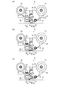
- FIG. 4 is an explanatory diagram illustrating the configuration and operation of the peeling head 6.
- the configuration and operation of the peeling head 6 will be described, and details of the peeling operation will be described later with reference to FIGS. 4A illustrates a state during the peeling operation
- FIG. 4B illustrates a state immediately before the peeling operation is completed and the pressing roller 32 is raised
- FIG. 4C illustrates a state where the peeling operation is completed and the pressing roller 32 is raised. Immediately after it is shown.
- the pressing roller 32 presses the metal mask 10 during the peeling operation.
- the adhesive tape 20 is stretched from the adhesive tape delivery roll 31 to the intermediate roller 39, the stopper roller 40, and the pressing roller 32 in this order, and is wound around the adhesive tape winding roll 30 without slack.
- the mask holding mechanism 36 has a mask holding roller 41 and a mask holding roller driving unit 42 that moves the mask holding roller 41 up and down with respect to the metal mask 10.
- the mask pressing roller 41 is disposed immediately adjacent to the pressure roller-32 on the side of the adhesive tape winding roll 30. It is preferable that the length of the mask pressing roller 41 in the axial direction is equal to or longer than the length of the pressing roller 32, and the mask pressing roller 41 does not necessarily have to have flexibility.
- the mask pressing roller 41 projects from the lower end of the mask pressing roller driving unit 42. During the peeling operation, the mask pressing roller 41 is on standby at a position where it does not contact the metal mask 10.
- the intermediate roller 39 has a function of reducing the slack of the adhesive tape between the adhesive tape delivery roll 31 and the pressing roller 32 and applying an appropriate brake that does not affect winding.
- the pressing roller 32, the stopper roller 40, and the stopper mechanism 37 are attached to the pressing roller elevating mechanism 35, and are configured to lower or ascend with respect to the metal mask 10 by the pressing roller elevating mechanism 35.
- the stopper mechanism 37 has a stopper roller 40 and a stopper portion 43.
- the stopper 43 can be moved up and down independently of the pressing roller elevating mechanism 35.
- the stopper roller 40 and the stopper portion 43 are separated from each other, and the adhesive tape 20 can be wound by the adhesive tape winding roll 30.
- the moving direction of the peeling head 6 is indicated by a thick arrow
- the moving direction of the adhesive tape 20 is indicated by a thin arrow.
- the pressing roller 32 presses the adhesive tape 20 against the metal mask 10 and uses the flexibility of the pressing roller 6 to adhere the adhesive tape 20 to the uppermost substrate 48 in the opening 13 provided in the metal mask 10. Press the layer 20b (see FIG. 7).
- the pressing roller 6 rolls while moving in the direction of the thick arrow, and peels off the uppermost substrate 48 in the opening 13 from the lower substrate 47.
- the peeling head 6 moves in the direction of the arrow shown in the peeling target range 49 in FIG.
- FIG. 4B shows a state immediately before the peeling operation is completed and the pressing roller 32 is raised.
- the structure of each mechanism and each roller has been described with reference to FIG.
- the horizontal movement of the peeling head 6 is stopped, the stopper portion 43 descends toward the stopper roller 40, and the adhesive tape 20 is pressed against the stopper roller 40 to apply a brake to the adhesive tape 20.
- the adhesive tape 20 is not loosened due to the tension between the adhesive tape take-up roll 30 and the stopper roller 40.
- the mask pressing roller 41 descends until the mask pressing roller driving unit 42 presses the metal mask 10.
- FIG. 4C shows a state immediately after the peeling operation is completed and the pressing roller 32 is raised.
- the structure of each mechanism and each roller has been described with reference to FIG.
- the pressing roller 6 is raised until it is separated from the metal mask.
- the mask pressing roller 41 presses the metal mask 10.
- the pressing of the metal mask 10 by the mask pressing roller 41 continues until the pressing roller 6 stops rising.
- the stopper mechanism 37 applies a brake to the adhesive tape 20 until the next peeling operation is started, and suppresses the looseness of the adhesive tape 20.
- illustration is omitted, when the pressing roller 32 is raised, the mask pressing roller 41 is raised to the position shown in FIG. Note that there is no vertical movement of the peeling head 6 in each step shown in FIGS. 4 (a) to 4 (c). The details of the peeling operation and the peeling method by the peeling head 6 described above will be described with reference to FIGS.
- FIG. 5 is a view showing a flexible laminated substrate 2 which is an example of a laminated substrate as a workpiece to be peeled.
- FIG. 5A is a plan view showing a part of the flexible laminated substrate 2, showing an example of the arrangement of the portions 46 (46 a, 46 b, 46 c) of the uppermost substrate 48 and the openings 13 of the metal mask 10. Represents.
- the part to be peeled is a range where the uppermost substrate 48 is to be peeled, and is defined by the openings 13 (13a, 13b, 13c) of the metal mask 10.
- FIG. 5A are for explaining the peeling operation and schematically show an example different from the actual one, and the separation target portions 46 are arranged more densely. In some cases, they may be arranged sparsely.
- FIG. 5B is a cross-sectional view illustrating an example of the configuration of the flexible laminated substrate 2. In FIG. 5B, the thickness is exaggerated.
- the parts 46a, 46b and 46c to be peeled are collectively referred to as a part 46 to be peeled, and the openings 13a, 13b and 13c are collectively referred to as an opening 13.
- the flexible laminated substrate 2 is composed of a plurality of layers of substrates.
- the flexible laminated substrate 2 includes a lower substrate 47 and an uppermost substrate 48 bonded to the lower substrate 47 with a thermosetting resin or the like.
- the case where the lower substrate 47 is a multilayer substrate having two or more layers is also included.
- a functional pattern such as a conductive pattern or an electrode is formed on the upper surface, the lower surface, or both upper and lower surfaces of each of the uppermost substrate 48 and the lower substrate 47, they are not shown.
- the uppermost substrate 48 may not have a functional pattern.
- the thickness of the uppermost substrate 4 is, for example, 10 ⁇ m to 80 ⁇ m, and the total thickness of the flexible laminated substrate 2 is not particularly limited as long as it can be wound around the substrate take-up roll 28 and the substrate delivery roll 23.
- the laminated substrate is not limited to the tape-shaped flexible laminated substrate 2 but can be adapted to a single-layer laminated substrate.
- the metal mask 10 and the opening 13 of the metal mask 10 are represented by two-dot chain lines.
- a group A in which four separation target portions 46 a (openings 13 a) having the same shape and the same size are arranged in parallel to the feeding direction (thick arrow) of the flexible laminated substrate 2.
- Group B in which three portions 46b (openings 13b) having substantially the same shape and the same size are arranged orthogonally to the array of the group A, and the portion 46c to be peeled having the same shape and the same size as the array of the group A
- Group C arranged two obliquely.
- the thin arrows in the peeling target range 49 in FIG. 5A indicate the peeling order.
- the thickness of the metal mask 10 is about 30 ⁇ m to 80 ⁇ m, but is not limited.
- a region where the pressing roller 32 moves while pressing the metal mask 10 is referred to as a movement locus.
- the axial length of the pressing roller 32 is longer than the maximum width of the openings 13a, 13b, 13c in a direction orthogonal to the moving direction of the pressing roller 32. Therefore, if the size of the opening 13 in the group A, the group B, and the group C is within the length of the pressing roller 32, there is no need to replace the pressing roller 32.
- the adhesive tape 20 has a width that does not span the openings 13 arranged outside the movement locus of the pressing roller 32. That is, the adhesive tape 20 does not span the opening 13b of the group B when peeling the group A, and the adhesive tape 20 does not span the opening 13c of the group C when peeling the group B.
- the peeling device 1 described above is a peeling device that peels off the part 46 to be peeled of the uppermost substrate 48 of the flexible laminated substrate 2 as the laminated substrate from the lower substrate 47 by the adhesive force of the adhesive tape 20.
- the peeling apparatus 1 includes a metal mask fixing frame 11 for holding and fixing a metal mask 10 having an opening 13 defining a range of a part 46 to be peeled of an uppermost substrate 48, and an adhesive tape 20 from an upper surface 10 a of the metal mask 10.
- a pressure roller 32 for pressing the layer 20 b against the uppermost substrate 48 in the opening 13, an adhesive tape winding roll 30 for winding the adhesive tape 20, and a peeling head 6 having an adhesive tape sending roll 31 for sending the adhesive tape 20. have.
- the peeling device 1 has a peeling head driving mechanism 19 that can switch the moving direction of the peeling head 6 and moves the pressing roller 32 while pressing the adhesive layer 20b against the uppermost substrate 48.
- the pressure roller 32 is attached to the uppermost substrate 48 with the adhesive layer 20b of the adhesive tape 20 adhered to the opening 13 (13a, 13b, 13c) of the metal mask 10. Is moved, it is possible to peel off while cutting the portions 46 (46a, 46b, 46c) to be peeled at the edge 50 (see FIG. 7B) on the lower surface side of the opening 13. Further, since the moving direction of the peeling head 32 can be switched, the peeling target portion 46 can be peeled from the lower substrate 47 regardless of the size, shape and arrangement of the peeling target portion 46.
- the adhesive tape take-up roll 30 and the adhesive tape delivery roll 31 are linearly arranged in a plan view with the pressing roller 32 interposed therebetween.
- the peeling head 6 includes a ⁇ -axis driving mechanism 33 that rotates the pressing roller 32, the adhesive tape take-up roll 30, and the adhesive tape delivery roll 31 along the upper surface 10 a of the metal mask 10, and the pressing roller 32 rotates the upper surface of the metal mask 10. And a pressing roller raising / lowering mechanism 35 for raising and lowering in a vertical direction.
- the peeling head 6 includes the pressing roller 32, the adhesive tape take-up roll 30, and the adhesive tape unwinding roll in the arrangement of the openings 13 (13 a, 13 b, 13 c) of the metal mask 10, in other words, the part 46 to be peeled. (46a, 46b, 46c), the uppermost substrate 48 can be moved to the lower layer irrespective of the size, shape and arrangement of the part 46 to be peeled, which is a specific portion of the uppermost substrate 48. Peeling from the substrate 47 becomes possible. Further, when the pressing roller 32 is raised, the adhesive tape 20 follows the pressing roller 32 and separates upward from the metal mask 10, so that the peeling target portion 46 is moved from the uppermost substrate 48 to the edge portion 50 of the opening 13. And can be separated.
- the pressing roller 32 has flexibility, and its axial length is longer than the maximum width of the opening 13 in a direction orthogonal to the moving direction of the pressing roller 32. The width does not span the openings 13 arranged outside the trajectory. Since the pressing roller 32 has flexibility, the pressure-sensitive adhesive tape 20 can be pressed from the upper surface 10 a of the metal mask to the uppermost substrate 48 in the opening 13. Therefore, if the opening 13 is within the range of the length of the pressing roller 32, the separation target portion 46 can be separated regardless of the shape and size of the separation target portion. Further, since the adhesive tape 20 does not span the opening outside the movement locus of the pressing roller 13, only the uppermost substrate 48 of the part 46 to be peeled within the range of the movement locus can be peeled.
- the pressing roller 32 peels the peeling target portion 46 by the adhesive force of the adhesive tape 20 while pressing the adhesive tape 20 against the peeling target portion 46 while moving, and the end of the opening 13 in the moving direction side of the pressing roller 32.
- the pressing roller 32 that is, the adhesive tape 20
- the adhesive tape winding roll 30 is controlled so as to wind the adhesive tape 20 in synchronization with the peeling operation in which the pressing roller 32 presses the adhesive tape 20 against the peeling target portion 46 and moves. In this way, a new non-adhesive portion of the adhesive layer 20b can always adhere to the portion 46 to be peeled during the peeling operation. Further, since the separated part 46 to be separated (referred to as an uppermost substrate piece 48a, see FIG. 7) is moved to a position away from the next part to be separated, the uppermost substrate piece 48a is moved to the next peeling operation. It is possible to prevent the obstruction.
- the peeling head 6 has a stopper mechanism 37 that is disposed immediately adjacent to the pressure-feed roller 32 on the side of the pressure-sensitive adhesive tape delivery roll 31 and applies a brake to the pressure-sensitive adhesive tape 20 during the upward movement of the pressure roller 32.
- the adhesive tape winding roll 30 and the stopper mechanism 37 apply tension to the adhesive tape 20 to prevent the adhesive tape 20 from being loosened.
- the portion to be peeled can be reliably separated from the uppermost substrate 48. Further, it becomes possible to prevent the adhesive tape 20 from sticking to the metal mask 10 due to loosening.
- the peeling head 6 has a mask pressing mechanism 36 which is disposed immediately adjacent to the pressure roller 32 on the side of the adhesive tape take-up roll 31 and presses the metal mask 10 while the pressing roller 32 is moving up. If the pressing roller 32 is raised in a state where the metal mask 10 is pressed by the mask pressing mechanism 36 in this manner, the metal mask 10 can be prevented from floating due to the adhesive force of the adhesive tape 20, and the metal mask 10 and the uppermost substrate Since there is no gap between the uppermost substrate 48 and the uppermost substrate 48, the separation target portion 46 can be more reliably cut and separated.
- the metal mask fixing frame 11 further includes an X-axis drive mechanism 14 and a Y-axis drive mechanism 15 as an alignment mechanism 18 for correcting the position of the opening 13 and the portion 46 to be peeled.
- an X-axis drive mechanism 14 and a Y-axis drive mechanism 15 as an alignment mechanism 18 for correcting the position of the opening 13 and the portion 46 to be peeled.
- the peeling device 1 at least a member to which the adhesive tape 20 comes into contact is subjected to a non-adhesive treatment.
- a non-adhesive treatment to a member that comes into contact with the adhesive tape 20, it is possible to eliminate a problem caused by the adhesive tape 20 sticking.
- the adhesive tape take-up roll 30, the pressing roller 32, the stopper roller 40, the stopper portion 43, the intermediate roller 39, the adhesive tape delivery roll 31, and the like are targets.
- the pressure-sensitive adhesive layer 20b is pressed against the periphery of the opening 13 of the metal mask 10 by the pressing roller during the peeling operation.
- the metal mask upper surface 20a it is possible to prevent the adhesive layer 20b from sticking to the metal mask 10.
- FIG. 6 is a process flow chart showing main steps of the stripping method according to the embodiment
- FIG. 7 is an explanatory diagram showing main steps of the stripping method.
- FIG. 7 is a schematic diagram in which the scale and shape of each part are exaggerated for easy understanding.
- 7A shows a state immediately before the start of the peeling operation
- FIG. 7B shows a state at the end of the peeling operation
- FIG. 7C shows a separating operation.
- a peeling operation of the group A of the flexible laminated substrate 2 shown in FIG. 5A as a work to be peeled will be described as a representative example.
- the peeling range 49 of the flexible laminated substrate 2 is transported to a predetermined position on the table 9 and is adsorbed on the table 9, and then the flexible laminated substrate 2 is raised to a position where it comes into contact with the metal mask 10 (step S1).
- the vertical movement of the flexible laminated substrate 2 is controlled by a table elevating mechanism (not shown).
- the positions of the opening 13 of the metal mask 10 and the portion 46 to be separated of the uppermost substrate 48 are corrected (step S2).
- the position correction is performed by detecting the alignment mark provided on the uppermost substrate 48 and the alignment mark provided on the metal mask 10 by the detection camera 16, and determining the amount of the deviation by using the X-axis drive mechanism 14 and the Y-axis. This is performed by adjusting the position of the metal mask 10 to the uppermost substrate 48 by the shaft driving mechanism 15.
- the alignment mark of the metal mask 10 may be a plurality of openings 13.
- step S3 the position and the moving direction of the pressing roller 32 are adjusted to the arrangement of the portion 46 to be peeled.
- the peeling is performed in the order of the position P1, the position P2, the position P3, and the position P4 shown in FIG.
- the axial direction of the pressing roller 32 is set to a direction orthogonal to the transport direction of the flexible laminated substrate 2, and the left side of the opening 13a at the position P1 in the drawing (
- the position of the pressing roller 32 is indicated by a two-dot chain line in the drawing.
- the operation in step S3 is executed by the head X-axis drive mechanism 21, the head Y-axis drive mechanism 22, and the ⁇ -axis drive mechanism 33.
- the pressing roller 32 descends until it presses the metal mask 10, and the pressing roller 32 is further moved to the opening 13a to move the adhesive tape 20 to the uppermost layer in the opening 13a.
- the substrate 48 is pressed against the separation target portion 46a (step S4).
- the moving direction of the pressing roller 32 is indicated by a thick arrow.
- the pressing roller 32 is deformed by its own flexibility when pressing the metal mask upper surface 10a, and can press the adhesive tape 20 against the uppermost substrate 48 in the opening 13a.
- step S4 as the position before the peeling operation of the pressing roller 32, the position where the pressing roller 32 spans the opening 13a or the position on the metal mask 10 slightly away from the left end of the opening 13a in the drawing is illustrated. It may be a position.
- the mask pressing roller 41 is at a position separated from the metal mask 10. Further, the stopper portion 43 is separated from the stopper roller 40 and does not apply a brake to the adhesive tape 20.
- the pressing roller 32 is moved in the direction of the thick arrow to peel off the portion 46a to be peeled off of the uppermost substrate 48 (Step S5).
- the uppermost substrate 48 is strongly adhered by the adhesive force of the adhesive tape 20, and the pressing roller 32 moves in the direction of the thick arrow, so that the pressing roller 32 is pressed by the edge 50 of the opening 13a of the metal mask 10.
- the exfoliation is performed while cutting the exfoliation target portion 46a on the 32 movement path.
- the edge portions 50 are formed at the lower side corners of the four sides of the opening 13a.
- the uppermost substrate 48 adhered to the adhesive tape 20 is taken up by the substrate take-up roll 30 in a direction opposite to the moving direction of the pressing roller 32 in synchronization with the movement of the pressing roller 32, and is indicated by a dotted arrow in the drawing. Move to.
- the uppermost substrate 48 is peeled off while being cut at the three edge portions 50 of the opening 13a.
- the pressing roller 32 rolls in the direction of the arrow as it moves. Note that the pressing roller 32 may be moved until it is placed on the metal mask 10 beyond the right end in the drawing of the opening 13a. In the state shown in FIG.
- the mask pressing roller 41 is separated from the metal mask 10, and the stopper portion 43 applies the adhesive tape 20 to the stopper roller 40.
- the adhesive tape 20 is pressed to apply a brake, and tension is applied to the adhesive tape 20 between itself and the adhesive tape take-up roll 30 so that the adhesive tape 20 is not loosened.
- the pressing roller 32 is raised to separate the part 46a to be peeled from the uppermost substrate 48 (Step S6).
- the portion 46a to be peeled off is peeled off by the adhesive force of the adhesive tape 20 that rises with the pressing roller 32, cut off at the edge 50 at the right end of the opening 13a in the drawing, and separated from the uppermost substrate 48.
- the stopper 43 moves up in conjunction with the pressing roller 32 with the adhesive tape 20 braked between the stopper 43 and the stopper roller 40.
- the mask pressing roller 41 descends and presses the metal mask 10.
- the metal mask 10 does not float from the flexible multilayer substrate 2 when cutting and separating the separation target portion 46a. Since there is no gap between the metal mask 10 and the uppermost substrate 48, the uppermost substrate piece 48a can be reliably separated from the uppermost substrate 48.
- the pressure-sensitive adhesive tape take-up roll 30 takes up the pressure-sensitive adhesive tape 20 for the distance that the pressing roll 32 has risen so that the pressure-sensitive adhesive tape 20 does not loosen.
- the pressing roller 32 is moved to the position P2 on the right side of the position P1 to start the peeling operation. Specifically, the peeling head 6 is driven to move the pressing roller 32 to the position P2 (Step S7), and Steps S4 to S7 are executed. Next, in the order of the position P3 and the position P4, the separation target portion 46a in the opening 13a is separated and separated in order by repeating the above-described steps S4 to S7. In addition, the peeling order may be performed in the order from the position P4 to the position P1, and can be appropriately changed depending on the arrangement of the peeling target portions 46.
- the peeling head 6 is moved to the group B, which is the next group to be peeled (step 8).
- the steps S3 to S7 are repeated in the order of the position P5, the position P6, and the position P7 to peel the part 46b to be peeled in the opening 13b.
- the peeling head 6 is rotated 90 degrees from the peeling operation posture in the group A. That is, the arrangement of the adhesive tape take-up roll 30, the pressing roll 32, and the adhesive tape delivery roll 31 is set to a posture orthogonal to the transport direction of the flexible laminated substrate 2, and is pressed to a predetermined position below the opening 13b at the position P5 in the drawing.
- the roll 32 is arranged (Step P3). Then, while moving the pressing roll 32 upward in the drawing, the separation target portion 46b in the opening 13b is separated and separated. That is, the steps S4 to S7 are repeated, and the peeling operation is repeated at the positions P6 and P7. After all the peeling operations of the group B are completed, the peeling head 6 is moved to the next group C to be peeled, and the peeling / separating operation is performed in the group C. In the group B, the peeling order may be performed in the order from the position P7 to the position P5, and can be appropriately changed depending on the arrangement of the peeling target portions 46.
- the separation operation is performed as if the positions P8 and P9 are independent. Execute. That is, after the peeling at the position P8 is performed, the peeling operation is performed by moving the peeling head 6 toward the position P9. In the example shown in FIG. 5A, the attitude of the peeling head 6 does not need to be changed with respect to the peeling operation of the group B.
- the peeling operation of the group C can follow the peeling operation of the group A and the group B.
- the pressing roll 32 is disposed at a predetermined position above the opening 13c at the position P8 in the drawing.
- the separation target portion 46c in the opening 13c is separated and separated. Then, the pressing roller 32 is moved to the position P9, and the steps S4 to S6 are repeated to repeat the peeling / separating operation at the position P9.
- the peeling at the position P8 may be performed after the position P9.
- the peeling head 6 After the peeling of the groups A, B, and C is completed, that is, after all the peeling of the peeling target range 49 is completed, the peeling head 6 returns and stands by before the activation of the peeling device 1 shown in FIG. Then, the table 9 is lowered, and the flexible laminated substrate 2 is transported by the substrate take-up roll 28 until the next peeling target position 49 reaches a predetermined position, and steps S1 to S8 are repeated.
- the transport of the flexible laminated substrate 2, the operation of the peeling head 6, the operations of the pressing roller 32, the substrate winding roll 28, the adhesive tape winding roll 30, the stopper roller 40, and the stopper portion 43 are flexible. It is controlled by a program adapted to the arrangement of the portion 46 to be separated of the laminated substrate 2.
- the peeling order of the group A, the group B, and the group C can be changed to, for example, the group C, the group B, and the group A.
- the peeling method described above is a peeling method in which the peeling target portion 46 of the uppermost substrate 48 is peeled from the lower substrate 47 by the adhesive force of the adhesive tape 20 using the peeling device 1.
- the peeling method includes a step of transporting the flexible laminated substrate 2 which is a laminated substrate as a work to a predetermined position and elevating the flexible laminated substrate 2 to a position where the flexible laminated substrate 2 comes into contact with the metal mask 10.
- the lower surface of the opening 13 is moved by moving the pressing roller 32 in the opening 13 of the metal mask 10 while pressing the adhesive layer 20 b of the adhesive tape 20 against the uppermost substrate 48. It is possible to peel off the part 46 to be peeled while cutting it at the edge 50 on the side.
- the pressing roller 32 reaches the end of the opening 13 in the direction of movement of the pressing roller, the pressing roller 32 is raised to cut the remaining connection portion of the portion to be peeled off at the edge 50 of the opening 13, and 46 can be separated from the uppermost substrate 48.
- the flexible laminated substrate 2 as a laminated substrate has a plurality of portions 46 to be separated within a range 49 to be separated, and the metal mask 10 has openings 13 corresponding to the shape and arrangement of the portions 46 to be separated.
- the pressing position and moving direction of the pressing roller 32 can be switched according to the arrangement of the openings 13.
- this appearance inspection can be performed by image processing using an inspection camera or the like, or may be a visual inspection.
- the present invention is not limited to the above-described embodiment, and includes modifications and improvements as long as the object of the present invention can be achieved.
- the flexible laminated substrate 2 having a two-layer configuration has been described as an example of the workpiece to be peeled.
- the lower substrate 47 is a multilayer substrate, a rigid substrate, or the like, or a single-layer laminated substrate, or The present invention can be applied to a semiconductor wafer, a display device, or the like that peels off only a specific portion of a protective film.
- X-axis drive mechanism 15: Y-axis drive mechanism, 16: detection camera, 18: alignment mechanism, 19: peeling head drive mechanism, 20: adhesive tape, 20a: non-adhesive layer, 20b: adhesive layer, 30: adhesive tape winding Take-up roll, 31: adhesive tape delivery roll, 32: pressing roller, 33: ⁇ -axis driving mechanism, 35: pressing roller elevating mechanism, 36: mask pressing mechanism, 37: stopper mechanism, 46 (46a, 46b, 46c) Part to be peeled, 47 ... Lower layer substrate, 48 ... Top layer substrate, 49 ... Range to be peeled, 50 ... Edge part
Landscapes
- Folding Of Thin Sheet-Like Materials, Special Discharging Devices, And Others (AREA)
- Container, Conveyance, Adherence, Positioning, Of Wafer (AREA)
Abstract
La présente invention concerne un dispositif de décollement (1) qui comprend : un cadre de fixation de masque métallique (11) qui maintient et fixe un masque métallique (10) qui comporte une ouverture (13) définissant la plage d'une section à décoller (46) d'un substrat de couche supérieure (48) ; un rouleau de pression (32) qui presse une couche adhésive (20b) d'un ruban adhésif (20) à partir d'une surface supérieure (10a) du masque métallique (10) contre le substrat de couche supérieure (48) à l'intérieur de l'ouverture (13) ; et une tête de décollement (6). En outre, le dispositif de décollement (1) est caractérisé en ce qu'il comprend un mécanisme d'entraînement de tête de décollement (19) qui peut commuter la direction de déplacement de la tête de décollement (6) et qui déplace le rouleau de pressage (32) dans un état dans lequel la couche adhésive (20b) est pressée contre le substrat de couche supérieure (48). Ce dispositif de décollement (1) permet de décoller la section à décoller (46) du substrat de couche supérieure (48) à partir d'un substrat de couche inférieure (47) et de couper et de diviser la section à décoller (46) du substrat de couche supérieure (48), sans se soucier de la taille, de la forme et de l'agencement de la section à décoller (46).
Priority Applications (2)
| Application Number | Priority Date | Filing Date | Title |
|---|---|---|---|
| PCT/JP2018/024901 WO2020003516A1 (fr) | 2018-06-29 | 2018-06-29 | Dispositif de décollement et procédé de décollement |
| JP2020527147A JP6957063B2 (ja) | 2018-06-29 | 2018-06-29 | 剥離装置及び剥離方法 |
Applications Claiming Priority (1)
| Application Number | Priority Date | Filing Date | Title |
|---|---|---|---|
| PCT/JP2018/024901 WO2020003516A1 (fr) | 2018-06-29 | 2018-06-29 | Dispositif de décollement et procédé de décollement |
Publications (1)
| Publication Number | Publication Date |
|---|---|
| WO2020003516A1 true WO2020003516A1 (fr) | 2020-01-02 |
Family
ID=68986355
Family Applications (1)
| Application Number | Title | Priority Date | Filing Date |
|---|---|---|---|
| PCT/JP2018/024901 Ceased WO2020003516A1 (fr) | 2018-06-29 | 2018-06-29 | Dispositif de décollement et procédé de décollement |
Country Status (2)
| Country | Link |
|---|---|
| JP (1) | JP6957063B2 (fr) |
| WO (1) | WO2020003516A1 (fr) |
Cited By (4)
| Publication number | Priority date | Publication date | Assignee | Title |
|---|---|---|---|---|
| KR102381032B1 (ko) * | 2021-11-29 | 2022-04-01 | (주)아이엠 | Fpcb 부자재 제거 장치 |
| KR20230079853A (ko) * | 2021-11-29 | 2023-06-07 | (주)아이엠 | Fpcb 부자재 제거 방법 |
| KR102633448B1 (ko) * | 2023-03-31 | 2024-02-06 | 이균태 | 마스킹테이프 자동 부착장치 |
| WO2025204054A1 (fr) * | 2024-03-28 | 2025-10-02 | 株式会社レクザム | Dispositif de pelage |
Citations (3)
| Publication number | Priority date | Publication date | Assignee | Title |
|---|---|---|---|---|
| JPH03252484A (ja) * | 1990-03-01 | 1991-11-11 | Sekisui Chem Co Ltd | 両面粘着テープの被着体への貼り合わせ方法 |
| JPH0648643A (ja) * | 1992-07-27 | 1994-02-22 | Nitto Denko Corp | 粘着体転写方法 |
| JP2011044262A (ja) * | 2009-08-19 | 2011-03-03 | Toshiba Corp | シート剥離装置および表示装置の製造方法 |
-
2018
- 2018-06-29 WO PCT/JP2018/024901 patent/WO2020003516A1/fr not_active Ceased
- 2018-06-29 JP JP2020527147A patent/JP6957063B2/ja active Active
Patent Citations (3)
| Publication number | Priority date | Publication date | Assignee | Title |
|---|---|---|---|---|
| JPH03252484A (ja) * | 1990-03-01 | 1991-11-11 | Sekisui Chem Co Ltd | 両面粘着テープの被着体への貼り合わせ方法 |
| JPH0648643A (ja) * | 1992-07-27 | 1994-02-22 | Nitto Denko Corp | 粘着体転写方法 |
| JP2011044262A (ja) * | 2009-08-19 | 2011-03-03 | Toshiba Corp | シート剥離装置および表示装置の製造方法 |
Cited By (5)
| Publication number | Priority date | Publication date | Assignee | Title |
|---|---|---|---|---|
| KR102381032B1 (ko) * | 2021-11-29 | 2022-04-01 | (주)아이엠 | Fpcb 부자재 제거 장치 |
| KR20230079853A (ko) * | 2021-11-29 | 2023-06-07 | (주)아이엠 | Fpcb 부자재 제거 방법 |
| KR102643244B1 (ko) * | 2021-11-29 | 2024-03-05 | (주)아이엠 | Fpcb 부자재 제거 방법 |
| KR102633448B1 (ko) * | 2023-03-31 | 2024-02-06 | 이균태 | 마스킹테이프 자동 부착장치 |
| WO2025204054A1 (fr) * | 2024-03-28 | 2025-10-02 | 株式会社レクザム | Dispositif de pelage |
Also Published As
| Publication number | Publication date |
|---|---|
| JP6957063B2 (ja) | 2021-11-02 |
| JPWO2020003516A1 (ja) | 2021-05-13 |
Similar Documents
| Publication | Publication Date | Title |
|---|---|---|
| TWI585028B (zh) | 剝離裝置及剝離方法 | |
| CN109867159B (zh) | 离型膜剥离方法以及离型膜剥离装置 | |
| JP6957063B2 (ja) | 剥離装置及び剥離方法 | |
| JP7064749B2 (ja) | ボール搭載装置 | |
| WO2006038496A1 (fr) | Carte de circuit de film long et procede de production et dispositif de production de celle-ci | |
| JP2007106531A (ja) | 薄板状フィルムの貼付装置および貼付方法 | |
| JP2013103346A (ja) | 真空積層システムおよび真空積層成形方法 | |
| TW201440279A (zh) | 有機電致發光(el)密封裝置、密封卷膜製作裝置及有機el密封系統 | |
| TWI676586B (zh) | 薄膜構件黏貼裝置及方法 | |
| KR20160055338A (ko) | 필름 박리 방법과 필름 박리 장치 및 그를 이용한 디스플레이 장치의 제조방법 | |
| JP6676484B2 (ja) | 貼合装置 | |
| CN111433145B (zh) | 薄膜构件粘贴装置以及薄膜构件粘贴方法 | |
| JP5019917B2 (ja) | スクリーン印刷装置 | |
| TW201843861A (zh) | 可撓性元件之製造裝置及製造方法 | |
| JP4504211B2 (ja) | テープ貼付方法 | |
| JP4708896B2 (ja) | 粘着性テープの貼着装置及び貼着方法 | |
| JP4555008B2 (ja) | 部品実装装置 | |
| JP5003182B2 (ja) | 電子部品実装方法およびテープ貼付装置 | |
| JP7720462B2 (ja) | 剥離装置 | |
| JP2005079275A (ja) | 樹脂テープ貼付装置及び貼付方法 | |
| CN115782358A (zh) | 膜去除机构 | |
| JP2005258097A (ja) | 配線部材が接続されたパネルとその製造方法 | |
| JP4607815B2 (ja) | 接合シート貼付装置及び方法 | |
| JP6719295B2 (ja) | 貼合装置 | |
| JP2021045854A (ja) | パターン形成方法 |
Legal Events
| Date | Code | Title | Description |
|---|---|---|---|
| 121 | Ep: the epo has been informed by wipo that ep was designated in this application |
Ref document number: 18924814 Country of ref document: EP Kind code of ref document: A1 |
|
| WWE | Wipo information: entry into national phase |
Ref document number: 2020527147 Country of ref document: JP |
|
| NENP | Non-entry into the national phase |
Ref country code: DE |
|
| 122 | Ep: pct application non-entry in european phase |
Ref document number: 18924814 Country of ref document: EP Kind code of ref document: A1 |