WO2020003516A1 - 剥離装置及び剥離方法 - Google Patents
剥離装置及び剥離方法 Download PDFInfo
- Publication number
- WO2020003516A1 WO2020003516A1 PCT/JP2018/024901 JP2018024901W WO2020003516A1 WO 2020003516 A1 WO2020003516 A1 WO 2020003516A1 JP 2018024901 W JP2018024901 W JP 2018024901W WO 2020003516 A1 WO2020003516 A1 WO 2020003516A1
- Authority
- WO
- WIPO (PCT)
- Prior art keywords
- peeling
- adhesive tape
- pressing roller
- substrate
- metal mask
- Prior art date
- Legal status (The legal status is an assumption and is not a legal conclusion. Google has not performed a legal analysis and makes no representation as to the accuracy of the status listed.)
- Ceased
Links
Images



Classifications
-
- B—PERFORMING OPERATIONS; TRANSPORTING
- B65—CONVEYING; PACKING; STORING; HANDLING THIN OR FILAMENTARY MATERIAL
- B65H—HANDLING THIN OR FILAMENTARY MATERIAL, e.g. SHEETS, WEBS, CABLES
- B65H41/00—Machines for separating superposed webs
-
- H—ELECTRICITY
- H10—SEMICONDUCTOR DEVICES; ELECTRIC SOLID-STATE DEVICES NOT OTHERWISE PROVIDED FOR
- H10P—GENERIC PROCESSES OR APPARATUS FOR THE MANUFACTURE OR TREATMENT OF DEVICES COVERED BY CLASS H10
- H10P72/00—Handling or holding of wafers, substrates or devices during manufacture or treatment thereof
- H10P72/70—Handling or holding of wafers, substrates or devices during manufacture or treatment thereof for supporting or gripping
Definitions
- the present invention relates to a peeling device and a peeling method.
- a cover film In circuit boards (including flexible circuit boards), semiconductor wafers and display devices, a cover film, a so-called protective film, is attached in the manufacturing process to protect the functional surface, the cover film is peeled off, and the process proceeds to the next step It is generally done.
- an apparatus and a peeling method for pressing the adhesive surface of the adhesive tape against the cover film and peeling off the cover film by the adhesive force of the adhesive tape have been conventionally used.
- peeling a cover film of almost the same size as a circuit board or semiconductor wafer it is easy to peel off the cover film by simply pressing the adhesive tape against the cover film and pulling up or winding up the adhesive tape. It is possible.
- a peeling device and a peeling method it was difficult to peel off only a specific range of the cover film.
- Patent Document 1 discloses a peeling device that peels only a specific portion of a cover film attached to a circuit board or the like.
- the peeling device described in Patent Literature 1 cuts a half of the periphery of a part to be peeled by half-cutting, presses an adhesive surface of an adhesive tape on the inside surrounded by the cut with a pressing member, and then adheres the pressing member to the inside. That is, the cover film is separated from the circuit board together with the tape and the cover film of the portion to be separated is separated.
- the peeling device described in Patent Literature 1 makes a cut by half-cutting around the part to be peeled of the cover film, presses the adhesive tape to the part to be peeled of the cover film surrounded by the cut, and applies the adhesive force of the adhesive tape.
- This is an apparatus for peeling the cover film from the lower substrate. Therefore, when a functional pattern such as a conductive pattern or an electrode is formed over a part to be peeled off from a lower circuit board and a part not to be peeled, it is not possible to make a cut in the cover film on the functional pattern. It is difficult because it may damage the product.
- the peeling device described in Patent Literature 1 has a problem that it is not possible to peel off only a specific peeling target portion having no cut.
- the peeling device described in Patent Document 1 presses the pressure-sensitive adhesive tape uniformly with respect to an area of 80% or more and 100% or less of the surface area of the half-cut portion to be peeled, and presses the pressing member with a circuit. This is to separate the cover film away from the substrate. Therefore, when the circuit board is a laminated substrate (flexible laminated substrate) and the uppermost layer substrate is peeled off from the lower layer substrate, the area of the portion to be peeled becomes large, or the portion to be peeled has a large aspect ratio. If there is, there is a problem that a simple lifting operation of the pressing member cannot be performed or the circuit board is warped at the time of the separation.
- the peeling device described in Patent Literature 1 has a configuration in which the peeling head (working head) moves linearly in one direction. Therefore, it is possible to cope with a case where a plurality of portions to be peeled are scattered on the uppermost substrate. Can not.
- the direction and shape of the pressing plane of the pressing member must be switched in accordance with the part to be peeled, and there is a problem that productivity is significantly deteriorated.
- An object of the present invention is to provide a peeling device and a peeling method capable of peeling from a substrate and cutting and separating a portion to be peeled from an uppermost layer substrate.
- a peeling device of the present invention is a peeling device for peeling a portion to be peeled off of an uppermost substrate of a laminated substrate from an lower substrate by the adhesive force of an adhesive tape, wherein the peeling device is disposed on an upper surface side of the uppermost substrate.
- a metal mask fixing frame that holds and fixes a metal mask having an opening that defines the range of the target portion, and a pressing roller that presses the adhesive layer of the adhesive tape against the uppermost substrate in the opening from the upper surface of the metal mask.
- a peeling head having an adhesive tape take-up roll for winding the adhesive tape and an adhesive tape sending roll for sending out the adhesive tape, and it is possible to switch a moving direction of the peeling head, and the adhesive layer on the uppermost substrate.
- a peeling head driving mechanism for moving the pressing roller in a pressed state.
- the pressing roller moves in a state where the adhesive layer of the adhesive tape is adhered to the uppermost substrate, so that the edge portion on the lower surface side of the opening portion of the metal mask. Peeling can be performed while cutting the part to be peeled. Further, since the peeling head can switch the moving direction, the peeling target portion is peeled from the lower layer substrate regardless of the size, shape and arrangement of the peeling target portion, and the peeling target portion is peeled from the uppermost substrate. Can be cut and separated.
- the pressure-sensitive adhesive tape take-up roll and the pressure-sensitive adhesive tape delivery roll are linearly arranged in a plan view with the pressure roller interposed therebetween.
- a ⁇ -axis drive mechanism that rotates the adhesive tape take-up roll and the adhesive tape delivery roll along an upper surface of the metal mask, and a pressing roller that moves the pressing roller vertically with respect to the upper surface of the metal mask.
- a lifting mechanism that uses the lifting mechanism to raise the adhesive tape take-up roll and the adhesive tape delivery roll along an upper surface of the metal mask to the upper surface of the metal mask.
- the peeling head can move the pressing roller, the adhesive tape take-up roll, and the adhesive tape unwinding roll in accordance with the opening of the metal mask, that is, the arrangement of the part to be peeled. Regardless, the uppermost substrate can be separated from the lower substrate. Also, if the pressing roller is raised, the adhesive tape follows the pressing roller and rises upward from the metal mask, and the part to be peeled is cut from the uppermost substrate at the edge of the opening, and cut and separated reliably. It becomes possible.
- the pressing roller has flexibility, and an axial length thereof is larger than a maximum width of the opening in a direction orthogonal to a moving direction of the pressing roller. It is preferable that the length of the adhesive tape is long and does not span the openings arranged outside the movement locus of the pressing roller.
- the pressure roller has flexibility, and peels while pressing around the edge of the opening to be peeled by the pressure roller, so that the metal mask does not rise and cutting and peeling of the part to be peeled can be performed. It becomes. Further, if the length is within the range of the length of the pressing roller, the separation target portion can be separated regardless of the shape and size of the separation target portion. Since the adhesive tape does not span the opening outside the movement locus of the pressing roller, it is possible to peel off only the uppermost substrate within the range of the movement locus.
- the pressing roller peels the peeling target portion by the adhesive force of the adhesive tape while moving the pressing tape by pressing the adhesive tape against the peeling target portion. It is preferable that the pressure-sensitive adhesive tape is controlled so as to be lifted in a direction away from the laminated substrate at an end of the pressing roller in the moving direction at an edge of the pressing roller.
- the portion to be peeled can be more reliably cut and separated from the uppermost substrate.
- the pressure-sensitive adhesive tape take-up roll winds the pressure-sensitive adhesive tape in synchronization with a peeling operation in which the pressing roller presses the pressure-sensitive adhesive tape against the peeling target portion and moves. Is preferably controlled.
- the separated portion to be peeled (hereinafter referred to as the uppermost layer substrate piece) can be peeled again. Since it can be separated from the target portion, it is possible to prevent the uppermost layer substrate piece from hindering the next peeling operation.
- the peeling head is disposed immediately adjacent to the pressure-sensitive adhesive tape sending roll side of the pressing roller, and a stopper mechanism for applying a brake to the pressure-sensitive adhesive tape during the ascent operation of the pressing roller. It is preferable to have
- the adhesive tape is rolled and the stopper mechanism applies tension to the adhesive tape to prevent the adhesive tape from loosening, and the adhesive tape follows the pressing roller when the pressing roller rises.
- the separation target portion can be reliably separated from the uppermost substrate.
- the peeling head includes a mask pressing mechanism that is disposed immediately adjacent to the pressure roller on the side of the pressure-sensitive adhesive tape take-up roll, and that presses the metal mask during a rising operation of the pressing roller. It is preferable to have.
- the metal mask is pressed by the mask holding mechanism and the pressing roller is raised in this way, it is possible to prevent the metal mask from floating due to the adhesive force of the adhesive tape, and a gap is formed between the metal mask and the uppermost substrate. Since it cannot be performed, it is possible to more reliably cut and separate the portion to be peeled from the uppermost substrate.
- the metal mask fixing frame has an alignment mechanism for correcting a position between the opening and the portion to be stripped.
- a peeling method of the present invention is a peeling method of peeling a portion to be peeled of the uppermost substrate from the lower substrate by the adhesive force of the adhesive tape using the peeling device described above, Transporting the substrate to a predetermined position and elevating the substrate to a position where the substrate comes into contact with the metal mask; correcting the position of the opening portion of the metal mask and the portion to be peeled; and the pressing position and moving direction of the pressing roller Adjusting the pressure-sensitive adhesive tape to the arrangement of the portions to be peeled, pressing the pressure roller down, and further pressing the pressure-sensitive adhesive tape against the uppermost substrate in the opening by moving the pressure roller to the opening, and the pressure-sensitive adhesive tape.
- the peeling method of the present invention by moving the pressing roller in a state where the adhesive layer of the adhesive tape is pressed against the uppermost substrate in the opening of the metal mask, the portion to be peeled at the edge on the lower surface side of the opening Can be peeled off while being cut. Then, when the pressing roller reaches the end of the opening of the metal mask in the direction of movement of the pressing roller, the pressing roller is raised to cut the part to be peeled off at the edge of the opening, and separate the part to be peeled from the uppermost substrate. It becomes possible.
- the laminated substrate has a plurality of the stripping target portions in a stripping target range, and the metal mask has openings corresponding to the shape and arrangement of the stripping target portions.
- the pressing position and the moving direction of the pressing roller are switched in accordance with the arrangement of the openings.
- FIG. 1 is a perspective view illustrating a schematic configuration of a peeling device 1 according to an embodiment.
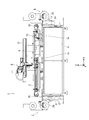
- FIG. 2 is a side view of the peeling device 1 viewed from a front side in a Y direction in FIG. 1.
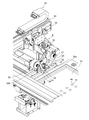
- FIG. 2 is an enlarged perspective view showing a peeling head 6 shown in FIG. 1.
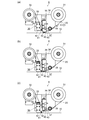
- FIG. 3 is an explanatory diagram illustrating a configuration and an operation of a peeling head 6.
- FIG. 3 is a view showing a flexible laminated substrate 2 which is an example of a laminated substrate as a work to be peeled.
- FIG. 3 is a process flow chart showing main steps of a peeling method according to the embodiment.
- FIG. 4 is an explanatory diagram illustrating main steps of a peeling method according to the embodiment.
- a peeling device 1 and a peeling method according to an embodiment of the present invention will be described with reference to FIGS.
- a flexible laminated substrate 2 will be described as an example of a laminated substrate that is a work.
- FIG. 1 is a perspective view showing a schematic configuration of the peeling device 1 according to the embodiment
- FIG. 2 is a front view of the peeling device 1 as viewed from the near side in the Y direction of FIG.
- FIG. 1 omits illustration of the flexible laminated substrate 2.
- the transport direction of the flexible laminated substrate 2 is the X direction (or X axis)
- the direction orthogonal to the X direction is the Y direction (or Y axis)
- the direction perpendicular to the XY plane is the Z direction. Or, it is described as a vertical direction.
- the peeling device 1 includes a peeling head 6 on an upper portion of a base pedestal 5, a substrate winding roll unit 7 that is disposed at both ends in the X direction and transports the flexible laminated substrate 2, and And a substrate delivery roll unit 8.
- a table 9 (see FIG. 2) for mounting and holding the flexible laminated substrate 2 and a metal mask 10 disposed above the table 9 are provided between the substrate winding unit 7 and the substrate delivery roll unit 8. And are arranged.
- the table 9 is raised by a table elevating mechanism (not shown) to a position where the flexible laminated substrate 2 comes into contact with the metal mask 10 during the peeling operation.
- the metal mask 10 is fixed to a metal mask fixing frame 11 by a plurality of mask fixing tools 12.
- a plurality of openings 13 are provided in the metal mask 10.
- the opening 13 shown in FIG. 1 is different from the actual one in arrangement and shape, and indicates the existence.
- the metal mask 10 can be moved in the X direction and the Y direction by the X-axis drive mechanism 14 and the Y-axis drive mechanism 15, and a portion 46 (see FIG. 5) to be peeled of the flexible laminated substrate 2 and an opening 13 with respect to the position in the plane direction.
- the position correction includes correction of an angle (posture) with respect to the X axis or the Y axis.
- the position correction is performed by image processing based on the detection results of the pair of detection cameras 16 arranged on both sides of the peeling head 6 in the Y direction.
- the detection camera 16 is an imaging device such as a CCD camera.
- the alignment mechanism 18 includes the X-axis drive mechanism 14, the Y-axis drive mechanism 15, and the detection camera 16.
- the peeling device 1 has a peeling head driving mechanism 19.
- the peeling head driving mechanism 19 has a head X-axis driving mechanism 21 that moves the peeling head 6 in the X direction, and a head Y-axis driving mechanism 22 that moves the peeling head 6 in the Y direction.
- Both the head X-axis drive mechanism 21 and the head Y-axis drive mechanism 22 operate by a well-known ball screw mechanism.
- a well-known ball screw mechanism can be used, and a description thereof will be omitted.
- the substrate winding roll unit 7 includes a substrate winding roll 28, a winding dancer roller 27, and an exit roller 26.
- the substrate delivery roll unit 8 has a substrate delivery roll 23, a delivery dancer roller 24, and an entrance roller 25.
- the flexible laminated substrate 2 is stretched between a substrate delivery roll unit 8 and a substrate take-up roll unit 7.
- the substrate take-up roll 28 is a drive roll
- the substrate delivery roll 23 is a driven roll.
- the flexible laminated substrate 2 is delivered from a substrate delivery roll 23, passed through a gap between the table 9 and the metal mask 10 via a dancer roller 24 and an entrance roller 25, to an exit roller 26, and is taken up by a winding dancer.
- the substrate is taken up by a substrate take-up roll 28 via a roller 27.
- the flexible laminated substrate 2 is stretched without slack between the substrate sending roll 23 and the substrate winding roll 28.
- the flexible laminated substrate 2 is vacuum-adsorbed to the table 9 during the peeling operation.
- the transport direction of the flexible laminated substrate 2 is indicated by an arrow.
- a power supply device and a control unit for controlling the entire driving of the peeling device 1 are stored inside the base frame 5.
- FIG. 3 is a perspective view showing the peeling head 6 in an enlarged manner.
- the peeling head 6 includes an adhesive tape winding roll 30 for winding the adhesive tape 20, an adhesive tape sending roll 31 for sending the adhesive tape 20, and a gap between the adhesive tape winding roll 30 and the adhesive tape sending roll 31.
- a pressing roller 32 is provided to press the adhesive tape 20 against the flexible laminated substrate 2 (see FIGS. 2 and 7).
- the adhesive tape take-up roll 30, the adhesive tape delivery roll 31, and the pressing roller 32 are attached to a head body 38 (see FIG. 4).
- the peeling head 6 shown in FIG. 3 shows a state before the peeling device 1 is started.
- the adhesive tape take-up roll 30, the pressing roller 32, and the adhesive tape delivery roll 31 are arranged linearly in a plan view.
- the adhesive tape take-up roll 30 is a driving roll
- the adhesive tape delivery roll 31 is a driven roll.
- the peeling head 6 further includes a ⁇ -axis drive mechanism 33 that rotates along the upper surface 10a of the metal mask 10 without changing the arrangement of the adhesive tape take-up roll 30, the pressing roller 32, and the adhesive tape delivery roll 31. .
- the ⁇ -axis drive mechanism 33 adjusts the angle (posture) in the plane direction with respect to the arrangement of the openings 13 of the pressing roller 32.
- the peeling head 6 can be moved up and down with respect to the metal mask 10 by a vertically moving drive mechanism 34.
- the surface that contacts the pressing roller 32 is referred to as a non-adhesive layer 20a, and the opposite surface is referred to as an adhesive layer 20b.
- the peeling head 6 includes a pressing roller elevating mechanism 35 for elevating and lowering the pressing roller 32 with respect to the upper surface of the metal mask 10, a mask pressing mechanism 36 for preventing the metal mask 10 from floating, and an excessive unwinding of the adhesive tape 20. And a stopper mechanism 37 for suppressing the loosening due to.
- the detailed configurations and operations of the pressing roller 32, the pressing roller lifting mechanism 35, the mask pressing mechanism 36, and the stopper mechanism 37 will be described later with reference to FIG.
- FIG. 4 is an explanatory diagram illustrating the configuration and operation of the peeling head 6.
- the configuration and operation of the peeling head 6 will be described, and details of the peeling operation will be described later with reference to FIGS. 4A illustrates a state during the peeling operation
- FIG. 4B illustrates a state immediately before the peeling operation is completed and the pressing roller 32 is raised
- FIG. 4C illustrates a state where the peeling operation is completed and the pressing roller 32 is raised. Immediately after it is shown.
- the pressing roller 32 presses the metal mask 10 during the peeling operation.
- the adhesive tape 20 is stretched from the adhesive tape delivery roll 31 to the intermediate roller 39, the stopper roller 40, and the pressing roller 32 in this order, and is wound around the adhesive tape winding roll 30 without slack.
- the mask holding mechanism 36 has a mask holding roller 41 and a mask holding roller driving unit 42 that moves the mask holding roller 41 up and down with respect to the metal mask 10.
- the mask pressing roller 41 is disposed immediately adjacent to the pressure roller-32 on the side of the adhesive tape winding roll 30. It is preferable that the length of the mask pressing roller 41 in the axial direction is equal to or longer than the length of the pressing roller 32, and the mask pressing roller 41 does not necessarily have to have flexibility.
- the mask pressing roller 41 projects from the lower end of the mask pressing roller driving unit 42. During the peeling operation, the mask pressing roller 41 is on standby at a position where it does not contact the metal mask 10.
- the intermediate roller 39 has a function of reducing the slack of the adhesive tape between the adhesive tape delivery roll 31 and the pressing roller 32 and applying an appropriate brake that does not affect winding.
- the pressing roller 32, the stopper roller 40, and the stopper mechanism 37 are attached to the pressing roller elevating mechanism 35, and are configured to lower or ascend with respect to the metal mask 10 by the pressing roller elevating mechanism 35.
- the stopper mechanism 37 has a stopper roller 40 and a stopper portion 43.
- the stopper 43 can be moved up and down independently of the pressing roller elevating mechanism 35.
- the stopper roller 40 and the stopper portion 43 are separated from each other, and the adhesive tape 20 can be wound by the adhesive tape winding roll 30.
- the moving direction of the peeling head 6 is indicated by a thick arrow
- the moving direction of the adhesive tape 20 is indicated by a thin arrow.
- the pressing roller 32 presses the adhesive tape 20 against the metal mask 10 and uses the flexibility of the pressing roller 6 to adhere the adhesive tape 20 to the uppermost substrate 48 in the opening 13 provided in the metal mask 10. Press the layer 20b (see FIG. 7).
- the pressing roller 6 rolls while moving in the direction of the thick arrow, and peels off the uppermost substrate 48 in the opening 13 from the lower substrate 47.
- the peeling head 6 moves in the direction of the arrow shown in the peeling target range 49 in FIG.
- FIG. 4B shows a state immediately before the peeling operation is completed and the pressing roller 32 is raised.
- the structure of each mechanism and each roller has been described with reference to FIG.
- the horizontal movement of the peeling head 6 is stopped, the stopper portion 43 descends toward the stopper roller 40, and the adhesive tape 20 is pressed against the stopper roller 40 to apply a brake to the adhesive tape 20.
- the adhesive tape 20 is not loosened due to the tension between the adhesive tape take-up roll 30 and the stopper roller 40.
- the mask pressing roller 41 descends until the mask pressing roller driving unit 42 presses the metal mask 10.
- FIG. 4C shows a state immediately after the peeling operation is completed and the pressing roller 32 is raised.
- the structure of each mechanism and each roller has been described with reference to FIG.
- the pressing roller 6 is raised until it is separated from the metal mask.
- the mask pressing roller 41 presses the metal mask 10.
- the pressing of the metal mask 10 by the mask pressing roller 41 continues until the pressing roller 6 stops rising.
- the stopper mechanism 37 applies a brake to the adhesive tape 20 until the next peeling operation is started, and suppresses the looseness of the adhesive tape 20.
- illustration is omitted, when the pressing roller 32 is raised, the mask pressing roller 41 is raised to the position shown in FIG. Note that there is no vertical movement of the peeling head 6 in each step shown in FIGS. 4 (a) to 4 (c). The details of the peeling operation and the peeling method by the peeling head 6 described above will be described with reference to FIGS.
- FIG. 5 is a view showing a flexible laminated substrate 2 which is an example of a laminated substrate as a workpiece to be peeled.
- FIG. 5A is a plan view showing a part of the flexible laminated substrate 2, showing an example of the arrangement of the portions 46 (46 a, 46 b, 46 c) of the uppermost substrate 48 and the openings 13 of the metal mask 10. Represents.
- the part to be peeled is a range where the uppermost substrate 48 is to be peeled, and is defined by the openings 13 (13a, 13b, 13c) of the metal mask 10.
- FIG. 5A are for explaining the peeling operation and schematically show an example different from the actual one, and the separation target portions 46 are arranged more densely. In some cases, they may be arranged sparsely.
- FIG. 5B is a cross-sectional view illustrating an example of the configuration of the flexible laminated substrate 2. In FIG. 5B, the thickness is exaggerated.
- the parts 46a, 46b and 46c to be peeled are collectively referred to as a part 46 to be peeled, and the openings 13a, 13b and 13c are collectively referred to as an opening 13.
- the flexible laminated substrate 2 is composed of a plurality of layers of substrates.
- the flexible laminated substrate 2 includes a lower substrate 47 and an uppermost substrate 48 bonded to the lower substrate 47 with a thermosetting resin or the like.
- the case where the lower substrate 47 is a multilayer substrate having two or more layers is also included.
- a functional pattern such as a conductive pattern or an electrode is formed on the upper surface, the lower surface, or both upper and lower surfaces of each of the uppermost substrate 48 and the lower substrate 47, they are not shown.
- the uppermost substrate 48 may not have a functional pattern.
- the thickness of the uppermost substrate 4 is, for example, 10 ⁇ m to 80 ⁇ m, and the total thickness of the flexible laminated substrate 2 is not particularly limited as long as it can be wound around the substrate take-up roll 28 and the substrate delivery roll 23.
- the laminated substrate is not limited to the tape-shaped flexible laminated substrate 2 but can be adapted to a single-layer laminated substrate.
- the metal mask 10 and the opening 13 of the metal mask 10 are represented by two-dot chain lines.
- a group A in which four separation target portions 46 a (openings 13 a) having the same shape and the same size are arranged in parallel to the feeding direction (thick arrow) of the flexible laminated substrate 2.
- Group B in which three portions 46b (openings 13b) having substantially the same shape and the same size are arranged orthogonally to the array of the group A, and the portion 46c to be peeled having the same shape and the same size as the array of the group A
- Group C arranged two obliquely.
- the thin arrows in the peeling target range 49 in FIG. 5A indicate the peeling order.
- the thickness of the metal mask 10 is about 30 ⁇ m to 80 ⁇ m, but is not limited.
- a region where the pressing roller 32 moves while pressing the metal mask 10 is referred to as a movement locus.
- the axial length of the pressing roller 32 is longer than the maximum width of the openings 13a, 13b, 13c in a direction orthogonal to the moving direction of the pressing roller 32. Therefore, if the size of the opening 13 in the group A, the group B, and the group C is within the length of the pressing roller 32, there is no need to replace the pressing roller 32.
- the adhesive tape 20 has a width that does not span the openings 13 arranged outside the movement locus of the pressing roller 32. That is, the adhesive tape 20 does not span the opening 13b of the group B when peeling the group A, and the adhesive tape 20 does not span the opening 13c of the group C when peeling the group B.
- the peeling device 1 described above is a peeling device that peels off the part 46 to be peeled of the uppermost substrate 48 of the flexible laminated substrate 2 as the laminated substrate from the lower substrate 47 by the adhesive force of the adhesive tape 20.
- the peeling apparatus 1 includes a metal mask fixing frame 11 for holding and fixing a metal mask 10 having an opening 13 defining a range of a part 46 to be peeled of an uppermost substrate 48, and an adhesive tape 20 from an upper surface 10 a of the metal mask 10.
- a pressure roller 32 for pressing the layer 20 b against the uppermost substrate 48 in the opening 13, an adhesive tape winding roll 30 for winding the adhesive tape 20, and a peeling head 6 having an adhesive tape sending roll 31 for sending the adhesive tape 20. have.
- the peeling device 1 has a peeling head driving mechanism 19 that can switch the moving direction of the peeling head 6 and moves the pressing roller 32 while pressing the adhesive layer 20b against the uppermost substrate 48.
- the pressure roller 32 is attached to the uppermost substrate 48 with the adhesive layer 20b of the adhesive tape 20 adhered to the opening 13 (13a, 13b, 13c) of the metal mask 10. Is moved, it is possible to peel off while cutting the portions 46 (46a, 46b, 46c) to be peeled at the edge 50 (see FIG. 7B) on the lower surface side of the opening 13. Further, since the moving direction of the peeling head 32 can be switched, the peeling target portion 46 can be peeled from the lower substrate 47 regardless of the size, shape and arrangement of the peeling target portion 46.
- the adhesive tape take-up roll 30 and the adhesive tape delivery roll 31 are linearly arranged in a plan view with the pressing roller 32 interposed therebetween.
- the peeling head 6 includes a ⁇ -axis driving mechanism 33 that rotates the pressing roller 32, the adhesive tape take-up roll 30, and the adhesive tape delivery roll 31 along the upper surface 10 a of the metal mask 10, and the pressing roller 32 rotates the upper surface of the metal mask 10. And a pressing roller raising / lowering mechanism 35 for raising and lowering in a vertical direction.
- the peeling head 6 includes the pressing roller 32, the adhesive tape take-up roll 30, and the adhesive tape unwinding roll in the arrangement of the openings 13 (13 a, 13 b, 13 c) of the metal mask 10, in other words, the part 46 to be peeled. (46a, 46b, 46c), the uppermost substrate 48 can be moved to the lower layer irrespective of the size, shape and arrangement of the part 46 to be peeled, which is a specific portion of the uppermost substrate 48. Peeling from the substrate 47 becomes possible. Further, when the pressing roller 32 is raised, the adhesive tape 20 follows the pressing roller 32 and separates upward from the metal mask 10, so that the peeling target portion 46 is moved from the uppermost substrate 48 to the edge portion 50 of the opening 13. And can be separated.
- the pressing roller 32 has flexibility, and its axial length is longer than the maximum width of the opening 13 in a direction orthogonal to the moving direction of the pressing roller 32. The width does not span the openings 13 arranged outside the trajectory. Since the pressing roller 32 has flexibility, the pressure-sensitive adhesive tape 20 can be pressed from the upper surface 10 a of the metal mask to the uppermost substrate 48 in the opening 13. Therefore, if the opening 13 is within the range of the length of the pressing roller 32, the separation target portion 46 can be separated regardless of the shape and size of the separation target portion. Further, since the adhesive tape 20 does not span the opening outside the movement locus of the pressing roller 13, only the uppermost substrate 48 of the part 46 to be peeled within the range of the movement locus can be peeled.
- the pressing roller 32 peels the peeling target portion 46 by the adhesive force of the adhesive tape 20 while pressing the adhesive tape 20 against the peeling target portion 46 while moving, and the end of the opening 13 in the moving direction side of the pressing roller 32.
- the pressing roller 32 that is, the adhesive tape 20
- the adhesive tape winding roll 30 is controlled so as to wind the adhesive tape 20 in synchronization with the peeling operation in which the pressing roller 32 presses the adhesive tape 20 against the peeling target portion 46 and moves. In this way, a new non-adhesive portion of the adhesive layer 20b can always adhere to the portion 46 to be peeled during the peeling operation. Further, since the separated part 46 to be separated (referred to as an uppermost substrate piece 48a, see FIG. 7) is moved to a position away from the next part to be separated, the uppermost substrate piece 48a is moved to the next peeling operation. It is possible to prevent the obstruction.
- the peeling head 6 has a stopper mechanism 37 that is disposed immediately adjacent to the pressure-feed roller 32 on the side of the pressure-sensitive adhesive tape delivery roll 31 and applies a brake to the pressure-sensitive adhesive tape 20 during the upward movement of the pressure roller 32.
- the adhesive tape winding roll 30 and the stopper mechanism 37 apply tension to the adhesive tape 20 to prevent the adhesive tape 20 from being loosened.
- the portion to be peeled can be reliably separated from the uppermost substrate 48. Further, it becomes possible to prevent the adhesive tape 20 from sticking to the metal mask 10 due to loosening.
- the peeling head 6 has a mask pressing mechanism 36 which is disposed immediately adjacent to the pressure roller 32 on the side of the adhesive tape take-up roll 31 and presses the metal mask 10 while the pressing roller 32 is moving up. If the pressing roller 32 is raised in a state where the metal mask 10 is pressed by the mask pressing mechanism 36 in this manner, the metal mask 10 can be prevented from floating due to the adhesive force of the adhesive tape 20, and the metal mask 10 and the uppermost substrate Since there is no gap between the uppermost substrate 48 and the uppermost substrate 48, the separation target portion 46 can be more reliably cut and separated.
- the metal mask fixing frame 11 further includes an X-axis drive mechanism 14 and a Y-axis drive mechanism 15 as an alignment mechanism 18 for correcting the position of the opening 13 and the portion 46 to be peeled.
- an X-axis drive mechanism 14 and a Y-axis drive mechanism 15 as an alignment mechanism 18 for correcting the position of the opening 13 and the portion 46 to be peeled.
- the peeling device 1 at least a member to which the adhesive tape 20 comes into contact is subjected to a non-adhesive treatment.
- a non-adhesive treatment to a member that comes into contact with the adhesive tape 20, it is possible to eliminate a problem caused by the adhesive tape 20 sticking.
- the adhesive tape take-up roll 30, the pressing roller 32, the stopper roller 40, the stopper portion 43, the intermediate roller 39, the adhesive tape delivery roll 31, and the like are targets.
- the pressure-sensitive adhesive layer 20b is pressed against the periphery of the opening 13 of the metal mask 10 by the pressing roller during the peeling operation.
- the metal mask upper surface 20a it is possible to prevent the adhesive layer 20b from sticking to the metal mask 10.
- FIG. 6 is a process flow chart showing main steps of the stripping method according to the embodiment
- FIG. 7 is an explanatory diagram showing main steps of the stripping method.
- FIG. 7 is a schematic diagram in which the scale and shape of each part are exaggerated for easy understanding.
- 7A shows a state immediately before the start of the peeling operation
- FIG. 7B shows a state at the end of the peeling operation
- FIG. 7C shows a separating operation.
- a peeling operation of the group A of the flexible laminated substrate 2 shown in FIG. 5A as a work to be peeled will be described as a representative example.
- the peeling range 49 of the flexible laminated substrate 2 is transported to a predetermined position on the table 9 and is adsorbed on the table 9, and then the flexible laminated substrate 2 is raised to a position where it comes into contact with the metal mask 10 (step S1).
- the vertical movement of the flexible laminated substrate 2 is controlled by a table elevating mechanism (not shown).
- the positions of the opening 13 of the metal mask 10 and the portion 46 to be separated of the uppermost substrate 48 are corrected (step S2).
- the position correction is performed by detecting the alignment mark provided on the uppermost substrate 48 and the alignment mark provided on the metal mask 10 by the detection camera 16, and determining the amount of the deviation by using the X-axis drive mechanism 14 and the Y-axis. This is performed by adjusting the position of the metal mask 10 to the uppermost substrate 48 by the shaft driving mechanism 15.
- the alignment mark of the metal mask 10 may be a plurality of openings 13.
- step S3 the position and the moving direction of the pressing roller 32 are adjusted to the arrangement of the portion 46 to be peeled.
- the peeling is performed in the order of the position P1, the position P2, the position P3, and the position P4 shown in FIG.
- the axial direction of the pressing roller 32 is set to a direction orthogonal to the transport direction of the flexible laminated substrate 2, and the left side of the opening 13a at the position P1 in the drawing (
- the position of the pressing roller 32 is indicated by a two-dot chain line in the drawing.
- the operation in step S3 is executed by the head X-axis drive mechanism 21, the head Y-axis drive mechanism 22, and the ⁇ -axis drive mechanism 33.
- the pressing roller 32 descends until it presses the metal mask 10, and the pressing roller 32 is further moved to the opening 13a to move the adhesive tape 20 to the uppermost layer in the opening 13a.
- the substrate 48 is pressed against the separation target portion 46a (step S4).
- the moving direction of the pressing roller 32 is indicated by a thick arrow.
- the pressing roller 32 is deformed by its own flexibility when pressing the metal mask upper surface 10a, and can press the adhesive tape 20 against the uppermost substrate 48 in the opening 13a.
- step S4 as the position before the peeling operation of the pressing roller 32, the position where the pressing roller 32 spans the opening 13a or the position on the metal mask 10 slightly away from the left end of the opening 13a in the drawing is illustrated. It may be a position.
- the mask pressing roller 41 is at a position separated from the metal mask 10. Further, the stopper portion 43 is separated from the stopper roller 40 and does not apply a brake to the adhesive tape 20.
- the pressing roller 32 is moved in the direction of the thick arrow to peel off the portion 46a to be peeled off of the uppermost substrate 48 (Step S5).
- the uppermost substrate 48 is strongly adhered by the adhesive force of the adhesive tape 20, and the pressing roller 32 moves in the direction of the thick arrow, so that the pressing roller 32 is pressed by the edge 50 of the opening 13a of the metal mask 10.
- the exfoliation is performed while cutting the exfoliation target portion 46a on the 32 movement path.
- the edge portions 50 are formed at the lower side corners of the four sides of the opening 13a.
- the uppermost substrate 48 adhered to the adhesive tape 20 is taken up by the substrate take-up roll 30 in a direction opposite to the moving direction of the pressing roller 32 in synchronization with the movement of the pressing roller 32, and is indicated by a dotted arrow in the drawing. Move to.
- the uppermost substrate 48 is peeled off while being cut at the three edge portions 50 of the opening 13a.
- the pressing roller 32 rolls in the direction of the arrow as it moves. Note that the pressing roller 32 may be moved until it is placed on the metal mask 10 beyond the right end in the drawing of the opening 13a. In the state shown in FIG.
- the mask pressing roller 41 is separated from the metal mask 10, and the stopper portion 43 applies the adhesive tape 20 to the stopper roller 40.
- the adhesive tape 20 is pressed to apply a brake, and tension is applied to the adhesive tape 20 between itself and the adhesive tape take-up roll 30 so that the adhesive tape 20 is not loosened.
- the pressing roller 32 is raised to separate the part 46a to be peeled from the uppermost substrate 48 (Step S6).
- the portion 46a to be peeled off is peeled off by the adhesive force of the adhesive tape 20 that rises with the pressing roller 32, cut off at the edge 50 at the right end of the opening 13a in the drawing, and separated from the uppermost substrate 48.
- the stopper 43 moves up in conjunction with the pressing roller 32 with the adhesive tape 20 braked between the stopper 43 and the stopper roller 40.
- the mask pressing roller 41 descends and presses the metal mask 10.
- the metal mask 10 does not float from the flexible multilayer substrate 2 when cutting and separating the separation target portion 46a. Since there is no gap between the metal mask 10 and the uppermost substrate 48, the uppermost substrate piece 48a can be reliably separated from the uppermost substrate 48.
- the pressure-sensitive adhesive tape take-up roll 30 takes up the pressure-sensitive adhesive tape 20 for the distance that the pressing roll 32 has risen so that the pressure-sensitive adhesive tape 20 does not loosen.
- the pressing roller 32 is moved to the position P2 on the right side of the position P1 to start the peeling operation. Specifically, the peeling head 6 is driven to move the pressing roller 32 to the position P2 (Step S7), and Steps S4 to S7 are executed. Next, in the order of the position P3 and the position P4, the separation target portion 46a in the opening 13a is separated and separated in order by repeating the above-described steps S4 to S7. In addition, the peeling order may be performed in the order from the position P4 to the position P1, and can be appropriately changed depending on the arrangement of the peeling target portions 46.
- the peeling head 6 is moved to the group B, which is the next group to be peeled (step 8).
- the steps S3 to S7 are repeated in the order of the position P5, the position P6, and the position P7 to peel the part 46b to be peeled in the opening 13b.
- the peeling head 6 is rotated 90 degrees from the peeling operation posture in the group A. That is, the arrangement of the adhesive tape take-up roll 30, the pressing roll 32, and the adhesive tape delivery roll 31 is set to a posture orthogonal to the transport direction of the flexible laminated substrate 2, and is pressed to a predetermined position below the opening 13b at the position P5 in the drawing.
- the roll 32 is arranged (Step P3). Then, while moving the pressing roll 32 upward in the drawing, the separation target portion 46b in the opening 13b is separated and separated. That is, the steps S4 to S7 are repeated, and the peeling operation is repeated at the positions P6 and P7. After all the peeling operations of the group B are completed, the peeling head 6 is moved to the next group C to be peeled, and the peeling / separating operation is performed in the group C. In the group B, the peeling order may be performed in the order from the position P7 to the position P5, and can be appropriately changed depending on the arrangement of the peeling target portions 46.
- the separation operation is performed as if the positions P8 and P9 are independent. Execute. That is, after the peeling at the position P8 is performed, the peeling operation is performed by moving the peeling head 6 toward the position P9. In the example shown in FIG. 5A, the attitude of the peeling head 6 does not need to be changed with respect to the peeling operation of the group B.
- the peeling operation of the group C can follow the peeling operation of the group A and the group B.
- the pressing roll 32 is disposed at a predetermined position above the opening 13c at the position P8 in the drawing.
- the separation target portion 46c in the opening 13c is separated and separated. Then, the pressing roller 32 is moved to the position P9, and the steps S4 to S6 are repeated to repeat the peeling / separating operation at the position P9.
- the peeling at the position P8 may be performed after the position P9.
- the peeling head 6 After the peeling of the groups A, B, and C is completed, that is, after all the peeling of the peeling target range 49 is completed, the peeling head 6 returns and stands by before the activation of the peeling device 1 shown in FIG. Then, the table 9 is lowered, and the flexible laminated substrate 2 is transported by the substrate take-up roll 28 until the next peeling target position 49 reaches a predetermined position, and steps S1 to S8 are repeated.
- the transport of the flexible laminated substrate 2, the operation of the peeling head 6, the operations of the pressing roller 32, the substrate winding roll 28, the adhesive tape winding roll 30, the stopper roller 40, and the stopper portion 43 are flexible. It is controlled by a program adapted to the arrangement of the portion 46 to be separated of the laminated substrate 2.
- the peeling order of the group A, the group B, and the group C can be changed to, for example, the group C, the group B, and the group A.
- the peeling method described above is a peeling method in which the peeling target portion 46 of the uppermost substrate 48 is peeled from the lower substrate 47 by the adhesive force of the adhesive tape 20 using the peeling device 1.
- the peeling method includes a step of transporting the flexible laminated substrate 2 which is a laminated substrate as a work to a predetermined position and elevating the flexible laminated substrate 2 to a position where the flexible laminated substrate 2 comes into contact with the metal mask 10.
- the lower surface of the opening 13 is moved by moving the pressing roller 32 in the opening 13 of the metal mask 10 while pressing the adhesive layer 20 b of the adhesive tape 20 against the uppermost substrate 48. It is possible to peel off the part 46 to be peeled while cutting it at the edge 50 on the side.
- the pressing roller 32 reaches the end of the opening 13 in the direction of movement of the pressing roller, the pressing roller 32 is raised to cut the remaining connection portion of the portion to be peeled off at the edge 50 of the opening 13, and 46 can be separated from the uppermost substrate 48.
- the flexible laminated substrate 2 as a laminated substrate has a plurality of portions 46 to be separated within a range 49 to be separated, and the metal mask 10 has openings 13 corresponding to the shape and arrangement of the portions 46 to be separated.
- the pressing position and moving direction of the pressing roller 32 can be switched according to the arrangement of the openings 13.
- this appearance inspection can be performed by image processing using an inspection camera or the like, or may be a visual inspection.
- the present invention is not limited to the above-described embodiment, and includes modifications and improvements as long as the object of the present invention can be achieved.
- the flexible laminated substrate 2 having a two-layer configuration has been described as an example of the workpiece to be peeled.
- the lower substrate 47 is a multilayer substrate, a rigid substrate, or the like, or a single-layer laminated substrate, or The present invention can be applied to a semiconductor wafer, a display device, or the like that peels off only a specific portion of a protective film.
- X-axis drive mechanism 15: Y-axis drive mechanism, 16: detection camera, 18: alignment mechanism, 19: peeling head drive mechanism, 20: adhesive tape, 20a: non-adhesive layer, 20b: adhesive layer, 30: adhesive tape winding Take-up roll, 31: adhesive tape delivery roll, 32: pressing roller, 33: ⁇ -axis driving mechanism, 35: pressing roller elevating mechanism, 36: mask pressing mechanism, 37: stopper mechanism, 46 (46a, 46b, 46c) Part to be peeled, 47 ... Lower layer substrate, 48 ... Top layer substrate, 49 ... Range to be peeled, 50 ... Edge part
Landscapes
- Folding Of Thin Sheet-Like Materials, Special Discharging Devices, And Others (AREA)
- Container, Conveyance, Adherence, Positioning, Of Wafer (AREA)
Abstract
本発明の剥離装置1は、最上層基板48の剥離対象部分46の範囲を規定する開口部13を有するメタルマスク10を保持固定するメタルマスク固定枠11と、メタルマスク10の上面10aから粘着テープ20の粘着層20bを開口部13内の最上層基板48に押圧する押圧ローラ32と、剥離ヘッド6とを有している。さらに、剥離装置1は、剥離ヘッド6の移動方向を切り換えることが可能、かつ最上層基板48に粘着層20bを押圧した状態で押圧ローラ32を移動させる剥離ヘッド駆動機構19と、を有することを特徴とする。 本発明の剥離装置1によれば、剥離対象部分46の大きさ、形状及び配置に関わらず下層基板47から最上層基板48の剥離対象部分46を下層基板47から剥離し、最上層基板48から剥離対象部分46を切断分離することができる。
Description
本発明は、剥離装置及び剥離方法に関する。
回路基板(フレキシブル回路基板を含む)、半導体ウエハやディスプレイ装置などにおいて、機能面を保護するために製造過程ではカバーフィルム、いわゆる保護フィルムを貼り合せておき、カバーフィルムを剥離して次工程に移行することが一般的に行われている。カバーフィルムを剥離する手段としては、粘着テープの粘着面をカバーフィルムに押圧して粘着テープの粘着力によってカバーフィルムを剥離する装置及び剥離方法が従来から採用されている。回路基板や半導体ウエハとほぼ同じサイズのカバーフィルムを剥離する場合には、単純に粘着テープをカバーフィルムに押圧して粘着テープを引上げたり、巻き上げたりすることによってカバーフィルムを剥離することが容易に可能である。しかし、このような剥離装置や剥離方法では、カバーフィルムのうちの特定範囲のみを剥離することは困難であった。
特許文献1には、回路基板などに貼り合わされたカバーフィルムの特定箇所のみを剥離する剥離装置が開示されている。特許文献1に記載された剥離装置は、剥離対象部分の周囲にハーフカットによって切り込みを入れ、この切り込みで囲まれた内側に粘着テープの粘着面を押圧部材によって押圧し、次いで、押圧部材を粘着テープと共に回路基板から離間させて剥離対象部分のカバーフィルムを剥離する、というものである。
特許文献1に記載の剥離装置は、カバーフィルムの剥離対象部分の周囲にハーフカットによって切り込みを入れ、切り込みで囲まれたカバーフィルムの剥離対象部分に粘着テープを押圧して粘着テープの粘着力でカバーフィルムを下層基板から剥離する装置である。従って、下層の回路基板などに剥離する部分と剥離しない部分とに跨って導電パターンや電極などの機能パターンが形成されている場合には、機能パターン上のカバーフィルムに切り込みを入れることは機能パターンに損傷を与える恐れがあるので困難である。特許文献1に記載の剥離装置では、切り込みがない特定の剥離対象部分のみを剥離することはできないという課題がある。
又、特許文献1に記載の剥離装置は、ハーフカットされた剥離対象部分の表面積の80%以上、かつ100%以下の面積に対して均一に粘着テープを押圧部材で押圧し、押圧部材を回路基板から離間させてカバーフィルムを剥離するというものである。従って、回路基板が積層基板(フレキシブル積層基板)であって、最上層基板を下層基板から剥離するような場合、しかも剥離対象部分の面積が大きくなったり、剥離対象部分が縦横比の大きい形状であったりすると、押圧部材の単純な昇降動作では、剥離できなかったり、剥離の際に回路基板が反ってしまったりするなどの課題がある。
さらに、特許文献1に記載の剥離装置は、剥離ヘッド(作業ヘッド)が一方向に直線的に移動する構成であるから、最上層基板上に複数の剥離対象部分が散在する場合などには対応できない。しかも、剥離対象部分が複数種類の形状で構成される場合などでは、押圧部材の押圧平面の向きや形状を剥離対象部分に合わせて切換えなければならず生産性が著しく悪くなるという課題がある。
そこで、本発明は、このような課題の少なくとも一つを解決するためになされたものであり、剥離対象部分の大きさ、形状及び配置に関わらず下層基板から最上層基板の剥離対象部分を下層基板から剥離し、最上層基板から剥離対象部分を切断分離することが可能な剥離装置及び剥離方法を提供しようとするものである。
[1]本発明の剥離装置は、積層基板の最上層基板の剥離対象部分を粘着テープの粘着力で下層基板から剥離する剥離装置であって、前記最上層基板の上面側に配置され前記剥離対象部分の範囲を規定する開口部を有するメタルマスクを保持固定するメタルマスク固定枠と、前記メタルマスクの上面から前記粘着テープの粘着層を前記開口部内の前記最上層基板に押圧する押圧ローラ、前記粘着テープを巻き取る粘着テープ巻取りロール及び前記粘着テープを送り出す粘着テープ送出しロールを有する剥離ヘッドと、前記剥離ヘッドの移動方向を切り換えることが可能、かつ前記最上層基板に前記粘着層を押圧した状態で前記押圧ローラを移動させる剥離ヘッド駆動機構と、を有することを特徴とする。
本発明の剥離装置によれば、メタルマスクの開口部内において、最上層基板に粘着テープの粘着層を粘着した状態で押圧ローラが移動することによって、メタルマスクの開口部の下面側のエッジ部で剥離対象部分を切断しながら剥離していくことができる。さらに、剥離ヘッドは、移動方向を切り換えることが可能となっていることから、剥離対象部分の大きさ、形状及び配置に関わらず下層基板から剥離対象部分を剥離し、最上層基板から剥離対象部分を切断分離することが可能となる。
[2]本発明の剥離装置においては、前記粘着テープ巻取りロールと前記粘着テープ送出しロールは、前記押圧ローラを挟んで平面視直線的に配置されており、前記剥離ヘッドは、前記押圧ローラ、前記粘着テープ巻取りロール及び前記粘着テープ送出しロールを前記メタルマスクの上面に沿って回転するθ軸駆動機構と、前記押圧ローラを前記メタルマスクの上面に対して鉛直方向に昇降させる押圧ローラ昇降機構と、を有することが好ましい。
剥離ヘッドは、押圧ローラ、粘着テープ巻取りロール及び粘着テープ巻出しりロールをメタルマスクの開口部、つまり剥離対象部分の配列に合わせて移動させことが可能であるから、剥離対象部分の配列に関わらず最上層基板を下層基板から剥離することが可能となる。又、押圧ローラを上昇させれば、粘着テープが押圧ローラに追従してメタルマスクから上方側に上昇し、剥離対象部分を最上層基板から開口部のエッジ部で切断し、確実に切断分離することが可能となる。
[3]本発明の剥離装置においては、前記押圧ローラは可撓性を有しており、軸方向長さが前記押圧ローラの移動方向に対して直交する方向の前記開口部の最大幅よりも長く、前記粘着テープは、前記押圧ローラの移動軌跡外に配列される前記開口部に架からない幅であることが好ましい。
押圧ローラは可撓性を有しており、押圧ローラで剥離対象の開口部の縁周囲を押えながら剥離することから、メタルマスクの浮き上がりがなく、剥離対象部分の切断及び剥離を行うことが可能となる。又、押圧ローラの長さの範囲にあれば剥離対象部分の形状やサイズに関わらず剥離対象部分を剥離することが可能となる。粘着テープは押圧ローラの移動軌跡外にある開口部には架からないことから、移動軌跡の範囲にある最上層基板のみを剥離することが可能となる。
[4]本発明の剥離装置においては、前記押圧ローラは、前記剥離対象部分に前記粘着テープを押圧して移動しつつ前記粘着テープの粘着力で剥離対象部分を剥離していき、前記開口部のエッジ部で前記押圧ローラの移動方向側端部で前記粘着テープを前記積層基板から離れる方向に上昇させるように制御されることをことが好ましい。
このように、剥離動作終了後に、押圧ローラを上昇させて粘着テープを引き上げることによって、剥離対象部分を最上層基板からより一層確実に切断・分離することが可能となる。
[5]本発明の剥離装置においては、前記粘着テープ巻取りロールは、前記押圧ローラが前記粘着テープを前記剥離対象部分に押圧して移動する剥離動作に同期して前記粘着テープを巻き取るように制御されることが好ましい。
このようにすれば、剥離動作中に常に粘着層の新しい部分が剥離対象部分に粘着することが可能となり、さらに、分離した剥離対象部分(以降、最上層基板片と記載する)を次の剥離対象部分から離間させることができるから、最上層基板片が次の剥離動作の妨げになることを防ぐことが可能となる。
[6]本発明の剥離装置においては、前記剥離ヘッドは、前記押圧ローラの前記粘着テープ送出しロール側の直近に配置されて前記押圧ローラの上昇動作中に前記粘着テープにブレーキを掛けるストッパー機構を有していることが好ましい。
このように剥離ヘッドを構成すれば、粘着テープ巻取りロールとストッパー機構によって粘着テープに張力を与えて粘着テープが弛むこと防ぎ、押圧ローラが上昇する際に粘着テープが押圧ローラに追従することで確実に剥離対象部分を最上層基板から分離することが可能となる。
[7]本発明の剥離装置においては、前記剥離ヘッドは、前記押圧ローラの前記粘着テープ巻取りロール側の直近に配置されて前記押圧ローラの上昇動作中に前記メタルマスクを押えるマスク押え機構を有していることが好ましい。
このようにマスク押え機構によってメタルマスクを押圧したうえで押圧ローラを上昇させれば、粘着テープの粘着力でメタルマスクが浮きあがることを防止でき、メタルマスクと最上層基板との間に隙間ができないことから剥離対象部分の最上層基板からの切断・分離をより一層確実に行うことが可能となる。
[8]本発明の剥離装置においては、前記メタルマスク固定枠は、前記開口部と前記剥離対象部分との位置補正を行うアライメント機構を有していることが好ましい。
メタルマスクの開口部を所定の剥離対象部分に位置合せすることによって、位置ずれに起因する剥離不良を排除することが可能となる。
[9]本発明の剥離装置においては、少なくとも前記粘着テープが接触する部材には、非粘着処理が施されていることが好ましい。
粘着テープの粘着層が剥離装置、特に剥離ヘッドの構成部材に接触すると、剥離装置の正常な駆動や剥離動作が妨げられることがある。そこで、粘着テープが接触する部材に非粘着処理を施すことによって、粘着テープの粘着に起因する不具合を排除することが可能となる。
[10]本発明の剥離方法は、上記記載の剥離装置を使用して前記最上層基板の剥離対象部分を前記粘着テープの粘着力で前記下層基板から剥離するする剥離方法であって、前記積層基板を所定位置に搬送して前記メタルマスクに当接する位置に上昇させる工程と、前記メタルマスクの開口部と前記剥離対象部分との位置補正を行う工程と、前記押圧ローラの押圧位置及び移動方向を前記剥離対象部分の配列に合わせる工程と、前記押圧ローラを降下し、さらに前記開口部に移動させることにより前記粘着テープを前記開口部内の前記最上層基板に押圧する押圧工程と、前記粘着テープを前記開口部内の前記最上層基板に押圧しつつ前記押圧ローラを移動して前記剥離対象部分を前記開口部のエッジ部で切断しながら剥離する工程と、前記押圧ローラを前記メタルマスクから離間する方向に上昇させて最上層基板片を前記下層基板から分離する工程と、を含むことを特徴とする。
本発明の剥離方法によれば、メタルマスクの開口部内において、最上層基板に粘着テープの粘着層を押圧した状態で押圧ローラを移動することによって、開口部の下面側のエッジ部で剥離対象部分を切断しながら剥離していくことが可能となる。そして、押圧ローラがメタルマスクの開口部の押圧ローラ移動方向端部に達したところで押圧ローラを上昇させて剥離対象部分を開口部のエッジ部で切断し、剥離対象部分を最上層基板から分離することが可能となる。
[11]本発明の剥離方法においては、前記積層基板は剥離対象範囲内に前記剥離対象部分が複数有し、前記メタルマスクは前記剥離対象部分の形状及び配列に対応する開口部を有しており、前記開口部の配列に合わせて前記押圧ローラの押圧位置及び移動方向を切り換えることが好ましい。
このように、剥離対象部分の配列に対応して押圧ローラの位置及び移動方向を切り換えることによって、剥離対象範囲内に複数種類の剥離対象部分があっても連続して剥離を行うことが可能となる。このようにすれば、生産性を極めて高くすることが可能となる。
以下、本発明の実施の形態に係る剥離装置1及び剥離方法について、図1~図7を参照しながら説明する。なお、本実施の形態においては、ワークである積層基板としてフレキシブル積層基板2を例示して説明する。
[剥離装置1の構成]
図1は、実施の形態に係る剥離装置1の概略構成を示す斜視図であり、図2は、図1のY方向図示手前側から見た剥離装置1の正面図である。図1は、フレキシブル積層基板2の図示を省略している。図1、図2において、フレキシブル積層基板2の搬送方向をX方向(又はX軸)、X方向に直交する方向をY方向(又はY軸)、X-Y平面に対して鉛直方向をZ方向又は上下方向と記載して説明する。図1、図2に示すように、剥離装置1は、ベース架台5の上部に剥離ヘッド6と、X方向の両端側に配置されてフレキシブル積層基板2の搬送を行う基板巻取りロールユニット7及び基板送出しロールユニット8とを有している。
図1は、実施の形態に係る剥離装置1の概略構成を示す斜視図であり、図2は、図1のY方向図示手前側から見た剥離装置1の正面図である。図1は、フレキシブル積層基板2の図示を省略している。図1、図2において、フレキシブル積層基板2の搬送方向をX方向(又はX軸)、X方向に直交する方向をY方向(又はY軸)、X-Y平面に対して鉛直方向をZ方向又は上下方向と記載して説明する。図1、図2に示すように、剥離装置1は、ベース架台5の上部に剥離ヘッド6と、X方向の両端側に配置されてフレキシブル積層基板2の搬送を行う基板巻取りロールユニット7及び基板送出しロールユニット8とを有している。
基板巻取りユニット7と基板送出しロールユニット8との間には、フレキシブル積層基板2を載置し保持するテーブル9(図2参照)と、テーブル9の上方側に配設されるメタルマスク10とが配置されている。テーブル9は、剥離動作の際にフレキシブル積層基板2がメタルマスク10に当接する位置までテーブル昇降機構(図示せず)によって上昇される。メタルマスク10は、メタルマスク固定枠11に複数のマスク固定具12によって固定されている。メタルマスク10には複数の開口部13が設けられている。図1に示す開口部13は、配置や形状が実際とは異なり、存在を示すものである。
メタルマスク10は、X軸駆動機構14及びY軸駆動機構15によってX方向及びY方向に移動させることが可能であり、後述するフレキシブル積層基板2の剥離対象部分46(図5参照)と開口部13との平面方向の位置補正を可能としている。なお、位置補正には、X軸又はY軸に対する角度(姿勢)の補正も含まれる。位置補正は、剥離ヘッド6のY方向両側に配置される一対の検出カメラ16の検出結果に基づき画像処理によって行われる。検出カメラ16は、例えばCCDカメラなどの撮像装置である。X軸駆動機構14、Y軸駆動機構15及び検出カメラ16を含めてアライメント機構18という。
剥離装置1は剥離ヘッド駆動機構19を有している。剥離ヘッド駆動機構19は、剥離ヘッド6をX方向に移動するヘッドX軸駆動機構21と、剥離ヘッド6をY方向に移動するヘッドY軸駆動機構22とを有している。ヘッドX軸駆動機構21及びヘッドY軸駆動機構22は共に周知のボールねじ機構によって動作する。ボールねじ機構は周知のものを使用することが可能なので説明を省略する。
図2に示すように、基板巻取りロールユニット7は、基板巻取りロール28と巻取りダンサーローラ27と出口ローラ26とを有している。基板送出しロールユニット8は、基板送出しロール23と送出しダンサーローラ24と入口ローラ25とを有している。フレキシブル積層基板2は、基板送出しロールユニット8と基板巻取りロールユニット7との間に張り渡されている。基板巻取りロール28は駆動ロールであり、基板送出しロール23は従動ロールである。
具体的には、フレキシブル積層基板2は、基板送出しロール23から送出しダンサーローラ24、入口ローラ25を介してテーブル9とメタルマスク10との隙間を通って出口ローラ26に渡し、巻取りダンサーローラ27を介して基板巻取りロール28によって巻き取られる。フレキシブル積層基板2は、送出しダンサーローラ24及び巻取りダンサーローラ27を設けることによって基板送出しロール23と基板巻取りロール28との間に弛みなく張り渡される。フレキシブル積層基板2は、剥離動作時にはテーブル9に真空吸着される。図2では、フレキシブル積層基板2の搬送方向を矢印で示している。図示は省略するが、ベース架台5の内部には電源装置及び剥離装置1の駆動全体を制御する制御部などが格納されている。
図3は、剥離ヘッド6を拡大して示す斜視図である。剥離ヘッド6は、粘着テープ20を巻き取る粘着テープ巻取りロール30と、粘着テープ20を送出す粘着テープ送出しロール31と、粘着テープ巻取りロール30と粘着テープ送出しロール31との間に配置されて粘着テープ20をフレキシブル積層基板2(図2、図7参照)に押圧する押圧ローラ32とを有している。粘着テープ巻取りロール30、粘着テープ送出しロール31及び押圧ローラ32は、ヘッド本体38(図4参照)に取付けられている。図3に示す剥離ヘッド6は、剥離装置1が起動する前の状態を表している。粘着テープ巻取りロール30、押圧ローラ32及び粘着テープ送出しロール31は平面視直線的に配置されている。粘着テープ巻取りロール30は駆動ロールであり、粘着テープ送出しロール31は従動ロールである。剥離ヘッド6は、粘着テープ巻取りロール30、押圧ローラ32及び粘着テープ送出しロール31の配置を変えずにメタルマスク10の上面10aに沿って回転するθ軸駆動機構33をさらに有している。θ軸駆動機構33は、押圧ローラ32の開口部13の配列に対する平面方向の角度(姿勢)を調整する。剥離ヘッド6は、上下動駆動機構34によってメタルマスク10に対して上下動可能である。粘着テープ20において、押圧ローラ32に接触する面を非粘着層20a、反対側の面を粘着層20bとする。
剥離ヘッド6は、押圧ローラ32をメタルマスク10の上面に対して鉛直方向に昇降させる押圧ローラ昇降機構35と、メタルマスク10の浮き上がりを防止するマスク押え機構36と、粘着テープ20の過剰巻出しによる弛みを抑制するストッパー機構37と、を有している。押圧ローラ32、押圧ローラ昇降機構35、マスク押え機構36及びストッパー機構37の詳しい構成及び動作については図4を参照しながら後述する。
[剥離ヘッド6の構成及び動作]
図4は、剥離ヘッド6の構成及び動作を示す説明図である。ここでは、剥離ヘッド6の構成及び動作を説明し、剥離動作の詳細は図6、図7を参照して後述する。図4(a)は剥離動作中を表し、図4(b)は剥離動作を終了し押圧ローラ32を上昇させる直前を表し、図4(c)は、剥離動作を終了し押圧ローラ32を上昇させた直後を示している。
図4は、剥離ヘッド6の構成及び動作を示す説明図である。ここでは、剥離ヘッド6の構成及び動作を説明し、剥離動作の詳細は図6、図7を参照して後述する。図4(a)は剥離動作中を表し、図4(b)は剥離動作を終了し押圧ローラ32を上昇させる直前を表し、図4(c)は、剥離動作を終了し押圧ローラ32を上昇させた直後を示している。
図4(a)に示すように、剥離動作中において、押圧ローラ32はメタルマスク10を押圧する。粘着テープ20は、粘着テープ送出しロール31から中間ローラ39、ストッパーローラ40、押圧ローラ32の順に張り渡されて粘着テープ巻取りロール30に弛みがないように巻き取られる。マスク押え機構36は、マスク押えローラ41と、マスク押えローラ41をメタルマスク10に対して上下動させるマスク押えローラ駆動部42とを有している。マスク押えローラ41は、押圧ローラ-32の粘着テープ巻取りロール30側直近に配置される。又、マスク押えローラ41の軸方向長さは、押圧ローラ32の長さと同じか長くすることが好ましく、必ずしも可撓性がなくてもよい。マスク押えローラ41は、マスク押えローラ駆動部42の下端よりも突出させる。剥離動作中においては、マスク押えローラ41はメタルマスク10に接触しない位置に待機している。中間ローラ39は、粘着テープ送出しロール31と押圧ローラ32の間の粘着テープの弛みを減少させ、巻取りに影響しない適度なブレーキを掛ける機能を有する。
押圧ローラ32、ストッパーローラ40及びストッパー機構37は、押圧ローラ昇降機構35に取付けられており、押圧ローラ昇降機構35によってメタルマスク10に対して降下又は上昇するように構成されている。ストッパー機構37は、ストッパーローラ40とストッパー部43とを有している。ストッパー部43は押圧ローラ昇降機構35とは独立して昇降可能である。剥離動作中においては、ストッパーローラ40とストッパー部43とは離間していて、粘着テープ20は、粘着テープ巻取りロール30によって巻取り可能な状態である。図4(a)では、剥離ヘッド6の移動方向を太い矢印で表し、粘着テープ20の移動方向を細い矢印で表している。押圧ローラ32は、粘着テープ20をメタルマスク10に押圧しつつ、押圧ローラ6の可撓性を利用してメタルマスク10に設けられた開口部13内の最上層基板48に粘着テープ20の粘着層20b(図7参照)を押圧する。押圧ローラ6は、太い矢印方向に移動しながら転動して開口部13内の最上層基板48を下層基板47から剥離していく。なお、剥離ヘッド6は、図5(a)の剥離対象範囲49内に示す矢印方向に移動する。
図4(b)は、剥離動作が終了し押圧ローラ32を上昇させる直前を表している。各機構及び各ローラの構成は、図4(a)で説明しているので説明は省略する。剥離動作を終了した時点で、剥離ヘッド6の水平方向の移動を停止し、ストッパー部43がストッパーローラ40に向かって降下し、粘着テープ20をストッパーローラ40に押圧して粘着テープ20にブレーキを掛ける。粘着テープ20には、粘着テープ巻取りロール30とストッパーローラ40の間に張力が働くことによって弛みがなくなる。マスク押えローラ41は、マスク押えローラ駆動部42によってメタルマスク10を押圧するまで降下する。
図4(c)は、剥離動作を終了し押圧ローラ32を上昇させた直後を表している。各機構及び各ローラの構成は、図4(a)で説明しているので説明は省略する。剥離動作を終了したところで、押圧ローラ6をメタルマスクから離間するまで上昇させる。押圧ローラ6の上昇動作中は、マスク押えローラ41はメタルマスク10を押圧している。マスク押えローラ41によるメタルマスク10の押圧は、押圧ローラ6の上昇が停止するまで継続する。ストッパー機構37は、次の剥離動作に移行するまで粘着テープ20にブレーキを掛けて粘着テープ20の弛みを抑える。図示は省略するが、押圧ローラ32が上昇したところでマスク押えローラ41を図4(a)に示す位置まで上昇させる。なお、図4(a)~図4(c)に示す各工程において剥離ヘッド6の上下動はない。以上説明した剥離ヘッド6による剥離動作の詳細及び剥離方法を図5~図7を参照して説明する。
図5は、剥離対象ワークとしての積層基板の1例であるフレキシブル積層基板2を示す図である。図5(a)はフレキシブル積層基板2の1部を示す平面図であり、最上層基板48の剥離対象部分46(46a、46b、46c)及びメタルマスク10の開口部13の配置の1例を表している。剥離対象部分とは、最上層基板48の剥離すべき範囲であり、メタルマスク10の開口部13(13a、13b、13c)によって規定される。図5(a)に示す剥離対象部分46の形状や配置パターンは剥離動作を説明するためのものであり実際とは異なる例を模式的に表しており、剥離対象部分46がさらに密集して配置される場合や疎に配置される場合もある。図5(b)は、フレキシブル積層基板2の構成の1例を示す断面図である。なお、図5(b)は、厚みを誇張して記載している。なお、剥離対象部分46a,46b,46cを総称して剥離対象部分46と記載し、開口部13a,13b,13cを総称して開口部13と記載する。
フレキシブル積層基板2は、複数層の基板から構成されている。図5(b)に示す例においては、フレキシブル積層基板2は、下層基板47と、下層基板47に熱硬化性樹脂などで貼り合された最上層基板48で構成されている。下層基板47が2層以上の多層基板の場合も含まれる。最上層基板48と下層基板47それぞれの上面又は下面又は上下両面に導電パターンや電極などの機能パターンが形成されているが図示を省略している。なお、最上層基板48には、機能パターンがない場合もある。最上層基板4の厚みは、例えば10μm~80μmであり、フレキシブル積層基板2の総厚は、基板巻取りロール28や基板送出しロール23に巻き付けることが可能な厚みであれば特に限定されない。積層基板としては、テープ状のフレキシブル積層基板2に限らず単板の積層基板にも適合可能である。
図5(a),(b)では、メタルマスク10及びメタルマスク10の開口部13を二点鎖線で表している。図5(a)に示す例では、同じ形状で同じサイズの剥離対象部分46a(開口部13a)がフレキシブル積層基板2の送り方向(太い矢印)に対して平行に4個配列されるA群、ほぼ同じ形状、同じサイズの剥離対象部分46b(開口部13b)がA群の配列に直交して3個配列されるB群、同じ形状で同じサイズの剥離対象部分46cがA群の配列に対して斜め方向に2個配列されるC群とする。図5(a)の剥離対象範囲49中の細い矢印は、剥離順を表している。なお、メタルマスク10の厚みは30μm~80μm程度としたが、限定されるものではない。
フレキシブル積層基板2の搬送方向に対して押圧ローラ32の角度と移動方向を切り換えることによって、向きや形状が異なる剥離対象部分46を下層基板47から剥離することが可能となる。図5(a)には、各剥離対象部分の剥離位置をP1~P9で表している。なお、図5(a)において、フレキシブル積層基板2をテーブル9に保持してA群、B群、C群の各剥離対象部分の1サイクルの剥離を行う範囲を剥離範囲49とする。
A群、B群、C群それぞれにおいて、押圧ローラ32がメタルマスク10を押圧しながら移動する領域を移動軌跡と呼ぶ。押圧ローラ32の軸方向長さは、押圧ローラ32の移動方向に対して直交する方向の開口部13a,13b,13cの最大幅よりも長い。従って、A群、B群及びC群において開口部13の大きさが押圧ローラ32の長さ範囲であれば押圧ローラ32を取り替える必要がない。又、粘着テープ20は、押圧ローラ32の移動軌跡外に配列される開口部13に架からない幅を有している。すなわち、A群を剥離する際に粘着テープ20がB群の開口部13bに架かることはなく、B群を剥離する際に粘着テープ20がC群の開口部13cに架かることはない。
以上説明した剥離装置1は、積層基板であるフレキシブル積層基板2の最上層基板48の剥離対象部分46を粘着テープ20の粘着力で下層基板47から剥離する剥離装置である。剥離装置1は、最上層基板48の剥離対象部分46の範囲を規定する開口部13を有するメタルマスク10を保持固定するメタルマスク固定枠11と、メタルマスク10の上面10aから粘着テープ20の粘着層20bを開口部13内の最上層基板48に押圧する押圧ローラ32と、粘着テープ20を巻き取る粘着テープ巻取りロール30及び粘着テープ20を送り出す粘着テープ送出しロール31を有する剥離ヘッド6とを有している。さらに、剥離装置1は、剥離ヘッド6の移動方向を切り換えることが可能、かつ最上層基板48に粘着層20bを押圧した状態で押圧ローラ32を移動させる剥離ヘッド駆動機構19を有している。
このように構成される剥離装置1によれば、メタルマスク10の開口部13(13a、13b、13c)内において、最上層基板48に粘着テープ20の粘着層20bを粘着した状態で押圧ローラ32を移動することによって、開口部13の下面側のエッジ部50(図7(b)参照)で剥離対象部分46(46a、46b、46c)を切断しながら剥離していくことが可能である。さらに剥離ヘッド32は、移動方向を切り換えることが可能となっているので剥離対象部分46の大きさ、形状及び配置に関わらず下層基板47から剥離対象部分46を剥離することが可能となる。
又、粘着テープ巻取りロール30と粘着テープ送出しロール31は、押圧ローラ32を挟んで平面視直線的に配置されている。剥離ヘッド6は、押圧ローラ32、粘着テープ巻取りロール30及び粘着テープ送出しロール31をメタルマスク10の上面10aに沿って回転させるθ軸駆動機構33と、押圧ローラ32をメタルマスク10の上面に対して鉛直方向に昇降させる押圧ローラ昇降機構35とを有している。
このように、剥離ヘッド6は、押圧ローラ32、粘着テープ巻取りロール30及び粘着テープ巻出しりロールをメタルマスク10の開口部13(13a,13b,13c)の配列、言い換えれば剥離対象部分46(46a,46b,46c)の配列に合わせて移動させことが可能であるから、最上層基板48の特定部分である剥離対象部分46の大きさ、形状及び配列に関わらず最上層基板48を下層基板47から剥離することが可能となる。又、押圧ローラ32を上昇させれば、粘着テープ20が押圧ローラ32に追従してメタルマスク10から上方側に離れることから、剥離対象部分46を最上層基板48から開口部13のエッジ部50で切断し、分離することが可能となる。
押圧ローラ32は可撓性を有しており、軸方向長さが押圧ローラ32の移動方向に対して直交する方向の開口部13の最大幅よりも長く、粘着テープ20は、押圧ローラの移動軌跡外に配列される開口部13に架からない幅である。押圧ローラ32は可撓性を有しているから、メタルマスク上面10aから開口部13内の最上層基板48に粘着テープ20を押圧することができる。従って、開口部13が押圧ローラ32の長さの範囲にあれば剥離対象部分の形状やサイズに関わらず剥離対象部分46を剥離することが可能となる。又、粘着テープ20は押圧ローラ13の移動軌跡外にある開口部には架からないことから、移動軌跡の範囲にある剥離対象部分46の最上層基板48のみを剥離することが可能となる。
押圧ローラ32は、剥離対象部分46に粘着テープ20を押圧して移動しながら粘着テープ20の粘着力で剥離対象部分46を剥離していき、開口部13の押圧ローラ32の移動方向側端部で粘着テープ20をフレキシブル積層基板2から離れる方向に上昇させる。このように、剥離動作終了後に、押圧ローラ32、すなわち粘着テープ20を上昇させることによって、開口部13のエッジ部50で剥離対象部分46を最上層基板48から確実に分離することが可能となる。
又、粘着テープ巻取りロール30は、押圧ローラ32が粘着テープ20を剥離対象部分46に押圧して移動する剥離動作に同期して粘着テープ20を巻き取るように制御される。このようにすれば、剥離動作中に常に粘着層20bの新しい未粘着部分が剥離対象部分46に粘着することが可能となる。さらに、分離した剥離対象部分46(最上層基板片48aとする、図7参照)が次の剥離対象部分から離れた位置に移動させていることから、最上層基板片48aが次の剥離動作の妨げになることを防ぐことが可能となる。
又、剥離ヘッド6は、押圧ローラ32の粘着テープ送出しロール31側の直近に配置されて押圧ローラ32の上昇動作中に粘着テープ20にブレーキを掛けるストッパー機構37を有している。剥離ヘッド6をこのように構成すれば、粘着テープ巻取りロール30とストッパー機構37によって粘着テープ20に張力を与えて粘着テープ20が弛むこと防ぎ、押圧ローラ32が上昇する際に粘着テープ20が押圧ローラ32に追従することで確実に剥離対象部分を最上層基板48から分離することが可能となる。さらに、粘着テープ20が弛むことでメタルマスク10に貼り付いてしまうこと防ぐことが可能となる。
剥離ヘッド6は、押圧ローラ32の粘着テープ巻取りロール31側の直近に配置されて押圧ローラ32の上昇動作中にメタルマスク10を押えるマスク押え機構36を有している。このようにマスク押え機構36によってメタルマスク10を押圧した状態で押圧ローラ32を上昇させれば、粘着テープ20の粘着力でメタルマスク10が浮きあがることを防止でき、メタルマスク10と最上層基板48との間に隙間ができずに剥離対象部分46の最上層基板48からの切断・分離をより一層確実に行うことが可能となる。
メタルマスク固定枠11は、開口部13と剥離対象部分46との位置補正を行うアライメント機構18としてX軸駆動機構14及びY軸駆動機構15をさらに有している。メタルマスク10の開口部13を所定の剥離対象部分46に位置合せすることによって、位置ずれに起因する剥離不良を排除することが可能となる。さらに、開口部13と剥離対象部分46との位置合わせを行うことによって、下層基板47に形成されている機能パターンを正確に露出させることが可能となる。
又、剥離装置1は、少なくとも粘着テープ20が接触する部材には、非粘着処理が施される。粘着テープ20の粘着層20bが剥離ヘッド6の構成部材に接触すると、剥離装置1の正常な駆動や剥離動作が妨げられることがある。そこで、粘着テープ20が接触する部材に非粘着処理を施すことによって、粘着テープ20が粘着することに起因する不具合を排除することが可能となる。例えば、粘着テープ巻取ロール30、押圧ローラ32、ストッパーローラ40、ストッパー部43、中間ローラ39及び粘着テープ送出しロール31などが対象となる。特に、剥離動作中にメタルマスク10の開口部13周縁に押圧ローラによって粘着層20bが押圧される。そこで、メタルマスク上面20aに非粘着処理を施すことによって粘着層20bがメタルマスク10に貼りついてしまうことを防止できる。
[剥離動作及び剥離方法]
図6は、実施の形態に係る剥離方法の主要工程を示す工程フロー図であり、図7は、剥離方法の主要工程を示す説明図である。なお、図7は、分かり易く説明するために各部の縮尺や形状を誇張して記載した模式図である。図7(a)は剥離動作開始直前を表し、図7(b)は剥離動作終了時を表し、図7(c)は分離動作を表している。ここでは、剥離対象ワークとして図5(a)に示すフレキシブル積層基板2のA群の剥離動作を代表例として説明する。
図6は、実施の形態に係る剥離方法の主要工程を示す工程フロー図であり、図7は、剥離方法の主要工程を示す説明図である。なお、図7は、分かり易く説明するために各部の縮尺や形状を誇張して記載した模式図である。図7(a)は剥離動作開始直前を表し、図7(b)は剥離動作終了時を表し、図7(c)は分離動作を表している。ここでは、剥離対象ワークとして図5(a)に示すフレキシブル積層基板2のA群の剥離動作を代表例として説明する。
まず、フレキシブル積層基板2の剥離範囲49をテーブル9上の所定位置に搬送し、テーブル9に吸着した後、フレキシブル積層基板2をメタルマスク10に当接する位置に上昇させる(ステップS1)。フレキシブル積層基板2の上下動は、テーブル昇降機構(図示せず)によって制御される。
次に、メタルマスク10の開口部13と最上層基板48の剥離対象部分46との位置補正を行う(ステップS2)。図示は省略するが、位置補正は、検出カメラ16によって最上層基板48に設けられたアライメントマークとメタルマスク10に設けられたアライメントマークとを検出し、このずれ量をX軸駆動機構14及びY軸駆動機構15によってメタルマスク10の位置を最上層基板48に合わせることによって行われる。メタルマスク10のアライメントマークを複数の開口部13としてもよい。
次に、押圧ローラ32の位置、移動方向を剥離対象部分46の配列に合わせる(ステップS3)。A群の剥離においては、図5(a)に示す位置P1、位置P2、位置P3、位置P4の順に剥離する。位置P1の剥離においては、図5(a)に示すように、押圧ローラ32の軸方向をフレキシブル積層基板2の搬送方向に直交する方向とし、位置P1の開口部13aよりも図示左方側(基板巻き取りロール28側)の位置に合わせる(図中、押圧ローラ32を二点鎖線で示す)。ステップS3の動作は、ヘッドX軸駆動機構21、ヘッドY軸駆動機構22及びθ軸駆動機構33によって実行される。
続いて、図7(a)に示すように、押圧ローラ32がメタルマスク10を押圧するまで降下し、さらに押圧ローラ32を開口部13aに移動して粘着テープ20を開口部13a内の最上層基板48、つまり剥離対象部分46aに押圧する(ステップS4)。図中、押圧ローラ32の移動方向を太い矢印で表している。押圧ローラ32は、メタルマスク上面10aを押圧したときに自身の可撓性によって変形し開口部13a内の最上層基板48に粘着テープ20を押圧することが可能となっている。従って、ステップS4の動作においては、押圧ローラ32の剥離動作前の位置として、押圧ローラ32が開口部13aに架かる位置又は開口部13aの図示左方側端部から若干離れたメタルマスク10上の位置としてもよい。ステップS4の動作においては、マスク押えローラ41は、メタルマスク10から離間した位置にある。又、ストッパー部43は、ストッパーローラ40と離間し粘着テープ20にブレーキを掛けていない。
続いて、図7(b)に示すように、押圧ローラ32を太い矢印方向に移動し最上層基板48の剥離対象部分46aを剥離する(ステップS5)。押圧ローラ開口部13aにおいて、最上層基板48は粘着テープ20の粘着力で強く粘着され、押圧ローラ32が太い矢印方向へ移動することによって、メタルマスク10の開口部13aのエッジ部50で押圧ローラ32の移動経路上の剥離対象部分46aを切断しながら剥離していく。エッジ部50は、開口部13aの4辺の下面側角部に形成されている。
粘着テープ20に粘着された最上層基板48は、押圧ローラ32の移動に同期して押圧ローラ32の移動方向に対して逆方向に基板巻き取りロール30によって巻き取られ、図中点線の矢印方向に移動していく。最上層基板48は、開口部13aの3辺のエッジ部50で切断されつつ剥離されていく。押圧ローラ32は移動に伴い矢印方向に転動する。なお、押圧ローラ32は、開口部13aの図示右方側端部を超えてメタルマスク10上に載るまで移動させるようにしてもよい。図7(b)に示す状態、つまり剥離動作が終了し分離動作に移行する直前においては、マスク押えローラ41はメタルマスク10から離間しており、ストッパー部43はストッパーローラ40に粘着テープ20を押圧して粘着テープ20にブレーキを掛けて粘着テープ巻取りロール30との間で粘着テープ20に張力を与えて粘着テープ20の弛みをなくす。
続いて、図7(c)に示すように、押圧ローラ32を上昇させて剥離対象部分46aを最上層基板48から分離する(ステップS6)。剥離対象部分46aは、押圧ローラ32と共に上昇する粘着テープ20の粘着力で引き剥がされ、開口部13aの図示右方側端部のエッジ部50で切断されて最上層基板48から分離される。ステップS6の動作中において、ストッパー部43は、ストッパーローラ40との間で粘着テープ20にブレーキを掛けた状態で押圧ローラ32と連動して上昇する。押圧ローラ32が上昇を開始する前に、マスク押えローラ41が降下してメタルマスク10を押圧する。このことによって、剥離対象部分46aを切断・分離する際にメタルマスク10がフレキシブル積層基板2から浮いてしまうことがない。メタルマスク10と最上層基板48との間に隙間がないことから最上層基板片48aを最上層基板48から確実に分離することが可能となる。なお、粘着テープ巻き取りロール30は、押圧ロール32が上昇した距離分の粘着テープ20を巻き取り、粘着テープ20に弛みが発生しないようにしている。
位置P1の剥離・分離動作が終了した後、押圧ローラ32を位置P1の右方側にある位置P2に移動し剥離動作を開始する。具体的は、剥離ヘッド6を駆動し、押圧ローラ32を位置P2に移動させ(ステップS7)、ステップS4~ステップS7を実行する。次いで、位置P3、位置P4の順に、開口部13a内の剥離対象部分46aを前述したステップS4~ステップS7を繰り返して順に剥離・分離していく。なお、剥離順は、位置P4から位置P1に向かう順番に行ってもよく、剥離対象部46の配列によって適宜変更可能である。
A群の剥離が終了したところで、剥離ヘッド6を次の剥離対象群であるB群に移動する(ステップ8)。B群においてもA群と同じように、位置P5、位置P6、位置P7の順にステップS3~ステップS7の各工程を繰り返して開口部13b内の剥離対象部分46bを剥離する。まず、剥離ヘッド6をA群における剥離動作姿勢から90度回転する。つまり、粘着テープ巻取りロール30、押圧ロール32及び粘着テープ送出しロール31の配列をフレキシブル積層基板2の搬送方向に直交する姿勢とし、位置P5の開口部13bの図示下方側の所定位置に押圧ロール32を配置する(ステップP3)。そして、押圧ロール32を図示上方側に移動しながら開口部13b内の剥離対象部分46bを剥離・分離する。すなわち、ステップS4~ステップS7の工程を繰り返して位置P6、位置P7において剥離動作を繰り返す。B群の剥離動作がすべて終了後、剥離ヘッド6を次の剥離対象群であるC群に移動し、C群において剥離・分離動作を実行する。B群においても剥離順は、位置P7から位置P5の順番に行ってもよく、剥離対象部46の配列によって適宜変更可能である。
C群の2個の剥離対象部分46c、すなわち開口部13cの配列は、A群の配列に対し傾斜して配列されているため、位置P8、位置P9が独立しているかのように剥離動作を実行する。つまり、位置P8の剥離を行った後に、剥離ヘッド6を位置P9側に移動して剥離動作を実行する。図5(a)に示す例では、剥離ヘッド6の姿勢はB群の剥離動作時に対して変えなくてもよい。C群の剥離動作は、A群及びB群の剥離動作を踏襲することが可能である。まず、位置P8の開口部13cの図示上方側の所定位置に押圧ロール32を配置する。そして、押圧ロール32を図示下方側に移動しながら開口部13c内の剥離対象部分46cを剥離・分離する。そして、押圧ローラ32を位置P9に移動し、ステップS4~ステップS6の工程を繰り返して位置P9において剥離・分離動作を繰り返す。位置P9の次に位置P8の剥離を行うようにしてもよい。
A群、B群及びC群の剥離を終了した後、つまり、剥離対象範囲49の剥離がすべて終了した後、剥離ヘッド6は図3に示す剥離装置1の起動前に戻って待機する。そして、テーブル9を降下し、フレキシブル積層基板2を次の剥離対象位置49が所定位置に達するまで基板巻き取りロール28によって搬送し、ステップS1~ステップS8を繰り返す。
以上説明した剥離方法において、フレキシブル積層基板2の搬送、剥離ヘッド6の動作、押圧ローラ32、基板巻取りロール28、粘着テープ巻取りロール30、ストッパーローラ40及びストッパー部43などの動作は、フレキシブル積層基板2の剥離対象部分46の配置に適合するプログラムによって制御される。なお、A群、B群、C群の剥離順は、例えば、C群、B群、A群というように変更することが可能である
以上説明した剥離方法は、剥離装置1を使用して最上層基板48の剥離対象部分46を粘着テープ20の粘着力で下層基板47から剥離する剥離方法である。剥離方法は、ワークとしての積層基板であるフレキシブル積層基板2を所定位置に搬送してメタルマスク10に当接する位置に上昇させる工程と、メタルマスク10の開口部13と剥離対象部分46との位置補正を行う工程と、押圧ローラ32の押圧位置及び移動方向を剥離対象部分46の配列に合わせる工程と、押圧ローラ32を降下し、さらに開口部13内に移動させることにより粘着テープ20を最上層基板48に押圧する工程と、粘着テープ20を開口部13内の最上層基板48に押圧しつつ押圧ローラ32を移動して剥離対象部分46を開口部13のエッジ部50で切断しながら剥離する工程と、押圧ローラ32をメタルマスク10から離間する方向に上昇させて最上層基板片48aを下層基板47から分離する工程と、を有する。
このような剥離方法によれば、メタルマスク10の開口部13内において、最上層基板48に粘着テープ20の粘着層20bを押圧した状態で押圧ローラ32を移動することによって、開口部13の下面側のエッジ部50で剥離対象部分46を切断しながら剥離していくことが可能となる。そして、押圧ローラ32が開口部13の押圧ローラ移動方向端部に達したところで押圧ローラ32を上昇させて剥離対象部分の残りの接続部を開口部13のエッジ部50で切断し、剥離対象部分46を最上層基板48から分離することが可能となる。
又、積層基板であるフレキシブル積層基板2は剥離対象範囲49内に剥離対象部分46を複数有し、メタルマスク10は剥離対象部分46の形状及び配列に対応する開口部13を有しており、開口部13の配列に合わせて押圧ローラ32の押圧位置及び移動方向を切り換えることが可能となっている。
このように、剥離対象部分46の配列に対応して押圧ローラ32の位置及び移動方向を切り換えれば、剥離対象範囲49内に複数種類の剥離対象部分46があり、配列方向が複数ある場合においても、メタルマスク10を剥離対象部分の形状や配列に対応したものに切り換えたり、押圧ローラ32や粘着テープ20の幅を変えたりしなくても剥離対象部分46の剥離を行うことが可能となる。従って、生産性を極めて高くすることが可能となる。
なお、本実施の形態においては、剥離対象部分46を剥離・分離した後に剥離残りや下層基板47に汚れがないことを外観検査することが好ましい。この外観検査は、例えば検査用カメラなどによる画像処理で行うことが可能であり、或いは目視検査であってもよい。
なお、以上説明した剥離装置1及び剥離方法においては、前述の実施の形態に限定されるものではなく、本発明の目的を達成できる範囲での変形、改良等は本発明に含まれるものである。例えば、前述した実施の形態においては、剥離対象ワークとして2層構成のフレキシブル積層基板2を例示して説明したが、下層基板47が多層基板やリジット基板など、或いは単板の積層基板、又は、半導体ウエハやディスプレイ装置などの保護フィルムの特定箇所のみを剥離するものに適用可能である。
又、例えば、回路基板などの電子部品に限らず複数層からなる板状物品の最上層板の剥離においても、粘着テープで最上層板を引き上げメタルマスクのエッジで切断が可能なものであれば適用可能である。
1…剥離装置、2…フレキシブル積層基板(積層基板)、6…剥離ヘッド、9…テーブル、10…メタルマスク、11…メタルマスク固定枠、13(13a、13b、13c)…開口部、14…X軸駆動機構、15…Y軸駆動機構、16…検出カメラ、18…アライメント機構、19…剥離ヘッド駆動機構、20…粘着テープ、20a…非粘着層、20b…粘着層、30…粘着テープ巻取りロール、31…粘着テープ送出しロール、32…押圧ローラ、33…θ軸駆動機構、35…押圧ローラ昇降機構、36…マスク押え機構、37…ストッパー機構、46(46a、46b、46c)…剥離対象部分、47…下層基板、48…最上層基板、49…剥離対象範囲、50…エッジ部
Claims (11)
- 積層基板の最上層基板の剥離対象部分を粘着テープの粘着力で下層基板から剥離する剥離装置であって、
前記剥離対象部分の範囲を規定する開口部を有するメタルマスクを保持固定するメタルマスク固定枠と、
前記メタルマスクの上面から前記粘着テープの粘着層を前記開口部内の前記最上層基板に押圧する押圧ローラ、前記粘着テープを巻き取る粘着テープ巻取りロール及び前記粘着テープを送り出す粘着テープ送出しロールを有する剥離ヘッドと、
前記剥離ヘッドの移動方向を切り換えることが可能、かつ前記最上層基板に前記粘着層を押圧した状態で前記押圧ローラを移動させる剥離ヘッド駆動機構と、
を有する、
ことを特徴とする剥離装置。 - 請求項1に記載の剥離装置において、
前記粘着テープ巻取りロールと前記粘着テープ送出しロールは、前記押圧ローラを挟んで平面視直線的に配置されており、
前記剥離ヘッドは、前記押圧ローラ、前記粘着テープ巻取りロール及び前記粘着テープ送出しロールを前記メタルマスクの上面に沿って回転するθ軸駆動機構と、前記押圧ローラを前記メタルマスクの上面に対して鉛直方向に昇降させる押圧ローラ昇降機構と、
を有する、
ことを特徴とする剥離装置。 - 請求項1又は請求項2に記載の剥離装置において、
前記押圧ローラは可撓性を有しており、軸方向長さは前記押圧ローラの移動方向に対して直交する方向の前記開口部の最大幅よりも長く、
前記粘着テープは、前記押圧ローラの移動軌跡外に配列される前記開口部に架からない幅である、
ことを特徴とする剥離装置。 - 請求項1から請求項3のいずれか1項に記載の剥離装置において、
前記押圧ローラは、前記剥離対象部分に前記粘着テープを押圧して移動しつつ前記粘着テープの粘着力で剥離対象部分を前記開口部のエッジ部で切断しながら剥離していき、前記開口部の前記押圧ローラの移動方向側端部で前記粘着テープを前記積層基板から離れる方向に上昇させるように制御される、
ことを特徴とする剥離装置。 - 請求項1から請求項4のいずれか1項に記載の剥離装置において、
前記粘着テープ巻取りロールは、前記押圧ローラが前記粘着テープを前記最上層基板に押圧して移動する剥離動作に同期して前記粘着テープを巻き取るように制御される、
ことを特徴とする剥離装置。 - 請求項1から請求項5のいずれか1項に記載の剥離装置において、
前記剥離ヘッドは、前記押圧ローラの前記粘着テープ送出しロール側の直近に配置されて前記押圧ローラの上昇動作中に前記粘着テープにブレーキを掛けるストッパー機構を有している、
ことを特徴とする剥離装置。 - 請求項1から請求項6のいずれか1項に記載の剥離装置において、
前記剥離ヘッドは、前記押圧ローラの前記粘着テープ巻取りロール側の直近に配置されて前記押圧ローラの上昇動作中に前記メタルマスクを押えるマスク押え機構を有している、
ことを特徴とする剥離装置。 - 請求項1から請求項7のいずれか1項に記載の剥離装置において、
前記メタルマスク固定枠は、前記開口部と前記剥離対象部分との位置補正を行うアライメント機構を有している、
ことを特徴とする剥離装置。 - 請求項1から請求項8のいずれか1項に記載の剥離装置において、
少なくとも前記粘着テープが接触する部材には、非粘着処理が施されている、
ことを特徴とする剥離装置。 - 請求項1から請求項9のいずれかに記載の剥離装置を使用して前記最上層基板の剥離対象部分を前記粘着テープの粘着力で前記下層基板から剥離する剥離方法であって、
前記積層基板を所定位置に搬送して前記メタルマスクに当接する位置に上昇させる工程と、
前記メタルマスクの開口部と前記剥離対象部分との位置補正を行う工程と、
前記押圧ローラの押圧位置及び移動方向を前記剥離対象部分の配列に合わせる工程と、
前記押圧ローラを降下し、さらに前記開口部に移動させることにより前記粘着テープを前記加工部内の前記最上層基板に押圧する工程と、
前記粘着テープを前記開口部内の前記最上層基板に押圧しつつ前記押圧ローラを移動して前記剥離対象部分を前記開口部のエッジ部で切断しながら剥離する工程と、
前記押圧ローラを前記メタルマスクから離間する方向に上昇させて最上層基板片を前記下層基板から分離する分離工程と、
を含む、
ことを特徴とする剥離方法。 - 請求項10に記載の剥離方法において、
前記積層基板は、剥離対象範囲内に前記剥離対象部分を複数有し、
前記メタルマスクは、前記剥離対象部分の形状及び配列に対応する開口部を有しており、
前記開口部の配列に合わせて前記押圧ローラの押圧位置及び移動方向を切り換える、
ことを特徴とする剥離方法。
Priority Applications (2)
| Application Number | Priority Date | Filing Date | Title |
|---|---|---|---|
| JP2020527147A JP6957063B2 (ja) | 2018-06-29 | 2018-06-29 | 剥離装置及び剥離方法 |
| PCT/JP2018/024901 WO2020003516A1 (ja) | 2018-06-29 | 2018-06-29 | 剥離装置及び剥離方法 |
Applications Claiming Priority (1)
| Application Number | Priority Date | Filing Date | Title |
|---|---|---|---|
| PCT/JP2018/024901 WO2020003516A1 (ja) | 2018-06-29 | 2018-06-29 | 剥離装置及び剥離方法 |
Publications (1)
| Publication Number | Publication Date |
|---|---|
| WO2020003516A1 true WO2020003516A1 (ja) | 2020-01-02 |
Family
ID=68986355
Family Applications (1)
| Application Number | Title | Priority Date | Filing Date |
|---|---|---|---|
| PCT/JP2018/024901 Ceased WO2020003516A1 (ja) | 2018-06-29 | 2018-06-29 | 剥離装置及び剥離方法 |
Country Status (2)
| Country | Link |
|---|---|
| JP (1) | JP6957063B2 (ja) |
| WO (1) | WO2020003516A1 (ja) |
Cited By (4)
| Publication number | Priority date | Publication date | Assignee | Title |
|---|---|---|---|---|
| KR102381032B1 (ko) * | 2021-11-29 | 2022-04-01 | (주)아이엠 | Fpcb 부자재 제거 장치 |
| KR20230079853A (ko) * | 2021-11-29 | 2023-06-07 | (주)아이엠 | Fpcb 부자재 제거 방법 |
| KR102633448B1 (ko) * | 2023-03-31 | 2024-02-06 | 이균태 | 마스킹테이프 자동 부착장치 |
| WO2025204054A1 (ja) * | 2024-03-28 | 2025-10-02 | 株式会社レクザム | 剥離装置 |
Citations (3)
| Publication number | Priority date | Publication date | Assignee | Title |
|---|---|---|---|---|
| JPH03252484A (ja) * | 1990-03-01 | 1991-11-11 | Sekisui Chem Co Ltd | 両面粘着テープの被着体への貼り合わせ方法 |
| JPH0648643A (ja) * | 1992-07-27 | 1994-02-22 | Nitto Denko Corp | 粘着体転写方法 |
| JP2011044262A (ja) * | 2009-08-19 | 2011-03-03 | Toshiba Corp | シート剥離装置および表示装置の製造方法 |
-
2018
- 2018-06-29 JP JP2020527147A patent/JP6957063B2/ja active Active
- 2018-06-29 WO PCT/JP2018/024901 patent/WO2020003516A1/ja not_active Ceased
Patent Citations (3)
| Publication number | Priority date | Publication date | Assignee | Title |
|---|---|---|---|---|
| JPH03252484A (ja) * | 1990-03-01 | 1991-11-11 | Sekisui Chem Co Ltd | 両面粘着テープの被着体への貼り合わせ方法 |
| JPH0648643A (ja) * | 1992-07-27 | 1994-02-22 | Nitto Denko Corp | 粘着体転写方法 |
| JP2011044262A (ja) * | 2009-08-19 | 2011-03-03 | Toshiba Corp | シート剥離装置および表示装置の製造方法 |
Cited By (7)
| Publication number | Priority date | Publication date | Assignee | Title |
|---|---|---|---|---|
| KR102381032B1 (ko) * | 2021-11-29 | 2022-04-01 | (주)아이엠 | Fpcb 부자재 제거 장치 |
| KR20230079853A (ko) * | 2021-11-29 | 2023-06-07 | (주)아이엠 | Fpcb 부자재 제거 방법 |
| KR102643244B1 (ko) * | 2021-11-29 | 2024-03-05 | (주)아이엠 | Fpcb 부자재 제거 방법 |
| KR102633448B1 (ko) * | 2023-03-31 | 2024-02-06 | 이균태 | 마스킹테이프 자동 부착장치 |
| WO2025204054A1 (ja) * | 2024-03-28 | 2025-10-02 | 株式会社レクザム | 剥離装置 |
| JP2025152063A (ja) * | 2024-03-28 | 2025-10-09 | 株式会社レクザム | 剥離装置 |
| JP7869583B2 (ja) | 2024-03-28 | 2026-06-03 | 株式会社レクザム | 剥離装置 |
Also Published As
| Publication number | Publication date |
|---|---|
| JPWO2020003516A1 (ja) | 2021-05-13 |
| JP6957063B2 (ja) | 2021-11-02 |
Similar Documents
| Publication | Publication Date | Title |
|---|---|---|
| TWI585028B (zh) | 剝離裝置及剝離方法 | |
| CN109867159B (zh) | 离型膜剥离方法以及离型膜剥离装置 | |
| JP6957063B2 (ja) | 剥離装置及び剥離方法 | |
| JP7064749B2 (ja) | ボール搭載装置 | |
| WO2006038496A1 (ja) | 長尺フィルム回路基板、その製造方法およびその製造装置 | |
| JP2013103346A (ja) | 真空積層システムおよび真空積層成形方法 | |
| TW201440279A (zh) | 有機電致發光(el)密封裝置、密封卷膜製作裝置及有機el密封系統 | |
| KR20110019335A (ko) | 시트 박리기 및 표시 장치의 제조 방법 | |
| JP4415126B2 (ja) | 積層フィルム貼合せ装置 | |
| TWI676586B (zh) | 薄膜構件黏貼裝置及方法 | |
| JP6676484B2 (ja) | 貼合装置 | |
| JP2010129632A (ja) | 剥離シート付き接着シートおよび金属板貼合装置および金属板貼合方法 | |
| KR20160055338A (ko) | 필름 박리 방법과 필름 박리 장치 및 그를 이용한 디스플레이 장치의 제조방법 | |
| TW201843861A (zh) | 可撓性元件之製造裝置及製造方法 | |
| CN111433145B (zh) | 薄膜构件粘贴装置以及薄膜构件粘贴方法 | |
| JP2007036198A (ja) | プリント配線板及びその製造方法 | |
| JP5019917B2 (ja) | スクリーン印刷装置 | |
| JP2007302398A (ja) | 接合シート貼付装置及び方法 | |
| JP4504211B2 (ja) | テープ貼付方法 | |
| JP4708896B2 (ja) | 粘着性テープの貼着装置及び貼着方法 | |
| JP4134850B2 (ja) | 樹脂テープ貼付方法 | |
| JP5003182B2 (ja) | 電子部品実装方法およびテープ貼付装置 | |
| JP5076292B2 (ja) | 異方導電膜貼付装置及び方法 | |
| JP2006024797A (ja) | 部品実装装置 | |
| JP7720462B2 (ja) | 剥離装置 |
Legal Events
| Date | Code | Title | Description |
|---|---|---|---|
| 121 | Ep: the epo has been informed by wipo that ep was designated in this application |
Ref document number: 18924814 Country of ref document: EP Kind code of ref document: A1 |
|
| WWE | Wipo information: entry into national phase |
Ref document number: 2020527147 Country of ref document: JP |
|
| NENP | Non-entry into the national phase |
Ref country code: DE |
|
| 122 | Ep: pct application non-entry in european phase |
Ref document number: 18924814 Country of ref document: EP Kind code of ref document: A1 |