WO2020003645A1 - Système de simulation et son procédé de commande - Google Patents
Système de simulation et son procédé de commande Download PDFInfo
- Publication number
- WO2020003645A1 WO2020003645A1 PCT/JP2019/011020 JP2019011020W WO2020003645A1 WO 2020003645 A1 WO2020003645 A1 WO 2020003645A1 JP 2019011020 W JP2019011020 W JP 2019011020W WO 2020003645 A1 WO2020003645 A1 WO 2020003645A1
- Authority
- WO
- WIPO (PCT)
- Prior art keywords
- operator
- display
- area
- control unit
- simulation system
- Prior art date
- Legal status (The legal status is an assumption and is not a legal conclusion. Google has not performed a legal analysis and makes no representation as to the accuracy of the status listed.)
- Ceased
Links
Images


Classifications
-
- G—PHYSICS
- G06—COMPUTING OR CALCULATING; COUNTING
- G06F—ELECTRIC DIGITAL DATA PROCESSING
- G06F3/00—Input arrangements for transferring data to be processed into a form capable of being handled by the computer; Output arrangements for transferring data from processing unit to output unit, e.g. interface arrangements
- G06F3/01—Input arrangements or combined input and output arrangements for interaction between user and computer
- G06F3/048—Interaction techniques based on graphical user interfaces [GUI]
- G06F3/0487—Interaction techniques based on graphical user interfaces [GUI] using specific features provided by the input device, e.g. functions controlled by the rotation of a mouse with dual sensing arrangements, or of the nature of the input device, e.g. tap gestures based on pressure sensed by a digitiser
- G06F3/0488—Interaction techniques based on graphical user interfaces [GUI] using specific features provided by the input device, e.g. functions controlled by the rotation of a mouse with dual sensing arrangements, or of the nature of the input device, e.g. tap gestures based on pressure sensed by a digitiser using a touch-screen or digitiser, e.g. input of commands through traced gestures
-
- G—PHYSICS
- G06—COMPUTING OR CALCULATING; COUNTING
- G06Q—INFORMATION AND COMMUNICATION TECHNOLOGY [ICT] SPECIALLY ADAPTED FOR ADMINISTRATIVE, COMMERCIAL, FINANCIAL, MANAGERIAL OR SUPERVISORY PURPOSES; SYSTEMS OR METHODS SPECIALLY ADAPTED FOR ADMINISTRATIVE, COMMERCIAL, FINANCIAL, MANAGERIAL OR SUPERVISORY PURPOSES, NOT OTHERWISE PROVIDED FOR
- G06Q50/00—Information and communication technology [ICT] specially adapted for implementation of business processes of specific business sectors, e.g. utilities or tourism
- G06Q50/10—Services
- G06Q50/20—Education
-
- G—PHYSICS
- G09—EDUCATION; CRYPTOGRAPHY; DISPLAY; ADVERTISING; SEALS
- G09B—EDUCATIONAL OR DEMONSTRATION APPLIANCES; APPLIANCES FOR TEACHING, OR COMMUNICATING WITH, THE BLIND, DEAF OR MUTE; MODELS; PLANETARIA; GLOBES; MAPS; DIAGRAMS
- G09B9/00—Simulators for teaching or training purposes
Definitions
- the present invention relates to a simulation system and a control method thereof, and is suitably applied to, for example, an operation training simulation system for a nuclear power plant.
- the operation control of a nuclear power plant is performed by an operator monitoring and operating a central operation monitoring panel and an operation monitoring auxiliary panel (hereinafter collectively referred to as a control panel) installed in a central control room.
- a control panel an operation monitoring auxiliary panel installed in a central control room.
- Monitoring and operating such a nuclear power plant requires in-depth knowledge and skills, and training in monitoring and operating skills is indispensable.
- This type of simulator faithfully reproduces the control panel in the central control room of a nuclear power plant with hardware, so that a trainee (hereinafter referred to as an operation trainer) uses this simulator. It can be used to perform monitoring and operation training with the same feeling as a real nuclear power plant.
- a simulator composed of hardware requires a space as large as the space for installing a control panel in an actual nuclear power plant, and furthermore, there is a problem that a reasonable cost is required to install the simulator. Was.
- a control panel of a nuclear power plant is virtually displayed on a liquid crystal display, and furthermore, a plurality of large liquid crystal displays or glass top panels called a glass top type simulator are arranged.
- a simulator that displays a graphic that faithfully draws a control panel of a nuclear power plant has been developed there.
- Patent Document 1 discloses a technique for simulating the movement of virtual switches on a touch panel.
- the liquid crystal display and the glass top panel (hereinafter collectively referred to as a display) are provided with various controls such as hard buttons of a monitoring / operation control panel, handle switches and key switches.
- various controls such as hard buttons of a monitoring / operation control panel, handle switches and key switches.
- Virtual display with the same configuration as the monitoring / operation control panel.
- a driving trainer is configured to operate an operator such as a control panel or a hardware button virtually displayed on a display by touching the operator with his / her finger.
- the driving trainer operates the operating device displayed on the display. By touching with, the operator can be set to a selected state or an operation state, and "push”, “grab”, “turn”, and / or "" necessary for operation of the actual operator installed in the nuclear power plant. There was no need for finger movements such as "pull”.
- the present invention has been made in view of the above points, and is intended to propose a simulation system and a control method thereof that can provide a more effective operation training environment for operators.
- a touch operation type display that detects a touch operation on an image display surface and outputs a detection result
- a storage device that holds definition data defining an operation method of the operation device displayed on an image display surface and image data of a graphic image of the operation device, and a movement of the actual operation device based on the image data.
- Definition information and the controls displayed on the display defined as the required number of contact points Including the number of fingers required to operate, the required number of contact points of the operator is set to the number of fingers required when actually operating the operator, the control unit, The number of the fingers in contact with the first region of the operator displayed on the display, which is recognized based on the output of the display, and the required number of contact points of the operator defined by the definition data
- the state of the operation element is switched to a operable selection state.
- the simulation system detects a touch operation on an image display surface, and outputs a detection result;
- a storage device that holds definition data defining an operation method of the operation device displayed on the image display surface of a display and image data of a graphic image of the operation device, and the actual operation device based on the image data
- the display information which is defined as the definition information of the area and the required number of contact points Including the number of fingers required to operate the displayed operator, the required number of contact points of the operator is set to the number of fingers required when operating the actual operator.
- the control unit recognizes based on the output of the display, the number of the fingers in contact with the first region of the operation element displayed on the display, and the number defined by the definition data.
- a second step for switching to is based on the output of the display, the number of the fingers in contact with the first region of the operation element displayed on the display, and the number defined by the definition data.
- a simulation system and a control method thereof that can provide a more effective operation training environment for operators can be realized.
- FIG. 2 is a block diagram illustrating a hardware configuration of a driving training simulation system according to the present embodiment.
- FIG. 2 is a block diagram illustrating a logical configuration of a driving training simulation system according to the present embodiment.
- 5 is a chart showing a configuration example of definition data.
- FIGS. 3A and 3B are diagrams for explaining types of operators.
- FIG. FIG. 7A is a diagram for explaining a contact point detection region
- FIG. 8B is a diagram for explaining an operation element operation region.
- (A)-(C) is a figure provided for explanation of the operation method of the operation element displayed on the display.
- (A) And (B) is a figure provided for description of the operation method of the pull-hold type operation element displayed on the display.
- reference numeral 1 denotes a driving training simulation system according to the present embodiment as a whole.
- the operation training simulation system 1 is a system for performing operation training of a nuclear power plant, more precisely, operation training of a control panel installed in a central control room of a nuclear power plant. It comprises a plurality of monitoring / operation terminals 3 and a display 4.
- the control server 2 is a general-purpose server device including a CPU (Central Processing Unit) 10, a memory 11, a storage device 12, and a communication device 13.
- the CPU 10 is a processor that controls the operation of the entire control server 2.
- the memory 11 is formed of, for example, a semiconductor memory, and is mainly used as a work memory of the CPU 10.
- the memory 11 stores a later-described simulation program (hereinafter, referred to as a server-side simulation program) 14 read from the storage device 12.
- the storage device 12 is composed of a large-capacity nonvolatile storage device such as a hard disk device or an SSD (Solid State Drive), and stores programs and data to be stored for a long period of time.
- the programs stored in the storage device 12 are read into the memory 11 when the control server 2 is activated or necessary, and various processes of the control server 2 as a whole are executed by the CPU 10 executing the programs.
- the storage device 12 also stores a database 17.
- the database 17 includes CG data 15 (FIG. 2) of a CG (Computer Graphics) image simulating a control panel of a central control room of a nuclear power plant to be displayed on the display 4, and buttons displayed on the control panel.
- Definition data 16 (FIG. 2), which will be described later, relating to each operation element such as a switch is stored.
- the communication device 13 includes, for example, an NIC (Network Interface Card) or the like, and is connected to the monitoring / operation terminal 3 via the network 5.
- the communication device 13 performs protocol control during communication with the monitoring / control terminal 3.
- the monitoring / operation terminal 3 is a communication terminal device that constitutes a client / server system together with the control server 2 and includes a general-purpose computer device including a CPU 20, a memory 21, a storage device (not shown), and a communication device 22. You.
- the CPU 20, the memory 21, the storage device, and the communication device 22 have the same functions and configurations as the corresponding components (the CPU 10, the memory 11, the storage device 12, or the communication device 13) of the control server 2, respectively. Detailed description is omitted.
- the memory 21 of the monitoring / operation terminal 3 stores a simulation program (hereinafter, referred to as a client-side simulation program) 23 read from a storage device (not shown) when the monitoring / operation terminal 3 is activated or necessary. Is done.
- the display 4 is configured by, for example, a touch operation type display such as a liquid crystal touch panel that detects a touch of a finger of a driving trainee on an image display surface (hereinafter, this is referred to as a touch or a touch operation) and outputs a detection result. You.
- the display 4 displays an image based on image data provided from the monitoring / operation terminal 3 as described later.
- FIG. 2 shows a logical configuration of the driving training simulation system 1.
- the display 4 includes a screen display unit 30 and a touch information transmission unit 31.
- the screen display unit 30 includes a display device portion such as a liquid crystal panel of the display 4.
- the touch information transmission unit 31 is configured by a sensor film or the like attached to an image display surface of a display device portion of the display 4.
- the touch information transmission unit 31 detects a touch position (coordinates) of the finger of the driving trainee on the image display surface of the display 4 and outputs the detection result to the monitoring / operation terminal 3 as touch information.
- the monitoring / operation terminal 3 includes a screen display processing unit 32, a touch information processing unit 33, and a data totaling processing unit 34.
- the screen display processing unit 32, the touch information processing unit 33, and the data totaling processing unit 34 all execute the client-side simulation program 23 stored in the memory 21 (FIG. 1) by the CPU 20 (FIG. 1) of the monitoring / operation terminal 3. It is a functional unit embodied by executing.
- the screen display processing unit 32 displays a CG image of the control panel installed in the central control room of the nuclear power plant on the screen display unit 30 of the display 4 based on the image data provided from the control server 2. Further, the touch information processing unit 33 transfers the touch information transmitted from the touch information transmission unit 31 of the display 4 to the control server 2. Details of the data totaling unit 34 will be described later.
- the control server 2 includes a state determination / control unit 35.
- the state determination / control unit 35 is a functional unit embodied by the CPU 10 (FIG. 1) of the control server 2 executing the server-side simulation program 14 (FIG. 1) stored in the memory 11 (FIG. 1). .
- the state determination / control unit 35 reads necessary CG data 15 from the storage device 12 (FIG. 1) when necessary, generates image data of a CG image of the entire control panel based on the read CG data 15, and generates the generated image data. Is transmitted to the monitoring / operation terminal 3.
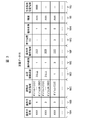
- FIG. 3 shows a specific configuration example of the definition data 16.
- the definition data 16 is definition information on the configuration and operation method of each operator on the control panel displayed on the display 4 and is created in advance by the user.
- the definition data 16 includes an operator name column 16A, an operator type column 16B, a contact point detection area column 16C, a required number of contact points column 16D, an operation type column 16E, an operator operation area column 16F, It has a table configuration including a pressing time column 16G, a holding presence / absence column 16H, a threshold value column 16I, and a pull-holdable area column 16J. In this table, one row corresponds to one operator on the control panel displayed on the display 4.
- the name of the corresponding operator displayed on the display 4 is stored in the operator name column 16A, and the type of the operator is stored in the operator type column 16B.
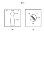
- a "push button” which is an operation element of a pressing type
- a "handle switch” which is an operation element of a type which grips and rotates the handle portion 40A as shown in FIG.
- a "knob-type button” which is a type of operation element for pinching and rotating the knob 41A as shown in FIG. 4B.
- the contact point detection area column 16C stores, for the corresponding operator, definition information (for example, a mathematical expression) of the contact point detection area 42 having a range as shown in FIG. 5A.
- the contact point detection area 42 is an area on the CG image where the touch operation by the driving trainee on the image display surface of the display 4 is effective.
- an inequality for example, x 2 / a 2 representing the inside of the ellipse is used. + Y 2 / b 2 ⁇ 1) defines the contact point detection area 42, and this inequality is stored in the corresponding contact point detection area column 16C as definition information of the contact point detection area 42.
- the contact point detection area 42 has a circular shape
- the contact point detection area 42 is defined by an inequality (for example, x 2 + y 2 ⁇ c 2 ) representing the inside of the circle.
- the definition information of the point detection area 42 is stored in the corresponding contact point detection area column 16C.
- the contact point detection area 42 may be defined by area coordinates. In this case, the area coordinates are stored in the corresponding contact point detection area column 16C.
- the contact point detection area 42 is set on or around the operator that is considered to be in contact with the operator's finger when operating the actual operator.
- a contact point detection area 42 is provided on the upper surface of the operator in a CG image displayed on the display 4 (a CG image of a control panel of a nuclear power plant; the same applies hereinafter). Is set.
- a knob-type button for example, a circular contact point detection area 42 is set so as to protrude evenly on both sides of the knob 41A (FIG. 4B) of the operator in the CG image.
- an elliptical contact point detection area 42 is set so as to protrude evenly on both sides of the handle 40A of the operator in the CG image. Is done.
- the type of the operation element is a knob-type button or a handle-type switch
- the position and the inclination of the contact point detection area 42 change according to the rotation angle of the operation element.
- the definition information of the contact point detection area 42 is generated, and the definition information is stored in the corresponding contact point detection area column 16C.
- the required contact point column 16D stores the number of contact points required to operate the corresponding operator in the CG image displayed on the display 4 (hereinafter, referred to as the required number of contact points).
- the required number of contact points is the number of fingers of the driving trainee who should touch the image display surface of the display 4 in the contact point detection area 42 set for the operator when operating the operator.
- the required number of contact points is set to the same number as the number of fingers required when operating the actual operator. For example, if the operation element is a push button, one point is set. If the operation element is a knob-type button or a handle-type switch, two or more values or ranges are set as the required number of contact points of the operation element.
- the operation type column 16E stores a number indicating the type of operation when operating the corresponding operator in the CG image displayed on the display 4.
- two types of operations “slide” and “press”, are defined.
- “slide” “1” is stored in the operation type column 16E, and in the case of “press”, the operation type is “2” is stored in the column 16E.
- “slide” also includes a rotation operation.
- the operation element operation area column 16F stores definition information of the operation element operation area 43 (FIG. 5B) preset for the corresponding operation element.
- the “operator operation area” means that the driving trainee should slide the finger while keeping the finger in contact with the image display surface of the display 4 in order to operate the corresponding operator in the CG image displayed on the display 4. Refers to the area on the CG image.
- the operating element operation area 43 is used when an operating part such as the handle 40A or the knob 41A is rotated (displaced) within its movable range. It is defined based on the movement trajectory of the contact point detection area 42 of the operator. For example, in the case of the handle-type switch shown in FIG. 5A, an arc-shaped area shown in FIG.
- a mathematical expression representing the operator operation area 43 of the corresponding operator is stored as definition information of the operator operation area 43.
- This formula is automatically calculated by the state determination / control unit 35 (FIG. 2) based on the formula representing the contact point detection area 42 defined by the user, and is stored in the operation element operation area column 16F.
- the movement locus of the contact point detection area 42 of the operating element when the operating part of the operating element is rotated (displaced) within the movable range is simply used as the operating element operation area 43.
- the user can set additional conditions such as a boundary condition of the movement locus with respect to the range of the operation element operation area 43.
- the additional conditions set at this time are stored in the corresponding operator operation area column 16F.
- the additional condition for setting only a part of the movement trajectory of the contact point detection area 42 of the operator as the operator operation area 43 can be set, so that the operation training of the operator under more severe conditions can be performed. Can be performed.
- the pressing time column 16G when the corresponding operation element is a push button, the time to keep pressing the touch button (touching the operation element) in order to operate the push button is stored.
- a large number of pushbuttons are provided on a control panel of a nuclear power plant, and some of these pushbuttons not only respond immediately upon being pressed but also require a long press. Therefore, when the corresponding operator is a push button, the press time of the push button required to execute the function or operation associated with the push button is stored in the press time field 16G.
- a flag (hereinafter, referred to as a holding presence / absence flag) indicating whether or not the corresponding operator is a pull-hold type is stored.
- the “pull-holding type” operation device is an operation device that requires an operation of pulling the operation device itself forward to continue the ON state or the OFF state when the ON operation or the OFF operation is performed.
- the holding presence / absence flag is set to “1” when the corresponding operator is of the pull-hold type, and is set to “0” when the corresponding operator is not of the pull-hold type.
- the threshold value column 16I stores a threshold value set by the user in advance for the corresponding operation element
- the pull-holdable area field 16J stores position information of the pull-holdable area set in advance by the user for the corresponding operation element. Is stored. Details of the “threshold” and the “pullable area” will be described later.
- the operating element is a handle switch 40 as shown in FIG.
- the handle-type switch 40 shown in FIG. 6A is a graphic image created by a user using a dedicated tool.
- the ellipse indicates the contact point detection area 42 defined for the handle switch 40 in the definition data 16, and the point 44 indicates the touch position of the finger of the driving trainee on the display 4.
- these contact point detection areas 42 and points 44 are not displayed in the actual CG image.
- the driving trainee places the necessary number of contact points defined by the definition data 16 on the contact point detection area 42 of the graphic image of the handle switch 40 in the initial state. Touch your finger.
- the required number of contact points of the handle switch 40 is set to “2 or more”, so that the driving trainee can use, for example, two or more thumbs and index fingers.
- the finger is touched on the contact point detection area 42.
- the state of the handle switch 40 is changed from the inoperable state to the operable state. (Hereinafter, referred to as a selected state).
- the driving trainee maintains the state of touching two or more points on the contact point detection area 42 of the handle-type switch 40 as described above.
- the finger is slid on the image display surface of the display 4 in the ON or OFF direction of the handle-type switch 40 so as to draw an arc around the rotation center of the unit 40A.
- the handle switch 40 is displayed so as to move (rotate) in synchronization with the movement of the finger of the driving trainee.
- the finger of the driving trainee deviated from the operator operation region 43 of the handle switch 40, and the number of fingers of the driving trainer touching the operator operation region 43 was defined for the handle switch 40.
- the number of required contact points is less than the required number of contact points, even if the driving trainee moves his / her finger in the ON or OFF direction of the handle switch 40, the operation of the driving trainee at that time becomes invalid, and the handle unit 40A is turned off. Does not rotate in synchronization with the movement of the driver's finger.
- whether or not the operator has been correctly operated by the driver is determined by the operator's fingers in the selected state and the operator's fingers for the required number of contact points defined for the operator. It is determined based on whether or not the user has slid within the operating element operation area 43.
- the driving trainee then moves the handle portion 40A of the handle switch 40 to a preset ON position or OFF position (for example, a contact inspection defined by the definition data 16).
- a preset ON position or OFF position for example, a contact inspection defined by the definition data 16.
- the handle 40A of the handle-type switch 40 When the handle-type switch 40 has a holding function, after the handle 40A of the handle-type switch 40 reaches the ON position or the OFF position, the handle 40A of the handle-type switch 40 is moved to the ON position or the OFF position. It is displayed in the state where it stopped at the off position.
- the handle portion 40A of the expression switch 40 is displayed in a state where it is returned to the original initial position (home position).
- the operation element is of the pull-hold type
- the operation state of the operation state is “pulled ( Operation).
- this “pulling” operation is expressed by sliding a finger downward on the image display surface of the display 4.
- FIG. 7A shows the pull-hold type handle switch 40 displayed on the display 4.
- the holding presence / absence flag indicating whether or not the corresponding operator is a pull holding type is stored in the holding presence / absence column 16H (FIG. 3) of the definition data 16,
- the state determination / control unit 35 (FIG. 2) can easily determine whether or not the operation element is a pull-hold type by the holding presence / absence flag.
- this area in the CG image as shown in FIG. Is referred to as a pull-holding area.
- the finger is slid downward in the state of being kept in contact with the image display surface of the display 4 within the area 45.
- the pull-holdable area 45 is set in advance by the user using area coordinates or mathematical formulas, and its definition information is stored and managed in the pull-holdable area column 16J of the definition data 16 (FIG. 3).
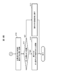
- FIGS. 8A and 8B are a series of processes executed in the driving training simulation system 1 in relation to the operation of the operator as described above. The flow of is shown. This processing is started when the driving trainee touches the display 4, and first, touch information is transmitted from the display 4 (FIGS. 1 and 2) to the monitoring / operation terminal 3 (FIGS. 1 and 2) (S1). ), And the touch information is transferred from the monitoring / operation terminal 3 to the state determination / control unit 35 (FIG. 2) of the control server 2 (FIGS. 1 and 2) (S2).
- the state determination / control unit 35 Upon receiving the touch information, the state determination / control unit 35 compares the touch information with the definition data 16 (FIG. 2) (S3), and performs a touch operation performed at that time recognized based on the touch information. It is determined whether or not it is valid (S4). Specifically, the state determination / control unit 35 determines that the position on the CG image touched by the driving trainee at that time, which is recognized based on the touch information, is the contact point detection area 42 of any of the operators (FIG. 5). Then, it is determined whether or not the operator satisfies the condition of the required number of contact points defined by the definition data 16 at that time (whether or not the fingers of the required number of contacts have been touched).
- the state determination / control unit 35 finally determines the driving trainee from the image display surface of the display 4 based on the touch information given from the display 4 via the monitoring / operation terminal 3. It is determined whether or not the finger has been released (S5).
- step S10 If a positive result is obtained in this determination, the process proceeds to step S10. On the other hand, if a negative result is obtained in the determination of step S5, the process returns to step S1, and thereafter, the processes of steps S1 to S5 are repeated until a positive result is obtained in step S4 or step S5. The same is repeated.
- step S4 determines whether or not the finger of the driving trainee has been released from the display 4 as in step S5 (S6). . Then, if a positive result is obtained in this determination, the process proceeds to step S10.
- step S6 determines that the operator whose touch is determined to be valid in step S4 (hereinafter, this is referred to as the target operator) ) Is determined to be in a selected state where operation is possible (S7).
- step S7 If the state determination and control unit 35 obtains a negative result in this determination, it switches the state of the target operator from the inoperable state to the operable selected state (S8). Thus, the target operator is thereafter operable by the driving trainee. Thereafter, the process returns to step S1, and the processes after step S1 are executed in the same manner as described above. In the second and subsequent loops, a positive result is obtained in step S7.
- the state determination / control unit 35 reads the CG data 15 (FIG. 2) from the database 17 (FIG. 1), and then reads the CG data 15 from the display 4 at that time.
- the control unit generates image data of the control panel as if the target operator moved or rotated to the position and state based on the touch information given via the terminal 3 (S9), and transmits this to the monitoring / operation terminal 3. Thereby, a CG image of the control panel in such a state is displayed on the display 4 based on the image data.
- step S5 or step S6 the state determination / control unit 35 determines the state of the target operator. To the original inoperable state (S10).
- the state determination / control unit 35 determines whether the position of the operation part such as the handle part or the knob part of the target operation element is at the ON position or the OFF position (S11), and a positive result is obtained. If the target operation element has been turned on or off (S12), the series of processing is terminated. Therefore, in this case, the state of the meter or the like of the control panel displayed on the display 4 can be switched as necessary to the state when the target operation element is turned on or off.
- step S11 when a negative result is obtained in the determination of step S11, the state determination and control unit 35 returns the state of the target operator to the initial state (the state of being at the home position) (S13). Thereafter, this series of processing ends. Therefore, in this case, the state of the meter and the like of the control panel displayed on the display 4 is also returned to the state before the operation of the target operator is started.
- Some operation training simulators for nuclear power plants use a liquid crystal display with a life-size screen size, such as a class-top simulator.
- the driving trainer touches the contact point detection area 42 of the target operator to be operated. Even if it is intended, the touched position is actually slightly deviated from the contact point detection area 42, and there is a case where the operator cannot be operated.
- the user can extend the contact point detection area 42 of the operator by updating the definition data 16, but generates definition information of the extended contact point detection area 42 and transmits the definition information to the control server 2. Work such as registration is required. Therefore, the driving training simulation system 1 is equipped with a contact point detection area automatic correction function for automatically correcting the contact point detection area 42 of the operator using statistical information without such a work. ing.
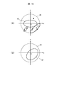
- the automatic correction of the contact point detection area based on the contact point detection area automatic correction function is performed using the threshold stored in the corresponding threshold column 16I (FIG. 3) of the definition data 16 described above with reference to FIG.
- the threshold value is set to an extended area (FIG. 9 (B)) surrounding the contact point detection area 42 defined as shown in FIG. 9 (A).
- mistouch is regarded as a mistouch, and as shown in FIG. (The coordinates of each black point in the mistouch detection area 47 in FIG. 10A) are stored in the monitoring / operation terminal 3 (FIGS. 1 and 2) as mistouch information.
- the mistouch information is periodically transmitted to the state determination / control unit 35 (FIG. 1) of the control server 2 (FIGS. 1 and 2), and the state determination / control unit 35 performs an operation based on the mistouch information.
- FIG. 10B a new contact point detection area 42 'extended and corrected by the statistical analysis processing is redefined for each child.
- the monitoring / operation terminal 3 is provided with a data aggregation processing unit 34 (FIG. 2).
- the data aggregation processing unit 34 is a functional unit embodied by the CPU 20 (FIG. 1) executing the client-side simulation program 23 (FIG. 1) stored in the memory 21 (FIG. 1) of the monitoring / operation terminal 3. is there.
- the threshold value for each operator defined by the definition data 16 is given to the data totaling processing unit 34 from the state determination / control unit 35 (FIG. 2) of the control server 2 in advance.
- the data totaling processing unit 34 performs the corresponding operation performed by the driving trainee at that time based on the touch information. It is determined whether or not the touch to is a mistouch. If the data summation processing unit 34 determines that the touch is a mistouch, the monitoring / operation terminal uses the position (coordinates) on the CG image touched by the driving trainee as mistouch information for the operator at that time. 3 is stored in the storage device. Then, the data aggregation processing unit 34 periodically transmits the mistouch information for each operation element accumulated in this manner to the state determination / control unit 35 of the control server 2.
- the state determination / control unit 35 When the state determination / control unit 35 receives the mistouch information for each operation element transmitted from the data tabulation processing unit 34, the state determination / control unit 35 analyzes the corresponding mistouch information for each operation element, and defines the operation element.
- the region optimization calculation of the contact point detection region 42 (FIGS. 9 and 10) is executed.
- “Region optimization calculation” is a calculation for formulating a continuous or discrete region by formulating a region by a shape optimization problem, which is one of the optimization techniques.
- the state determination / control unit 35 defines the definition information (FIG. 10B) of the new contact point detection area 42 ′ (FIG. 10B) that has been extended and corrected for each extended operator obtained by such area optimization calculation.
- the contact point detection area 42 of each operator is redefined by overwriting the corresponding contact point detection area column 16C of the definition data 16 (FIG. 3).
- the state determination / control unit 35 determines whether or not the operating element in which the definition information of the plurality of contact point detection areas 42 is stored in the contact point detection area column 16C, such as a handle switch or a knob switch.
- the definition information of the contact point detection area 42 after the extended correction is also calculated, and these calculation results are overwritten on the definition information of the corresponding contact point detection area 42 stored in the corresponding contact point detection area column 16C.
- the state determination / control unit 35 updates the definition information of all the contact point detection areas stored in each contact point detection area column 16C to the definition information after the extended correction.
- the state determination and control unit 35 transmits the definition information of the contact point detection area 42 for each operator updated in this manner to the data totaling unit 34 of the monitoring / operation terminal 3.
- the data totaling processing unit 34 thereafter detects a mistouch for each operator using the definition information of the new contact point detection area 42.
- the state determination / control unit 35 for each operator, based on the definition information of the updated contact point detection area 42 ', a new operator operation area 43 (corresponding to the updated contact point detection area 42'.
- the definition information of FIG. 5 is calculated, and the definition information of the operation element operation area 43 of the operation element stored in the corresponding operation element operation field 16F of the definition data 16 is calculated as described above.
- the operation information is updated to the definition information of the operation element operation area 43.
- FIG. 11 shows a series of processing (hereinafter, referred to as “the following) that is periodically executed in the driving training simulation system 1 in relation to the above-described contact point detection area automatic correction function. This is called a contact point detection area automatic correction process).
- This contact point detection area automatic correction processing is started when the driving training simulation system 1 operates, and first, the data aggregation processing unit 34 of the monitoring / operation terminal 3 is transmitted from the touch information transmission unit 31 of the display 4. Based on the touch information, mistouch information for each operation element is generated and stored (S20).
- the data tabulation processing unit 34 determines whether or not a predetermined time has elapsed since the last time the accumulated mistouch information for each operation element was transmitted to the state determination / control unit 35 of the control server 2 (S21). If a negative result is obtained in this determination, the data tabulation processing unit 34 returns to step S20, and continues accumulating the mistouch information for each operation element.
- the data aggregation processing unit 34 obtains a positive result in step S21.
- the mistouch information for each operation element accumulated from the previous time to this time is transmitted to the state determination / control unit 35 of the control server 2 (S22).
- the state determination / control unit 35 of the control server 2 performs an area optimization algorithm using the corresponding mistouch information for each operator.
- the definition information of the new contact point detection area 42 '(FIG. 10B) is calculated.
- the state determination / control unit 35 defines a new operation element operation area 43 (FIG. 5B) for each operation element based on the calculated definition information of the new contact point detection area 42 'for each operation element. Information is calculated (S23).
- the state determination / control unit 35 stores the definition information of the new contact point detection area 42 'for each operation element calculated in step S23 in the corresponding contact point detection area column 16C of the definition data 16 (FIG. 3).
- the definition information of the new operation element operation area 43 for each operation element calculated in step S23 is stored in the corresponding operation element operation area column 16F (FIG. 3) of the definition data 16 (S24).
- the state determination / control unit 35 transmits the definition information of the new contact point detection area 42 'for each operation element calculated in step S23 to the data aggregation processing unit 34 of the monitoring / operation terminal 3 (S25). Then, after that, the processing from step S20 is repeated.
- the data tabulation processing unit 34 uses the definition information of the new contact point detection area 42 'for each operator given from the state determination / control unit 35 in the immediately preceding step S25. Mistouch information for each operator is generated and stored. In this way, in the driving training simulation system 1, the contact point detection area 42 of each operator is extended and corrected as appropriate.
- the contact point detection area 42 of the operator is automatically extended and corrected by the statistical analysis processing, a complicated operation such as creation and update of the definition data 16 by the user is performed. Without necessity, it is possible to suppress the occurrence of a mistouch caused by a parallax error, a height, and the like of the driving trainee. Therefore, according to the present embodiment, a highly convenient driving training simulation system can be provided.
- control server 2 and the monitoring / operation terminal 3 are configured as separate bodies.
- the present invention is not limited to this.
- the function mounted on the server 2 and the function mounted on the monitoring / operation terminal 3 may be mounted on one computer device.
- the operator operation area 43 is set separately from the contact point detection area 42 that moves or rotates in conjunction with the operation part.
- the present invention is not limited to this, and the operation element operation area 43 may not be set.
- the operator operation area 43 it is possible to perform more difficult training.
- the present invention can be widely applied to various simulation systems in addition to a simulation system for operation training of a nuclear power plant.
Landscapes
- Engineering & Computer Science (AREA)
- Business, Economics & Management (AREA)
- Theoretical Computer Science (AREA)
- Physics & Mathematics (AREA)
- General Physics & Mathematics (AREA)
- Educational Administration (AREA)
- Educational Technology (AREA)
- Tourism & Hospitality (AREA)
- General Engineering & Computer Science (AREA)
- Health & Medical Sciences (AREA)
- Primary Health Care (AREA)
- Strategic Management (AREA)
- Marketing (AREA)
- General Business, Economics & Management (AREA)
- Human Resources & Organizations (AREA)
- General Health & Medical Sciences (AREA)
- Economics (AREA)
- Human Computer Interaction (AREA)
- User Interface Of Digital Computer (AREA)
- Management, Administration, Business Operations System, And Electronic Commerce (AREA)
- Rehabilitation Tools (AREA)
Abstract
L'invention concerne un système de simulation comprenant : un dispositif d'affichage d'opération tactile ; un dispositif d'enregistrement qui contient des données de définition qui définissent un procédé d'opération d'un opérateur qui est affiché sur l'affichage ; et une unité de commande qui affiche, sur un écran tactile, une image graphique de l'opérateur, qui simule un mouvement réel de l'opérateur, les données de définition comprenant des informations de définition concernant une première zone définie sur l'image graphique de l'opérateur ou une partie périphérique de l'image graphique, et le nombre de points de contact requis, qui est le nombre de doigts requis pour faire fonctionner l'opérateur sur le dispositif d'affichage. Le nombre de points de contact requis est réglé sur le nombre de doigts réellement nécessaires, et lorsque le nombre de doigts en contact avec la première zone de l'opérateur affiché sur l'affichage satisfait une condition pour le nombre de points de contact requis de l'opérateur, qui est défini dans les données de définition, l'unité de commande amène un état de l'opérateur à être commuté dans un état de sélection actionnable.
Applications Claiming Priority (2)
| Application Number | Priority Date | Filing Date | Title |
|---|---|---|---|
| JP2018121024A JP6850768B2 (ja) | 2018-06-26 | 2018-06-26 | シミュレーションシステム及びその制御方法 |
| JP2018-121024 | 2018-06-26 |
Publications (1)
| Publication Number | Publication Date |
|---|---|
| WO2020003645A1 true WO2020003645A1 (fr) | 2020-01-02 |
Family
ID=68986935
Family Applications (1)
| Application Number | Title | Priority Date | Filing Date |
|---|---|---|---|
| PCT/JP2019/011020 Ceased WO2020003645A1 (fr) | 2018-06-26 | 2019-03-15 | Système de simulation et son procédé de commande |
Country Status (2)
| Country | Link |
|---|---|
| JP (1) | JP6850768B2 (fr) |
| WO (1) | WO2020003645A1 (fr) |
Cited By (1)
| Publication number | Priority date | Publication date | Assignee | Title |
|---|---|---|---|---|
| WO2023016193A1 (fr) * | 2021-08-10 | 2023-02-16 | Oppo广东移动通信有限公司 | Procédé de commande d'appareil, dispositif, appareil électronique et support de stockage |
Citations (6)
| Publication number | Priority date | Publication date | Assignee | Title |
|---|---|---|---|---|
| JPH0736359A (ja) * | 1993-07-16 | 1995-02-07 | Hitachi Ltd | プラントシミュレータ装置及びプラントシミュレーション画面表示法 |
| JP2004118383A (ja) * | 2002-09-25 | 2004-04-15 | Kawasaki Heavy Ind Ltd | 仮想スイッチ類提供方法および装置 |
| JP2014186699A (ja) * | 2013-03-25 | 2014-10-02 | Asuko:Kk | 入力装置、入力装置の制御方法、制御プログラムおよび記録媒体 |
| WO2017073013A1 (fr) * | 2015-10-26 | 2017-05-04 | ソニー株式会社 | Dispositif de saisie d'opération, dispositif de traitement d'informations, procédé de traitement d'informations et programme |
| US9703476B1 (en) * | 2010-12-23 | 2017-07-11 | The Boeing Company | Multi-touch cockpit interface for controlling aircraft systems |
| WO2017164107A1 (fr) * | 2016-03-25 | 2017-09-28 | ヤマハ株式会社 | Dispositif et procédé pour établir un paramètre |
-
2018
- 2018-06-26 JP JP2018121024A patent/JP6850768B2/ja active Active
-
2019
- 2019-03-15 WO PCT/JP2019/011020 patent/WO2020003645A1/fr not_active Ceased
Patent Citations (6)
| Publication number | Priority date | Publication date | Assignee | Title |
|---|---|---|---|---|
| JPH0736359A (ja) * | 1993-07-16 | 1995-02-07 | Hitachi Ltd | プラントシミュレータ装置及びプラントシミュレーション画面表示法 |
| JP2004118383A (ja) * | 2002-09-25 | 2004-04-15 | Kawasaki Heavy Ind Ltd | 仮想スイッチ類提供方法および装置 |
| US9703476B1 (en) * | 2010-12-23 | 2017-07-11 | The Boeing Company | Multi-touch cockpit interface for controlling aircraft systems |
| JP2014186699A (ja) * | 2013-03-25 | 2014-10-02 | Asuko:Kk | 入力装置、入力装置の制御方法、制御プログラムおよび記録媒体 |
| WO2017073013A1 (fr) * | 2015-10-26 | 2017-05-04 | ソニー株式会社 | Dispositif de saisie d'opération, dispositif de traitement d'informations, procédé de traitement d'informations et programme |
| WO2017164107A1 (fr) * | 2016-03-25 | 2017-09-28 | ヤマハ株式会社 | Dispositif et procédé pour établir un paramètre |
Cited By (1)
| Publication number | Priority date | Publication date | Assignee | Title |
|---|---|---|---|---|
| WO2023016193A1 (fr) * | 2021-08-10 | 2023-02-16 | Oppo广东移动通信有限公司 | Procédé de commande d'appareil, dispositif, appareil électronique et support de stockage |
Also Published As
| Publication number | Publication date |
|---|---|
| JP2020003565A (ja) | 2020-01-09 |
| JP6850768B2 (ja) | 2021-03-31 |
Similar Documents
| Publication | Publication Date | Title |
|---|---|---|
| AU2013200707B2 (en) | Adjustment mechanisms for virtual knobs on a touchscreen interface | |
| US8205165B2 (en) | Apparatus to create, save and format text documents using gaze control and method associated based on the optimized positioning of cursor | |
| US20020130834A1 (en) | System and method for universal control of devices | |
| WO2014058946A1 (fr) | Dispositif tactile configurable multifonction | |
| CN113680064B (zh) | 游戏中虚拟角色控制方法、装置、设备及存储介质 | |
| CN107132988A (zh) | 虚拟对象状态控制方法、装置、电子设备及存储介质 | |
| US8172681B2 (en) | Storage medium having stored therein game program and game device | |
| US9146667B2 (en) | Electronic device, display system, and method of displaying a display screen of the electronic device | |
| CN105630341A (zh) | 触控显示装置、触控显示方法及无人机 | |
| NO310748B1 (no) | Metode og utstyr for forbedret kommunikasjon mellom menneske og datamaskin | |
| EP2329342A2 (fr) | Appareil de commande haptique intégré et afficheur tactile sensitif | |
| US20190007229A1 (en) | Device and method for controlling electrical appliances | |
| CN103870061A (zh) | 在多点触控设备上实现鼠标功能的方法 | |
| WO2020003645A1 (fr) | Système de simulation et son procédé de commande | |
| CN104317485B (zh) | 电子黑板显示控制方法和装置 | |
| JP7839687B2 (ja) | フライトシミュレーションシステム | |
| JP2004118383A (ja) | 仮想スイッチ類提供方法および装置 | |
| JPH01177609A (ja) | Pcのシュミレーション方式 | |
| JP5524153B2 (ja) | タッチ操作式ソフトウェアキーボードの表示システム、表示方法及びプログラム | |
| JP4735549B2 (ja) | 電子機器および電子機器制御プログラム | |
| Saunier et al. | Controller evaluation for earthwork teleoperation and training in virtual reality | |
| JP2001075471A (ja) | キーボード練習装置 | |
| JPH06289773A (ja) | 発電所運転訓練装置 | |
| JPH0922330A (ja) | タッチパネルの入力方法 | |
| US20220366803A1 (en) | Computer-implemented methods and systems for designing and conducting virtual reality experiments |
Legal Events
| Date | Code | Title | Description |
|---|---|---|---|
| 121 | Ep: the epo has been informed by wipo that ep was designated in this application |
Ref document number: 19826795 Country of ref document: EP Kind code of ref document: A1 |
|
| NENP | Non-entry into the national phase |
Ref country code: DE |
|
| 122 | Ep: pct application non-entry in european phase |
Ref document number: 19826795 Country of ref document: EP Kind code of ref document: A1 |