WO2020003645A1 - シミュレーションシステム及びその制御方法 - Google Patents
シミュレーションシステム及びその制御方法 Download PDFInfo
- Publication number
- WO2020003645A1 WO2020003645A1 PCT/JP2019/011020 JP2019011020W WO2020003645A1 WO 2020003645 A1 WO2020003645 A1 WO 2020003645A1 JP 2019011020 W JP2019011020 W JP 2019011020W WO 2020003645 A1 WO2020003645 A1 WO 2020003645A1
- Authority
- WO
- WIPO (PCT)
- Prior art keywords
- operator
- display
- area
- control unit
- simulation system
- Prior art date
- Legal status (The legal status is an assumption and is not a legal conclusion. Google has not performed a legal analysis and makes no representation as to the accuracy of the status listed.)
- Ceased
Links
Images


Classifications
-
- G—PHYSICS
- G06—COMPUTING OR CALCULATING; COUNTING
- G06F—ELECTRIC DIGITAL DATA PROCESSING
- G06F3/00—Input arrangements for transferring data to be processed into a form capable of being handled by the computer; Output arrangements for transferring data from processing unit to output unit, e.g. interface arrangements
- G06F3/01—Input arrangements or combined input and output arrangements for interaction between user and computer
- G06F3/048—Interaction techniques based on graphical user interfaces [GUI]
- G06F3/0487—Interaction techniques based on graphical user interfaces [GUI] using specific features provided by the input device, e.g. functions controlled by the rotation of a mouse with dual sensing arrangements, or of the nature of the input device, e.g. tap gestures based on pressure sensed by a digitiser
- G06F3/0488—Interaction techniques based on graphical user interfaces [GUI] using specific features provided by the input device, e.g. functions controlled by the rotation of a mouse with dual sensing arrangements, or of the nature of the input device, e.g. tap gestures based on pressure sensed by a digitiser using a touch-screen or digitiser, e.g. input of commands through traced gestures
-
- G—PHYSICS
- G06—COMPUTING OR CALCULATING; COUNTING
- G06Q—INFORMATION AND COMMUNICATION TECHNOLOGY [ICT] SPECIALLY ADAPTED FOR ADMINISTRATIVE, COMMERCIAL, FINANCIAL, MANAGERIAL OR SUPERVISORY PURPOSES; SYSTEMS OR METHODS SPECIALLY ADAPTED FOR ADMINISTRATIVE, COMMERCIAL, FINANCIAL, MANAGERIAL OR SUPERVISORY PURPOSES, NOT OTHERWISE PROVIDED FOR
- G06Q50/00—Information and communication technology [ICT] specially adapted for implementation of business processes of specific business sectors, e.g. utilities or tourism
- G06Q50/10—Services
- G06Q50/20—Education
-
- G—PHYSICS
- G09—EDUCATION; CRYPTOGRAPHY; DISPLAY; ADVERTISING; SEALS
- G09B—EDUCATIONAL OR DEMONSTRATION APPLIANCES; APPLIANCES FOR TEACHING, OR COMMUNICATING WITH, THE BLIND, DEAF OR MUTE; MODELS; PLANETARIA; GLOBES; MAPS; DIAGRAMS
- G09B9/00—Simulators for teaching or training purposes
Definitions
- the present invention relates to a simulation system and a control method thereof, and is suitably applied to, for example, an operation training simulation system for a nuclear power plant.
- the operation control of a nuclear power plant is performed by an operator monitoring and operating a central operation monitoring panel and an operation monitoring auxiliary panel (hereinafter collectively referred to as a control panel) installed in a central control room.
- a control panel an operation monitoring auxiliary panel installed in a central control room.
- Monitoring and operating such a nuclear power plant requires in-depth knowledge and skills, and training in monitoring and operating skills is indispensable.
- This type of simulator faithfully reproduces the control panel in the central control room of a nuclear power plant with hardware, so that a trainee (hereinafter referred to as an operation trainer) uses this simulator. It can be used to perform monitoring and operation training with the same feeling as a real nuclear power plant.
- a simulator composed of hardware requires a space as large as the space for installing a control panel in an actual nuclear power plant, and furthermore, there is a problem that a reasonable cost is required to install the simulator. Was.
- a control panel of a nuclear power plant is virtually displayed on a liquid crystal display, and furthermore, a plurality of large liquid crystal displays or glass top panels called a glass top type simulator are arranged.
- a simulator that displays a graphic that faithfully draws a control panel of a nuclear power plant has been developed there.
- Patent Document 1 discloses a technique for simulating the movement of virtual switches on a touch panel.
- the liquid crystal display and the glass top panel (hereinafter collectively referred to as a display) are provided with various controls such as hard buttons of a monitoring / operation control panel, handle switches and key switches.
- various controls such as hard buttons of a monitoring / operation control panel, handle switches and key switches.
- Virtual display with the same configuration as the monitoring / operation control panel.
- a driving trainer is configured to operate an operator such as a control panel or a hardware button virtually displayed on a display by touching the operator with his / her finger.
- the driving trainer operates the operating device displayed on the display. By touching with, the operator can be set to a selected state or an operation state, and "push”, “grab”, “turn”, and / or "" necessary for operation of the actual operator installed in the nuclear power plant. There was no need for finger movements such as "pull”.
- the present invention has been made in view of the above points, and is intended to propose a simulation system and a control method thereof that can provide a more effective operation training environment for operators.
- a touch operation type display that detects a touch operation on an image display surface and outputs a detection result
- a storage device that holds definition data defining an operation method of the operation device displayed on an image display surface and image data of a graphic image of the operation device, and a movement of the actual operation device based on the image data.
- Definition information and the controls displayed on the display defined as the required number of contact points Including the number of fingers required to operate, the required number of contact points of the operator is set to the number of fingers required when actually operating the operator, the control unit, The number of the fingers in contact with the first region of the operator displayed on the display, which is recognized based on the output of the display, and the required number of contact points of the operator defined by the definition data
- the state of the operation element is switched to a operable selection state.
- the simulation system detects a touch operation on an image display surface, and outputs a detection result;
- a storage device that holds definition data defining an operation method of the operation device displayed on the image display surface of a display and image data of a graphic image of the operation device, and the actual operation device based on the image data
- the display information which is defined as the definition information of the area and the required number of contact points Including the number of fingers required to operate the displayed operator, the required number of contact points of the operator is set to the number of fingers required when operating the actual operator.
- the control unit recognizes based on the output of the display, the number of the fingers in contact with the first region of the operation element displayed on the display, and the number defined by the definition data.
- a second step for switching to is based on the output of the display, the number of the fingers in contact with the first region of the operation element displayed on the display, and the number defined by the definition data.
- a simulation system and a control method thereof that can provide a more effective operation training environment for operators can be realized.
- FIG. 2 is a block diagram illustrating a hardware configuration of a driving training simulation system according to the present embodiment.
- FIG. 2 is a block diagram illustrating a logical configuration of a driving training simulation system according to the present embodiment.
- 5 is a chart showing a configuration example of definition data.
- FIGS. 3A and 3B are diagrams for explaining types of operators.
- FIG. FIG. 7A is a diagram for explaining a contact point detection region
- FIG. 8B is a diagram for explaining an operation element operation region.
- (A)-(C) is a figure provided for explanation of the operation method of the operation element displayed on the display.
- (A) And (B) is a figure provided for description of the operation method of the pull-hold type operation element displayed on the display.
- reference numeral 1 denotes a driving training simulation system according to the present embodiment as a whole.
- the operation training simulation system 1 is a system for performing operation training of a nuclear power plant, more precisely, operation training of a control panel installed in a central control room of a nuclear power plant. It comprises a plurality of monitoring / operation terminals 3 and a display 4.
- the control server 2 is a general-purpose server device including a CPU (Central Processing Unit) 10, a memory 11, a storage device 12, and a communication device 13.
- the CPU 10 is a processor that controls the operation of the entire control server 2.
- the memory 11 is formed of, for example, a semiconductor memory, and is mainly used as a work memory of the CPU 10.
- the memory 11 stores a later-described simulation program (hereinafter, referred to as a server-side simulation program) 14 read from the storage device 12.
- the storage device 12 is composed of a large-capacity nonvolatile storage device such as a hard disk device or an SSD (Solid State Drive), and stores programs and data to be stored for a long period of time.
- the programs stored in the storage device 12 are read into the memory 11 when the control server 2 is activated or necessary, and various processes of the control server 2 as a whole are executed by the CPU 10 executing the programs.
- the storage device 12 also stores a database 17.
- the database 17 includes CG data 15 (FIG. 2) of a CG (Computer Graphics) image simulating a control panel of a central control room of a nuclear power plant to be displayed on the display 4, and buttons displayed on the control panel.
- Definition data 16 (FIG. 2), which will be described later, relating to each operation element such as a switch is stored.
- the communication device 13 includes, for example, an NIC (Network Interface Card) or the like, and is connected to the monitoring / operation terminal 3 via the network 5.
- the communication device 13 performs protocol control during communication with the monitoring / control terminal 3.
- the monitoring / operation terminal 3 is a communication terminal device that constitutes a client / server system together with the control server 2 and includes a general-purpose computer device including a CPU 20, a memory 21, a storage device (not shown), and a communication device 22. You.
- the CPU 20, the memory 21, the storage device, and the communication device 22 have the same functions and configurations as the corresponding components (the CPU 10, the memory 11, the storage device 12, or the communication device 13) of the control server 2, respectively. Detailed description is omitted.
- the memory 21 of the monitoring / operation terminal 3 stores a simulation program (hereinafter, referred to as a client-side simulation program) 23 read from a storage device (not shown) when the monitoring / operation terminal 3 is activated or necessary. Is done.
- the display 4 is configured by, for example, a touch operation type display such as a liquid crystal touch panel that detects a touch of a finger of a driving trainee on an image display surface (hereinafter, this is referred to as a touch or a touch operation) and outputs a detection result. You.
- the display 4 displays an image based on image data provided from the monitoring / operation terminal 3 as described later.
- FIG. 2 shows a logical configuration of the driving training simulation system 1.
- the display 4 includes a screen display unit 30 and a touch information transmission unit 31.
- the screen display unit 30 includes a display device portion such as a liquid crystal panel of the display 4.
- the touch information transmission unit 31 is configured by a sensor film or the like attached to an image display surface of a display device portion of the display 4.
- the touch information transmission unit 31 detects a touch position (coordinates) of the finger of the driving trainee on the image display surface of the display 4 and outputs the detection result to the monitoring / operation terminal 3 as touch information.
- the monitoring / operation terminal 3 includes a screen display processing unit 32, a touch information processing unit 33, and a data totaling processing unit 34.
- the screen display processing unit 32, the touch information processing unit 33, and the data totaling processing unit 34 all execute the client-side simulation program 23 stored in the memory 21 (FIG. 1) by the CPU 20 (FIG. 1) of the monitoring / operation terminal 3. It is a functional unit embodied by executing.
- the screen display processing unit 32 displays a CG image of the control panel installed in the central control room of the nuclear power plant on the screen display unit 30 of the display 4 based on the image data provided from the control server 2. Further, the touch information processing unit 33 transfers the touch information transmitted from the touch information transmission unit 31 of the display 4 to the control server 2. Details of the data totaling unit 34 will be described later.
- the control server 2 includes a state determination / control unit 35.
- the state determination / control unit 35 is a functional unit embodied by the CPU 10 (FIG. 1) of the control server 2 executing the server-side simulation program 14 (FIG. 1) stored in the memory 11 (FIG. 1). .
- the state determination / control unit 35 reads necessary CG data 15 from the storage device 12 (FIG. 1) when necessary, generates image data of a CG image of the entire control panel based on the read CG data 15, and generates the generated image data. Is transmitted to the monitoring / operation terminal 3.
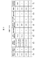
- FIG. 3 shows a specific configuration example of the definition data 16.
- the definition data 16 is definition information on the configuration and operation method of each operator on the control panel displayed on the display 4 and is created in advance by the user.
- the definition data 16 includes an operator name column 16A, an operator type column 16B, a contact point detection area column 16C, a required number of contact points column 16D, an operation type column 16E, an operator operation area column 16F, It has a table configuration including a pressing time column 16G, a holding presence / absence column 16H, a threshold value column 16I, and a pull-holdable area column 16J. In this table, one row corresponds to one operator on the control panel displayed on the display 4.
- the name of the corresponding operator displayed on the display 4 is stored in the operator name column 16A, and the type of the operator is stored in the operator type column 16B.
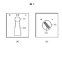
- a "push button” which is an operation element of a pressing type
- a "handle switch” which is an operation element of a type which grips and rotates the handle portion 40A as shown in FIG.
- a "knob-type button” which is a type of operation element for pinching and rotating the knob 41A as shown in FIG. 4B.
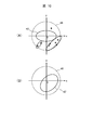
- the contact point detection area column 16C stores, for the corresponding operator, definition information (for example, a mathematical expression) of the contact point detection area 42 having a range as shown in FIG. 5A.
- the contact point detection area 42 is an area on the CG image where the touch operation by the driving trainee on the image display surface of the display 4 is effective.
- an inequality for example, x 2 / a 2 representing the inside of the ellipse is used. + Y 2 / b 2 ⁇ 1) defines the contact point detection area 42, and this inequality is stored in the corresponding contact point detection area column 16C as definition information of the contact point detection area 42.
- the contact point detection area 42 has a circular shape
- the contact point detection area 42 is defined by an inequality (for example, x 2 + y 2 ⁇ c 2 ) representing the inside of the circle.
- the definition information of the point detection area 42 is stored in the corresponding contact point detection area column 16C.
- the contact point detection area 42 may be defined by area coordinates. In this case, the area coordinates are stored in the corresponding contact point detection area column 16C.
- the contact point detection area 42 is set on or around the operator that is considered to be in contact with the operator's finger when operating the actual operator.
- a contact point detection area 42 is provided on the upper surface of the operator in a CG image displayed on the display 4 (a CG image of a control panel of a nuclear power plant; the same applies hereinafter). Is set.
- a knob-type button for example, a circular contact point detection area 42 is set so as to protrude evenly on both sides of the knob 41A (FIG. 4B) of the operator in the CG image.
- an elliptical contact point detection area 42 is set so as to protrude evenly on both sides of the handle 40A of the operator in the CG image. Is done.
- the type of the operation element is a knob-type button or a handle-type switch
- the position and the inclination of the contact point detection area 42 change according to the rotation angle of the operation element.
- the definition information of the contact point detection area 42 is generated, and the definition information is stored in the corresponding contact point detection area column 16C.
- the required contact point column 16D stores the number of contact points required to operate the corresponding operator in the CG image displayed on the display 4 (hereinafter, referred to as the required number of contact points).
- the required number of contact points is the number of fingers of the driving trainee who should touch the image display surface of the display 4 in the contact point detection area 42 set for the operator when operating the operator.
- the required number of contact points is set to the same number as the number of fingers required when operating the actual operator. For example, if the operation element is a push button, one point is set. If the operation element is a knob-type button or a handle-type switch, two or more values or ranges are set as the required number of contact points of the operation element.
- the operation type column 16E stores a number indicating the type of operation when operating the corresponding operator in the CG image displayed on the display 4.
- two types of operations “slide” and “press”, are defined.
- “slide” “1” is stored in the operation type column 16E, and in the case of “press”, the operation type is “2” is stored in the column 16E.
- “slide” also includes a rotation operation.
- the operation element operation area column 16F stores definition information of the operation element operation area 43 (FIG. 5B) preset for the corresponding operation element.
- the “operator operation area” means that the driving trainee should slide the finger while keeping the finger in contact with the image display surface of the display 4 in order to operate the corresponding operator in the CG image displayed on the display 4. Refers to the area on the CG image.
- the operating element operation area 43 is used when an operating part such as the handle 40A or the knob 41A is rotated (displaced) within its movable range. It is defined based on the movement trajectory of the contact point detection area 42 of the operator. For example, in the case of the handle-type switch shown in FIG. 5A, an arc-shaped area shown in FIG.
- a mathematical expression representing the operator operation area 43 of the corresponding operator is stored as definition information of the operator operation area 43.
- This formula is automatically calculated by the state determination / control unit 35 (FIG. 2) based on the formula representing the contact point detection area 42 defined by the user, and is stored in the operation element operation area column 16F.
- the movement locus of the contact point detection area 42 of the operating element when the operating part of the operating element is rotated (displaced) within the movable range is simply used as the operating element operation area 43.
- the user can set additional conditions such as a boundary condition of the movement locus with respect to the range of the operation element operation area 43.
- the additional conditions set at this time are stored in the corresponding operator operation area column 16F.
- the additional condition for setting only a part of the movement trajectory of the contact point detection area 42 of the operator as the operator operation area 43 can be set, so that the operation training of the operator under more severe conditions can be performed. Can be performed.
- the pressing time column 16G when the corresponding operation element is a push button, the time to keep pressing the touch button (touching the operation element) in order to operate the push button is stored.
- a large number of pushbuttons are provided on a control panel of a nuclear power plant, and some of these pushbuttons not only respond immediately upon being pressed but also require a long press. Therefore, when the corresponding operator is a push button, the press time of the push button required to execute the function or operation associated with the push button is stored in the press time field 16G.
- a flag (hereinafter, referred to as a holding presence / absence flag) indicating whether or not the corresponding operator is a pull-hold type is stored.
- the “pull-holding type” operation device is an operation device that requires an operation of pulling the operation device itself forward to continue the ON state or the OFF state when the ON operation or the OFF operation is performed.
- the holding presence / absence flag is set to “1” when the corresponding operator is of the pull-hold type, and is set to “0” when the corresponding operator is not of the pull-hold type.
- the threshold value column 16I stores a threshold value set by the user in advance for the corresponding operation element
- the pull-holdable area field 16J stores position information of the pull-holdable area set in advance by the user for the corresponding operation element. Is stored. Details of the “threshold” and the “pullable area” will be described later.
- the operating element is a handle switch 40 as shown in FIG.
- the handle-type switch 40 shown in FIG. 6A is a graphic image created by a user using a dedicated tool.
- the ellipse indicates the contact point detection area 42 defined for the handle switch 40 in the definition data 16, and the point 44 indicates the touch position of the finger of the driving trainee on the display 4.
- these contact point detection areas 42 and points 44 are not displayed in the actual CG image.
- the driving trainee places the necessary number of contact points defined by the definition data 16 on the contact point detection area 42 of the graphic image of the handle switch 40 in the initial state. Touch your finger.
- the required number of contact points of the handle switch 40 is set to “2 or more”, so that the driving trainee can use, for example, two or more thumbs and index fingers.
- the finger is touched on the contact point detection area 42.
- the state of the handle switch 40 is changed from the inoperable state to the operable state. (Hereinafter, referred to as a selected state).
- the driving trainee maintains the state of touching two or more points on the contact point detection area 42 of the handle-type switch 40 as described above.
- the finger is slid on the image display surface of the display 4 in the ON or OFF direction of the handle-type switch 40 so as to draw an arc around the rotation center of the unit 40A.
- the handle switch 40 is displayed so as to move (rotate) in synchronization with the movement of the finger of the driving trainee.
- the finger of the driving trainee deviated from the operator operation region 43 of the handle switch 40, and the number of fingers of the driving trainer touching the operator operation region 43 was defined for the handle switch 40.
- the number of required contact points is less than the required number of contact points, even if the driving trainee moves his / her finger in the ON or OFF direction of the handle switch 40, the operation of the driving trainee at that time becomes invalid, and the handle unit 40A is turned off. Does not rotate in synchronization with the movement of the driver's finger.
- whether or not the operator has been correctly operated by the driver is determined by the operator's fingers in the selected state and the operator's fingers for the required number of contact points defined for the operator. It is determined based on whether or not the user has slid within the operating element operation area 43.
- the driving trainee then moves the handle portion 40A of the handle switch 40 to a preset ON position or OFF position (for example, a contact inspection defined by the definition data 16).
- a preset ON position or OFF position for example, a contact inspection defined by the definition data 16.
- the handle 40A of the handle-type switch 40 When the handle-type switch 40 has a holding function, after the handle 40A of the handle-type switch 40 reaches the ON position or the OFF position, the handle 40A of the handle-type switch 40 is moved to the ON position or the OFF position. It is displayed in the state where it stopped at the off position.
- the handle portion 40A of the expression switch 40 is displayed in a state where it is returned to the original initial position (home position).
- the operation element is of the pull-hold type
- the operation state of the operation state is “pulled ( Operation).
- this “pulling” operation is expressed by sliding a finger downward on the image display surface of the display 4.
- FIG. 7A shows the pull-hold type handle switch 40 displayed on the display 4.
- the holding presence / absence flag indicating whether or not the corresponding operator is a pull holding type is stored in the holding presence / absence column 16H (FIG. 3) of the definition data 16,
- the state determination / control unit 35 (FIG. 2) can easily determine whether or not the operation element is a pull-hold type by the holding presence / absence flag.
- this area in the CG image as shown in FIG. Is referred to as a pull-holding area.
- the finger is slid downward in the state of being kept in contact with the image display surface of the display 4 within the area 45.
- the pull-holdable area 45 is set in advance by the user using area coordinates or mathematical formulas, and its definition information is stored and managed in the pull-holdable area column 16J of the definition data 16 (FIG. 3).
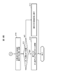
- FIGS. 8A and 8B are a series of processes executed in the driving training simulation system 1 in relation to the operation of the operator as described above. The flow of is shown. This processing is started when the driving trainee touches the display 4, and first, touch information is transmitted from the display 4 (FIGS. 1 and 2) to the monitoring / operation terminal 3 (FIGS. 1 and 2) (S1). ), And the touch information is transferred from the monitoring / operation terminal 3 to the state determination / control unit 35 (FIG. 2) of the control server 2 (FIGS. 1 and 2) (S2).
- the state determination / control unit 35 Upon receiving the touch information, the state determination / control unit 35 compares the touch information with the definition data 16 (FIG. 2) (S3), and performs a touch operation performed at that time recognized based on the touch information. It is determined whether or not it is valid (S4). Specifically, the state determination / control unit 35 determines that the position on the CG image touched by the driving trainee at that time, which is recognized based on the touch information, is the contact point detection area 42 of any of the operators (FIG. 5). Then, it is determined whether or not the operator satisfies the condition of the required number of contact points defined by the definition data 16 at that time (whether or not the fingers of the required number of contacts have been touched).
- the state determination / control unit 35 finally determines the driving trainee from the image display surface of the display 4 based on the touch information given from the display 4 via the monitoring / operation terminal 3. It is determined whether or not the finger has been released (S5).
- step S10 If a positive result is obtained in this determination, the process proceeds to step S10. On the other hand, if a negative result is obtained in the determination of step S5, the process returns to step S1, and thereafter, the processes of steps S1 to S5 are repeated until a positive result is obtained in step S4 or step S5. The same is repeated.
- step S4 determines whether or not the finger of the driving trainee has been released from the display 4 as in step S5 (S6). . Then, if a positive result is obtained in this determination, the process proceeds to step S10.
- step S6 determines that the operator whose touch is determined to be valid in step S4 (hereinafter, this is referred to as the target operator) ) Is determined to be in a selected state where operation is possible (S7).
- step S7 If the state determination and control unit 35 obtains a negative result in this determination, it switches the state of the target operator from the inoperable state to the operable selected state (S8). Thus, the target operator is thereafter operable by the driving trainee. Thereafter, the process returns to step S1, and the processes after step S1 are executed in the same manner as described above. In the second and subsequent loops, a positive result is obtained in step S7.
- the state determination / control unit 35 reads the CG data 15 (FIG. 2) from the database 17 (FIG. 1), and then reads the CG data 15 from the display 4 at that time.
- the control unit generates image data of the control panel as if the target operator moved or rotated to the position and state based on the touch information given via the terminal 3 (S9), and transmits this to the monitoring / operation terminal 3. Thereby, a CG image of the control panel in such a state is displayed on the display 4 based on the image data.
- step S5 or step S6 the state determination / control unit 35 determines the state of the target operator. To the original inoperable state (S10).
- the state determination / control unit 35 determines whether the position of the operation part such as the handle part or the knob part of the target operation element is at the ON position or the OFF position (S11), and a positive result is obtained. If the target operation element has been turned on or off (S12), the series of processing is terminated. Therefore, in this case, the state of the meter or the like of the control panel displayed on the display 4 can be switched as necessary to the state when the target operation element is turned on or off.
- step S11 when a negative result is obtained in the determination of step S11, the state determination and control unit 35 returns the state of the target operator to the initial state (the state of being at the home position) (S13). Thereafter, this series of processing ends. Therefore, in this case, the state of the meter and the like of the control panel displayed on the display 4 is also returned to the state before the operation of the target operator is started.
- Some operation training simulators for nuclear power plants use a liquid crystal display with a life-size screen size, such as a class-top simulator.
- the driving trainer touches the contact point detection area 42 of the target operator to be operated. Even if it is intended, the touched position is actually slightly deviated from the contact point detection area 42, and there is a case where the operator cannot be operated.
- the user can extend the contact point detection area 42 of the operator by updating the definition data 16, but generates definition information of the extended contact point detection area 42 and transmits the definition information to the control server 2. Work such as registration is required. Therefore, the driving training simulation system 1 is equipped with a contact point detection area automatic correction function for automatically correcting the contact point detection area 42 of the operator using statistical information without such a work. ing.
- the automatic correction of the contact point detection area based on the contact point detection area automatic correction function is performed using the threshold stored in the corresponding threshold column 16I (FIG. 3) of the definition data 16 described above with reference to FIG.
- the threshold value is set to an extended area (FIG. 9 (B)) surrounding the contact point detection area 42 defined as shown in FIG. 9 (A).
- mistouch is regarded as a mistouch, and as shown in FIG. (The coordinates of each black point in the mistouch detection area 47 in FIG. 10A) are stored in the monitoring / operation terminal 3 (FIGS. 1 and 2) as mistouch information.
- the mistouch information is periodically transmitted to the state determination / control unit 35 (FIG. 1) of the control server 2 (FIGS. 1 and 2), and the state determination / control unit 35 performs an operation based on the mistouch information.
- FIG. 10B a new contact point detection area 42 'extended and corrected by the statistical analysis processing is redefined for each child.
- the monitoring / operation terminal 3 is provided with a data aggregation processing unit 34 (FIG. 2).
- the data aggregation processing unit 34 is a functional unit embodied by the CPU 20 (FIG. 1) executing the client-side simulation program 23 (FIG. 1) stored in the memory 21 (FIG. 1) of the monitoring / operation terminal 3. is there.
- the threshold value for each operator defined by the definition data 16 is given to the data totaling processing unit 34 from the state determination / control unit 35 (FIG. 2) of the control server 2 in advance.
- the data totaling processing unit 34 performs the corresponding operation performed by the driving trainee at that time based on the touch information. It is determined whether or not the touch to is a mistouch. If the data summation processing unit 34 determines that the touch is a mistouch, the monitoring / operation terminal uses the position (coordinates) on the CG image touched by the driving trainee as mistouch information for the operator at that time. 3 is stored in the storage device. Then, the data aggregation processing unit 34 periodically transmits the mistouch information for each operation element accumulated in this manner to the state determination / control unit 35 of the control server 2.
- the state determination / control unit 35 When the state determination / control unit 35 receives the mistouch information for each operation element transmitted from the data tabulation processing unit 34, the state determination / control unit 35 analyzes the corresponding mistouch information for each operation element, and defines the operation element.
- the region optimization calculation of the contact point detection region 42 (FIGS. 9 and 10) is executed.
- “Region optimization calculation” is a calculation for formulating a continuous or discrete region by formulating a region by a shape optimization problem, which is one of the optimization techniques.
- the state determination / control unit 35 defines the definition information (FIG. 10B) of the new contact point detection area 42 ′ (FIG. 10B) that has been extended and corrected for each extended operator obtained by such area optimization calculation.
- the contact point detection area 42 of each operator is redefined by overwriting the corresponding contact point detection area column 16C of the definition data 16 (FIG. 3).
- the state determination / control unit 35 determines whether or not the operating element in which the definition information of the plurality of contact point detection areas 42 is stored in the contact point detection area column 16C, such as a handle switch or a knob switch.
- the definition information of the contact point detection area 42 after the extended correction is also calculated, and these calculation results are overwritten on the definition information of the corresponding contact point detection area 42 stored in the corresponding contact point detection area column 16C.
- the state determination / control unit 35 updates the definition information of all the contact point detection areas stored in each contact point detection area column 16C to the definition information after the extended correction.
- the state determination and control unit 35 transmits the definition information of the contact point detection area 42 for each operator updated in this manner to the data totaling unit 34 of the monitoring / operation terminal 3.
- the data totaling processing unit 34 thereafter detects a mistouch for each operator using the definition information of the new contact point detection area 42.
- the state determination / control unit 35 for each operator, based on the definition information of the updated contact point detection area 42 ', a new operator operation area 43 (corresponding to the updated contact point detection area 42'.
- the definition information of FIG. 5 is calculated, and the definition information of the operation element operation area 43 of the operation element stored in the corresponding operation element operation field 16F of the definition data 16 is calculated as described above.
- the operation information is updated to the definition information of the operation element operation area 43.
- FIG. 11 shows a series of processing (hereinafter, referred to as “the following) that is periodically executed in the driving training simulation system 1 in relation to the above-described contact point detection area automatic correction function. This is called a contact point detection area automatic correction process).
- This contact point detection area automatic correction processing is started when the driving training simulation system 1 operates, and first, the data aggregation processing unit 34 of the monitoring / operation terminal 3 is transmitted from the touch information transmission unit 31 of the display 4. Based on the touch information, mistouch information for each operation element is generated and stored (S20).
- the data tabulation processing unit 34 determines whether or not a predetermined time has elapsed since the last time the accumulated mistouch information for each operation element was transmitted to the state determination / control unit 35 of the control server 2 (S21). If a negative result is obtained in this determination, the data tabulation processing unit 34 returns to step S20, and continues accumulating the mistouch information for each operation element.
- the data aggregation processing unit 34 obtains a positive result in step S21.
- the mistouch information for each operation element accumulated from the previous time to this time is transmitted to the state determination / control unit 35 of the control server 2 (S22).
- the state determination / control unit 35 of the control server 2 performs an area optimization algorithm using the corresponding mistouch information for each operator.
- the definition information of the new contact point detection area 42 '(FIG. 10B) is calculated.
- the state determination / control unit 35 defines a new operation element operation area 43 (FIG. 5B) for each operation element based on the calculated definition information of the new contact point detection area 42 'for each operation element. Information is calculated (S23).
- the state determination / control unit 35 stores the definition information of the new contact point detection area 42 'for each operation element calculated in step S23 in the corresponding contact point detection area column 16C of the definition data 16 (FIG. 3).
- the definition information of the new operation element operation area 43 for each operation element calculated in step S23 is stored in the corresponding operation element operation area column 16F (FIG. 3) of the definition data 16 (S24).
- the state determination / control unit 35 transmits the definition information of the new contact point detection area 42 'for each operation element calculated in step S23 to the data aggregation processing unit 34 of the monitoring / operation terminal 3 (S25). Then, after that, the processing from step S20 is repeated.
- the data tabulation processing unit 34 uses the definition information of the new contact point detection area 42 'for each operator given from the state determination / control unit 35 in the immediately preceding step S25. Mistouch information for each operator is generated and stored. In this way, in the driving training simulation system 1, the contact point detection area 42 of each operator is extended and corrected as appropriate.
- the contact point detection area 42 of the operator is automatically extended and corrected by the statistical analysis processing, a complicated operation such as creation and update of the definition data 16 by the user is performed. Without necessity, it is possible to suppress the occurrence of a mistouch caused by a parallax error, a height, and the like of the driving trainee. Therefore, according to the present embodiment, a highly convenient driving training simulation system can be provided.
- control server 2 and the monitoring / operation terminal 3 are configured as separate bodies.
- the present invention is not limited to this.
- the function mounted on the server 2 and the function mounted on the monitoring / operation terminal 3 may be mounted on one computer device.
- the operator operation area 43 is set separately from the contact point detection area 42 that moves or rotates in conjunction with the operation part.
- the present invention is not limited to this, and the operation element operation area 43 may not be set.
- the operator operation area 43 it is possible to perform more difficult training.
- the present invention can be widely applied to various simulation systems in addition to a simulation system for operation training of a nuclear power plant.
Landscapes
- Engineering & Computer Science (AREA)
- Business, Economics & Management (AREA)
- Theoretical Computer Science (AREA)
- Physics & Mathematics (AREA)
- General Physics & Mathematics (AREA)
- Educational Administration (AREA)
- Educational Technology (AREA)
- Tourism & Hospitality (AREA)
- General Engineering & Computer Science (AREA)
- Health & Medical Sciences (AREA)
- Primary Health Care (AREA)
- Strategic Management (AREA)
- Marketing (AREA)
- General Business, Economics & Management (AREA)
- Human Resources & Organizations (AREA)
- General Health & Medical Sciences (AREA)
- Economics (AREA)
- Human Computer Interaction (AREA)
- User Interface Of Digital Computer (AREA)
- Management, Administration, Business Operations System, And Electronic Commerce (AREA)
- Rehabilitation Tools (AREA)
Abstract
タッチ操作式のディスプレイと、ディスプレイに表示される操作子の操作方法を定義した定義データを保持する記憶装置と、現実の操作子の動きを模擬する当該操作子のグラフィック画像をタッチパネルに表示させる制御部とをシミュレーションシステムに設け、定義データは、操作子のグラフィック画像上やその周辺部に設定された第1の領域の定義情報と、ディスプレイ上の操作子を操作するために必要な手指の数である必要接触点数とを含み、当該必要接触点数は、現実に必要な手指の数に設定され、制御部が、ディスプレイに表示された操作子の第1の領域に接触している手指の数が、定義データで定義された当該操作子の必要接触点数の条件を満たすときに、当該操作子の状態を操作可能な選択状態に切り替えるようにした。
Description
本発明はシミュレーションシステム及びその制御方法に関し、例えば、原子力発電プラントの運転訓練シミュレーションシステムに適用して好適なものである。
原子力発電プラントの運転制御は、中央制御室に設置された中央運転監視盤や運転監視補助盤(以下、これらをまとめて制御盤と呼ぶ)を運転員が監視・操作することにより行われている。このような原子力発電プラントの監視・操作は、深い知識や技術を要するため、監視及び操作の技能訓練が必要不可欠である。
しかしながら、技能訓練のためだけのために原子力プラントの実機を操作することはできない。このため、従来では、専用のシミュレータを用いた技能訓練が行われている。
この種のシミュレータは、原子力発電プラントの中央制御室にある制御盤を忠実にハードウェアで再現したものであり、このため訓練を受ける者(以下、これを運転訓練者と呼ぶ)がこのシミュレータを用いて、現実の原子力発電プラントと同じ感覚で監視や操作の訓練を行ない得るようになされている。
ところが、ハードウェアにより構成されたシミュレータは、現実の原子力発電プラントにおける制御盤の設置スペースと同じ大きさのスペースが必要となり、さらにはシミュレータを設置するために相応のコストが必要となる問題があった。
かかる問題を解決するための1つの方法として、近年では、液晶ディスプレイ上に原子力発電プラントの制御盤をバーチャル表示し、さらにはグラストップ型シミュレータと呼ばれる大型液晶ディスプレイやグラストップパネルを複数台並べ、そこに原子力発電プラントの制御盤を忠実に描画したグラフィックを表示するシミュレータの開発が進められている。
なお、特許文献1には、仮想的なスイッチ類の動きをタッチパネル上で模擬するようになされた技術が開示されている。
上述のようなソフトウェアによるシミュレータでは、液晶ディスプレイやグラストップパネル(以下、これらをまとめてディスプレイと呼ぶ)に監視・操作制御盤のハード釦や、ハンドル式スイッチ及びキースイッチといった様々な操作子が実物の監視・操作制御盤と同じ構成でバーチャル表示される。
このようなシミュレータでは、運転訓練者が、ディスプレイにバーチャル表示された制御盤やハード釦等の操作子を手指で触れることでその操作子を操作できるよう構成されている。
しかしながら、この種のミューレータでは、このとき運転訓練者に操作された操作子が押釦及びハンドル式スイッチのいずれの種別のものであっても、ディスプレイに表示されたその操作子を運転訓練者が手指でタッチすることによってその操作子を選択状態又は操作状態とすることができ、原子力発電プラントに設置された実物の操作子の操作に必要な「押す」、「掴む」、「回す」及び又は「引く」といった手指の動作が必要ないものであった。
この場合、例え運転訓練であっても操作子に対する実際の操作と同じ動作で訓練できたほうが、知識及び技術の早期習得、実操作時の操作ミスの低減などの観点からもより好ましい環境と言える。
本発明は以上の点を考慮してなされたもので、より効果的な操作子の操作訓練環境を提供し得るシミュレーションシステム及びその制御方法を提案しようとするものである。
かかる課題を解決するため本発明においては、操作子の操作訓練を行うためのシミュレーションシステムにおいて、画像表示面に対するタッチ操作を検知し、検知結果を出力するタッチ操作式のディスプレイと、前記ディスプレイの前記画像表示面に表示される前記操作子の操作方法を定義した定義データ及び当該操作子のグラフィック画像の画像データを保持する記憶装置と、前記画像データに基づいて、現実の前記操作子の動きを模擬する当該操作子の前記グラフィック画像を前記ディスプレイに表示させる制御部とを設け、前記定義データが、前記操作子の前記グラフィック画像上又は当該グラフィック画像の周辺部に設定された第1の領域の定義情報と、必要接触点数として定義された、前記ディスプレイに表示された前記操作子を操作するために必要な手指の数とを含み、前記操作子の前記必要接触点数は、現実の前記操作子を操作するときに必要とする前記手指の数に設定され、前記制御部が、前記ディスプレイの出力に基づき認識される、当該ディスプレイに表示された前記操作子の前記第1の領域に接触している前記手指の数と、前記定義データで定義された当該操作子の前記必要接触点数とを比較し、当該手指の数が、当該必要接触点数の条件を満たすときに、当該操作子の状態を操作可能な選択状態に切り替えるようにした。
また本発明においては、操作子の操作訓練を行うためのシミュレーションシステムの制御方法において、前記シミュレーションシステムに、画像表示面に対するタッチ操作を検知し、検知結果を出力するタッチ操作式のディスプレイと、前記ディスプレイの前記画像表示面に表示される前記操作子の操作方法を定義した定義データ及び当該操作子のグラフィック画像の画像データを保持する記憶装置と、前記画像データに基づいて、現実の前記操作子の動きを模擬する当該操作子の前記グラフィック画像を前記ディスプレイに表示させる制御部とを設け、前記定義データが、前記操作子の前記グラフィック画像上又は当該グラフィック画像の周辺部に設定された第1の領域の定義情報と、必要接触点数として定義された、前記ディスプレイに表示された前記操作子を操作するために必要な手指の数とを含み、前記操作子の前記必要接触点数は、現実の前記操作子を操作するときに必要とする前記手指の数に設定され、前記制御部が、前記ディスプレイの出力に基づき認識される、当該ディスプレイに表示された前記操作子の前記第1の領域に接触している前記手指の数と、前記定義データで定義された当該操作子の前記必要接触点数とを比較する第1のステップと、前記制御部が、当該手指の数が、当該必要接触点数の条件を満たすときに、当該操作子の状態を操作可能な選択状態に切り替える第2のステップとを設けるようにした。
本発明のシミュレーションシステム及びその制御方法によれば、ディスプレイに表示された操作子を操作する際、現実の操作子を操作するために必要な手指数でのタッチ操作が必要となるため、現実の操作子を操作するときに近い感覚で訓練を行うことができる。
本発明によれば、より効果的な操作子の操作訓練環境を提供し得るシミュレーションシステム及びその制御方法を実現できる。
以下図面について、本発明の一実施の形態を詳述する。
(1)本実施の形態による運転訓練シミュレーションシステムの構成
図1において、1は全体として本実施の形態による運転訓練シミュレーションシステムを示す。この運転訓練シミュレーションシステム1は、原子力発電プラントの運転訓練、より正確には原子力発電プラントの中央制御室に設置された制御盤の操作訓練を行うためのシステムであり、制御サーバ2と、1又は複数の監視・操作端末3及びディスプレイ4とを備えて構成される。
図1において、1は全体として本実施の形態による運転訓練シミュレーションシステムを示す。この運転訓練シミュレーションシステム1は、原子力発電プラントの運転訓練、より正確には原子力発電プラントの中央制御室に設置された制御盤の操作訓練を行うためのシステムであり、制御サーバ2と、1又は複数の監視・操作端末3及びディスプレイ4とを備えて構成される。
制御サーバ2は、CPU(Central Processing Unit)10、メモリ11、記憶装置12及び通信装置13を備えた汎用のサーバ装置である。CPU10は、制御サーバ2全体の動作制御を司るプロセッサである。またメモリ11は、例えば半導体メモリから構成され、主としてCPU10のワークメモリとして利用される。メモリ11には、記憶装置12から読み出された後述のシミュレーションプログラム(以下、これをサーバ側シミュレーションプログラムと呼ぶ)14が格納される。
記憶装置12は、ハードディスク装置やSSD(Solid State Drive)などの大容量の不揮発性の記憶装置から構成され、プログラムや長期間保持すべきデータが格納される。記憶装置12に格納されたプログラムが制御サーバ2の起動時や必要時にメモリ11に読み出され、このプログラムをCPU10が実行することにより制御サーバ2全体としての各種処理が実行される。
また記憶装置12には、データベース17も格納される。このデータベース17には、ディスプレイ4に表示させる原子力発電プラントの中央制御室の制御盤を模したCG(Computer Graphics)画像のCGデータ15(図2)や、かかる制御盤上に表示される釦やスイッチなどの各操作子に関する後述の定義データ16(図2)が格納される。
通信装置13は、例えばNIC(Network Interface Card)などから構成され、ネットワーク5を介して監視・操作端末3と接続される。通信装置13は、監視・制御端末3との通信時におけるプロトコル制御を行う。
監視・操作端末3は、制御サーバ2と共にクライアント/サーバシステムを構成する通信端末装置であり、CPU20、メモリ21、記憶装置(図示せず)及び通信装置22を備えた汎用のコンピュータ装置から構成される。
これらCPU20、メモリ21、記憶装置及び通信装置22は、それぞれ制御サーバ2の対応部位(CPU10、メモリ11、記憶装置12又は通信装置13)と同じ機能及び構成を有するものであるため、ここでの詳細説明は省略する。なお、監視・操作端末3のメモリ21には、監視・操作端末3の起動時や必要時に図示しない記憶装置から読み出されたシミュレーションプログラム(以下、これをクライアント側シミュレーションプログラムと呼ぶ)23が格納される。
ディスプレイ4は、例えば、画像表示面に対する運転訓練者の手指の接触(以下、これをタッチ又はタッチ操作と呼ぶ)を検知し、検知結果を出力する液晶タッチパネルなどのタッチ操作式のディスプレイから構成される。ディスプレイ4には、後述のように監視・操作端末3から与えられる画像データに基づく画像が表示される。
図2は、かかる運転訓練シミュレーションシステム1の論理構成を示す。この図2に示すように、ディスプレイ4は、画面表示部30及びタッチ情報送信部31を備えて構成される。画面表示部30は、ディスプレイ4のうちの液晶パネルなどの表示デバイス部分により構成される。またタッチ情報送信部31は、ディスプレイ4のうちの表示デバイス部分の画像表示面に貼着されたセンサ膜などにより構成される。タッチ情報送信部31は、ディスプレイ4の画像表示面における運転訓練者の手指のタッチ位置(座標)を検知し、検知結果をタッチ情報として監視・操作端末3に出力する。
監視・操作端末3は、画面表示処理部32、タッチ情報処理部33及びデータ集計処理部34を備えて構成される。これら画面表示処理部32、タッチ情報処理部33及びデータ集計処理部34は、いずれも監視・操作端末3のCPU20(図1)がメモリ21(図1)に格納されたクライアント側シミュレーションプログラム23を実行することにより具現化される機能部である。
画面表示処理部32は、制御サーバ2から与えられる画像データに基づいて、ディスプレイ4の画面表示部30に原子力発電プラントの中央制御室に設置される制御盤のCG画像を表示する。またタッチ情報処理部33は、ディスプレイ4のタッチ情報送信部31から送信されてきたタッチ情報を制御サーバ2に転送する。データ集計処理部34の詳細については後述する。
制御サーバ2は、状態判定・制御部35を備えて構成される。状態判定・制御部35は、制御サーバ2のCPU10(図1)がメモリ11(図1)に格納されたサーバ側シミュレーションプログラム14(図1)を実行することにより具現化される機能部である。状態判定・制御部35は、必要時に記憶装置12(図1)から必要なCGデータ15を読み出し、読み出したCGデータ15に基づいて制御盤全体のCG画像の画像データ生成し、生成した画像データを監視・操作端末3に送信する。
(2)定義データの構成
図3は、定義データ16の具体的な構成例を示す。この定義データ16は、ディスプレイ4に表示される制御盤上の各操作子の構成や操作方法に関する定義情報であり、予めユーザにより作成される。
図3は、定義データ16の具体的な構成例を示す。この定義データ16は、ディスプレイ4に表示される制御盤上の各操作子の構成や操作方法に関する定義情報であり、予めユーザにより作成される。
この定義データ16は、図3に示すように、操作子名称欄16A、操作子種別欄16B、接触点検出領域欄16C、必要接触点数欄16D、動作種別欄16E、操作子動作領域欄16F、押下時間欄16G、保持有無欄16H、閾値欄16I及び引き保持可能領域欄16Jを備えたテーブル構成を有する。このテーブルでは、1つの行が、ディスプレイ4に表示される制御盤上の1つの操作子に対応する。
そして操作子名称欄16Aには、ディスプレイ4に表示される対応する操作子の名称が格納され、操作子種別欄16Bには、その操作子の種別が格納される。なお操作子の種別としては、押下するタイプの操作子である「押釦」や、図4(A)のようなハンドル部40Aを把持して回転させるタイプの操作子である「ハンドル式スイッチ」、及び、図4(B)のような摘み部41Aを摘んで回転させるタイプの操作子である「摘み式釦」などがある。
接触点検出領域欄16Cには、対応する操作子について、例えば図5(A)のような範囲を有する接触点検出領域42の定義情報(例えば、数式)が格納される。接触点検出領域42は、ディスプレイ4の画像表示面に対する運転訓練者のタッチ操作が有効となるCG画像上の領域である。
例えば、図5(A)のハンドル式スイッチ40の場合、ハンドル部40Aを跨いで設定された接触点検出領域42が楕円形状であるため、楕円の内部を表す不等式(例えば、x2/a2+y2/b2≦1)により接触点検出領域42が定義され、この不等式がその接触点検出領域42の定義情報として対応する接触点検出領域欄16Cに格納される。また接触点検出領域42が円形状の場合には、その接触点検出領域42は、その円の内部を表す不等式(例えば、x2+y2≦c2)により定義され、この不等式がその接触点検出領域42の定義情報として対応する接触点検出領域欄16Cに格納される。ただし、接触点検出領域42を領域座標で定義するようにしてもよく、この場合には、その領域座標が対応する接触点検出領域欄16Cに格納される。
この接触点検出領域42は、実物のその操作子を操作する際に運転員の手指が接触するであろうと考えられるその操作子上やその周辺部に設定される。例えば、操作子が押釦である場合、ディスプレイ4に表示されたCG画像(原子力発電プラントの制御盤のCG画像であり、以下、同じ。)内のその操作子の上面に接触点検出領域42が設定される。また操作子が摘み式釦の場合、かかるCG画像内のその操作子の摘み部41A(図4(B))の両側に均等にはみ出すように例えば円形状の接触点検出領域42が設定される。さらに操作子がハンドル式スイッチの場合、図5(A)のように、かかるCG画像内のその操作子のハンドル部40Aの両側に均等にはみ出すように例えば楕円形状の接触点検出領域42が設定される。
なお、操作子の種別が摘み式釦やハンドル式スイッチの場合、接触点検出領域42の位置及び傾きは、操作子の回転角度に応じて変化するため、操作子の回転角度ごと(例えば1度ごと)に接触点検出領域42の定義情報が生成され、これらの定義情報が対応する接触点検出領域欄16Cに格納される。
必要接触点数欄16Dには、ディスプレイ4に表示されたCG画像内の対応する操作子を操作するために必要な接触点数(以下、これを必要接触点数と呼ぶ)が格納される。必要接触点数は、その操作子を操作する際に、その操作子について設定された接触点検出領域42内のディスプレイ4の画像表示面にタッチすべき運転訓練者の手指の数である。この必要接触点数としては、実物のその操作子を操作する際に必要となる手指の本数と同じ点数が設定される。例えば、操作子が押釦であれば1点、摘み式釦やハンドル式スイッチであれば2点以上の値又は範囲がその操作子の必要接触点数として設定される。
動作種別欄16Eには、ディスプレイ4に表示されたCG画像内の対応する操作子を操作する際の動作の種別を表す番号が格納される。ここでは、かかる動作として「スライド」及び「押下」の2種類が定義されており、「スライド」の場合には動作種別欄16Eに「1」が格納され、「押下」の場合には動作種別欄16Eに「2」が格納される。なお本実施の形態の場合、「スライド」には、回転動作も含まれる。
操作子動作領域欄16Fには、対応する操作子について予め設定された操作子動作領域43(図5(B))の定義情報が格納される。この「操作子動作領域」とは、運転訓練者がディスプレイ4に表示されたCG画像内の対応する操作子を操作するために手指をディスプレイ4の画像表示面に接触させたままスライド移動させるべきCG画像上の領域を指す。
操作子動作領域43は、対応する操作子がハンドル式スイッチや摘み式釦である場合、そのハンドル部40Aや摘み部41Aなどの操作部位をその可動範囲内で回転(変位)させたときのその操作子の接触点検出領域42の移動軌跡に基づいて定義される。例えば、図5(A)に示すハンドル式スイッチの場合、図5(B)に示す円弧状の領域が操作子動作領域43として定義される。
そして操作子動作領域欄16Fには、対応する操作子の操作子動作領域43を表す数式がその操作子動作領域43の定義情報として格納される。この数式は、ユーザにより定義された接触点検出領域42を表す数式に基づいて、状態判定・制御部35(図2)により自動計算されてその操作子動作領域欄16Fに格納される。
なお、本実施の形態の場合、操作子の操作部位をその可動範囲内で回転(変位)させたときのその操作子の接触点検出領域42の移動軌跡をそのまま操作子動作領域43とするだけでなく、操作子動作領域43の範囲について、ユーザがかかる移動軌跡の境界条件などの付加的条件を設定することができる。このとき設定された付加的な条件が対応する操作子動作領域欄16F内に格納される。このように操作子の接触点検出領域42の移動軌跡の一部だけを操作子動作領域43とするような付加的条件を設定できるようにすることにより、より厳しい条件での操作子の操作訓練を行うことが可能となる。
押下時間欄16Gには、対応する操作子が押釦である場合に、その押釦を操作するために当該押釦を押下(その操作子にタッチ)し続けるべき時間が格納される。原子力発電プラントの制御盤には数多くの押釦が配設されており、これら押釦としては、押下と同時に即応するものだけでなく、長押しが必要なものもある。そこで、対応する操作子が押釦である場合に、その押釦に対応付けられた機能や動作を実行させるために必要なその押釦の押下時間が押下時間欄16Gに格納される。
また保持有無欄16Hには、対応する操作子が引き保持型のものであるか否かを表すフラグ(以下、これを保持有無フラグと呼ぶ)が格納される。「引き保持型」の操作子とは、オン操作又はオフ操作をした際、オン状態又はオフ状態を継続させるために操作子自体を手前方向に引く動作が必要な操作子である。保持有無フラグは、対応する操作子が引き保持型のものである場合には「1」に設定され、対応する操作子が引き保持型のものでない場合には「0」に設定される。
さらに閾値欄16Iには、対応する操作子について予めユーザにより設定された閾値が格納され、引き保持可能領域欄16Jには、対応する操作子について予めユーザにより設定された引き保持可能領域の位置情報が格納される。これら「閾値」及び「引き保持可能領域」の詳細については後述する。
(3)操作子の操作方法
次に、ディスプレイ4に表示されたCG画像内の操作子の操作方法について説明する。ここでは、操作子が図6(A)に示すようなハンドル式スイッチ40である場合を例に説明する。図6(A)に示すハンドル式スイッチ40は、専用ツールによりユーザにより作成されたグラフィック画像である。図中、楕円は、定義データ16においてこのハンドル式スイッチ40について定義されている接触点検出領域42を示し、点44は、ディスプレイ4上の運転訓練者の手指のタッチ位置を示す。ただし、実際のCG画像では、これら接触点検出領域42及び点44は表示されない。
次に、ディスプレイ4に表示されたCG画像内の操作子の操作方法について説明する。ここでは、操作子が図6(A)に示すようなハンドル式スイッチ40である場合を例に説明する。図6(A)に示すハンドル式スイッチ40は、専用ツールによりユーザにより作成されたグラフィック画像である。図中、楕円は、定義データ16においてこのハンドル式スイッチ40について定義されている接触点検出領域42を示し、点44は、ディスプレイ4上の運転訓練者の手指のタッチ位置を示す。ただし、実際のCG画像では、これら接触点検出領域42及び点44は表示されない。
現実の原子力発電プラントでは、図6(A)に示すようなハンドル式スイッチを操作する場合、ハンドル式スイッチ40のハンドル部40Aを「掴む」動作を行い、その後、そのハンドル部40Aをオン方向又はオフ方向に「回す」動作を行う必要があるが、本運転訓練シミュレーションシステム1では、「掴む」動作や、「回す」動作によるハンドル式スイッチ40のオン操作やオフ操作を以下のように行う。
運転訓練者は、まず、図6(A)に示すように、初期状態にあるハンドル式スイッチ40のグラフィック画像の接触点検出領域42上に、定義データ16で定義されている必要接触点数分の手指をタッチする。本実施の形態の場合、図3に示すように、ハンドル式スイッチ40の必要接触点数は「2以上」に設定されているため、運転訓練者は、例えば、親指及び人差し指などの2本以上の手指を接触点検出領域42上にタッチするようにする。このとき運転訓練者の手指が正しくハンドル式スイッチ40の接触点検出領域42上に2箇所以上タッチされている場合には、そのハンドル式スイッチ40の状態が、操作不能な状態から操作可能な状態(以下、これを選択状態と呼ぶ)に切り替えられる。
続いて、運転訓練者は、図6(B)に示すように、上述のようにハンドル式スイッチ40の接触点検出領域42上に2箇所以上タッチした状態を維持したままハンドル式スイッチ40のハンドル部40Aの回転中心を中心として円弧を描くように、ディスプレイ4の画像表示面上で手指をそのハンドル式スイッチ40のオン方向又はオフ方向にスライド移動させる。このときハンドル式スイッチ40は、運転訓練者の手指の動きと同期して動く(回転)するように表示される。
この際、運転訓練者の手指がハンドル式スイッチ40の操作子動作領域43を外れ、当該操作子動作領域43にタッチしている運転訓練者の手指の数がそのハンドル式スイッチ40について定義された必要接触点数を下回った場合には、運転訓練者が手指をそのハンドル式スイッチ40のオン方向又はオフ方向に移動させたとしても、そのときの運転訓練者の操作は無効となり、ハンドル部40Aが運転訓練者の手指の動きと同期して回転しない。
つまり運転訓練者により操作子が正しく操作されたか否かは、操作子が選択状態にあり、かつその操作子について定義された必要接触点数分の運転訓練者の手指が、その操作子について定義された操作子動作領域43内でスライド移動されたか否かに基づいて判定される。
そして運転訓練者は、この後、図6(C)に示すように、そのハンドル式スイッチ40のハンドル部40Aを予め設定されたオン位置又はオフ位置(例えば、定義データ16で定義された接触点検出領域42の可動範囲の端部に当該接触点検出領域42があるときのハンドル部40Aの位置)にまで回転させ終えた後に、接触点検出領域42及び操作子動作領域43から手指を離す。これによりそのハンドル式スイッチ40をオン操作又はオフ操作できたことになる。
なおハンドル式スイッチ40が保持機能を有するタイプの場合、そのハンドル式スイッチ40のハンドル部40Aがオン位置又はオフ位置にまで到達した後は、そのハンドル式スイッチ40のハンドル部40Aがそのオン位置又はオフ位置に止まった状態に表示される。
一方、運転訓練者が、ハンドル式スイッチ40のハンドル部40Aがオン位置又はオフ位置に到達する前に接触点検出領域42上及び操作子動作領域43上から手指を離した場合には、そのハンドル式スイッチ40のハンドル部40Aは、元の初期位置(ホームポジション)に戻された状態に表示される。
次に、操作子が引き保持型のものである場合の操作方法について説明する。操作対象の操作子が引き保持型のものである場合、オン状態又はオフ状態に移行させた操作子のその状態(オン状態又はオフ状態)を継続させるためには、その操作子を「引く(引き上げる)」動作を行う必要がある。
しかしながら、ディスプレイ4に表示された操作子に対する「引く」動作を模擬することは困難である。そこで、本運転訓練シミュレーションシステム1では、この「引く」動作をディスプレイ4の画像表示面上で手指を下方にスライド移動させることにより表現するものとする。
図7(A)は、ディスプレイ4に表示された引き保持型のハンドル式スイッチ40を示す。本運転訓練シミュレーションシステム1では、上述のように定義データ16の保持有無欄16H(図3)に、対応する操作子が引き保持型のものであるか否かを表す保持有無フラグが格納され、この保持有無フラグによりその操作子が引き保持型のものであるか否かを状態判定・制御部35(図2)が容易に判定し得るようになされている。
このような引き保持型のハンドル式スイッチ40をディスプレイ4上で「掴む」動作や、「回す」動作は、上述した引き保持型以外の操作子の操作と同様である。一方、運転訓練シミュレーションシステム1において、引き保持型の操作子を「引き保持」するための操作は、図7(B)に示すように、CG画像内に予め設定された所定領域(以下、これを引き保持可能領域と呼ぶ)45内で手指を、ディスプレイ4の画像表示面に接触させたままの状態で下方にスライド移動させることで表現するものとする。
この引き保持可能領域45は、領域座標又は数式を用いて予めユーザにより設定され、その定義情報が定義データ16の引き保持可能領域欄16J(図3)に格納されて管理される。
(4)運転訓練者による操作子の操作に関する運転訓練シミュレーションシステムの処理
図8A及び図8Bは、上述のような操作子の操作に関連して本運転訓練シミュレーションシステム1において実行される一連の処理の流れを示す。この処理は、運転訓練者がディスプレイ4をタッチすることにより開始され、まず、ディスプレイ4(図1及び図2)から監視・操作端末3(図1及び図2)にタッチ情報が送信され(S1)、さらにこのタッチ情報が監視・操作端末3から制御サーバ2(図1及び図2)の状態判定・制御部35(図2)に転送される(S2)。
図8A及び図8Bは、上述のような操作子の操作に関連して本運転訓練シミュレーションシステム1において実行される一連の処理の流れを示す。この処理は、運転訓練者がディスプレイ4をタッチすることにより開始され、まず、ディスプレイ4(図1及び図2)から監視・操作端末3(図1及び図2)にタッチ情報が送信され(S1)、さらにこのタッチ情報が監視・操作端末3から制御サーバ2(図1及び図2)の状態判定・制御部35(図2)に転送される(S2)。
状態判定・制御部35は、このタッチ情報を受信すると、このタッチ情報と定義データ16(図2)とを比較し(S3)、そのタッチ情報に基づき認識されるそのとき行われたタッチ操作が有効であるか否かを判定する(S4)。具体的に、状態判定・制御部35は、かかるタッチ情報に基づき認識されるそのとき運転訓練者がタッチしたCG画像上の位置が、いずれかの操作子の接触点検出領域42(図5)内であり、かつ、そのときその操作子について定義データ16で定められた必要接触点数の条件を満たすか否か(その必要接点数分の手指のタッチがなされたか否か)を判定する。
状態判定・制御部35は、この判定で否定結果を得ると、最後にディスプレイ4から監視・操作端末3を経由して与えられたタッチ情報に基づいて、ディスプレイ4の画像表示面から運転訓練者の手指が離されたか否かを判定する(S5)。
そして、この判定で肯定結果が得られた場合には、処理がステップS10に進む。これに対して、ステップS5の判定で否定結果が得られた場合には、処理がステップS1に戻り、この後、ステップS4又はステップS5で肯定結果が得られるまでステップS1~ステップS5の処理が同様に繰り返される。
一方、状態判定・制御部35は、ステップS4の判定で肯定結果が得られた場合、ステップS5と同様にして、ディスプレイ4から運転訓練者の手指が離されたか否かを判定する(S6)。そして、この判定で肯定結果が得られた場合には、処理がステップS10に進む。
これに対して、状態判定・制御部35は、ステップS6の判定で否定結果が得られた場合には、そのときステップS4でタッチが有効と判定された操作子(以下、これを対象操作子と呼ぶ)が、既に操作可能な状態である選択状態となっているか否かを判定する(S7)。
状態判定・制御部35は、この判定で否定結果を得ると、対象操作子の状態を操作不可能な状態から操作可能な選択状態に切り替える(S8)。かくして対象操作子は、この後、運転訓練者により操作可能な状態となる。この後、処理がステップS1に戻り、ステップS1以降の処理が上述と同様にして実行される。そして2回目以降のループでは、ステップS7において肯定結果が得られることになる。
そして状態判定・制御部35は、ステップS7の判定で肯定結果が得られた場合には、データベース17(図1)からCGデータ15(図2)を読み出し、そのときディスプレイ4から監視・操作端末3を経由して与えられるタッチ情報に基づく位置及び状態に対象操作子が移動又は回転したような制御盤の画像データを生成し(S9)、これを監視・操作端末3に送信する。これにより、この画像データに基づいて、かかる状態の制御盤のCG画像がディスプレイ4に表示される。
この後、上述のようにしてステップS1~ステップS7-ステップS9-ステップS1のループ処理が繰り返される。これにより対象操作子が運転訓練者の手指の動きと連動して移動又は回転するように制御盤のCG画像がディスプレイ4に表示される。
そして、やがて運転訓練者が手指をディスプレイ4の画像表示面から手指を離すことによりステップS5又はステップS6の判定で肯定結果が得られた場合、状態判定・制御部35は、対象操作子の状態を元の操作不可能な状態に遷移させる(S10)。
また状態判定・制御部35は、この後、対象操作子のハンドル部や摘み部などの操作部位の位置がオン位置又はオフ位置にあるか否かを判定し(S11)、肯定結果が得られた場合には、その対象操作子がオン操作又はオフ操作されたものと認識し(S12)、この後、この一連の処理を終了する。従って、この場合には、ディスプレイ4に表示された制御盤のメータ等の状態が、対象操作子をオン操作又はオフ操作された場合の状態に必要に応じて切り替えられることになる。
これに対して、状態判定・制御部35は、ステップS11の判断で否定結果が得られた場合には、対象操作子の状態を初期状態(ホームポジションに位置した状態)に戻し(S13)、この後、この一連の処理を終了する。従って、この場合には、ディスプレイ4に表示された制御盤のメータ等の状態も対象操作子の操作が開始される前の状態に戻されることになる。
(5)接触点検出領域自動補正機能
(5-1)接触点検出領域自動補正機能の概要
次に、本運転訓練シミュレーションシステム1に搭載された接触点検出領域自動補正機能について説明する。
(5-1)接触点検出領域自動補正機能の概要
次に、本運転訓練シミュレーションシステム1に搭載された接触点検出領域自動補正機能について説明する。
原子力発電プラント用の運転訓練シミュレータには、クラストップ型シミュレータのように等身大の画面サイズを有する液晶ディスプレイを用いたものがある。このような大型の液晶ディスプレイを用いた運転訓練シミュレータで訓練を行う場合、運転訓練者の視差誤差や背丈によっては、運転訓練者が対象とする操作子の接触点検出領域42内をタッチしているつもりでも、タッチしている位置が実際には接触点検出領域42から微妙に外れており、その操作子を操作できないときがある。
この場合、ユーザは定義データ16を更新することによってその操作子の接触点検出領域42を拡張することができるものの、拡張後の接触点検出領域42の定義情報の生成やその制御サーバ2への登録などの作業が必要となる。そこで本運転訓練シミュレーションシステム1には、このような作業を必要とすることなく、統計的情報を利用して操作子の接触点検出領域42を自動補正する接触点検出領域自動補正機能が搭載されている。
この接触点検出領域自動補正機能に基づく接触点検出領域の自動補正処理は、図3について上述した定義データ16の対応する閾値欄16I(図3)に格納された閾値を用いて行われる。閾値は、図9(A)のように定義された接触点検出領域42に対して、図9(B)に示すように、その接触点検出領域42の回りを取り囲む拡張領域(図9(B)において接触点検出領域42から斜線の円46までの間の領域であり、以下、これをミスタッチ検出領域47と呼ぶ)の幅εを表す数値であり、ユーザが任意の値を設定できる。
そして操作子を操作する際に運転訓練者がミスタッチ検出領域47をタッチした場合をミスタッチとして、図10(A)に示すように、操作子ごとに、そのミスタッチが行われたミスタッチ検出領域47内の座標位置(図10(A)におけるミスタッチ検出領域47内の各黒点の座標)がミスタッチ情報として監視・操作端末3(図1、図2)に蓄積される。また、このミスタッチ情報が定期的に制御サーバ2(図1、図2)の状態判定・制御部35(図1)に送信され、状態判定・制御部35において、このミスタッチ情報に基づいて、操作子ごとに、統計的な解析処理により図10(B)のように拡張補正された新たな接触点検出領域42´が再定義される。
このような接触点検出領域自動補正機能を実現するための手段として、監視・操作端末3にはデータ集計処理部34(図2)が設けられている。データ集計処理部34は、監視・操作端末3のメモリ21(図1)に格納されたクライアント側シミュレーションプログラム23(図1)をCPU20(図1)が実行することにより具現化される機能部である。このデータ集計処理部34には、定義データ16で定義された操作子ごとの閾値が予め制御サーバ2の状態判定・制御部35(図2)から与えられる。
そしてデータ集計処理部34は、ディスプレイ4のタッチ情報送信部31(図2)からタッチ情報が送信されてくるごとに、そのタッチ情報に基づいて、そのとき運転訓練者が行った対応する操作子へのタッチがミスタッチであるか否かを判定する。またデータ集計処理部34は、そのタッチがミスタッチであると判定した場合には、そのとき運転訓練者がタッチしたCG画像上の位置(座標)を、その操作子に対するミスタッチ情報として監視・操作端末3の記憶装置に蓄積する。そしてデータ集計処理部34は、このようにして蓄積した操作子ごとのミスタッチ情報を定期的に制御サーバ2の状態判定・制御部35に送信する。
状態判定・制御部35は、データ集計処理部34から送信されてきた操作子ごとのミスタッチ情報を受信すると、操作子ごとに、対応するミスタッチ情報を分析して、その操作子について定義されている接触点検出領域42(図9、図10)の領域最適化計算を実行する。「領域最適化計算」とは、最適化手法の1つである形状最適化問題により、領域を定式化することで連続又は離散的な領域を定式化する計算である。
そして状態判定・制御部35は、このような領域最適化計算により得られた拡張された操作子ごとの拡張補正された新たな接触点検出領域42´(図10(B))の定義情報(例えば数式)をそれぞれ定義データ16の対応する接触点検出領域欄16C(図3)に上書きするようにして、各操作子の接触点検出領域42をそれぞれ再定義する。
この際、状態判定・制御部35は、ハンドル式スイッチや摘み式スイッチのように、複数の接触点検出領域42の定義情報が接触点検出領域欄16Cに格納されている操作子については、これら接触点検出領域42の拡張補正後の定義情報をもそれぞれ算出し、これら算出結果を対応する接触点検出領域欄16Cに格納されている対応する接触点検出領域42の定義情報に上書きする。このようにして状態判定・制御部35は、各接触点検出領域欄16Cに格納されているすべての接触点検出領域の定義情報を、拡張補正後の定義情報に更新する。
さらに状態判定・制御部35は、このようにして更新した操作子ごとの接触点検出領域42の定義情報を監視・操作端末3のデータ集計処理部34に送信する。かくしてデータ集計処理部34は、この後、この新たな接触点検出領域42の定義情報を利用して、操作子ごとにミスタッチを検出する。
さらに状態判定・制御部35は、操作子ごとに、更新後の接触点検出領域42´の定義情報に基づいて、更新後の接触点検出領域42´に応じた新たな操作子動作領域43(図5)の定義情報を算出し、定義データ16の対応する操作子動作領域欄16Fに格納されているその操作子の操作子動作領域43の定義情報を、上述のようにした算出した新たな操作子動作領域43の定義情報に更新する。
(5-2)接触点検出領域自動補正処理
図11は、上述のような接触点検出領域自動補正機能に関連して本運転訓練シミュレーションシステム1において定期的に実行される一連の処理(以下、これを接触点検出領域自動補正処理と呼ぶ)の流れを示す。
図11は、上述のような接触点検出領域自動補正機能に関連して本運転訓練シミュレーションシステム1において定期的に実行される一連の処理(以下、これを接触点検出領域自動補正処理と呼ぶ)の流れを示す。
この接触点検出領域自動補正処理は、本運転訓練シミュレーションシステム1が稼動すると開始され、まず、監視・操作端末3のデータ集計処理部34が、ディスプレイ4のタッチ情報送信部31から送信されてくるタッチ情報に基づいて、操作子ごとのミスタッチ情報を生成して蓄積する(S20)。
またデータ集計処理部34は、前回、蓄積した操作子ごとのミスタッチ情報を制御サーバ2の状態判定・制御部35に送信してから一定時間が経過したか否かを判定する(S21)。そしてデータ集計処理部34は、この判断で否定結果を得るとステップS20に戻って、操作子ごとのミスタッチ情報の蓄積を継続する。
そしてデータ集計処理部34は、やがて蓄積した操作子ごとのミスタッチ情報を制御サーバ2の状態判定・制御部35に前回送信してから一定時間が経過することによりステップS21で肯定結果を得ると、前回から今回までに蓄積した操作子ごとのミスタッチ情報を制御サーバ2の状態判定・制御部35に送信する(S22)。
一方、制御サーバ2の状態判定・制御部35は、操作子ごとのミスタッチ情報がデータ集計処理部34から送信されてくると、操作子ごとに、対応するミスタッチ情報を用いた領域最適化アルゴリズムにより新たな接触点検出領域42´(図10(B))の定義情報をそれぞれ算出する。また状態判定・制御部35は、算出した操作子ごとの新たな接触点検出領域42´の定義情報に基づいて、操作子ごとの新たな操作子動作領域43(図5(B))の定義情報を算出する(S23)。
そして状態判定・制御部35は、ステップS23で算出した操作子ごとの新たな接触点検出領域42´の定義情報をそれぞれ定義データ16の対応する接触点検出領域欄16C(図3)に格納すると共に、ステップS23で算出した操作子ごとの新たな操作子動作領域43の定義情報をそれぞれ定義データ16の対応する操作子動作領域欄16F(図3)に格納する(S24)。
この後、状態判定・制御部35は、ステップS23で算出した操作子ごとの新たな接触点検出領域42´の定義情報を監視・操作端末3のデータ集計処理部34に送信する(S25)。そして、この後、ステップS20以降の処理が繰り返される。
この結果、次回以降のステップS20において、データ集計処理部34は、直前のステップS25で状態判定・制御部35から与えられた操作子ごとの新たな接触点検出領域42´の定義情報を用いて操作子ごとのミスタッチ情報をそれぞれ生成して蓄積することになる。このようにして本運転訓練シミュレーションシステム1では、各操作子の接触点検出領域42が、適宜、拡張補正される。
(6)本実施の形態の効果
以上のように本実施の形態の運転訓練シミュレーションシステム1では、ディスプレイ4に表示された操作子を操作する際、実物の操作子を操作するために必要な手指数でのタッチ操作が必要となるため、実物の操作子を操作するときに近い感覚で操作子の操作訓練を行うことができる。従って、本実施の形態の運転訓練シミュレーションシステム1によれば、より効果的な操作子の操作訓練環境を提供することができる。
以上のように本実施の形態の運転訓練シミュレーションシステム1では、ディスプレイ4に表示された操作子を操作する際、実物の操作子を操作するために必要な手指数でのタッチ操作が必要となるため、実物の操作子を操作するときに近い感覚で操作子の操作訓練を行うことができる。従って、本実施の形態の運転訓練シミュレーションシステム1によれば、より効果的な操作子の操作訓練環境を提供することができる。
また本実施の形態の運転訓練シミュレーションシステム1では、統計的な解析処理により操作子の接触点検出領域42を自動的に拡張補正するため、ユーザによる定義データ16の作成及び更新といった煩雑な作業を必要とすることなく、運転訓練者の視差誤差や背丈などに起因するミスタッチの発生を抑制することができる。従って、本実施の形態によれば、利便性の高い運転訓練シミュレーションシステムを提供することができる。
(7)他の実施の形態
なお上述の実施の形態においては、制御サーバ2及び監視・操作端末3を別体として構成するようにした場合について述べたが、本発明はこれに限らず、制御サーバ2に搭載された機能と、監視・操作端末3に搭載された機能とを1つのコンピュータ装置に搭載するようにしてもよい。
なお上述の実施の形態においては、制御サーバ2及び監視・操作端末3を別体として構成するようにした場合について述べたが、本発明はこれに限らず、制御サーバ2に搭載された機能と、監視・操作端末3に搭載された機能とを1つのコンピュータ装置に搭載するようにしてもよい。
また上述の実施の形態においては、操作子ごとに、その操作部位と連動して移動又は回転する接触点検出領域42とは別個に操作子動作領域43を設定するようにした場合について述べたが、本発明はこれに限らず、操作子動作領域43を設定できないようにしてもよい。ただし、操作子動作領域43を設定できるようにすることによって、より難易度の高い訓練を行い得るようにすることができる。
本発明は、原子力発電プラントの運転訓練用のシミュレーションシステムのほか、種々のシミュレーションシステムに広く適用することができる。
1……運転訓練シミュレーションシステム、2……制御サーバ、3……監視・操作端末、4……ディスプレイ、10,20……CPU、11,21……メモリ、12……記憶装置、14,23……シミュレーションプログラム、15……画像データ、16……定義データ、31……タッチ情報送信部、32……画面表示処理部、33……タッチ情報処理部、34……データ集計処理部、35……状態判定・制御部、42,42´……接触点検出領域、43……接触子動作領域、45……引き保持可能領域、47……ミスタッチ検出領域。
Claims (12)
- 操作子の操作訓練を行うためのシミュレーションシステムにおいて、
画像表示面に対するタッチ操作を検知し、検知結果を出力するタッチ操作式のディスプレイと、
前記ディスプレイの前記画像表示面に表示される前記操作子の操作方法を定義した定義データ及び当該操作子のグラフィック画像の画像データを保持する記憶装置と、
前記画像データに基づいて、現実の前記操作子の動きを模擬する当該操作子の前記グラフィック画像を前記ディスプレイに表示させる制御部と
を備え、
前記定義データは、
前記操作子の前記グラフィック画像上又は当該グラフィック画像の周辺部に設定された第1の領域の定義情報と、
必要接触点数として定義された、前記ディスプレイに表示された前記操作子を操作するために必要な手指の数と
を含み、
前記操作子の前記必要接触点数は、現実の前記操作子を操作するときに必要とする前記手指の数に設定され、
前記制御部は、
前記ディスプレイの出力に基づき認識される、当該ディスプレイに表示された前記操作子の前記第1の領域に接触している前記手指の数と、前記定義データで定義された当該操作子の前記必要接触点数とを比較し、
当該第1の領域に接触している前記手指の数が当該必要接触点数の条件を満たすときに、当該操作子の状態を操作可能な選択状態に切り替える
ことを特徴とするシミュレーションシステム。 - 前記制御部は、
前記選択状態に切り替えられた前記操作子が、前記ディスプレイの出力に基づき認識される当該操作子の前記第1の領域に接触された前記手指の動きに連動して動くように、当該操作子の前記グラフィック画像を前記ディスプレイに表示させる
ことを特徴とする請求項1に記載のシミュレーションシステム。 - 前記定義データは、
前記ディスプレイに表示された前記操作子を操作するために前記手指を前記ディスプレイの前記画像表示面に接触させたままスライド移動させるべき第2の領域の定義情報をさらに含み、
前記制御部は、
前記ディスプレイの出力に基づき認識される前記選択状態に切り替えられた前記操作子の前記第2の領域に接触している前記手指の数が、前記定義データにおいて定義された当該操作子の前記必要接触点数を下回った場合には、当該操作子が動かないように当該操作子の前記グラフィック画像を前記ディスプレイに表示させる
ことを請求項2に記載のシミュレーションシステム。 - 前記第2の領域は、
前記操作子における操作部位をその可動範囲内で変位させたときに、当該操作子の前記第1の領域の移動軌跡に基づいて定義される
ことを特徴とする請求項3に記載のシミュレーションシステム。 - 前記定義データは、
前記操作子について予め設定された閾値を含み、
前記制御部は、
前記第1の領域の周囲を取り囲む前記閾値の幅を有する第3の領域内でタッチされた位置の位置情報を蓄積し、
蓄積した前記位置情報に基づいて、前記第1の領域を拡張するよう当該第1の領域の前記定義情報を補正する
ことを特徴とする請求項1に記載のシミュレーションシステム。 - 前記制御部は、
統計的解析処理により拡張後の前記第1の領域の前記定義情報を生成し、生成した定義情報を、拡張前の元の前記第1の領域の前記定義情報に書き換えるようにして当該定義情報を補正する
ことを特徴とする請求項5に記載のシミュレーションシステム。 - 操作子の操作訓練を行うためのシミュレーションシステムの制御方法において、
前記シミュレーションシステムは、
画像表示面に対するタッチ操作を検知し、検知結果を出力するタッチ操作式のディスプレイと、
前記ディスプレイの前記画像表示面に表示される前記操作子の操作方法を定義した定義データ及び当該操作子のグラフィック画像の画像データを保持する記憶装置と、
前記画像データに基づいて、現実の前記操作子の動きを模擬する当該操作子の前記グラフィック画像を前記ディスプレイに表示させる制御部と
を有し、
前記定義データは、
前記操作子の前記グラフィック画像上又は当該グラフィック画像の周辺部に設定された第1の領域の定義情報と、
必要接触点数として定義された、前記ディスプレイに表示された前記操作子を操作するために必要な手指の数と
を含み、
前記操作子の前記必要接触点数は、現実の前記操作子を操作するときに必要とする前記手指の数に設定され、
前記制御部が、前記ディスプレイの出力に基づき認識される、当該ディスプレイに表示された前記操作子の前記第1の領域に接触している前記手指の数と、前記定義データで定義された当該操作子の前記必要接触点数とを比較する第1のステップと、
前記制御部が、当該手指の数が、当該必要接触点数の条件を満たすときに、当該操作子の状態を操作可能な選択状態に切り替える第2のステップと
を備えることを特徴とするシミュレーションシステムの制御方法。 - 前記制御部が、前記選択状態に切り替えられた前記操作子が、前記ディスプレイの出力に基づき認識される当該操作子の前記第1の領域に接触された前記手指の動きに連動して動くように、当該操作子の前記グラフィック画像を前記ディスプレイに表示させる第3のステップをさらに備える
ことを特徴とする請求項7に記載のシミュレーションシステムの制御方法。 - 前記定義データは、
前記ディスプレイに表示された前記操作子を操作するために前記手指を前記ディスプレイの前記画像表示面に接触させたままスライド移動させるべき第2の領域の定義情報をさらに含み、
前記第3のステップにおいて、前記制御部は、
前記ディスプレイの出力に基づき認識される前記選択状態に切り替えられた前記操作子の前記第2の領域に接触している前記手指の数が、前記定義データにおいて定義された当該操作子の前記必要接触点数を下回った場合には、当該操作子が動かないように当該操作子の前記グラフィック画像を前記ディスプレイに表示させる
ことを請求項8に記載のシミュレーションシステムの制御方法。 - 前記第2の領域は、
前記操作子における操作部位をその可動範囲内で変位させたときに、当該操作子の前記第1の領域により描かれる軌跡により定義される
ことを特徴とする請求項9に記載のシミュレーションシステムの制御方法。 - 前記定義データは、
前記操作子について予め設定された閾値を含み、
前記制御部は、
前記第1の領域の周囲を取り囲む前記閾値の幅を有する第3の領域内でタッチされた位置の位置情報を蓄積し、
蓄積した前記位置情報に基づいて、前記第1の領域を拡張するよう当該第1の領域の前記定義情報を補正する
ことを特徴とする請求項7に記載のシミュレーションシステムの制御方法。 - 前記制御部は、
統計的解析処理により拡張後の前記第1の領域の前記定義情報を生成し、生成した定義情報を、拡張前の元の前記第1の領域の前記定義情報に書き換えるようにして当該定義情報を補正する
ことを特徴とする請求項11に記載のシミュレーションシステムの制御方法。
Applications Claiming Priority (2)
| Application Number | Priority Date | Filing Date | Title |
|---|---|---|---|
| JP2018121024A JP6850768B2 (ja) | 2018-06-26 | 2018-06-26 | シミュレーションシステム及びその制御方法 |
| JP2018-121024 | 2018-06-26 |
Publications (1)
| Publication Number | Publication Date |
|---|---|
| WO2020003645A1 true WO2020003645A1 (ja) | 2020-01-02 |
Family
ID=68986935
Family Applications (1)
| Application Number | Title | Priority Date | Filing Date |
|---|---|---|---|
| PCT/JP2019/011020 Ceased WO2020003645A1 (ja) | 2018-06-26 | 2019-03-15 | シミュレーションシステム及びその制御方法 |
Country Status (2)
| Country | Link |
|---|---|
| JP (1) | JP6850768B2 (ja) |
| WO (1) | WO2020003645A1 (ja) |
Cited By (1)
| Publication number | Priority date | Publication date | Assignee | Title |
|---|---|---|---|---|
| WO2023016193A1 (zh) * | 2021-08-10 | 2023-02-16 | Oppo广东移动通信有限公司 | 设备控制方法、装置、电子设备以及存储介质 |
Citations (6)
| Publication number | Priority date | Publication date | Assignee | Title |
|---|---|---|---|---|
| JPH0736359A (ja) * | 1993-07-16 | 1995-02-07 | Hitachi Ltd | プラントシミュレータ装置及びプラントシミュレーション画面表示法 |
| JP2004118383A (ja) * | 2002-09-25 | 2004-04-15 | Kawasaki Heavy Ind Ltd | 仮想スイッチ類提供方法および装置 |
| JP2014186699A (ja) * | 2013-03-25 | 2014-10-02 | Asuko:Kk | 入力装置、入力装置の制御方法、制御プログラムおよび記録媒体 |
| WO2017073013A1 (ja) * | 2015-10-26 | 2017-05-04 | ソニー株式会社 | 操作入力装置、情報処理装置、情報処理方法およびプログラム |
| US9703476B1 (en) * | 2010-12-23 | 2017-07-11 | The Boeing Company | Multi-touch cockpit interface for controlling aircraft systems |
| WO2017164107A1 (ja) * | 2016-03-25 | 2017-09-28 | ヤマハ株式会社 | パラメータを設定するための装置及び方法 |
-
2018
- 2018-06-26 JP JP2018121024A patent/JP6850768B2/ja active Active
-
2019
- 2019-03-15 WO PCT/JP2019/011020 patent/WO2020003645A1/ja not_active Ceased
Patent Citations (6)
| Publication number | Priority date | Publication date | Assignee | Title |
|---|---|---|---|---|
| JPH0736359A (ja) * | 1993-07-16 | 1995-02-07 | Hitachi Ltd | プラントシミュレータ装置及びプラントシミュレーション画面表示法 |
| JP2004118383A (ja) * | 2002-09-25 | 2004-04-15 | Kawasaki Heavy Ind Ltd | 仮想スイッチ類提供方法および装置 |
| US9703476B1 (en) * | 2010-12-23 | 2017-07-11 | The Boeing Company | Multi-touch cockpit interface for controlling aircraft systems |
| JP2014186699A (ja) * | 2013-03-25 | 2014-10-02 | Asuko:Kk | 入力装置、入力装置の制御方法、制御プログラムおよび記録媒体 |
| WO2017073013A1 (ja) * | 2015-10-26 | 2017-05-04 | ソニー株式会社 | 操作入力装置、情報処理装置、情報処理方法およびプログラム |
| WO2017164107A1 (ja) * | 2016-03-25 | 2017-09-28 | ヤマハ株式会社 | パラメータを設定するための装置及び方法 |
Cited By (1)
| Publication number | Priority date | Publication date | Assignee | Title |
|---|---|---|---|---|
| WO2023016193A1 (zh) * | 2021-08-10 | 2023-02-16 | Oppo广东移动通信有限公司 | 设备控制方法、装置、电子设备以及存储介质 |
Also Published As
| Publication number | Publication date |
|---|---|
| JP2020003565A (ja) | 2020-01-09 |
| JP6850768B2 (ja) | 2021-03-31 |
Similar Documents
| Publication | Publication Date | Title |
|---|---|---|
| AU2013200707B2 (en) | Adjustment mechanisms for virtual knobs on a touchscreen interface | |
| US8205165B2 (en) | Apparatus to create, save and format text documents using gaze control and method associated based on the optimized positioning of cursor | |
| US20020130834A1 (en) | System and method for universal control of devices | |
| WO2014058946A1 (en) | Multi-function configurable haptic device | |
| CN113680064B (zh) | 游戏中虚拟角色控制方法、装置、设备及存储介质 | |
| CN107132988A (zh) | 虚拟对象状态控制方法、装置、电子设备及存储介质 | |
| US8172681B2 (en) | Storage medium having stored therein game program and game device | |
| US9146667B2 (en) | Electronic device, display system, and method of displaying a display screen of the electronic device | |
| CN105630341A (zh) | 触控显示装置、触控显示方法及无人机 | |
| NO310748B1 (no) | Metode og utstyr for forbedret kommunikasjon mellom menneske og datamaskin | |
| EP2329342A2 (en) | Integrated haptic control apparatus and touch sensitive display | |
| US20190007229A1 (en) | Device and method for controlling electrical appliances | |
| CN103870061A (zh) | 在多点触控设备上实现鼠标功能的方法 | |
| WO2020003645A1 (ja) | シミュレーションシステム及びその制御方法 | |
| CN104317485B (zh) | 电子黑板显示控制方法和装置 | |
| JP7839687B2 (ja) | フライトシミュレーションシステム | |
| JP2004118383A (ja) | 仮想スイッチ類提供方法および装置 | |
| JPH01177609A (ja) | Pcのシュミレーション方式 | |
| JP5524153B2 (ja) | タッチ操作式ソフトウェアキーボードの表示システム、表示方法及びプログラム | |
| JP4735549B2 (ja) | 電子機器および電子機器制御プログラム | |
| Saunier et al. | Controller evaluation for earthwork teleoperation and training in virtual reality | |
| JP2001075471A (ja) | キーボード練習装置 | |
| JPH06289773A (ja) | 発電所運転訓練装置 | |
| JPH0922330A (ja) | タッチパネルの入力方法 | |
| US20220366803A1 (en) | Computer-implemented methods and systems for designing and conducting virtual reality experiments |
Legal Events
| Date | Code | Title | Description |
|---|---|---|---|
| 121 | Ep: the epo has been informed by wipo that ep was designated in this application |
Ref document number: 19826795 Country of ref document: EP Kind code of ref document: A1 |
|
| NENP | Non-entry into the national phase |
Ref country code: DE |
|
| 122 | Ep: pct application non-entry in european phase |
Ref document number: 19826795 Country of ref document: EP Kind code of ref document: A1 |