WO2020004038A1 - Grue et procédé de changement de posture de grue - Google Patents
Grue et procédé de changement de posture de grue Download PDFInfo
- Publication number
- WO2020004038A1 WO2020004038A1 PCT/JP2019/023280 JP2019023280W WO2020004038A1 WO 2020004038 A1 WO2020004038 A1 WO 2020004038A1 JP 2019023280 W JP2019023280 W JP 2019023280W WO 2020004038 A1 WO2020004038 A1 WO 2020004038A1
- Authority
- WO
- WIPO (PCT)
- Prior art keywords
- jib
- boom
- crane
- angle
- unit
- Prior art date
- Legal status (The legal status is an assumption and is not a legal conclusion. Google has not performed a legal analysis and makes no representation as to the accuracy of the status listed.)
- Ceased
Links
Images



Classifications
-
- B—PERFORMING OPERATIONS; TRANSPORTING
- B66—HOISTING; LIFTING; HAULING
- B66C—CRANES; LOAD-ENGAGING ELEMENTS OR DEVICES FOR CRANES, CAPSTANS, WINCHES, OR TACKLES
- B66C23/00—Cranes comprising essentially a beam, boom, or triangular structure acting as a cantilever and mounted for translatory of swinging movements in vertical or horizontal planes or a combination of such movements, e.g. jib-cranes, derricks, tower cranes
- B66C23/62—Constructional features or details
- B66C23/82—Luffing gear
-
- B—PERFORMING OPERATIONS; TRANSPORTING
- B66—HOISTING; LIFTING; HAULING
- B66C—CRANES; LOAD-ENGAGING ELEMENTS OR DEVICES FOR CRANES, CAPSTANS, WINCHES, OR TACKLES
- B66C13/00—Other constructional features or details
- B66C13/16—Applications of indicating, registering, or weighing devices
-
- B—PERFORMING OPERATIONS; TRANSPORTING
- B66—HOISTING; LIFTING; HAULING
- B66C—CRANES; LOAD-ENGAGING ELEMENTS OR DEVICES FOR CRANES, CAPSTANS, WINCHES, OR TACKLES
- B66C13/00—Other constructional features or details
- B66C13/18—Control systems or devices
- B66C13/46—Position indicators for suspended loads or for crane elements
-
- B—PERFORMING OPERATIONS; TRANSPORTING
- B66—HOISTING; LIFTING; HAULING
- B66C—CRANES; LOAD-ENGAGING ELEMENTS OR DEVICES FOR CRANES, CAPSTANS, WINCHES, OR TACKLES
- B66C23/00—Cranes comprising essentially a beam, boom, or triangular structure acting as a cantilever and mounted for translatory of swinging movements in vertical or horizontal planes or a combination of such movements, e.g. jib-cranes, derricks, tower cranes
- B66C23/18—Cranes comprising essentially a beam, boom, or triangular structure acting as a cantilever and mounted for translatory of swinging movements in vertical or horizontal planes or a combination of such movements, e.g. jib-cranes, derricks, tower cranes specially adapted for use in particular purposes
- B66C23/26—Cranes comprising essentially a beam, boom, or triangular structure acting as a cantilever and mounted for translatory of swinging movements in vertical or horizontal planes or a combination of such movements, e.g. jib-cranes, derricks, tower cranes specially adapted for use in particular purposes for use on building sites; constructed, e.g. with separable parts, to facilitate rapid assembly or dismantling, for operation at successively higher levels, for transport by road or rail
- B66C23/34—Self-erecting cranes, i.e. with hoisting gear adapted for crane erection purposes
-
- B—PERFORMING OPERATIONS; TRANSPORTING
- B66—HOISTING; LIFTING; HAULING
- B66C—CRANES; LOAD-ENGAGING ELEMENTS OR DEVICES FOR CRANES, CAPSTANS, WINCHES, OR TACKLES
- B66C23/00—Cranes comprising essentially a beam, boom, or triangular structure acting as a cantilever and mounted for translatory of swinging movements in vertical or horizontal planes or a combination of such movements, e.g. jib-cranes, derricks, tower cranes
- B66C23/18—Cranes comprising essentially a beam, boom, or triangular structure acting as a cantilever and mounted for translatory of swinging movements in vertical or horizontal planes or a combination of such movements, e.g. jib-cranes, derricks, tower cranes specially adapted for use in particular purposes
- B66C23/36—Cranes comprising essentially a beam, boom, or triangular structure acting as a cantilever and mounted for translatory of swinging movements in vertical or horizontal planes or a combination of such movements, e.g. jib-cranes, derricks, tower cranes specially adapted for use in particular purposes mounted on road or rail vehicles; Manually-movable jib-cranes for use in workshops; Floating cranes
- B66C23/42—Cranes comprising essentially a beam, boom, or triangular structure acting as a cantilever and mounted for translatory of swinging movements in vertical or horizontal planes or a combination of such movements, e.g. jib-cranes, derricks, tower cranes specially adapted for use in particular purposes mounted on road or rail vehicles; Manually-movable jib-cranes for use in workshops; Floating cranes with jibs of adjustable configuration, e.g. foldable
-
- B—PERFORMING OPERATIONS; TRANSPORTING
- B66—HOISTING; LIFTING; HAULING
- B66C—CRANES; LOAD-ENGAGING ELEMENTS OR DEVICES FOR CRANES, CAPSTANS, WINCHES, OR TACKLES
- B66C23/00—Cranes comprising essentially a beam, boom, or triangular structure acting as a cantilever and mounted for translatory of swinging movements in vertical or horizontal planes or a combination of such movements, e.g. jib-cranes, derricks, tower cranes
- B66C23/88—Safety gear
-
- B—PERFORMING OPERATIONS; TRANSPORTING
- B66—HOISTING; LIFTING; HAULING
- B66C—CRANES; LOAD-ENGAGING ELEMENTS OR DEVICES FOR CRANES, CAPSTANS, WINCHES, OR TACKLES
- B66C2700/00—Cranes
- B66C2700/03—Cranes with arms or jibs; Multiple cranes
- B66C2700/0321—Travelling cranes
- B66C2700/0357—Cranes on road or off-road vehicles, on trailers or towed vehicles; Cranes on wheels or crane-trucks
- B66C2700/0364—Cranes on road or off-road vehicles, on trailers or towed vehicles; Cranes on wheels or crane-trucks with a slewing arm
-
- B—PERFORMING OPERATIONS; TRANSPORTING
- B66—HOISTING; LIFTING; HAULING
- B66C—CRANES; LOAD-ENGAGING ELEMENTS OR DEVICES FOR CRANES, CAPSTANS, WINCHES, OR TACKLES
- B66C2700/00—Cranes
- B66C2700/03—Cranes with arms or jibs; Multiple cranes
- B66C2700/0392—Movement of the crane arm; Coupling of the crane arm with the counterweights; Safety devices for the movement of the arm
-
- B—PERFORMING OPERATIONS; TRANSPORTING
- B66—HOISTING; LIFTING; HAULING
- B66C—CRANES; LOAD-ENGAGING ELEMENTS OR DEVICES FOR CRANES, CAPSTANS, WINCHES, OR TACKLES
- B66C2700/00—Cranes
- B66C2700/08—Electrical assemblies or electrical control devices for cranes, winches, capstans or electrical hoists
- B66C2700/082—Control of the secondary movements, e.g. travelling, slewing, luffing of the jib, changing of the range
Definitions
- the present invention relates to a crane and a method for changing a posture of the crane.
- a crane provided with a boom provided on a crane body so as to be able to raise and lower, and a jib connected to the tip of the boom so as to be able to raise and lower.
- the crane includes a boom hoisting winch that winds and unwinds a boom hoisting rope connected to a boom tip, and a jib hoist that winds and unwinds a jib hoisting rope connected to a jib tip.
- a winch the crane includes a lifting rope suspended from a distal end of the jib, and a hook connected to the distal end of the lifting rope. By lifting and unwinding the lifting rope, it is possible to lift and suspend a suspended load connected to the hook.
- Patent Literature 1 discloses, as a posture for disassembling or assembling such a crane, an overhanging posture in which the boom is laid down on the crane main body and the jib projects from the boom along the ground, An inner holding posture is disclosed in which the boom folds down with respect to the boom so that the boom lays down and the jib approaches the lower surface of the boom in the laid down state.
- the allowable working range (working allowable radius) is set according to the weight of the suspended load. Then, in order to prevent the crane from tipping over due to the moment acting on the crane body due to the load of the suspended load, the rotation of the boom and the jib is restricted when the tip of the jib is out of the allowable working range during the work ( Moment limiter function). On the other hand, in order to change the posture of such a crane between the working position and the overhanging position or the holding position, the tip of the jib must be placed on the ground with the boom and jib lying down to an area exceeding the allowable working range.
- An object of the present invention is to provide a crane provided with an up-and-down body including a boom and a jib connected to a tip end of the boom, when the crane is overturned when the moment limiter function is released to change the posture of the up-and-down body. It is an object of the present invention to prevent and reduce a burden on an operator in a posture changing operation.
- the boom and jib can be laid down on the ground and the boom and jib can be raised from the ground.
- the inventor of the present invention pays attention to a jib offset angle that is an angle formed between the boom and the jib when falling or standing up, and when the jib offset angle satisfies a predetermined condition, the moment limiter function is released. Even in such a case, it has been found that the posture can be changed between the working posture and the lying posture without the crane falling down.
- a crane which includes a crane main body, a boom rotatably supported around a first rotation axis horizontal to the crane main body, A jib having a base end rotatably supported at a tip end of the boom about a second rotation axis parallel to the first rotation axis and a tip end opposite to the base end; A boom drive unit for rotating the jib in the rising direction and the falling direction around the first rotation axis, a jib driving unit for rotating the jib in the rising direction and the falling direction around the second rotation axis, and the boom and the jib.
- An operation unit that receives an operation for driving, a drive control unit that outputs a drive signal that controls the boom drive unit and the jib drive unit according to the operation input to the operation unit, and an operation unit.
- a drive control unit that controls the jib hoisting winch and the boom hoisting winch, respectively, a hanging device that is hung from the tip of the jib and connected to a suspended load, and an angle condition determining unit, An operation restricting unit.
- the angle condition determination unit determines a jib offset angle that is an angle defined by an extension of a center line of the boom and a center line of the jib when viewed from a direction parallel to the second rotation axis from a preset acute angle. It is determined whether a jib boom angle condition that is satisfied when the angle is larger than a threshold angle is satisfied.
- the operation restricting unit restricts the rotation of the boom and the jib according to a preset mode.
- the operation restricting unit has a normal operation mode and a self-standing falling mode. In the normal operation mode, the operation of the crane in which the boom stands up with respect to the crane body and the jib stands up with respect to the boom.
- the rotation of the boom and the jib is regulated so that the tip end of the jib is included in a work allowable range set in accordance with the load of the suspended load. Regardless of whether the tip of the jib is allowed to enter the outside of the work allowable range, the boom and the jib fall forward from the work posture in accordance with the determination result of the angle condition determination unit. Then, the crane is allowed to change its posture between the lying posture in which the tip of the jib lands on the ground and the working posture.
- FIG. 4 is a schematic diagram illustrating each mode of the operation restricting unit of FIG. 3. It is a flowchart which shows the process for the crane which concerns on one Embodiment of this invention to change to an independent disassembly mode from an assembly disassembly mode. It is a flowchart which shows the process in the self-standing fall mode of the crane which concerns on one Embodiment of this invention.
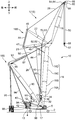
- FIG. 1 is a schematic side view of a first embodiment (a crane 1A) of a crane 1 according to the present embodiment.
- the first mode is also called an STD-LF mode (standard luffing mode).
- FIG. 2 is a schematic side view of a second mode (the crane 1B) of the crane 1 according to the present embodiment.
- the second mode is also called an SHL-LF mode (super heavy lift luffing mode).
- the crane 1 is changed to the SHL-LF type crane 1B shown in FIG. 2 by adding or changing other members while sharing some members of the STD-LF type crane 1A shown in FIG. be able to.
- the crane 1 includes a lower traveling body 2 capable of self-traveling, an upper revolving body 4 as a crane body mounted on the lower traveling body 2 so as to be able to pivot about a vertical axis, and an upper revolving body 4. And a cab 5 (operator cab) provided at the front end of the vehicle to allow a worker who operates the crane 1 to board the vehicle, and an attachment 10 (an undulating body) attached to the front of the upper revolving unit 4 for performing a lifting operation. ), A mast 12 attached to the upper revolving unit 4 behind the attachment 10, and a counterweight 13 mounted on a rear portion of the upper revolving unit 4 to maintain the balance of the crane 1 and improve stability. And.
- front, rear, left and right are defined with reference to the upper revolving unit 4 that turns with respect to the lower traveling unit 2.
- the direction in which the boom 16 of the attachment 10 described later falls down is the front, and the opposite direction is the rear.
- the left and right sides are determined based on the front defined by the definition.
- the attachment 10 includes a boom 16, a jib 18, a rear strut 21, a front strut 22, a pair of left and right boom back stops 23, a pair of left and right jib back stops 24, a pair of left and right strut back stops 25, It has a pair of right and left strut guy links 26, a pair of left and right jib guy links 28, a main hook 57, and an auxiliary hook (not shown).
- the boom 16 is attached to the front part of the upper swing body 4 so as to be rotatable in a rising direction and a falling direction around a horizontal axis (first rotation axis).
- the boom 16 is a so-called lattice type.
- the boom 16 can be disassembled into a plurality of parts in the longitudinal direction. That is, the boom 16 has a lower boom 16A, one or more (two in the illustrated example) intermediate booms 16B, 16C, and an upper boom 16D, and these lower boom 16A, intermediate booms 16B, 16C, and upper It can be disassembled into a boom 16D.
- the lower boom 16A is a part including the base end of the boom 16, and is provided at a front portion of the upper revolving unit 4 so as to be rotatable around an axis (first rotation axis) extending in the left-right direction of the upper revolving unit 4. Be linked. Specifically, the base end of the lower boom 16A corresponding to the base end of the boom 16 is connected to the front part of the upper swing body 4 by the boom foot pin 17 extending in the left-right direction. The lower boom 16A is rotatable. A pair of left and right boom backstops 23 are interposed between the lower boom 16A and the upper swing body 4.
- a pair of left and right boom backstops 23 are provided on the upper swing body 4, and come into contact with the left and right sides of the lower boom 16A when the boom 16 takes the standing posture shown in FIG. This abutment restricts the boom 16 from being moved rearward by a strong wind or the like.
- the intermediate booms 16B and 16C are detachably attached to the distal end side of the lower boom 16A in that order.
- the upper boom 16D is detachably attached to the distal end side of the intermediate boom 16C.
- the upper boom 16D has an upper boom main body 19A having a lattice structure connected to the intermediate boom 16C, and a boom head 19B connected to a tip of the upper boom main body 19A.
- the boom head 19B corresponds to the tip of the boom 16.
- the jib 18 is of a lattice type and has a distal end portion (boom) of the boom 16 so as to be rotatable about the axis extending in the left-right direction (a second rotation axis parallel to the first rotation axis) in a rising direction and a falling direction. Head 19B). Specifically, the jib 18 is one end in the longitudinal direction of the jib 18 and attached to the boom head 19B so as to be rotatable around the axis extending in the left-right direction, and a side opposite to the base end. And a front end portion which is an end portion. The jib 18 can also be disassembled into a plurality of parts in the longitudinal direction.
- the jib 18 has a lower jib 18A, one or more (one in the illustrated example) intermediate jib 18B, and an upper jib 18C, which are disassembled into a lower jib 18A, an intermediate jib 18B, and an upper jib 18C. It is possible.
- the lower jib 18A is a part including the base end portion of the jib 18, and is disassembled in the longitudinal direction to disassemble the jib 18 into the middle jib 18B and the upper jib 18C which are portions on the distal end side of the jib 18 with respect to the lower jib 18A.
- the lower jib 18A can be separated.
- the lower jib 18A is connected to a boom head 19B so as to be rotatable around the axis extending in the left-right direction.
- the base end of the lower jib 18A corresponding to the base end of the jib 18 is connected to the boom head 19B by the jib foot pin 29 extending in the left-right direction, and the lower jib 18A is connected to the boom 16 around the jib foot pin 29. It is rotatable with respect to this.
- the boom head 19B has a jib mounting portion 19C at the most forward position of the boom head 19B when the boom 16 stands up as shown in FIG.
- a pin hole is provided in the jib mounting portion 19C, and a pin hole is also provided in the base end of the lower jib 18A.
- the jib foot pin 29 is inserted into the pin hole of the lower jib 18A so as to extend in the left-right direction in a state where the pin hole of the jib mounting portion 19C and the pin hole of the base end of the lower jib 18A coincide with each other.
- the base end is connected to the jib mounting portion 19C via the jib foot pin 29.
- the lower jib 18A is detachable from the jib mounting portion 19C of the boom head 19B. That is, the lower jib 18A can be separated from the jib mounting portion 19C by extracting the jib foot pin 29 from the pin hole.
- a pair of left and right jib backstops 24 are interposed between the lower jib 18A and the boom head 19B.
- the pair of left and right jib backstops 24 are attached to the boom head 19B, and come into contact with the left and right sides of the lower jib 18A when the jib 18 takes an upright posture as shown in FIG. This abutment restricts the jib 18 from being pushed backward by strong wind or the like.
- the middle jib 18B is detachably attached to the distal end of the lower jib 18A.
- the upper jib 18C is detachably attached to the distal end side of the intermediate jib 18B.
- the tip of the upper jib 18C corresponds to the tip of the jib 18.
- the rear strut 21 is attached to the boom head 19B so as to be rotatable around the axis extending in the left-right direction.
- the rear strut 21 has one end in the longitudinal direction and a rear strut base end 21A attached to the boom head 19B, and a rear strut tip 21B which is an end opposite to the rear strut base end 21A.
- the rear strut 21 is held in such a posture as to protrude from the boom head 19B in a direction in which the boom 16 stands (to the left in FIG. 1).
- a pair of left and right strut backstops 25 and a pair of right and left strut guy links 26 are interposed between the rear strut 21 and the boom 16.
- the strut backstop 25 is interposed between the upper boom 16D and an intermediate portion of the rear strut 21 and supports the rear strut 21 from below.
- the strut guy link 26 is stretched to connect the rear strut tip 21B and the lower boom 16A, and regulates the position of the rear strut 21 by the tension.
- the front strut 22 is attached to the lower jib 18A so as to be rotatable around the axis extending in the left-right direction.
- the front strut 22 has one longitudinal end and a front strut proximal end 22A attached to the proximal end of the jib 18, and a front strut distal end that is an end opposite to the front strut proximal end 22A. 22B.
- a pair of left and right jib guide links 28 are stretched between the front strut tip 22B and the tip of the jib 18 so as to connect them.
- the angle between the front strut 22 and the jib 18 is restricted so as not to be further enlarged.
- the front strut tip 22B is pulled toward the rear strut tip 21B, so that the angle between the front strut 22 and the jib 18 is maintained, in other words, the distance between the front strut 22 and the jib 18 is maintained.
- the front strut 22 and the jib 18 rotate rearward around the jib foot pin 29 while maintaining the relative positional relationship.
- the above-described rear strut 21 is disposed rearward of the front strut 22. That is, the rear strut 21 is rotated around the axis extending in the left-right direction by the boom head 19B at a position behind the attachment position of the jib 18 to the boom head 19B and at a position behind the attachment position of the front strut 22 to the lower jib 18A. It is movably mounted.
- the mast 12 has a mast proximal end 12A attached to the upper swing body 4 at one end in the longitudinal direction, and a mast distal end 12B which is an end opposite to the mast proximal end 12A.
- the mast base end 12A is connected to the upper swing body 4 so as to be rotatable around the axis extending in the left-right direction.
- the mast tip 12B is connected to the boom head 19B via a pair of left and right boom guy lines 66. This connection causes the rotation of the mast 12 and the rotation of the boom 16 to cooperate.
- the main hook 57 and the auxiliary hook are each suspended from the end of the jib 18 to suspend a load.
- the crane 1 (1A) of the present embodiment includes a boom hoisting winch 30 for raising and lowering the boom 16, a jib hoisting winch 32 for rotating the jib 18 with its base end as a fulcrum, and raising and lowering the jib 18. It further includes a main winding winch 34 and an auxiliary winding winch 36 for lifting and lowering the suspended load.
- the boom hoisting winch 30, the auxiliary winding winch 36, and the main winding winch 34 are arranged on the upper swing body 4 in this order from back to front.
- the jib hoisting winch 32 is provided on the lower boom 16A.
- the boom hoisting winch 30 winds and unwinds the boom hoisting rope 38. Then, the boom hoisting rope 38 is routed so that the mast 12 is rotated by the winding and unwinding.
- a sheave block 40 including a plurality of sheaves arranged in the left-right direction is provided at the mast distal end portion 12B, and the rear end of the upper revolving unit 4 is similarly arranged in the left-right direction.
- Block 42 including a plurality of sheaves arranged as described above.
- a boom hoisting rope 38 pulled out from the boom hoisting winch 30 is stretched between the sheave blocks 40 and 42.
- the boom hoisting winch 30 winds or unwinds the boom hoisting rope 38, so that the distance between the two sheave blocks 40 and 42 changes, whereby the mast 12 and the boom 16 interlocking with the mast 12 are changed. Rotates and stands up and falls down.
- the boom hoisting rope 38 is indirectly connected to the distal end of the boom 16 via the mast 12 and the boom guy line 66.
- the boom hoisting winch 30 and the boom hoisting rope 38 constitute the boom drive unit 16S of the present invention.
- the boom drive section 16S rotates the boom 16 around the boom foot pin 17 in the rising direction and the falling direction.
- the jib hoisting winch 32 winds and pays out the jib hoisting rope 44. Then, the jib hoisting rope 44 is routed such that the front strut 22 is rotated by the winding and feeding.
- a first guide sheave 45 for raising and lowering the jib is provided on the lower boom 16A
- a second guide sheave 46 for raising and lowering the jib is provided on the upper boom 16D.
- a sheave block 47 including a plurality of sheaves arranged in the left-right direction is provided at the rear strut tip 21B, and the sheave block 47 is similarly arranged in the left-right direction at the front strut tip 22B.
- a sheave block 48 including a plurality of sheaves is provided.
- the jib hoisting rope 44 pulled out from the jib hoisting winch 32 is sequentially hung on the jib hoisting first guide sheave 45 and the jib hoisting second guide sheave 46, and the sheave block 48 of the front strut tip 22B. And the sheave block 47 of the rear strut tip 21B. Accordingly, the winding and unwinding of the jib hoisting rope 44 by the jib hoisting winch 32 changes the distance between the two sheave blocks 47 and 48, thereby rotating the front strut 22 and the jib 18 interlocking therewith. Stand up and fall down.
- the jib hoisting winch 32 raises the jib 18 by winding the jib hoisting rope 44 to rotate the front strut 22 so that the front strut tip 22B approaches the rear strut tip 21B.
- the front strut tip 22B is turned away from the rear strut tip 21B by rotating the jib hoisting rope 44 while turning the jib 18 in the direction in which the jib 18 is turned down.
- the jib hoisting rope 44 is indirectly connected to the distal end of the jib 18 via the front strut 22 and the jib guy link 28.
- the jib hoisting winch 32, the jib hoisting rope 44, the rear strut 21, the front strut 22, and the jib guy link 28 constitute the jib driving unit 18S of the present invention.
- the jib driving unit 18S rotates the jib 18 around the jib foot pin 29 in the rising direction and the falling direction.
- the main winding winch 34 hoists and lowers the suspended load by the main winding rope 50.
- a first main winding guide sheave 52 is provided at a position near the base end of the rear strut 21 so as to be rotatable around the axis extending in the left-right direction.
- the two main winding guide sheaves 53 are provided rotatably around the axis extending in the left-right direction.
- a third main winding guide sheave 54 is provided at the end of the jib 18 so as to be rotatable around the axis extending in the left-right direction.
- the left and right guide sheaves 54 are positioned adjacent to the third main winding guide sheave 54.
- a main winding sheave block including a plurality of main winding point sheaves 56 arranged in a row is provided.
- the main winding rope 50 pulled out from the main winding winch 34 is sequentially hung on the first, second and third main winding guide sheaves 52, 53, 54, and the main winding point of the main winding sheave block.
- the sheave is wound around the sheave 56 and a sheave 58 of a sheave block provided on a main hook 57 as a hanging tool. Therefore, when the main winding winch 34 winds or unwinds the main winding rope 50, the distance between the main winding point sheave 56 and the sheave 58 of the main hook 57 changes, thereby changing the tip of the jib 18.
- the main hook 57 connected to the main winding rope 50 hung from the ceiling is wound up and down.
- the main hook 57 constitutes the suspension device of the present invention.
- the main hook 57 hangs down from the tip of the jib 18 and is connected to a suspended load.
- the auxiliary winch 36 hoists and lowers the suspended load by the auxiliary rope 60.
- the crane 1 includes, in addition to the auxiliary winding winch 36, a first auxiliary winding guide sheave 62, a second auxiliary winding guide sheave 63, a third auxiliary winding guide sheave 64, and an auxiliary sheave. 65.
- the functions of the members related to the auxiliary winding are the same as the functions of the members related to the main winding.
- the crane 1 further includes a pair of left and right wheels 65S (FIGS. 8 and 9).
- the wheel 65 ⁇ / b> S is arranged coaxially with the auxiliary sheave 65 at the tip of the jib 18.
- the outer diameter of the wheel 65S is set larger than the outer diameter of the auxiliary sheave 65.
- the wheels 65S roll on the ground when the boom 16 and the jib 18 of the crane 1 are laid down on the ground. As a result, the movement of the boom 16 and the jib 18 during the assembling and disassembling operations of the crane 1 can be easily performed.
- the crane 1B (crane 1) of the SHL-LF type shown in FIG. 2 will be described.
- the crane 1B is different from the crane 1A in that the crane 1B includes a lattice mast 90, a boom hoisting winch 91, a guy link 92, a boom hoisting rope 93, a guy link 94, and a weight guy link 95. And a pallet weight 96. Therefore, hereinafter, the difference will be mainly described, and the description of the common points will be omitted.
- the lattice mast 90 is rotatably supported by the upper swing body 4 behind the boom 16 and between the mast 12 and the boom 16.
- the lattice mast 90 is fixed to a position at a predetermined angle with respect to the ground in the upper swing body 4 and serves as a support for the rotation of the boom 16.
- the boom hoisting winch 91 is disposed on the base end side of the lattice mast 90, and winds and unwinds the boom hoisting rope 93.
- the guy link 92 and the boom hoisting rope 93 are arranged so as to connect the tip of the boom 16 and the tip of the lattice mast 90. Specifically, the guy link 92 extends from the tip of the boom 16 toward the tip of the lattice mast 90.
- the boom hoisting rope 93 After being pulled out from the boom hoisting winch 91, the boom hoisting rope 93 is wound a plurality of times between a sheave block 97 provided at the tip of the guy link 92 and a sheave block 98 provided at the tip of the lattice mast 90.
- Guy link 94 connects the tip of mast 12 and the tip of lattice mast 90.
- the weight guide link 95 connects the tip of the lattice mast 90 and the pallet weight 96.
- the pallet weights 96 are arranged at intervals behind the upper swing body 4 and maintain the balance of the crane 1B provided with the lattice mast 90.
- the mast hoisting rope 9A is wound between the tip of the mast 12 and the upper swing body 4.
- a mast hoisting winch 9B is provided on the base end side of the mast 12.
- the mast hoisting rope 9A is wound and unwound by the mast hoisting winch 9B, whereby the mast 12 and the lattice mast 90 are integrally rotated.
- the distance between the sheave block 97 and the sheave block 98 is changed by the boom hoisting winch 91 provided at the base end of the lattice mast 90 winding and unwinding the boom hoisting rope 93.
- the boom 16 rotates relatively to the lattice mast 90.
- rotation (undulation) of the boom 16 is realized.
- the main winding winch 34 and the auxiliary winding winch 36 are fixed to the lower boom 16A of the boom 16, but the arrangement of these winches is limited to the embodiments of FIGS. is not.
- the lattice mast 90, the boom hoisting winch 91, the guy link 92, and the boom hoisting rope 93 constitute a boom drive unit of the present invention.
- a long jib 18 is connected to the tip of a long boom 16. Then, when such a self-standing operation or a falling operation of the crane 1 is performed, the crane 1 is prevented from overturning.
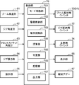
- FIG. 3 is an electrical block diagram of a configuration for controlling the crane 1 (1A, 1B) according to the present embodiment.
- the crane 1 includes a control unit 70 that comprehensively controls the operation of the crane 1, a boom angle meter 81 (boom angle detection unit), a jib angle meter 82 (jib angle detection unit), and a front strut angle meter 83. , A jib tension meter 84, an operation unit 85 (input unit), a display unit 86, and a notification buzzer 87.
- the control unit 70 includes a CPU (Central Processing Unit), a ROM (Read Only Memory) storing a control program, a RAM (Random Access Memory) used as a work area of the CPU, and the like.
- the control unit 70 includes a boom goniometer 81, a jib goniometer 82, a front strut goniometer 83, a jib tensiometer 84, an operation unit 85, a boom hoisting winch 30 (boom hoisting winch 91), a jib hoisting winch 32, The main winding winch 34 and the like are electrically connected.
- the control unit 70 may be electrically connected to a hydraulic circuit (for example, a control valve) for driving a hydraulic motor (not shown) connected to these winches.
- the boom angle meter 81 is provided at the base end of the boom 16, detects a ground angle ⁇ b of the boom 16 (see FIG. 9), outputs a signal corresponding to the ground angle ⁇ b, and inputs the signal to the control unit 70. I do.
- the jib goniometer 82 is provided at the tip of the jib 18, detects the ground angle ⁇ j of the jib 18 (see FIG. 5), outputs a signal corresponding to the ground angle ⁇ j, and outputs the signal to the controller 70. To enter.
- the front strut angle meter 83 is provided at the base end of the front strut 22, detects a ground angle (not shown) of the front strut 22, outputs a signal corresponding to the ground angle, and outputs a signal corresponding to the ground angle. To enter.
- the jib tension meter 84 is provided at the tip of the jib 18 and partially holds the tip of the jib guy link 28.
- the jib tensiometer 84 detects the tension Tm of the jib guy link 28 extending between the tip of the front strut 22 and the tip of the jib 18.
- the operation unit 85 is disposed inside the cab 5 and receives various operations by the operator.
- the operation unit 85 includes a plurality of operation levers and a touch panel type or button type input unit.
- the plurality of operation levers are used to drive the traveling operation of the lower traveling unit 2, the pivoting operation of the upper revolving unit 4, the winch 30 for boom undulation, the winch 32 for jib undulation, the main winch 34, and the auxiliary winch 36.
- the input unit receives operation information of the crane 1 and numerical values of parameters. As an example, the input unit receives length information on the length of the boom 16 and the length of the jib 18, and receives weight information on the weight of the counterweight 13 and the pallet weight 96.
- the display unit 86 is arranged inside the cab 5 like the operation unit 85.
- the display unit 86 displays various types of operation information of the crane 1.
- the notification buzzer 87 is disposed inside the cab 5 and outside the cab 5, and reports predetermined warning information to a worker riding on the cab 5 or a worker around the crane 1.
- control unit 70 executes a mode switching unit 701, a drive control unit 702, an operation control unit 703, a calculation unit 704, a determination unit 705 (an angle condition determination unit, a jib It functions to include a contact state determination unit), a storage unit 706, and an information output unit 707.
- the mode switching unit 701 switches a plurality of modes of the operation restricting unit 703.
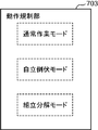
- FIG. 4 is a schematic diagram showing each mode of the operation restricting unit 703 of FIG.
- the operation restricting unit 703 has a normal operation mode, a self-standing fall mode (also referred to as a fall allowance mode and a self-sustain allow mode), and an assembly and disassembly mode.
- the normal operation mode is a mode that allows the crane 1 to perform a normal operation in the working posture of the crane 1 in which the boom 16 stands on the upper swing body 4 and the jib 18 stands on the boom 16. is there.
- the self-standing fall mode is a mode in which the crane 1 allows the self-standing operation and the falling operation. Specifically, the crane 1 changes the posture from the work posture until the boom 16 and the jib 18 fall forward from the work posture and the tip end of the jib 18 reaches the ground posture. This is a mode that allows Further, the self-standing fall mode is also a mode that allows the crane 1 to change its posture from the above-mentioned fall posture to the above-mentioned work posture (self-stand).
- the assembling / disassembling mode is a mode in which all operations that can be executed in the independent falling mode are allowed, and other operations that are not allowed in the independent falling mode are allowed.
- the jib 18 in the disassembly mode, the jib 18 is allowed to be detached from the boom 16, and the boom 16 is allowed to be detached from the upper rotating body 4.
- the jib 18 In the disassembly mode, the jib 18 is allowed to be mounted on the boom 16, and the boom 16 is allowed to be mounted on the upper swing body 4.
- the mode switching of the operation restricting unit 703 by the mode switching unit 701 is performed according to a command input from the operation unit 85 by an operator. As described later, when a predetermined condition is satisfied, the mode of the operation restricting unit 703 is switched by the mode switching unit 701.
- the drive control unit 702 responds to an operation input to the operation unit 85 and controls the crane 1 including the boom hoisting winch 30 (boom hoisting winch 91), the jib hoisting winch 32, the main winding winch 34, and the like.
- the driving of the driving member is controlled.
- the drive control unit 702 outputs a drive command signal (drive signal) to a hydraulic circuit connected to an electric motor or a hydraulic motor for rotating each winch included in the crane 1.
- the operation restricting unit 703 restricts the rotation of the boom 16 and the jib 18 according to a preset mode.
- the operation restricting unit 703 has a function of restricting these operations as a safety device when predetermined conditions are satisfied when the crane 1 performs the falling operation or the independent operation.
- the operation restricting unit 703 restricts the rotation of the boom 16 and the jib 18 so that the tip of the jib 18 is included in a work allowable range set according to the load of the suspended load in the working posture of the crane 1. (Moment limiter function).
- the movement restricting unit 703 moves the tip end of the jib 18 outside the allowable working range regardless of the load of the suspended load.
- the crane 1 is allowed to change its posture from the working posture to the lying posture.
- the movement restricting portion 703 is defined by an extension of the center line of the boom 16 and the center line of the jib 18 when viewed from a direction (left-right direction) parallel to the rotation axis of the boom 16 during the crane 1 falling down.
- the operation restricting unit 703 outputs a raising and lowering restriction signal for restricting the raising and lowering operations of the boom 16 and the jib 18. In this case, the jib 18 is allowed to fall.
- the above-described jib boom angle condition is not satisfied and the contact determination condition described later is satisfied. If the determination unit 705 determines that the boom 16 has not been moved, it outputs an up-and-down restriction signal for restricting the up-and-down operation of the boom 16 and the up-down operation of the jib 18. The above-described restricting operation performed by the operation restricting unit 703 will be described later in detail.
- the calculation unit 704 executes calculation processing in various flows executed by the control unit 70.
- the calculating unit 704 calculates and determines the above-described jib offset angle ⁇ m from the ground angle ⁇ b of the boom 16 detected by the boom angle meter 81 and the ground angle ⁇ j of the jib 18 detected by the jib angle meter 82.
- the storage unit 706 stores the offset limit angle ⁇ s in advance and can output the offset limit angle ⁇ s.
- the storage unit 706 stores a plurality of the offset limit angles ⁇ s in accordance with a combination of the length of the jib 18, the length of the boom 16, and the weight of the counterweight 13 (pallet weight 96). And outputting a predetermined offset limit angle ⁇ s from the plurality of offset limit angles ⁇ s according to the length information and the weight information input to the operation unit 85.
- the storage unit 706 stores the offset limit angle ⁇ s in the STD-LF specification shown in FIG. 1 and the SHL-LF specification shown in FIG. 2 in a table format. Note that the storage unit 706 may store and output the offset limit angle ⁇ s according to the length information of the boom 16 and the jib 18 irrespective of the weight information of the counterweight 13 (pallet weight 96).
- the determination unit 705 performs a determination process in various flows executed by the control unit 70. In particular, the determination unit 705 determines that the jib boom angle condition is satisfied when the jib offset angle ⁇ m determined by the calculation unit 704 is larger than the offset limit angle ⁇ s output from the storage unit 706. On the other hand, when the jib offset angle ⁇ m is smaller than the offset limit angle ⁇ s, it is determined that the jib boom angle condition is not satisfied. Further, the determination unit 705 also has a function as a jib contact state determination unit that determines whether the state of the jib satisfies a predetermined contact determination condition.
- the contact determination condition is a predetermined condition for determining that the tip of the jib 18 is normally in contact with the ground.
- the contact determination condition according to this embodiment is that the tension Tm of the jib guy link 28 detected by the jib tensiometer 84 is equal to or less than a certain value, as described later in detail. In other words, when the tension Tm is equal to or greater than a predetermined value, it is determined that a force is applied to the jib 18 such that the jib 18 is lifted from the ground against the weight of the jib 18 or the like. It is determined that the distal end of No. 18 is not in a normal contact state.
- the information output unit 707 receives the up-and-down regulation signal from the operation regulation unit 703, and outputs notification information and a signal corresponding to the information to the display unit 86 and the notification buzzer 87.
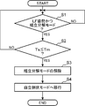
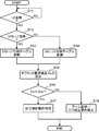
- FIG. 5 is a flowchart showing a process for the crane 1 (1A, 1B) according to the present embodiment to shift from the assembly and disassembly mode to the independent standing mode.
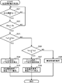
- FIG. 6 and FIG. 7 are flowcharts showing processing in the crane 1 according to the present embodiment in the free-standing falling mode.
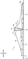
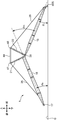
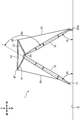
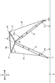
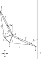
- FIG. 8 to FIG. 14 are process diagrams showing the self-standing falling operation of the crane 1 according to the present embodiment.
- mode switching unit 701 executes a mode switching determination process from the assembly work mode to the self-standing fall mode for the mode of operation restricting unit 703. I do.
- the mode switching determination process is executed at predetermined intervals while the crane 1 is in use.
- the determination unit 705 determines whether the crane 1 is in the LF posture (ruffing posture, corresponding to the work posture in FIG. 1) and the execution mode of the crane 1 is the assembly disassembly mode. (Step S1).
- the determination unit 705 stores the tension Tm of the jib guy link 28 detected by the jib tensiometer 84. It is determined whether the tension is equal to or greater than the tension threshold Ts stored in the unit 706 (step S2).
- step S2 if Ts ⁇ Tm is satisfied (YES in step S2), the tension Tm of the jib guy link 28 is sufficiently large, and the jib 18 is supported by the boom 16, in other words, the tip of the jib 18 Since it is determined that the part is floating above the ground against the weight of the jib 18 or the like, the mode can be shifted from the disassembly / disassembly mode to the independent standing mode. Therefore, the mode switching unit 701 cancels the assembling / disassembling mode (step S3), and shifts to the self-standing falling mode (step S4).
- step S1 If the crane 1 is not in the LF posture or in the disassembly mode in step S1 (NO in step S1), the determination in step S1 is repeated by the determination unit 705. Also, in step S2, when Ts> Tm (NO in step S2), steps S1 and S2 are repeated.
- the transition to the self-standing fall mode by the mode switching unit 701 is not limited to the processing in FIG.
- a worker in the cab 5 may input a command to shift to the self-standing fall mode through the operation unit 85, and the mode switching unit 701 may switch the mode of the operation restricting unit 703 in response to the command.
- the determination unit 705 further determines whether or not the crane 1 has the STD-LF specification (step S12).
- the information regarding whether the crane 1 is set to the STD-LF specification (FIG. 1) or the SHL-LF specification (FIG. 2) is input by the operator from the operation unit 85 and stored in the storage unit 706. ing. If the crane 1 is not in the LF posture in step S11 (NO in step S11), the determination in step S11 is repeated.
- step S12 when the crane 1 has the STD-LF specification shown in FIG. 1 (YES in step S12), the operation restricting unit 703 reads the offset limit angle from the STD-LF specification table stored in the storage unit 706. ⁇ s (threshold angle) is obtained (step S13).
- the operation restricting unit 703 acquires the offset limit angle ⁇ s from the SHL-LF specification table stored in the storage unit 706. (Step S14).
- the offset limit angle ⁇ s appropriately set for the current specifications of the crane 1 is determined (step S15). Since the balance of the crane 1 is different between the STD-LF specification and the SHL-LF specification, different offset limit angles ⁇ s are set.
- the calculation unit 704 calculates the current jib offset angle ⁇ m from the ground angle ⁇ b of the boom 16 and the ground angle ⁇ j of the jib 18. Then, the determination unit 705 compares the magnitude relationship between the calculated jib offset angle ⁇ m and the offset limit angle ⁇ s (step S16).
- ⁇ m ⁇ ⁇ s YES in step S16
- the jib 18 is in a posture bent sufficiently downward with respect to the boom 16 (the jib boom angle condition is satisfied). For this reason, the operation restricting unit 703 allows the crane 1 to stand alone and fall down in the stand-alone falling mode (step S17, effective stand-alone falling operation).
- step S16 when ⁇ m ⁇ s, the jib 18 is located at a position closer to the extension of the center line of the boom 16 than when ⁇ m ⁇ ⁇ s (the jib boom angle condition is not satisfied). In this state, if the crane 1 is self-sustained and falls down, there is a concern that the crane 1 may fall forward. Therefore, the operation restricting unit 703 restricts (restricts) the operation of the boom 16 and the jib 18 (step S18).
- step S17 of FIG. 6 when the operation restricting unit 703 allows the crane 1 to stand up and fall down, the crane 1 is allowed to stand alone or fall down while the operator operates the operation unit 85. Even after the self-standing operation or the falling operation of the crane 1 is started, if the positional relationship (jib offset angle ⁇ m) between the boom 16 and the jib 18 of the crane 1 again becomes unstable, It is necessary to regulate the operation of the crane 1 in order to prevent the crane 1 from overturning. Therefore, the operation restricting unit 703 continuously executes the processing shown in FIG. 7 even during the independent operation or the falling operation of the crane 1.
- the determination unit 705 determines the current mode of the operation restriction unit 703 (step S21 in FIG. 7). Here, if the operation restricting unit 703 is set to the self-standing fall mode (YES in step S21), the determining unit 705 again compares the magnitude relationship between the latest jib offset angle ⁇ m and the offset limit angle ⁇ s (step S22). ). If ⁇ m ⁇ s (YES in step S22), the jib offset angle ⁇ m is too small, and the crane 1 may be overturned.
- the determination unit 705 compares the magnitude relationship between the tension Tm of the jib guy link 28 and the first threshold tension Ts1 set in advance and stored in the storage unit 706 (step S23). In step S23 and step S26 to be described later, it is determined whether or not the tip end (wheel 65S) of the jib 18 has landed on the ground G in consideration of a predetermined measurement error in the tension Tm.
- the first threshold tension Ts1 is a threshold set for determining whether the tip of the jib 18 (wheel 65S) is grounded.
- the tension Tm is larger than the first threshold tension Ts1, that is, the contact determination condition is not satisfied, so that the jib guy link 28 is sufficient. It is determined that tension is generated, that is, a levitation force sufficient to cause the wheel 65S disposed at the tip of the jib 18 to float above the ground is acting. In this case, since the jib offset angle ⁇ m is small and the tip of the jib 18 is floating above the ground, the crane 1 may transfer the jib. Therefore, the operation restricting unit 703 restricts at least a part of the operation of the boom 16 and the jib 18 (Step S24).
- the operation restricting unit 703 controls the information output unit 707 to notify the worker in the cab 5 and other workers around the crane 1 of the danger, and relates to the possibility of the crane 1 falling over.
- the information is displayed on the display unit 86 (state warning display). Further, the operation restricting unit 703 causes the notification buzzer 87 to notify a warning buzzer sound (step S25).
- step S23 when Ts1> Tm in step S23, since the tension Tm is smaller than the first threshold tension Ts1, the determination unit 705 determines the tension Tm and the second threshold tension Ts2 smaller than the preset first threshold tension Ts1. A comparison is made (step S26).
- Tm ⁇ Ts2 since the tension Tm of the jib guy link 28 is sufficiently small, the jib guy link 28 is slackened, and the wheel 65S disposed at the tip end of the jib 18 is disengaged. It can be regarded as being in a state of normal contact with the ground.
- the movement restricting unit 703 allows all of the standing operation and the falling operation of the boom 16 and the standing operation and the falling operation of the jib 18 (step S27). Further, the operation restricting unit 703 controls the information output unit 707 to notify the worker in the cab 5 and other workers around the crane 1 of the safety of the crane 1 so that the crane 1 is in a normal state. Is displayed on the display unit 86 (normal state display). In addition, when the notification buzzer 87 has previously issued the warning buzzer sound, the operation restricting unit 703 stops the buzzer sound (step S28).
- the wheel 65S disposed at the tip of the jib 18 is not necessarily placed on the ground in consideration of the measurement error of the tension Tm of the jib guy link 28. It cannot be said that they are in normal contact. In other words, it is clear that at least a force acting in the direction of lifting the wheel 65S from the ground is acting against the weight of the jib 18. Therefore, the operation restricting unit 703 maintains the process of FIG. 7 (one of steps S24, S27, and S29) executed last time. Thereafter, the operation restricting unit 703 ends the processing in FIG. 7 and repeats the processing in FIG. 7 at a predetermined interval (for example, several seconds).
- a predetermined interval for example, several seconds
- step S18 in FIG. 6 and step S24 in FIG. 7, the operation restricting unit 703 restricts the operation of the boom 16 and the jib 18. Specifically, when the jib boom angle condition is not satisfied during the execution of the self-supporting falling mode, the operation restricting unit 703 winds the boom hoisting rope 38 (the boom hoisting rope 93) around the drive control unit 702. A signal that regulates take-out and extension (raising operation and boom operation of the boom 16) and winding of the jib hoisting rope 44 (raising operation of the jib 18) is output as the above-mentioned fall regulation signal. At this time, the extension of the jib hoisting rope 44 (falling operation of the jib 18) is allowed.
- a jib hoisting rope 44 is wound a plurality of times between a sheave block 47 arranged at the tip of the rear strut 21 and a sheave block 48 arranged at the tip of the front strut 22. Therefore, the jib 18 can be raised and lowered by the winding and unwinding of the jib hoisting rope 44 by the jib hoisting winch 32.
- a boom guy line 66 is connected to the end of the boom 16 in advance, and the boom hoisting rope 38 is wound by the boom hoisting winch 30 and fed out. The boom 16 can be raised and lowered with the mast 12.
- the jib guy link 28 In the state shown in FIG. 8, the jib guy link 28 is loose, and the tension Tm of the jib guy link 28 detected by the jib tensiometer 84 (FIG. 3) is less than the second threshold tension Ts2 described above. .
- the jib offset angle ⁇ m is equal to zero. For this reason, in the processing in the independent falling mode shown in FIG. 6, the independent falling operation is permitted through steps S11, S12, S13, S15, S16, and S17.
- the offset limit angle ⁇ s determined in step S15 is 45 degrees.
- the jib offset angle ⁇ m is about 30 degrees.
- the process proceeds from step S22 to S23, but since the tension Tm of the jib guy link 28 is still less than the second threshold tension Ts2, the process proceeds to steps S27 and S28. Therefore, the standing operation of the boom 16 is allowed.
- step S22 If the boom 16 continues to be erected from the state shown in FIG. 9, the jib guy link 28 will eventually be tensioned and the tension Tm will increase as shown in FIG. In FIG. 10, since the jib offset angle ⁇ m is 44 degrees, the process of FIG. 7 proceeds from step S22 to S23. If the worker continues the raising operation of the boom 16, the tension Tm becomes larger than the first threshold tension Ts1. Therefore, the process proceeds from step S23 in FIG. 7 to S24 and S25, and the operation restricting unit 703 restricts the standing operation of the boom 16, the falling operation, and the standing operation of the jib 18.
- the crane 1 may fall forward, so such a phenomenon is prevented beforehand by the restriction processing by the operation restricting unit 703.
- the reason why the falling operation of the boom 16 (extending the rope 44 for raising and lowering the jib) is also limited is that when the boom 16 is lowered while the tip end of the jib 18 is lifted off the ground, the upper swing body 4 and the lower This is because the moment in the direction in which the traveling body 2 is lifted off the ground increases, and the crane 1 may similarly fall over. Further, in order to prevent the tip of the jib 18 from further rising, the rising of the jib 18 (winding of the jib up / down rope 44) is restricted.
- the crane 1 is brought into the posture shown in FIG. In FIG. 11, the jib offset angle ⁇ m is about 120 degrees. In this case, since ⁇ m> ⁇ s (45 degrees), NO is determined in step S22 in FIG. 7, and the standing of the boom 16 is continuously allowed. Then, as shown in FIG. 12, the jib offset angle ⁇ m is sufficiently large even if the tip end of the jib 18 floats from the ground as shown in FIG. Thereafter, as shown in FIGS. 13 and 14, the boom 16 continues to stand up, and the crane 1 is set to the working posture as shown in FIG. In FIG.
- the jib offset angle ⁇ m is 60 degrees
- the jib offset angle ⁇ m is 40 degrees.
- the operations of the boom 16 and the jib 18 are restricted in steps S24 and S25, but the ground angle ⁇ b of the boom 16 is already at a predetermined angle (boom limit angle, for example, 65 degrees).
- the crane 1 is included in the allowable work range, so that the above-described moment limiter function is operating. Therefore, the operation restricting unit 703 has forcibly released the processing shown in FIG.
- the restriction process executed by the operation restricting unit 703 is a boom limit angle in which the ground angle ⁇ b of the boom 16 is set in advance. (65 degrees) It may be performed only in the following cases.
- the operation restricting unit 703 controls the operations of the boom 16 and the jib 18 in step S24 of FIG. Restrict based on S25. In this case, when the jib offset angle ⁇ m becomes larger than the offset limit angle ⁇ s due to the falling down operation of the jib 18, the operation restricting unit 703 can restart the upright operation of the boom 16.
- the execution mode of the crane 1 is directly changed from the normal work mode as described later.
- a mode in which the mode is shifted to the self-sustaining lodging mode may be employed.
- the boom 16 and the jib 18 are allowed to fall down to a range in which the tip end of the jib 18 exceeds a work allowable range (work allowable radius).
- steps S24 and S25 are executed via steps S22 and S23 in FIG.
- the operation restricting unit 703 moves the boom 16 up and down (winding and unwinding the boom up-and-down rope 38) and upright operation of the jib 18 (the jib up-and-down rope 44). Rewind). Note that, as described above, in order to prevent a moment such as to lift the upper revolving superstructure 4, the rising operation of the boom 16 is limited as in the case of the independent operation of the crane 1.
- the boom 16 and the jib 18 are set to the protruding posture on the ground through the states of FIGS. 10 and 9 by extending the boom hoisting rope 38 and extending the jib hoisting rope 44 (FIG. 10). (FIG. 8).
- the jib offset angle ⁇ m falls below the offset limit angle ⁇ s in a state where the tension Tm of the jib guy link 28 exceeds the first threshold tension Ts1 due to an unintended operation of the operator or the like, Restriction processing by the operation restriction unit 703 is performed.
- the operations of the boom 16 and the jib 18 are all permitted in steps S27 and S28 in FIG.
- the restriction process by the operation restricting unit 703 may be performed only when the tip of the jib 18 enters outside the preset work allowable range (radius). In other words, when the tip of the jib 18 is located within the allowable working range, the stability of the crane 1 is maintained, so that it is not necessary to restrict the movement of the boom 16 and the jib 18.
- the operation restricting unit 703 that restricts the rotation of the jib 18 and the boom 16 has the normal work mode and the self-standing fall mode (the fall allowance mode, the self-sustain allow mode).
- the operation restricting unit 703 restricts the rotation of the boom 16 and the jib 18 so that the tip of the jib 18 is included in the allowable operation range set according to the load of the suspended load (moment limiter function). . For this reason, the lifting work of the suspended load can be performed safely.
- the operation restricting unit 703 allows the distal end of the jib 18 to enter the outside of the allowable working range regardless of the load of the suspended load, and according to the determination result of the determining unit 705, 1 allows the posture to be changed between the lying posture and the working posture. Therefore, the possibility of the crane 1 falling over can be determined according to the magnitude of the jib offset angle ⁇ m.
- the operation restricting unit 703 allows the crane to change the posture from the working posture to the falling posture in the self-standing falling mode. If it is determined by the determination unit 705 that the jib boom angle condition is not satisfied during the execution of the self-standing fall mode, the up / down control signal is output regardless of the operation received by the operation unit 85 while allowing the fall operation of the jib 18. The up-and-down operation of the boom 16 and the upright operation of the jib 18 are restricted. In addition, when the determining unit 705 determines that the jib boom angle condition is satisfied, the operation restricting unit 703 allows the up-and-down operation of the boom 16 and the up-and-down operation of the jib 18, respectively.
- the jib boom angle condition is satisfied when the jib offset angle ⁇ m is larger than a preset acute angle limit angle ⁇ s. For this reason, the opening angle between the boom 16 and the jib 18 (the outside angle when the jib offset angle is set to the inside angle) is prevented from becoming too large, and the moment limiter function is released while preventing the crane 1 from tipping over.
- the posture of the crane 1 in the retracted state can be safely changed from the working posture to the lying posture. As a result, it is possible to reduce the burden of the worker on paying attention to the falling of the crane 1 in the falling work.
- the operation restricting unit 703 when the jib boom angle condition is not satisfied in the self-standing fall mode, the operation restricting unit 703 winds and unwinds the boom hoisting rope 38 (boom hoisting rope 93) with respect to the drive control unit 702. And a signal for restricting the winding of the jib hoisting rope 44. For this reason, when the crane 1 is in a posture that is likely to overturn, the driving of the boom hoisting winch 30 (91) and the jib hoisting winch 32 can be quickly restricted.
- the operation restricting unit 703 when the jib boom angle condition is not satisfied at the time of the falling operation in the independent standing mode, the operation restricting unit 703 outputs a signal for displaying warning information to the display unit 86. Therefore, it is possible to promptly notify the worker that the crane 1 is in a position where the crane 1 easily falls. As a result, the crane 1 can be prevented from falling down.
- the operation restricting unit 703 allows the crane to change the posture from the falling posture to the working posture in the self-standing falling mode. Then, the operation restricting unit 703 determines that the jib boom angle condition is not satisfied during the execution of the self-standing fall mode and the state of the jib is the contact determination condition, that is, the jib is in normal contact with the ground. When the determination unit 705 determines that the condition for determining is not satisfied, the up-and-down operation of the boom 16 (the upright operation and the falling operation) and the upright operation of the jib 18 are restricted.
- the operation restricting unit 703 performs the up / down operation of the boom 16 and the up / down operation of the jib 18. Tolerate. For this reason, the state where the tip of the jib 18 is lifted off the ground in the state where the opening angle between the boom 16 and the jib 18 (the outer angle when the jib offset angle ⁇ m is the inside angle) is large is prevented from continuing. As a result, the crane 1 in the state in which the moment limiter function has been released can be safely changed (self-standing) from the falling posture to the working posture while preventing the crane 1 from tipping over. Further, in the self-sustaining work, the burden on the worker of paying attention to the falling of the crane 1 can be reduced.
- the contact determination condition predetermined to determine whether the tip of the jib 18 is normally in contact with the ground means that the tip of the jib 18 is actually in contact with the ground.
- the condition may be a condition for judging that the jib 18 is in contact with the jib 18, or a certain levitation force acting in a direction of lifting the tip of the jib 18 from the ground against the own weight of the jib 18 or the like is applied.
- the state in which the contact pressure of the jib 18 on the ground is significantly reduced may be a condition that excludes such a state from “normal contact”, assuming that the state is not normal contact.
- a jib tensiometer 84 (tension detecting unit) for detecting the tension Tm of the jib hoisting rope 44 is further provided, and the judging unit 705 (jib contact state judging unit) detects by the jib tensiometer 84.
- the determined tension Tm is equal to or less than a preset tension threshold Ts, it may be determined that the contact determination condition for determining that the tip of the jib 18 is normally in contact with the ground is satisfied. .
- the tip of the jib 18 is normally in contact with the ground, in other words, the tip of the jib 18. It can be detected whether or not the part is actually floating from the ground or whether or not there is a possibility of floating.
- the operation restricting unit 703 when both the jib boom angle condition and the contact determination condition are not satisfied during the self-sustaining work, the operation restricting unit 703 outputs a signal for displaying warning information to the display unit 86. I do. Therefore, it is possible to promptly notify the worker that the crane 1 has approached a posture in which the crane 1 is likely to fall. As a result, the crane 1 can be prevented from falling down.
- the jib offset angle ⁇ m can be determined from the detection results of the boom goniometer 81 and the jib goniometer 82 that are usually provided on a crane. As a result, the establishment of the jib boom angle condition can be determined using these goniometers.
- the storage unit 706 stores a plurality of offset limit angles ⁇ s according to a combination of the length of the jib 18 and the length of the boom 16. Therefore, even if the jib 18 or the boom 16 having a different length is attached to the upper revolving unit 4 and the posture in which the crane 1 easily falls over changes, an appropriate offset limit angle ⁇ s can be obtained in accordance with the length information. Can be. Further, the storage unit 706 stores a plurality of offset limit angles ⁇ s in accordance with a combination of the length of the jib 18 and the length of the boom 16 and the weight of the counterweight 13 (pallet weight 96).
- the crane 1 changes its posture from the working posture to the lying posture, and In any case when the posture is changed from the lying posture to the working posture, the crane 1 can be prevented from falling. That is, when the posture of the crane 1 is changed from the working posture to the lying posture, the tension Tm of the jib hoisting rope 44 is often larger than the first threshold tension Ts1, so that it is not always necessary to determine the magnitude of the tension Tm.
- the determination processing as shown in FIG. 7, it is possible to reliably perform the determination for preventing the crane 1 from overturning in any of the independent operation and the falling down operation of the crane 1 by one flow processing.
- the method of changing the posture of the crane 1 restricts the rotation of the boom 16 and the jib 18 in accordance with a preset normal work mode and a self-standing fall mode (a fall allowance mode, a self-sustain allow mode). Is provided.
- a self-standing fall mode a fall allowance mode, a self-sustain allow mode.
- the tip of the jib 18 is subjected to the load of the suspended load.
- the rotation of the boom 16 and the jib 18 is regulated so as to be included in the work allowable range set accordingly, and the crane 1 is allowed to perform normal work.
- the tip of the jib 18 is allowed to enter the outside of the work allowance regardless of the load of the suspended load, and is parallel to the jib foot pin 29 (second rotation axis).
- the jib offset angle ⁇ m which is the angle defined by the extension of the center line of the boom 16 and the center line of the jib 18 when viewed from an appropriate direction, is larger than a preset offset limit angle ⁇ s (threshold angle).
- the crane 1 falls down so that the boom 16 and the jib 18 fall forward from the working posture, and the tip end (wheel 65S) of the jib 18 lands on the ground.
- the posture change between the posture and the work posture is allowed. According to such a method, the lifting operation of the suspended load can be safely performed in the normal operation mode.
- the boom 16 or the jib 18 is not moved while the angle between the boom 16 and the jib 18 is large. Therefore, the crane 1 in the state in which the moment limiter function is released can be safely changed between the working posture and the lying posture while preventing the crane 1 from falling forward.
- the jib boom angle condition that is satisfied when the jib offset angle ⁇ m is larger than the offset limit angle ⁇ s (threshold angle) is satisfied during the falling operation in the self-standing falling mode. If not, only the falling motion of the jib 18 is allowed, and the raising and lowering motion of the boom 16 and the rising motion of the jib 18 are restricted regardless of the operation received by the operation unit 85. On the other hand, when the jib boom angle condition is satisfied in the falling allowance mode, the crane 1 is moved from the working posture to the falling posture while allowing the raising and lowering operations of the boom 16 and the jib 18. Change posture.
- the lifting operation of the suspended load can be performed safely in the normal operation mode, and the crane 1 can be moved from the working position to the falling position in the tilting allowable mode in the tilting allowable mode.
- the boom 16 or the jib 18 is not moved while the angle between the 16 and the jib 18 is large. Therefore, the crane 1 in the state in which the moment limiter function is released can be safely changed from the working posture to the lying posture while preventing the crane 1 from falling forward.
- the crane 1 in the self-standing fall mode allows the crane 1 to change the posture from the fall posture to the working posture.
- the method of changing the posture of the crane 1 is such that the jib offset angle ⁇ m is smaller than the offset limit angle ⁇ s and the tip of the jib 18 normally contacts the ground during the execution of the independent standing mode (independent standing mode).
- the contact determination condition for determining that the vehicle is moving is not satisfied, the rising operation and the falling operation of the boom 16 and the rising operation of the jib 18 are restricted, and at least during the execution of the self-standing falling mode.
- the standing operation and the falling operation of the boom 16 and the standing operation and the falling operation of the jib 18 are allowed. While changing the posture of the crane 1 from the lying posture to the working posture. According to such a posture changing method, during the independent operation of the crane 1, the boom 16 or the jib 18 is moved while the angle between the boom 16 and the jib 18 is large, thereby preventing the crane 1 from falling forward. Meanwhile, it is possible to safely change the posture of the crane 1 in the state where the moment limiter function is released from the lying posture to the working posture.
- the operation restricting unit 703 outputs a signal for restricting the operation of the boom 16 and the jib 18 to the drive control unit 702 when a predetermined condition is satisfied. Is not limited to this.
- the operation restricting unit 703 outputs a signal for displaying predetermined warning information on the display unit 86 or a signal for sounding the notification buzzer 87 as a lodging control signal without outputting the above signal to the drive control unit 702. May be.
- the worker in the cab 5 receives the warning and restricts the operation of the boom 16 and the jib 18, so that the crane 1 can be prevented from falling.
- the mode of the operation restricting unit 703 shifts from the assembly and disassembly mode to the independent standing mode in the falling operation of the crane 1 in which the boom 16 and the jib 18 fall from the working posture of FIG.
- the mode of the operation restricting unit 703 may be shifted from the normal working mode to the self-standing falling mode. In this case, when there is a concern that the crane 1 may fall over, it is desirable that the transition to the self-standing fall mode is restricted.
- the operation restricting unit 703 when the jib boom angle condition is not satisfied in the normal operation mode, the operation restricting unit 703 outputs the mode restriction signal for restricting the switching from the normal operation mode to the self-supporting falling mode (falling allowable mode). It may output to the switching unit 701. According to such a configuration, it is possible to prevent a transition from the normal operation mode to the self-supporting falling mode while keeping the posture in which the crane 1 is likely to fall down.
- the crane 1 has been described as being capable of taking the STD-LF form of FIG. 1 and the SHL-LF form of FIG. 2, but the present invention is not limited to this. Not something.
- the crane 1B may be of the HL-LF type (heavy lift type) without the weight guy link 95 and the pallet weight 96.
- the crane 1 is not limited to one that can be changed to a plurality of forms as shown in FIGS. 1 and 2, and may be one form.
- the offset limit angle ⁇ s is set as a fixed value in accordance with the specifications of the crane 1 (the length of the boom 16 and the jib 18, the weight of the counter weight 13, and the weight of the pallet weight 96).
- the offset limit angle ⁇ s may be stored in the storage unit 706 as a variable for the ground angle ⁇ b of the boom 16 and the ground angle ⁇ j of the jib 18.
- the optimum offset limit angle ⁇ s is applied according to the posture (angle to the ground) of the boom 16 and the jib 18, and the crane 1 can be prevented from tipping over. In other words, when the crane 1 is in a position in which the crane 1 is relatively hard to overturn, the operation of the boom 16 and the jib 18 is prevented from being excessively restricted.
- whether the tip end (wheel 65S) of the jib 18 is in contact with the ground is determined based on the magnitude of the tension Tm of the jib guy link 28.
- the contact state may be determined based on the rotational torque (roller load) of the wheel 65S, the limit switch, and video information acquired by a camera disposed near the wheel 65S.
- the jib offset angle ⁇ m and the offset limit angle ⁇ s are compared to determine that the jib boom angle condition is satisfied.
- the present invention is not limited to this. It is not done.
- An opening angle between the boom 16 and the jib 18 (an outer angle when the jib offset angle ⁇ m is set as an inner angle) may be compared with an opening threshold angle formed of a preset obtuse angle. In this case, when the opening angle is larger than the opening threshold angle, the determining unit 705 determines that the jib boom angle condition is not satisfied.
- the present invention relates to the restriction of at least one of the falling motion and the self-sustaining motion, and the restriction of both the falling motion and the self-sustaining motion is not essential, but the restriction of the self-sustaining motion is performed.
- the aforementioned “contact determination condition” for the restriction can be set arbitrarily.
- the magnitude of the tension Tm of the jib guy link 28 is equal to or less than a certain value, that is, a force that causes the tip of the jib 18 or the like to float from the ground against its own weight acts substantially. Not performed is set as a contact determination condition, but the contact determination condition may be a condition for determining that the tip of the jib 18 is actually in contact with the ground.
- the tip of the jib 18 is in contact with the ground based on the rotational torque (roller load) of the wheel 65S, a limit switch, and video information acquired by a camera disposed near the wheel 65S. May be performed.
- a tension threshold value for the determination can be set freely.
- the threshold value is not a value corresponding to a state in which the jib tip completely floats from the ground as in the above-described embodiment, but is a smaller value, that is, the jib tip is actually placed on the ground.
- the value may be set to a value corresponding to a state in which a levitation force of a certain magnitude or more that is likely to be in contact with but is likely to float from the ground is acting.
- the “contact determination condition predetermined to determine whether the tip of the jib is normally in contact with the ground” in the present invention means that the tip of the jib is actually It may be a condition for determining that the jib is in contact with the ground, or that the tip of the jib is not only in contact with the ground but also that the contact pressure is sufficiently large, that is,
- the condition of “normal contact” may also be that no levitation force that may cause the tip to float from the ground is applied.
- a crane which comprises a crane body, a boom rotatably supported about a first rotation axis horizontal to the crane body, and a crane A jib having a base end rotatably supported about a second rotation axis parallel to the first rotation axis and a tip end opposite to the base end; and moving the boom around the first rotation axis.
- An operation unit that receives a drive control unit that outputs a drive signal that controls the boom drive unit and the jib drive unit, according to the operation input to the operation unit, and is drooped from a tip end of the jib, Contact with suspended load And a jib offset angle, which is an angle defined by an extension of a center line of the boom and a center line of the jib when viewed from a direction parallel to the second rotation axis, from a preset acute angle.
- An angle condition determination unit that determines the establishment of a jib boom angle condition that is satisfied when the angle is greater than a threshold angle, and an operation restriction unit that restricts rotation of the boom and the jib according to a preset mode
- the operation restricting unit has a normal operation mode and a self-standing falling mode. In the normal operation mode, the operation of the crane in which the boom stands up with respect to the crane body and the jib stands up with respect to the boom.
- the operation restricting unit allows the crane to change the posture from the working posture to the lying posture in the self-standing fall mode, and the jig boom angle condition is determined by the angle condition determination unit.
- the jib is allowed to rotate in the falling direction and the boom is turned in the rising direction and the falling direction regardless of the drive signal, and the jib is turned in the rising direction.
- the angle condition determination unit determines that the jib boom angle condition is satisfied, the boom rotates in the upright direction and the falling direction, and the jib rises in the rising direction and the falling direction. It is desirable to allow each of the rotations.
- an operator's cab arranged on the crane main body, which allows an operator operating the crane to board, and a display unit arranged in the operator's cab and displaying predetermined work information
- the operation restricting unit includes a signal for displaying predetermined warning information on the display unit when the angle condition determining unit determines that the jib boom angle condition is not satisfied in the self-standing fall mode. It is desirable to output.
- the operation restricting unit switches from the normal operation mode to the self-standing falling mode. It is desirable to regulate
- the jib is allowed to rotate in the upright direction and the falling direction, but if the jib state does not satisfy the contact determination condition, the jib contacts the jib.
- the state determination unit determines, the jib is allowed to rotate in the falling direction and the boom is turned in the rising and falling directions and the jib is turned in the rising direction regardless of the drive signal.
- the angle condition determination unit determines that the jib boom angle condition is satisfied, regardless of the determination result by the jib contact state determination unit, the boom rotates in the upright direction and the falling direction.
- the above configuration further includes a tension detecting unit that detects a tension of the rope for raising and lowering the jib, wherein the jib contact state determining unit determines that the tension detected by the tension detecting unit is equal to or less than a preset threshold tension. Preferably, it is determined that the contact determination condition is satisfied.
- an operator's cab arranged on the crane main body, which allows an operator operating the crane to board, and a display unit arranged in the operator's cab and displaying predetermined work information
- the operation restricting unit is configured to determine that the jib boom angle condition is not satisfied by the angle condition determining unit and that the contact determining condition is not satisfied by the jib contact state determining unit in the self-standing fall mode. If it is determined, it is desirable to output a signal for displaying predetermined warning information on the display unit.
- a boom angle detector for detecting a ground angle of the boom
- a jib angle detector for detecting a ground angle of the jib, a ground angle of the boom detected by the boom angle detector, and the jib.
- An angle determination unit that determines the jib offset angle from the ground angle of the jib detected by an angle detection unit, and a storage unit that can store the threshold angle in advance and output the threshold angle, further comprising: It is preferable that the angle condition determination unit determines that the jib boom angle condition is satisfied when the jib offset angle determined by the angle determination unit is larger than the threshold angle output from the storage unit. .
- the apparatus further includes an input unit that receives length information on the length of the jib and the length of the boom, and the storage unit includes a plurality of storage units that correspond to a combination of the length of the jib and the length of the boom. It is preferable that the threshold angle is stored, and a predetermined threshold angle is output from the plurality of threshold angles according to the length information input to the input unit.
- the crane body further includes a weight body disposed behind the crane body or behind the crane body to maintain the balance of the crane, and the input unit is configured to provide weight information on a weight of the weight body.
- the storage unit may store the plurality of threshold angles according to a combination of the length of the jib, the length of the boom, and the weight of the weight body, and may be input to the input unit.
- a predetermined threshold angle is output from the plurality of threshold angles according to the length information and the weight information.
- Also provided by the present invention are a crane body, a boom rotatably supported about a first rotation axis horizontal to the crane body, and a tip end of the boom parallel to the first rotation axis.
- a jib having a base end rotatably supported around a second rotation axis and a tip end opposite to the base end; and an operation unit for receiving an operation for driving the boom and the jib.
- a method for changing the posture of the crane having: The method for changing the posture of the crane is to regulate the rotation of the boom and the jib according to a preset normal operation mode and a self-standing falling mode. In the normal operation mode, the boom is moved by the crane body.
- a jib offset angle which is an angle defined by an extension of the center line of the boom and the center line of the jib when viewed from the direction, is greater than a predetermined threshold angle.
- the jib boom angle condition when the jib boom angle condition is not satisfied in the self-standing fall mode, the jib boom is allowed to rotate in the fall direction and the boom rise direction regardless of the operation received by the operation unit. And the rotation in the falling direction and the rotation of the jib in the upright direction are restricted, and when the jib boom angle condition is satisfied in the self-standing falling mode, the boom is turned in the rising direction and the falling direction. And changing the crane from the working posture to the lying posture while allowing movement and rotation of the jib in the standing direction and the falling direction, respectively.
- the jib boom angle condition is not satisfied in the self-sustaining laying mode, and the predetermined jib boom angle condition is predetermined to determine that the tip of the jib is normally in contact with the ground.
- the jib is allowed to rotate in the falling direction and the boom is turned in the rising direction and the falling direction regardless of the operation received by the operation unit.
Landscapes
- Engineering & Computer Science (AREA)
- Mechanical Engineering (AREA)
- Structural Engineering (AREA)
- Transportation (AREA)
- Automation & Control Theory (AREA)
- Jib Cranes (AREA)
Abstract
La présente invention concerne une grue (1) qui est pourvue de : un corps de grue (4) ; un cadre (16) ; une flèche (18) ; une unité d'entraînement de bras (16S) ; une unité d'entraînement de flèche (18S) ; une unité de commande (85) ; une unité de commande d'entraînement (702) ; un dispositif de suspension (57) ; une unité de détermination (705) ; et une unité de restriction d'action (703). L'unité de détermination (705) détermine si des conditions d'angle de flèche/bras ont été satisfaites. En fonction des résultats de détermination provenant de l'unité de détermination (705), l'unité de restriction d'action (703) permet à la posture de la grue (1) de passer d'une position de stockage à une position de travail.
Priority Applications (3)
| Application Number | Priority Date | Filing Date | Title |
|---|---|---|---|
| US17/253,232 US11459218B2 (en) | 2018-06-28 | 2019-06-12 | Crane and crane posture changing method |
| CN201980041085.9A CN112313166B (zh) | 2018-06-28 | 2019-06-12 | 起重机以及起重机的姿势变更方法 |
| EP19826571.2A EP3795529B1 (fr) | 2018-06-28 | 2019-06-12 | Grue et procédé de changement de posture de grue |
Applications Claiming Priority (4)
| Application Number | Priority Date | Filing Date | Title |
|---|---|---|---|
| JP2018122823A JP6708986B2 (ja) | 2018-06-28 | 2018-06-28 | クレーンおよびクレーンの姿勢変更方法 |
| JP2018-122823 | 2018-06-28 | ||
| JP2018122824A JP6708987B2 (ja) | 2018-06-28 | 2018-06-28 | クレーンおよびクレーンの姿勢変更方法 |
| JP2018-122824 | 2018-06-28 |
Publications (1)
| Publication Number | Publication Date |
|---|---|
| WO2020004038A1 true WO2020004038A1 (fr) | 2020-01-02 |
Family
ID=68985018
Family Applications (1)
| Application Number | Title | Priority Date | Filing Date |
|---|---|---|---|
| PCT/JP2019/023280 Ceased WO2020004038A1 (fr) | 2018-06-28 | 2019-06-12 | Grue et procédé de changement de posture de grue |
Country Status (4)
| Country | Link |
|---|---|
| US (1) | US11459218B2 (fr) |
| EP (1) | EP3795529B1 (fr) |
| CN (1) | CN112313166B (fr) |
| WO (1) | WO2020004038A1 (fr) |
Cited By (2)
| Publication number | Priority date | Publication date | Assignee | Title |
|---|---|---|---|---|
| WO2022163414A1 (fr) * | 2021-01-27 | 2022-08-04 | 株式会社神戸製鋼所 | Dispositif de commande de giration de grue et grue équipée de celui-ci |
| JP2022115073A (ja) * | 2021-01-27 | 2022-08-08 | 株式会社神戸製鋼所 | クレーンの旋回制御装置およびこれを備えたクレーン |
Families Citing this family (8)
| Publication number | Priority date | Publication date | Assignee | Title |
|---|---|---|---|---|
| EP3988493A4 (fr) * | 2019-06-20 | 2023-08-09 | Tadano Ltd. | Système d'affichage à plage mobile et grue équipée d'un système d'affichage à plage mobile |
| JP7322610B2 (ja) * | 2019-09-09 | 2023-08-08 | コベルコ建機株式会社 | クレーンのバックストップ姿勢変更装置 |
| US12515923B2 (en) * | 2020-12-31 | 2026-01-06 | Guangzhou Institute Of Building Science Group Co., Ltd. | Automatic hoisting and transporting method for tower crane |
| US12559017B2 (en) * | 2021-09-30 | 2026-02-24 | Oshkosh Corporation | Systems and methods for determining a vehicle rigging setup |
| CN115448163B (zh) * | 2022-09-21 | 2025-10-21 | 中联重科股份有限公司 | 用于起重机臂架的控制方法、控制器、控制装置及起重机 |
| KR102490088B1 (ko) | 2022-11-09 | 2023-01-18 | 윤승원 | 크레인 작업난이도 결정 서비스 제공 장치, 시스템, 방법 및 프로그램 |
| KR102487843B1 (ko) | 2022-11-09 | 2023-01-12 | 성호이엔지(주) | 크레인 작업위치 결정 서비스 제공 장치, 시스템, 방법 및 프로그램 |
| CN115784021B (zh) * | 2023-02-13 | 2023-04-07 | 广东徐工汉云工业互联网有限公司 | 塔机协同作业控制系统、方法及装置 |
Citations (7)
| Publication number | Priority date | Publication date | Assignee | Title |
|---|---|---|---|---|
| JP2002107143A (ja) * | 2000-10-02 | 2002-04-10 | Hitachi Constr Mach Co Ltd | 対地角検出器及び角度検出装置 |
| JP2003095584A (ja) * | 2001-09-26 | 2003-04-03 | Hitachi Constr Mach Co Ltd | タワークレーンの安全装置 |
| JP2005189211A (ja) * | 2003-12-26 | 2005-07-14 | Hitachi Constr Mach Co Ltd | 作業機械の角度検出装置 |
| JP2006176242A (ja) * | 2004-12-21 | 2006-07-06 | Kobelco Cranes Co Ltd | クレーンの安全装置 |
| JP2008239327A (ja) | 2007-03-28 | 2008-10-09 | Kobelco Cranes Co Ltd | ジブ付クレーン |
| JP2015157696A (ja) * | 2014-02-25 | 2015-09-03 | 日立住友重機械建機クレーン株式会社 | 建設機械の信号処理装置および建設機械の過負荷防止装置 |
| JP2017065914A (ja) * | 2015-10-02 | 2017-04-06 | 株式会社タダノ | クレーン車 |
Family Cites Families (10)
| Publication number | Priority date | Publication date | Assignee | Title |
|---|---|---|---|---|
| US3794184A (en) * | 1973-01-15 | 1974-02-26 | Joyce Burroughs Torregrossa | Crane |
| DE19931302B4 (de) | 1999-07-07 | 2006-03-30 | Liebherr-Werk Ehingen Gmbh | Kontinuierlich verstellbarer Kran |
| JP4323854B2 (ja) * | 2003-04-14 | 2009-09-02 | 株式会社タダノ | ジブ付きクレーンの安全装置 |
| US7341158B2 (en) * | 2004-01-09 | 2008-03-11 | Kobelco Cranes Co., Ltd. | Traveling crane and assembling/disassembling method thereof |
| JP5570198B2 (ja) * | 2009-12-11 | 2014-08-13 | 株式会社タダノ | ブーム付き作業機におけるブーム撓み抑制装置 |
| US8936167B2 (en) * | 2010-12-17 | 2015-01-20 | Kobelco Cranes Co., Ltd. | Crane |
| DE102011107754B4 (de) * | 2011-06-10 | 2021-07-22 | Liebherr-Werk Ehingen Gmbh | Winkelbezogenes Verfahren zur Überwachung der Kransicherheit während des Rüstvorgangs, sowie Kran und Kransteuerung |
| US10179722B2 (en) * | 2014-01-27 | 2019-01-15 | Manitowoc Crane Companies, Llc | Lift crane with improved movable counterweight |
| JP6451271B2 (ja) * | 2014-12-09 | 2019-01-16 | 株式会社タダノ | 移動式クレーン |
| JP6558399B2 (ja) * | 2017-07-24 | 2019-08-14 | コベルコ建機株式会社 | クレーン |
-
2019
- 2019-06-12 US US17/253,232 patent/US11459218B2/en active Active
- 2019-06-12 WO PCT/JP2019/023280 patent/WO2020004038A1/fr not_active Ceased
- 2019-06-12 EP EP19826571.2A patent/EP3795529B1/fr active Active
- 2019-06-12 CN CN201980041085.9A patent/CN112313166B/zh not_active Expired - Fee Related
Patent Citations (7)
| Publication number | Priority date | Publication date | Assignee | Title |
|---|---|---|---|---|
| JP2002107143A (ja) * | 2000-10-02 | 2002-04-10 | Hitachi Constr Mach Co Ltd | 対地角検出器及び角度検出装置 |
| JP2003095584A (ja) * | 2001-09-26 | 2003-04-03 | Hitachi Constr Mach Co Ltd | タワークレーンの安全装置 |
| JP2005189211A (ja) * | 2003-12-26 | 2005-07-14 | Hitachi Constr Mach Co Ltd | 作業機械の角度検出装置 |
| JP2006176242A (ja) * | 2004-12-21 | 2006-07-06 | Kobelco Cranes Co Ltd | クレーンの安全装置 |
| JP2008239327A (ja) | 2007-03-28 | 2008-10-09 | Kobelco Cranes Co Ltd | ジブ付クレーン |
| JP2015157696A (ja) * | 2014-02-25 | 2015-09-03 | 日立住友重機械建機クレーン株式会社 | 建設機械の信号処理装置および建設機械の過負荷防止装置 |
| JP2017065914A (ja) * | 2015-10-02 | 2017-04-06 | 株式会社タダノ | クレーン車 |
Non-Patent Citations (1)
| Title |
|---|
| See also references of EP3795529A4 |
Cited By (4)
| Publication number | Priority date | Publication date | Assignee | Title |
|---|---|---|---|---|
| WO2022163414A1 (fr) * | 2021-01-27 | 2022-08-04 | 株式会社神戸製鋼所 | Dispositif de commande de giration de grue et grue équipée de celui-ci |
| JP2022115073A (ja) * | 2021-01-27 | 2022-08-08 | 株式会社神戸製鋼所 | クレーンの旋回制御装置およびこれを備えたクレーン |
| JP7733569B2 (ja) | 2021-01-27 | 2025-09-03 | 株式会社神戸製鋼所 | クレーンの旋回制御装置およびこれを備えたクレーン |
| US12595160B2 (en) | 2021-01-27 | 2026-04-07 | Kobe Steel, Ltd. | Crane slewing control device and crane equipped with same |
Also Published As
| Publication number | Publication date |
|---|---|
| CN112313166A (zh) | 2021-02-02 |
| US20210269287A1 (en) | 2021-09-02 |
| CN112313166B (zh) | 2022-10-11 |
| US11459218B2 (en) | 2022-10-04 |
| EP3795529B1 (fr) | 2023-08-02 |
| EP3795529A1 (fr) | 2021-03-24 |
| EP3795529A4 (fr) | 2021-11-03 |
Similar Documents
| Publication | Publication Date | Title |
|---|---|---|
| CN112313166B (zh) | 起重机以及起重机的姿势变更方法 | |
| CN106660762B (zh) | 移动式起重机 | |
| JP7031315B2 (ja) | 高さ調節補助装置、これを備えたクレーン及び高さ調節方法 | |
| JP2018020858A (ja) | クレーン | |
| JP4186822B2 (ja) | 移動式クレーン | |
| JP6708987B2 (ja) | クレーンおよびクレーンの姿勢変更方法 | |
| JP5136633B2 (ja) | クレーン | |
| JP6558399B2 (ja) | クレーン | |
| JP6708986B2 (ja) | クレーンおよびクレーンの姿勢変更方法 | |
| JP2017043430A (ja) | 移動式クレーンのウェイト浮き量調整装置及びウェイト浮き量調整方法 | |
| JP7733569B2 (ja) | クレーンの旋回制御装置およびこれを備えたクレーン | |
| JP2008143627A (ja) | クレーンの安全装置 | |
| JP6558233B2 (ja) | ストラット組立補助装置およびストラット組立方法 | |
| JP7786068B2 (ja) | クレーンの負荷増加防止装置 | |
| JP7467835B2 (ja) | 移動式クレーン | |
| JP2022120456A (ja) | クレーン | |
| WO2020013320A1 (fr) | Grue mobile | |
| JP5580710B2 (ja) | クレーンの吊り荷重導出装置 | |
| JP6527092B2 (ja) | クレーン | |
| JP7467836B2 (ja) | 移動式クレーン | |
| JP2025122967A (ja) | クレーンの制御装置及びクレーン | |
| JP6642203B2 (ja) | クレーン | |
| WO2026063353A1 (fr) | Dispositif de commande de godet, engin de chantier et procédé de commande de godet | |
| JP2023136408A (ja) | シーブ装置格納展開方法 | |
| JP2021020771A (ja) | ジブクレーンの起伏巻上制御システム |
Legal Events
| Date | Code | Title | Description |
|---|---|---|---|
| 121 | Ep: the epo has been informed by wipo that ep was designated in this application |
Ref document number: 19826571 Country of ref document: EP Kind code of ref document: A1 |
|
| ENP | Entry into the national phase |
Ref document number: 2019826571 Country of ref document: EP Effective date: 20201216 |
|
| NENP | Non-entry into the national phase |
Ref country code: DE |