WO2020004127A1 - Film stratifié, feuille destinée à un module de cellule solaire, module de cellule solaire et matériau d'emballage - Google Patents
Film stratifié, feuille destinée à un module de cellule solaire, module de cellule solaire et matériau d'emballage Download PDFInfo
- Publication number
- WO2020004127A1 WO2020004127A1 PCT/JP2019/024017 JP2019024017W WO2020004127A1 WO 2020004127 A1 WO2020004127 A1 WO 2020004127A1 JP 2019024017 W JP2019024017 W JP 2019024017W WO 2020004127 A1 WO2020004127 A1 WO 2020004127A1
- Authority
- WO
- WIPO (PCT)
- Prior art keywords
- layer
- polyvinyl alcohol
- laminated film
- based resin
- solar cell
- Prior art date
- Legal status (The legal status is an assumption and is not a legal conclusion. Google has not performed a legal analysis and makes no representation as to the accuracy of the status listed.)
- Ceased
Links
Images

Classifications
-
- B—PERFORMING OPERATIONS; TRANSPORTING
- B32—LAYERED PRODUCTS
- B32B—LAYERED PRODUCTS, i.e. PRODUCTS BUILT-UP OF STRATA OF FLAT OR NON-FLAT, e.g. CELLULAR OR HONEYCOMB, FORM
- B32B27/00—Layered products comprising a layer of synthetic resin
- B32B27/18—Layered products comprising a layer of synthetic resin characterised by the use of special additives
- B32B27/20—Layered products comprising a layer of synthetic resin characterised by the use of special additives using fillers, pigments, thixotroping agents
-
- B—PERFORMING OPERATIONS; TRANSPORTING
- B32—LAYERED PRODUCTS
- B32B—LAYERED PRODUCTS, i.e. PRODUCTS BUILT-UP OF STRATA OF FLAT OR NON-FLAT, e.g. CELLULAR OR HONEYCOMB, FORM
- B32B27/00—Layered products comprising a layer of synthetic resin
- B32B27/30—Layered products comprising a layer of synthetic resin comprising vinyl (co)polymers; comprising acrylic (co)polymers
-
- H—ELECTRICITY
- H10—SEMICONDUCTOR DEVICES; ELECTRIC SOLID-STATE DEVICES NOT OTHERWISE PROVIDED FOR
- H10F—INORGANIC SEMICONDUCTOR DEVICES SENSITIVE TO INFRARED RADIATION, LIGHT, ELECTROMAGNETIC RADIATION OF SHORTER WAVELENGTH OR CORPUSCULAR RADIATION
- H10F19/00—Integrated devices, or assemblies of multiple devices, comprising at least one photovoltaic cell covered by group H10F10/00, e.g. photovoltaic modules
- H10F19/80—Encapsulations or containers for integrated devices, or assemblies of multiple devices, having photovoltaic cells
- H10F19/85—Protective back sheets
-
- Y—GENERAL TAGGING OF NEW TECHNOLOGICAL DEVELOPMENTS; GENERAL TAGGING OF CROSS-SECTIONAL TECHNOLOGIES SPANNING OVER SEVERAL SECTIONS OF THE IPC; TECHNICAL SUBJECTS COVERED BY FORMER USPC CROSS-REFERENCE ART COLLECTIONS [XRACs] AND DIGESTS
- Y02—TECHNOLOGIES OR APPLICATIONS FOR MITIGATION OR ADAPTATION AGAINST CLIMATE CHANGE
- Y02E—REDUCTION OF GREENHOUSE GAS [GHG] EMISSIONS, RELATED TO ENERGY GENERATION, TRANSMISSION OR DISTRIBUTION
- Y02E10/00—Energy generation through renewable energy sources
- Y02E10/50—Photovoltaic [PV] energy
Definitions
- the present invention relates to a laminated film, a sheet for a solar cell module, a solar cell module, and a packaging material having excellent appearance, productivity, and water vapor barrier properties.
- a solar cell module has a light receiving surface protection base material, a light receiving surface side sealing material, a solar cell for performing photoelectric conversion, a back surface side sealing material, and a back sheet for a solar cell module laminated in order from the light receiving surface side. It has a configuration. Since such a solar cell module is usually used outdoors for a long period of time, high weather resistance is required.
- a back sheet for a solar cell module is required to have a high water vapor barrier property.
- films with high water vapor barrier properties are used for backsheets for solar cell modules.
- Specific examples thereof include a laminated film having a metal foil (Patent Document 1), a laminated film having a metal oxide deposited thereon (Patent Document 2), and a laminated film having a coating layer containing an inorganic layered compound and polyvinyl alcohol (Patent Document 1). 3, 4) and the like are known.
- packaging materials are also required to have high water vapor barrier properties in order to meet needs such as extending the expiration date.
- Patent Literatures 1 and 2 require a metal foil to be bonded to a base film or a metal oxide to be deposited. That is, since a bonding step and a vapor deposition step are required in addition to the base film forming step, there is a problem in productivity. Further, in the methods described in Patent Documents 3 and 4, there is a problem in productivity because a step of coating a barrier layer again after forming a base film is required, and there is room for improvement in water vapor barrier properties. is there.
- the present invention improves the problems of the related art, and provides a laminated film, a sheet for a solar cell module, a packaging material, and a solar cell module excellent in weather resistance, which are excellent in appearance, productivity, and water vapor barrier properties. That is the subject.
- the present invention has the following configurations. (1)
- the layer A has a layer A and a layer B, and the layer A is mainly composed of a polyvinyl alcohol-based resin and the amount of the polyvinyl alcohol-based resin in the layer is 100 parts by mass, the inorganic layered compound is 2 Not less than 45 parts by mass, the content of the polyvinyl alcohol-based resin in the B layer is less than the content of the polyvinyl alcohol-based resin in the A layer, and the average degree of polymerization of the polyvinyl alcohol-based resin in the A layer is A laminated film, wherein the degree of orientation of the layer A is 250% or more and 1,600 or less, and the orientation degree of the layer A measured by In-Plane XRD is 5% or more.
- the polyvinyl alcohol-based resin is one or more resins selected from a resin having a 1,2-diol structure in a side chain in addition to a vinyl alcohol unit and a modified product obtained by chemically modifying a hydroxyl group thereof.
- the laminated film according to any one of (1) to (3) which is characterized in that: (5) The laminated film according to any one of (1) to (4), wherein the inorganic layered compound has an aspect ratio of 80 or more and 2,500 or less. (6) The laminated film according to any of (1) to (5), wherein the layer A has a water vapor transmission rate per 1 ⁇ m of 5.0 g / m 2 / day or less.
- a sheet for a solar cell module comprising the laminated film according to any one of (1) to (6).
- a solar cell module comprising the solar cell module sheet according to (7).
- a packaging material comprising the laminated film according to any one of (1) to (6).
- the present invention it is possible to provide a laminated film, a sheet for a solar cell module, a packaging material, and a solar cell module excellent in weather resistance, which are excellent in appearance, productivity, and water vapor barrier properties.
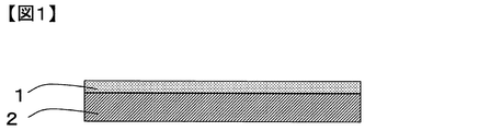
- FIG. 1 shows a schematic view (side view) of a laminated film according to an embodiment of the present invention.
- seat for solar cell modules which concerns on one Embodiment of this invention is shown.
- FIG. 1 shows a schematic diagram (side view) of a solar cell module according to one embodiment of the present invention.
- the laminated film of the present invention has an A layer and a B layer, and when the A layer has a polyvinyl alcohol-based resin as a main component and the polyvinyl alcohol-based resin in the layer is 100 parts by mass,
- the layered compound contains 2 parts by mass or more and 45 parts by mass or less, the content of the polyvinyl alcohol-based resin in the B layer is smaller than the content of the polyvinyl alcohol-based resin in the A layer, and the content of the polyvinyl alcohol-based resin in the A layer is
- the average degree of polymerization is 250 or more and 1,600 or less, and the degree of orientation of the A layer measured by In-Plane XRD is 5% or more.
- FIG. 1 is a schematic view (side view) of a laminated film according to an embodiment of the present invention.
- the layer A contains a polyvinyl alcohol-based resin as a main component.
- the “main component” refers to a resin component contained in an amount of more than 50% by mass when the entire resin component in the layer is taken as 100% by mass.
- the main components can be similarly interpreted.
- the polyvinyl alcohol-based resin in the A layer may be one kind or plural kinds, and the content of the polyvinyl alcohol-based resin in the latter case is calculated by adding all the polyvinyl alcohol-based resins.
- Polyvinyl alcohol-based resin has a high effect of blocking water vapor because of high cohesion. Further, since the polyvinyl alcohol-based resin has a high affinity for an inorganic layered compound described later, the dispersibility of the inorganic layered compound is good. By dispersing the inorganic layered compound in the polyvinyl alcohol-based resin, it is possible to lengthen the permeation path when water vapor passes through the layer A. For these reasons, when the layer A has a polyvinyl alcohol-based resin as a main component, the water vapor barrier property of the laminated film is improved.
- the effect of dispersing the inorganic layered compound to lengthen the permeation path when water vapor passes through the A layer may be referred to as a maze effect.
- a polyvinyl alcohol-based resin is a repeating unit represented by the chemical formula 1 in a polymer chain (hereinafter, sometimes referred to as a vinyl alcohol unit) when the total of repeating units in the polymer chain of the resin is 100 mol%. ) Is more than 50 mol% and 100 mol% or less.
- the polyvinyl alcohol-based resin in the A layer can be appropriately selected within a range that does not impair the effects of the present invention as long as the above requirements are satisfied.
- saponified polyvinyl acetate and vinyl acetate are used. Saponified polymers (specific examples of copolymerization components will be described later), resins having a 1,2-diol structure in the side chain in addition to vinyl alcohol units, and modified products obtained by chemically modifying the hydroxyl groups of these resins It is preferable that the resin is at least one resin selected from the group consisting of:
- the polyvinyl alcohol resin in the layer A may be a saponified polyvinyl acetate having a small number of crosslinking points, a saponified vinyl acetate copolymer, a vinyl alcohol unit, or a side chain. Is preferably one or more resins selected from resins having a 1,2-diol structure.
- the saponification degree of the polyvinyl alcohol-based resin in the A layer is preferably from 80 mol% to 100 mol%, more preferably from 90 mol% to 100 mol%, and more preferably from 98 mol% to 100 mol%, from the viewpoint of water vapor barrier properties. It is more preferred that:
- the degree of saponification refers to the degree of saponification measured according to JIS @ K @ 6726 (1994).
- the polyvinyl alcohol resin in the A layer has a 1,2-diol structure in the side chain in addition to the vinyl alcohol unit.
- Examples of the copolymerization component in the polyvinyl alcohol-based resin include unsaturated carboxylic acids (including salts, esters, amides, and nitriles) and olefins having 2 to 30 carbon atoms (eg, ethylene, propylene, n-butene, isobutene, etc.). ), Vinyl ethers, unsaturated sulfonates and the like.
- Examples of the resin having a 1,2-diol structure in the side chain in addition to the vinyl alcohol unit include saponified copolymers of vinyl acetate and 3,4-diacetoxy-1-butene, and vinyl acetate and vinyl ethylene carbonate.
- Decarboxylated product of a copolymer of vinyl acetate and 2,2-dialkyl-4-vinyl-1,3-dioxolane; deketalized product of a saponified product of a copolymer of vinyl acetate and 2,2-dialkyl-4-vinyl-1,3-dioxolan; Saponified products of copolymers with allyl ether and the like can be mentioned.
- the chemical modifying agent for chemically modifying the hydroxyl group of the resin is not particularly limited as long as the effects of the present invention are not impaired, but from the viewpoint of reducing the decrease in water vapor barrier property under high humidity, aldehyde, acid, epoxy resin, melamine resin It is preferably at least one chemical modifier selected from, isocyanates, organic halides, silane coupling agents, titanium compounds, and metal chelate compounds.
- the chemical modifier is at least one selected from aldehydes, melamine resins, and titanium compounds.
- the average degree of polymerization of the polyvinyl alcohol resin in the layer A is 250 or more and 1600 or less from the viewpoint of achieving both appearance and productivity.
- the appearance of the layer A which may be generated when the coating material as the material for the layer A is applied to the sheet as the material for the layer B described later and the film is stretched, is obtained.
- Deterioration and reduction in water vapor barrier properties can be reduced. That is, even if coating and stretching are performed continuously, a laminated film can be obtained without impairing the appearance and the water vapor barrier property. Therefore, in order to form the A layer, an extra step such as vapor deposition or bonding is provided. Eliminates the need and increases productivity.
- the average polymerization degree of the polyvinyl alcohol-based resin in the A layer is 250 or more, the flexibility of the A layer is increased, so that the damage of the A layer at the time of stretching is reduced, and the accompanying decrease in the water vapor barrier property can be suppressed. it can. Further, from the viewpoint of suppressing the damage of the layer A even at a higher stretching ratio, the average polymerization degree of the polyvinyl alcohol-based resin in the layer A is more preferably 270 or more, and further preferably 300 or more.
- the average polymerization degree of the polyvinyl alcohol-based resin in the A layer is 1,600 or less, the viscosity of the coating material can be suppressed, and the leveling property at the time of coating can be increased. It is possible to suppress unevenness and the accompanying deterioration in appearance.
- the average degree of polymerization of the polyvinyl alcohol-based resin in the layer A is preferably 1,000 or less, more preferably 500 or less, and even more preferably 380 or less.
- the average degree of polymerization of the polyvinyl alcohol-based resin in the A layer is 250 or more and 1,000 or less from the viewpoint of reducing the damage of the A layer during stretching, reducing the thickness unevenness of the A layer, and reducing the deterioration of the appearance of the laminated film.
- the average polymerization degree of the polyvinyl alcohol-based resin in the layer A is determined by extracting the polyvinyl alcohol-based resin from the layer A with hot water and conforming to JIS @ K 6726 (1994).
- the measurement is performed after a chemical reaction is performed until all the side chains become hydroxyl groups by performing saponification or reverse aldol reaction.
- confirmation as to whether or not the compound is a modified compound can be performed by NMR (nuclear magnetic resonance spectroscopy).
- the average polymerization degree can be measured by the above method without separating the respective components.
- the melting point of the layer A is preferably 210 ° C. or less.
- the appearance of the layer A which may be generated when the coating material as the material for the layer A is applied to the sheet as the material for the layer B described later and the film is stretched, is obtained. Deterioration and reduction in water vapor barrier properties can be reduced. Specifically, even if a small damaged portion occurs in the stretching step, the layer A is melted due to the low melting point, and the damaged portion can be filled.
- the melting point of the layer A is more preferably 200 ° C. or lower, further preferably 185 ° C. or lower, and particularly preferably 180 ° C. or lower.
- the melting point of the layer A is preferably 100 ° C. or higher, more preferably 150 ° C. or higher. That is, the melting point of the A layer is preferably from 100 ° C. to 210 ° C., more preferably from 150 ° C. to 200 ° C., from the viewpoint of reducing the deterioration of appearance and the decrease in water vapor barrier property, and from the viewpoint of heat resistance.
- the temperature is more preferably from 150 ° C to 185 ° C, particularly preferably from 150 ° C to 180 ° C.
- the melting point can be measured using a differential scanning calorimeter (DSC). Specifically, it refers to the highest temperature among the peak endothermic peaks when the temperature is increased from 90 ° C. to 250 ° C. at a rate of 10 ° C./min under a nitrogen atmosphere.
- DSC differential scanning calorimeter
- an input compensation type differential scanning calorimeter DSC-7 manufactured by Perkin Elmer Co., Ltd. can be used.
- the inorganic layered compound has 2 parts by mass or more and 45 parts by mass. It is important to include the following parts.
- the layer A contains 2 parts by mass or more of the inorganic layered compound when the polyvinyl alcohol resin in the layer is 100 parts by mass, the water vapor barrier property of the layer A is improved by a so-called maze effect.
- the layer A more preferably contains the inorganic layered compound in an amount of 5 parts by mass or more, more preferably 8 parts by mass or more.
- a layer when the polyvinyl alcohol-based resin in the layer is 100 parts by mass, by including the inorganic layered compound at 45 parts by mass or less, the elongation of the A layer during stretching can be maintained to a sufficient degree, Breakage of layer A during stretching can be reduced.
- the viscosity of the coating material which is a raw material of the layer A, can be suppressed and the leveling property at the time of coating can be increased, it is possible to reduce the thickness unevenness of the layer A and the deterioration of the appearance of the laminated film associated therewith. it can.
- the layer A contains the inorganic layered compound at 22 parts by mass or less when the polyvinyl alcohol-based resin in the layer is 100 parts by mass. More preferably, the content is more preferably 12 parts by mass or less.
- the layer A may contain 5 to 22 parts by mass of the inorganic layered compound when the polyvinyl alcohol-based resin in the layer is 100 parts by mass. More preferably, it is more preferably not less than 8 parts by mass and not more than 12 parts by mass.
- the term “inorganic layered compound” refers to an inorganic compound in which unit crystal layers are stacked on each other to form a layered structure.
- the layered structure refers to a structure in which planes in which atoms are strongly bonded by covalent bonds or the like and densely arranged are stacked by a weak bonding force such as van der Waals. From the viewpoint of coating properties and water vapor barrier properties, it is preferable to use a clay mineral among inorganic layered compounds.
- the inorganic layered compound may be used alone or in combination of two or more. When a mixture of a plurality of types is used, the content is calculated by adding all the inorganic layered compounds.
- Clay minerals generally have a (i) type having a two-layer structure having an octahedral layer having a central metal such as aluminum or magnesium on the top of a tetrahedral layer of silica; and (ii) a tetrahedral layer of silica comprising aluminum. It is classified into a type having a three-layer structure in which an octahedral layer having a central metal such as magnesium or magnesium is sandwiched from both sides.
- Examples of the clay mineral of the two-layer structure type (i) include a kaolinite group-serpentine group clay mineral and the like.
- Examples of the clay mineral of the three-layer structure type (ii) include clay minerals such as a talc-pyrophyllite group, a smectite group, a vermiculite group, a mica group, a brittle mica group, and a chlorite group depending on the number of interlayer cations. .
- Examples of the kaolinite-serpentine family include kaolinite, dickite, nacrite, halloysite, antigolite, chrysotile, lizardite, amesite, barcherin, clonsteadite, nepoite, keliite, frayponite, brindriaite, and the like. No.
- talc-pyrophyllite family examples include talc, willemsite, kerolite, pimelite, pyrophyllite, ferripyrophyllite and the like.
- Specific examples of the smectite group include montmorillonite, beidellite, nontronite, saponite, sauconite, stevensite, hectorite, volconcolite, and swinholite.
- Specific examples of the vermiculite family include trioctahedral vermiculite, and dioctahedral vermiculite.
- the mica group include tetrasilyl mica, sodium teniolite, muscovite, phlogopite, biotite, iron mica, yeast knight, siderophyllite tetraferri iron mica, scale mica, polylithionite, and celadonite.
- Specific examples of the brittle mica family include zansophyllite, clintonite, bite mica, anandite, pearl mica, margaylat, and the like.
- Specific examples of the chlorite family include clinochlore, chamosite, pennantite, nimite, crizbasite, coucheite, sudoite and the like.
- those obtained by treating these clay minerals with organic matter, such as ion exchange, to improve the dispersibility, etc. may also be used as inorganic layered compounds.
- organic matter such as ion exchange, to improve the dispersibility, etc.
- organically modified clay minerals may also be used as inorganic layered compounds.
- organic substance for treating the clay mineral known quaternary ammonium salts such as dimethyl distearyl ammonium salt and trimethyl stearyl ammonium salt, phosphonium salts, imidazolium salts and the like can be used.
- the clay mineral is not particularly limited as long as the effects of the present invention are not impaired, and may be arbitrarily selected. Any one of the smectite group, vermiculite group, and mica group, which is a clay mineral having a three-layer structure (ii), It is preferable to use at least one kind of clay mineral that corresponds to the group (C), and it is more preferable to use at least one kind of clay mineral that corresponds to the smectite group or the mica group.
- the smectite group it is preferable to use at least one of montmorillonite, beidellite, nontronite, saponite, sauconite, stevensite, and hectorite, and in particular, use montmorillonite from the viewpoint of swelling to a liquid medium and cleavage. Is more preferred.
- the mica group swellable mica is preferably used from the viewpoint of cleavage.
- the aspect ratio of the inorganic layered compound in the laminated film of the present invention is preferably 80 or more and 2,500 or less from the viewpoint of achieving both the water vapor barrier property and the appearance.
- the aspect ratio of the inorganic layered compound is 80 or more, the maze effect in the A layer is improved, so that the water vapor barrier property is improved.
- the aspect ratio is more preferably 300 or more, and further preferably 2,100 or more.
- the aspect ratio of the inorganic layered compound is 2,500 or less, it is possible to suppress the viscosity of the coating material from being increased, and to improve the leveling property during coating. Therefore, it is possible to reduce the thickness unevenness of the A layer and the resulting deterioration in appearance. That is, the aspect ratio of the inorganic layered compound is more preferably 300 or more and 2,500 or less, and further preferably 2,100 or more and 2,500 or less, from the viewpoint of achieving both the water vapor barrier property and the appearance of the laminated film.
- the average particle diameter L of the inorganic layered compound is a particle diameter (volume-based median diameter) determined by a diffraction scattering method in a liquid medium. That is, L can be obtained by calculating a particle size distribution appropriate for the diffraction and scattering patterns from the diffraction and scattering patterns obtained when light is passed through the dispersion liquid of the inorganic layered compound by Mie scattering theory or the like. it can.
- the unit thickness a (nm) of the inorganic layered compound and the average particle size L (nm) of the inorganic layered compound will be specifically described.
- an inorganic layered compound as a raw material is available, it is measured using this.
- the obtained inorganic layered compound is an aqueous dispersion, the measurement is performed after pulverization after drying.
- the inorganic layered compound as a raw material is not available, it can be measured by the following method.
- the layer A is scraped to obtain a sample of the layer A of about 1 to 10 g, and then the sample of the layer A is heated to an ambient temperature of 600 ° C. in a nitrogen atmosphere and is held for at least 30 minutes.
- the sample of the layer A is heated to an ambient temperature of 600 ° C. in an oxygen atmosphere and kept for at least 30 minutes.
- the residue obtained after allowing to cool to 25 ° C. is used as an inorganic layered compound sample for measuring unit thickness a (nm).
- pure water is added so that the concentration of the residue becomes 0.1% by mass, and the liquid stirred with a stirring rod is used as a sample for measuring the average particle size L of the inorganic layered compound.
- L (nm) can be obtained as a median diameter obtained by measuring a volume-based particle size distribution.
- a volume-based particle size distribution measuring device for example, a particle size distribution measuring device “Microtrack” (registered trademark) MT3300II manufactured by Microtrac Bell Co., Ltd. can be used.
- the solvent is water (refractive index: 1.333), and the refractive index of the particles is 1.56.
- the laminated film of the present invention has an average degree of polymerization of the polyvinyl alcohol-based resin of 250 or more and 1,000 or less, and when the content of the polyvinyl alcohol-based resin is 100 parts by mass, the content of the inorganic layered compound is b. (Parts by mass), and when the melting point of the layer A is T (° C.), it is preferable to satisfy 2 ⁇ b ⁇ 83 ⁇ 0.36T.
- the melting point T (° C.) of the layer A and the content b (parts by mass) of the inorganic layered compound are set to satisfy 2 ⁇ b ⁇ 83 ⁇ 0.36T.
- production can be performed at a high stretching ratio. Is also preferable from the viewpoint of productivity because damage to layer A during production can be reduced.
- the inorganic layered compound is more likely to be arranged in parallel to the substrate surface, and the water vapor barrier property is also increased.
- the orientation degree of the layer A measured by In-Plane XRD (hereinafter, may be simply referred to as the orientation degree of the layer A) is 5% or more. It is.
- the orientation degree of the A layer is 5% or more, the inorganic layered compound is easily arranged in parallel with the film surface, and the water vapor barrier property is improved.
- the orientation degree of the layer A is more preferably 30% or more, and further preferably 50% or more.
- the upper limit of the orientation of the layer A is preferably as large as possible, and there is no particular upper limit, but theoretically the upper limit is 100%.
- the method for setting the degree of orientation of the layer A to 5% or more or the above preferable range is not particularly limited as long as the effects of the present invention are not impaired, and examples thereof include a method of adjusting the stretching ratio of the laminated film. Specifically, the degree of orientation of the layer A can be increased by increasing the stretching ratio.
- the method of setting the orientation degree of the layer A to 5% or more can be appropriately selected within a range that does not impair the effects of the present invention.
- the degree of orientation of the layer A is determined by X-ray diffraction analysis using the laminated film as a measurement sample by the In-Plane method.
- the In-Plane method is a type of thin-film X-ray diffraction that can measure X-ray diffraction of a layer or the like formed on a substrate, among X-ray diffraction analysis techniques.
- Thin-film X-ray diffraction is classified into an In-Plane method and an Out-Of-Plane method.
- the X-ray incident angle at the time of measurement is in the range of 5.00 ° to 90.00 ° in the Out-Of-Plane method, whereas it is generally in the range of 0.20 ° to 0.50 ° in the In-Plane method. Range.
- the In-Plane method has a smaller X-ray incident angle than the Out-Of-Plane method, and therefore has a shallower penetration depth of X-rays. Therefore, X-ray diffraction analysis of the surface layer of the sample to be measured can be performed by X-ray diffraction analysis using the In-Plane method (In-Plane XRD).
- the X-ray incidence angle is 0.25 °.
- the measurement of the degree of orientation of the layer A by ⁇ In-Plane ⁇ XRD can be performed using a thin film X-ray diffractometer according to the following procedure and conditions. Measurement conditions were as follows: Cu source used (output: 45 kV, 200 mA); Scan condition: 0.05 ° / step, 0.1 ° / min in the range of 3 to 50 °, optical system used: parallel optical system, measuring method: 2 ⁇ (diffraction angle) scan (X-ray incident angle 0.25 °) can be achieved.
- the above measurement conditions are set values in a thin film X-ray diffractometer.
- the thin-film X-ray diffractometer a known device can be used, and an example thereof is Rigaku's SmartLab.
- the difference spectrum having the largest absolute value (peak height or valley depth) between 2 ⁇ 17 to 23 °, the tip of the peak or valley Is specified.
- the diffraction angle is fixed at 2 ⁇ 0.5 ⁇ 0.5 °, and the measurement is performed by rotating in the plane of the sample.
- the uncorrected azimuth distribution curve refers to an azimuth distribution curve before the background correction is performed.
- the measurement is performed under the same conditions except that the measurement sample is removed from the optical axis of the X-ray, and the background of the azimuth distribution curve is calculated.
- the background is removed from the uncorrected azimuth distribution curve, and the azimuth distribution curve after the background correction (hereinafter, also simply referred to as “azimuth distribution curve”). Get.
- the thickness of the layer A is preferably 0.05 ⁇ m or more and 10.00 ⁇ m or less from the viewpoints of water vapor barrier properties and productivity.
- the thickness of the layer A is 0.05 ⁇ m or more, the layer A can sufficiently block water vapor.
- the thickness of the layer A is more preferably equal to or greater than 0.20 ⁇ m, and still more preferably equal to or greater than 0.50 ⁇ m.
- the A layer when the thickness of the A layer is 10.00 ⁇ m or less, the A layer can be formed by coating, and an additional step such as a bonding step can be omitted. Also, when the A layer is formed by coating, energy required for drying the coating agent can be omitted, so that the productivity is excellent.
- the thickness of the layer A is more preferably 5.00 ⁇ m or less, and further preferably 2.00 ⁇ m or less. In other words, the thickness of the layer A is more preferably 0.20 ⁇ m or more and 5.00 ⁇ m or less, and further preferably 0.50 ⁇ m or more and 2.00 ⁇ m or less, from the viewpoint of achieving both the water vapor barrier property and the productivity.
- the thickness of the layer A is obtained by obtaining a cross section in the thickness direction including the layer A by a known cross-sectioning method such as an ion milling method, and using an SEM (scanning electron microscope such as a field emission scanning electron microscope (FE) manufactured by Hitachi, Ltd.). -SEM) S-800).
- the thickness direction refers to a direction perpendicular to the film surface.
- the laminated film of the present invention has a B layer from the viewpoint of improving the handleability of the laminated film.
- the layer B is made of polyester resin, olefin resin, polystyrene resin, polyacrylonitrile resin, acrylonitrile-styrene copolymer resin, acrylonitrile-butadiene-styrene copolymer from the viewpoints of handling properties, heat resistance of the laminated film, and productivity by stretching.
- the component be a main component.
- the layer B mainly contains a component selected from polyethylene terephthalate and polypropylene, and is stretched at a stretching temperature suitable for obtaining the layer A, whereby a laminated film having the layer A and the layer B can be easily formed. It is more preferable in that it can be obtained.
- the content of the polyvinyl alcohol-based resin in the layer B is smaller than the content of the polyvinyl alcohol-based resin in the layer A.
- “the content of the polyvinyl alcohol-based resin in the B layer is smaller than the content of the polyvinyl alcohol-based resin in the A layer” means that the entire resin component in the B layer is calculated as 100% by mass. Means that the amount of the polyvinyl alcohol-based resin (% by mass) is lower than the amount (% by mass) of the polyvinyl alcohol-based resin in the A layer calculated by assuming that the entire resin component in the A layer is 100% by mass.
- the stiffness of a polyvinyl alcohol-based resin as a film is lower than that of a resin suitable as a main component of the B layer. Therefore, by adopting such an embodiment, the stiffness of the layer B is sufficiently maintained, and the handling property of the entire laminated film is improved.
- the layer A is mainly composed of a polyvinyl alcohol-based resin, but the layer B is not particularly limited whether or not it contains a polyvinyl alcohol-based resin.
- the polyvinyl alcohol-based resin in the B layer may be the same component as or different from that of the A layer.
- the laminated film of the present invention has a water vapor transmission rate per 1 ⁇ m of the layer A of 5.0 g / m 2 / day or less from the viewpoint of securing a water vapor barrier property to a degree suitable for solar cell use and packaging material use. Is preferable, and it is more preferable that it is 3.0 g / m ⁇ 2 > / day or less.
- the water vapor transmission rate per 1 ⁇ m of the layer A refers to the water vapor transmission rate per 1 ⁇ m of the layer A measured without a wet heat treatment by a method described later.
- the laminated film can easily have a water vapor barrier property that can be suitably used for solar cell applications, packaging material applications, and the like.
- the smaller the water vapor transmission rate per 1 ⁇ m of the layer A the more preferable. It is not particularly limited as long as the effect of the present invention is not impaired, but is 0.02 g / m 2 / day from the viewpoint of detection limit.
- Means for setting the water vapor transmission rate per 1 ⁇ m of the A layer to 5.0 g / m 2 / day or less or the above preferable range is not particularly limited as long as the effects of the present invention are not impaired. And a method for producing the same. At this time, in order to reduce breakage of the layer A during stretching, the stretching ratio is reduced or the stretching start temperature is increased as far as productivity or the like allows, thereby increasing the water vapor transmission rate per 1 ⁇ m of the layer A. be able to.
- the water vapor transmission rate per 1 ⁇ m of the layer A is a value measured at a temperature of 40 ° C. and a humidity of 90% RH.
- the water vapor transmission rate per 1 ⁇ m of the layer A can be measured under the conditions of a temperature of 40 ° C. and a humidity of 90% RH, for example, with a water vapor transmission rate measuring apparatus (model name “Permatran” (registered trademark) W3 / 31) can be measured according to the method B (infrared sensor method) described in JIS K7129 (2000).
- the specific measurement procedure when the same method is used is as follows. First, a measurement sample is set so that at least the layer A is on the low humidity chamber side, and the water vapor transmission rate (A) (g / m 2 / day) is measured. Next, the water vapor transmission rate is measured in the same manner using the laminate film from which the layer A has been removed by a known method, and the result is taken as the water vapor transmission rate (B) of the layer B (g / m 2 / day).
- the water vapor transmission rate (C) (g / m 2 / day) of the layer A is determined by the following equation (3), which is converted by the following equation (4), and the water vapor transmission rate per 1 ⁇ m of the layer A ( D) (g / m 2 / day) is determined.
- the lower detection limit of the water vapor transmission rate is set to 0.02 g / m 2 / day, and t in the formula (4) means the thickness ( ⁇ m) of the A layer.
- the water vapor transmission rate of the base film is measured in place of the film obtained by removing the layer A from the laminated film. May be used as the water vapor transmission rate.
- polyvinyl alcohol (average degree of polymerization: 1,500) powder having a saponification degree of 98 mol% or more is added to water, mixed with a stirring bar, heated to 95 ° C., and stirred for 10 minutes to obtain polyvinyl alcohol. Is dissolved in water. Thereafter, while maintaining the temperature at 95 ° C., an Na-type montmorillonite having an aspect ratio of 500 is added, the mixture is stirred for 10 minutes, and then cooled to room temperature to prepare an aqueous coating composition.
- a known base film for example, a polyethylene terephthalate film is cut into an arbitrary size such as A4 size, and after corona treatment, the above-mentioned water-based coating agent is applied by a known coating method, for example, metabar coating, and is heated at 100 ° C. And then cooled to room temperature. Subsequently, the dried film is gripped with a clip capable of gripping the side of the film, and heated in an oven heated to a temperature equal to or higher than the glass transition temperature of the polyvinyl alcohol-based resin (in this case, 85 ° C. or higher).
- the laminated film can be obtained by extending the clip interval and stretching the film, and then cooling it to room temperature.
- the steps after the application of the water-based coating agent can be performed together with the formation of the base film.
- An example of the procedure in that case is as follows. First, a raw material resin (for example, polyethylene terephthalate) for a base film is melted and formed into a sheet by a casting method or the like. Next, the surface of the obtained sheet is subjected to a corona treatment, and the above-mentioned aqueous coating agent is applied by a known coating method and dried. Thereafter, the temperature of the film is raised to a temperature equal to or higher than the glass transition temperature of the polyvinyl alcohol-based resin, and the film is stretched by a known stretching method, whereby a laminated film can be obtained.
- a raw material resin for example, polyethylene terephthalate
- the above-mentioned aqueous coating agent is applied by a known coating method and dried. Thereafter, the temperature of the film is raised to a temperature equal to or higher than the glass transition temperature of the polyvinyl
- the timing of stretching and coating can be appropriately selected within a range that does not impair the effects of the present invention.
- the film is stretched in a running direction of the film (hereinafter, sometimes referred to as a flow direction) before coating, and is stretched in a direction orthogonal to the flow direction in the plane (hereinafter, sometimes referred to as a width direction) after coating.
- a running direction of the film hereinafter, sometimes referred to as a flow direction
- a width direction a direction orthogonal to the flow direction in the plane
- it may be stretched in the width direction before coating, and may be stretched in the flow direction after coating.
- biaxial stretching may be performed sequentially or simultaneously in the flow direction and the width direction.
- the stretching ratio can be appropriately set, regardless of the stretching method, as long as the effect of the present invention is not impaired.
- the stretching ratio is 1.5 times or more and 4.0 times or less from the viewpoint of setting the degree of orientation of the A layer to 5% or more and reducing the reduction of the water vapor barrier.
- the A layer is likely to be damaged due to stretching. Then, it is more preferable to adjust the stretching ratio within the range of 1.5 times or more and 4.0 times or less. That is, when lowering the average degree of polymerization of the polyvinyl alcohol-based resin or when increasing the content of the inorganic layered compound, it is more preferable to lower the stretching ratio within the range of 1.5 times or more and 4.0 times or less.
- the sheet for a solar cell module of the present invention contains the laminated film of the present invention.
- “including the laminated film of the present invention” means that, in addition to the aspect of the laminated film itself of the present invention, also includes an aspect in which one or more different layers are located on at least one surface of the film of the present invention. means.
- the laminated film of the present invention has excellent water vapor barrier properties as described above, and thus can be suitably used as a solar cell module sheet such as a solar cell module sealing material and a solar cell module backsheet.
- a solar cell module sheet such as a solar cell module sealing material and a solar cell module backsheet.
- intrusion of gas, particularly water vapor, into the solar cell module can be suppressed, leading to improvement in reliability and durability of the solar cell module.
- the layer A can be stretched together with the stretching process of the base material, it is more preferable to use the backsheet for a solar cell module.
- the solar cell module sheet may be a laminated film of the present invention laminated with a known functional film with an adhesive or the like, or a laminated film of the present invention provided with a functional coating.
- FIG. 2 shows a schematic diagram (side view) of a solar cell module sheet according to one embodiment of the present invention.
- the solar cell module sheet 5 shown in FIG. 2 includes a fluorine film 4, an adhesive layer 3, an A layer 1, a B layer 2, an adhesive layer 3, and a fluorine film 4 in this order. Corresponds to the laminated film of the present invention.
- packaging material and its manufacturing method It is important that the packaging material of the present invention contains the laminated film of the present invention.
- “including the laminated film of the present invention” means that, in addition to the aspect of the laminated film itself of the present invention, also includes an aspect in which one or more different layers are located on at least one surface of the film of the present invention. means.
- the laminated film of the present invention has excellent water vapor barrier properties as described above, for example, packaging materials for foods, packaging materials for general miscellaneous goods such as ink tanks and insect repellents, and packaging materials for industrial materials such as semiconductors. It can be suitably used as a material.
- the use as a packaging material for foods leads to an extension of the expiration date by suppressing the invasion of water vapor into foods.
- it is possible to suppress the deterioration of the active ingredient and contribute to stabilization of quality.
- the packaging material may be one using the laminated film of the present invention as it is, but may be one obtained by laminating the laminated film of the present invention and a known functional film used as a heat-sealing material to an adhesive or the like.
- the coating film and the vapor deposition may be applied to the laminated film of the above.
- the packaging material of the present invention can be used after being shaped into a specific shape by molding, or can be used in combination with other packaging materials.
- the layer A is located closer to the contents than the layer B in that the invasion of gas such as water vapor or oxygen from the outside can be suppressed.
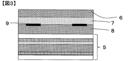
- FIG. 3 shows an example of a schematic diagram of a solar cell module according to one embodiment of the present invention.
- the solar cell module shown in FIG. 3 includes, in order from the light receiving surface side, a light receiving surface protection base material 6, a light receiving surface side sealing material 7, a solar cell 9, a back surface sealing material 8, and a solar cell module sheet 5. .
- the light receiving surface side sealing material 7 and the back surface side sealing material 8 may be the same or different as long as the effects of the present invention are not impaired.
- the method for producing a solar cell module of the present invention includes, for example, a method having a step of heating and pressing a laminate including the solar cell module sheet of the present invention under reduced pressure.
- a method having a step of heating and pressing a laminate including the solar cell module sheet of the present invention under reduced pressure As a specific example of such a method, a light-receiving surface protection base material, a light-receiving surface side sealing material, a solar cell, a back surface sealing material, and a sheet for a solar cell module of the present invention are stacked in this order and heated under reduced pressure.
- a method having a step of pressure bonding may be used.
- a known laminator can be used as the laminator used in the step of laminating each member and heating and pressing under reduced pressure, and a laminator that can be heated from the light-receiving surface protection base material side, or a light-receiving surface protection base material side And a laminator that can be heated from both sides of the solar cell module sheet side. It is also preferable to adjust the crosslinking rate of the light-receiving surface side sealing material by heating in a known curing furnace after lamination.
- the laminated film was cut in parallel with the thickness direction using a microtome to obtain a section sample.
- a cross section (cross section in the thickness direction) of the section sample was processed using an argon gas by an ion milling device IM4000Plus manufactured by Hitachi High-Technologies Corporation to obtain a cross section.
- IM4000Plus manufactured by Hitachi High-Technologies Corporation
- FE-SEM field emission scanning electron microscope
- the background is removed from the uncorrected azimuth distribution curve to obtain the azimuth distribution after the background correction.
- a curve was obtained.
- the degree of orientation of the layer A was determined from the obtained azimuth distribution curve according to the following equation (2).
- W in the formula (2) is the total value obtained when the integrated value of the entire peak of the azimuth distribution curve is 100% and the total width of the peak at which the integrated value is 50% is obtained for all the orientation peaks. Is the sum of the values of
- Melting point of layer A About 2 mg of the A layer was sampled and used as a measurement sample, which was measured using an input-compensated differential scanning calorimeter DSC-7 manufactured by PerkinElmer. Specifically, the temperature of the measurement sample was increased from 90 ° C. to 250 ° C. at a rate of 10 ° C./min in a nitrogen atmosphere, and the highest temperature among the peaks of the obtained endothermic peaks was determined as the melting point of the A layer. (° C.).
- the water vapor transmission rate of a substrate not coated with a coating agent during the production of the laminated film (base film) was similarly measured, and the water vapor transmission rate (B) (g / m 2 / day).
- the water vapor transmission rate (C) (g / m 2 / day) of the layer A is determined by the following equation (3), and is converted by the following equation (4) to obtain the water vapor transmission rate (D) (g / m 2 / day) was determined.
- the lower detection limit of the water vapor transmission rate is set to 0.02 g / m 2 / day, and t in the formula (4) means the thickness ( ⁇ m) of the A layer.
- L (nm) was obtained by measuring the volume-based particle size distribution using a particle size distribution analyzer “Microtrack” (registered trademark) MT3300II manufactured by Microtrac Bell Co., Ltd., and the obtained median diameter.
- the solvent was water (refractive index: 1.333), and the refractive index of the particles was 1.56.
- Unstretched polyester film 1 Unstretched polyester film 15-103 manufactured by Mineron Kasei Kogyo Co., Ltd.
- Unstretched polypropylene film 2 Unstretched polypropylene film “CP” RXC-22 manufactured by Mitsui Chemicals Tosello Co., Ltd., thickness 60 ⁇ m.
- Polyvinyl alcohol-based resin 1 (PVA1): Completely saponified polyvinyl alcohol "GOHSENOL” (registered trademark) N-300 (manufactured by Mitsubishi Chemical Corporation) (Saponification degree: 98.0 to 99.0 mol%, average polymerization degree: 1,500)
- Polyvinyl alcohol-based resin 2 (PVA2): Fuji Film Wako Pure Chemical Industries, Ltd., completely saponified polyvinyl alcohol 1,000 (Wako first grade, saponification degree 96 mol% or more, average polymerization degree 1,000)
- Polyvinyl alcohol resin 3 (PVA3): Fully saponified polyvinyl alcohol 500 manufactured by Fuji Film Wako Pure Chemical Industries, Ltd.
- Polyvinyl alcohol-based resin 4 Partially saponified polyvinyl alcohol "GOHSENOL” (registered trademark) GM-14L manufactured by Mitsubishi Chemical Corporation (degree of saponification: 88 mol%, average degree of polymerization: 1,200)
- Polyvinyl alcohol resin 5 PVA5: "Nichigo G Polymer” (registered trademark) OKS-1109 manufactured by Mitsubishi Chemical Corporation (saponification degree: 98.0 to 99.0 mol%, average polymerization degree: 1,200)
- Polyvinyl alcohol-based resin 6 (PVA6): Fully saponified polyvinyl alcohol "Kuraray Poval” (registered trademark) PVA120 (manufactured by Kuraray Co., Ltd.) (Saponification degree: 98.0 to 99.0 mol%, average polymerization degree: 2,000)
- Polyvinyl alcohol-based resin 7 PVA7
- Polyvinyl alcohol-based resin 8 (PVA8): “Nichigo G Polymer” (registered trademark) AZF8035W (manufactured by Mitsubishi Chemical Corporation) (degree of saponification 98.0 mol% or more, average degree of polymerization 300)
- Polyvinyl alcohol-based resin 9 (PVA9): “Nichigo G Polymer” (registered trademark) OKS-1011 manufactured by Mitsubishi Chemical Corporation (saponification degree 98.0 mol% or more, average polymerization degree 300)
- Polyvinyl alcohol-based resin 10 (PVA10): “Nichigo G-Polymer” (registered trademark) OKS-8118 (manufactured by Mitsubishi Chemical Corporation) (Saponification degree 99.0 mol% or more, average polymerization degree 300)
- Polyvinyl alcohol-based resin 11 (PVA11): PVA7 and PVA8 are blended and the average degree of polymerization is adjusted to 270.
- Polyvinyl alcohol-based resin 12 (PVA12): What blended PVA7 and PVA8 and adjusted the average degree of polymerization to 250 Polyvinyl alcohol-based resin 13 (PVA13): “Nichigo G Polymer” (registered trademark) OKS-8039 manufactured by Mitsubishi Chemical Corporation (saponification degree 98.0 mol% or more, average polymerization degree 600)
- Polyvinyl alcohol-based resin 14 (PVA14): “Nichigo G Polymer” (registered trademark) OKS-1028 manufactured by Mitsubishi Chemical Corporation (saponification degree 98.0 mol% or more, average polymerization degree 600)
- Polyvinyl alcohol-based resin 15 (PVA15): “Nichigo G Polymer” (registered trademark) BVE-8049Q (manufactured by Mitsubishi Chemical Corporation) (Saponification degree: 99.0 mol% or more, average polymerization degree: 450)
- Polyvinyl alcohol-based resin 16 (PVA16): “Nichigo
- PVA5, PVA8 to 10 and PVA13 to 16 are polyvinyl alcohol-based resins having a 1,2-diol structure in a side chain in addition to a vinyl alcohol unit.
- Inorganic layered compound 1 Refined bentonite "Kunipia” (registered trademark) F (aspect ratio 500) manufactured by Kunimine Industries Co., Ltd.
- Inorganic layered compound 2 Hojun's refined bentonite "BEN-GEL” (registered trademark) HV (aspect ratio 295)
- Inorganic layered compound 3 A swellable synthetic mica aqueous dispersion "Somasif" (registered trademark) MEB-3 (8% by mass aqueous dispersion, aspect ratio 2,400) manufactured by Katakura Corp. Agri.
- Example 1 18 g of the polyvinyl alcohol-based resin 1 was added to 230 g of ion-exchanged water, and immediately after stirring, the liquid temperature was raised to 90 ° C. After the temperature was raised, a shaft generator S25D-14G-KS was attached to an “Ultra Turrax” (registered trademark) homogenizer manufactured by IKA, and the mixture was stirred at 17,000 rpm for 10 minutes. Thereafter, 2 g of the inorganic layered compound 1 was charged, the mixture was stirred at 90 ° C. and 17,000 rpm for 10 minutes, and cooled to room temperature to obtain a coating agent.
- a shaft generator S25D-14G-KS was attached to an “Ultra Turrax” (registered trademark) homogenizer manufactured by IKA, and the mixture was stirred at 17,000 rpm for 10 minutes.
- 2 g of the inorganic layered compound 1 was charged, the mixture was stirred at 90 ° C. and 17,000 rpm for 10 minutes, and cooled
- the unstretched polyester film 1 was subjected to corona treatment using a corona surface modification evaluation device (TEC-4AX) manufactured by Kasuga Electric Co., Ltd. at a gap distance of 1 mm, an output of 100 W, and an electrode moving speed of 6 m / min.
- TEC-4AX corona surface modification evaluation device
- the above-mentioned coating agent is applied to the corona-treated surface at a coating speed of 10 m / min by using Metabar # 15 on the unstretched polyester film 1 that has been subjected to the corona treatment, and heated in an oven at an ambient temperature of 100 ° C. for 5 minutes. Dry and then remove from oven and cool to room temperature. Then, using a biaxial stretching device (model 16A1) manufactured by Imoto Seisakusho, the film was stretched at a stretching temperature of 100 ° C. at a stretching ratio of 1.5 times in a free-width uniaxial stretching mode to obtain a laminated film. In addition, a base film having a thickness of 200 ⁇ m was obtained in the same manner except that the coating material was not applied. Thereafter, each item was evaluated for the obtained laminated film. Table 1 shows the evaluation results.
- Examples 2 to 54, Comparative Examples 1 to 8 As shown in Tables 1 to 8, a laminated film was prepared in the same manner as in Example 1 except that the composition of the coating agent, the stretching ratio, and the coating speed when obtaining the laminated film were changed, and each item was evaluated. . If streaks occur at the time of coating at 10 m / min and the appearance becomes poor, the coating speed is reduced to 5 m / min, 3 m / min, and 0.3 m / min in order to improve the appearance. Coating was performed at the highest speed among the speeds to produce a laminated film. The evaluation results are shown in Tables 1 to 8.
- the stretching ratio at the time of manufacturing the base film was the same as that at the time of manufacturing the laminated film, and the thickness of the base film at a stretching ratio of 2.0 was 150 ⁇ m, and that of the base film at a stretching ratio of 3.0.
- the thickness was 100 ⁇ m.
- Example 55 A laminated film was produced in the same manner as in Example 33 except that the unstretched polypropylene film 2 was used in place of the unstretched polyester film 1 and the stretching temperature for obtaining the laminated film was changed to 150 ° C., and evaluation of each item was performed. Was done. Table 7 shows the evaluation results. The stretching ratio and the stretching temperature during the production of the base film were the same as those during the production of the laminated film, and the thickness of the base film was 20 ⁇ m.
- Example 9 A laminated film was produced in the same manner as in Example 10 except that stretching was not performed, and each item was evaluated. Table 8 shows the evaluation results. Further, since stretching was not performed, the time required to obtain a laminated film having the same area was longer than that in Example 10.
- the amount (% by mass) of the polyvinyl alcohol resin is calculated assuming that the entire resin component in the function is 100% by mass, and the amount (parts by mass) of the inorganic layered compound is based on 100 parts by mass of the polyvinyl alcohol-based resin in the A layer. Calculated.
- the present invention it is possible to provide a laminated film excellent in appearance, productivity, and water vapor barrier property, a sheet for a solar cell module, a packaging material, and a solar cell module excellent in weather resistance.
- Reference Signs List 1 A layer 2 B layer 3 Adhesive layer 4 Fluorine film 5 Sheet for solar cell module 6 Light receiving surface protection base material 7 Light receiving surface side sealing material 8 Back side sealing material 9 Solar cell
Landscapes
- Laminated Bodies (AREA)
- Compositions Of Macromolecular Compounds (AREA)
Abstract
La présente invention vise à fournir un film stratifié qui possède d'excellentes propriétés en termes d'aspect, de productivité et de barrière à la vapeur d'eau. Le film stratifié est caractérisé en ce qu'il comporte une couche A et une couche B, la couche A contenant une résine à base d'alcool polyvinylique en tant que constituant principal, et 2 à 45 parties en masse d'un composé lamellaire inorganique par rapport à 100 parties en masse de la résine à base d'alcool polyvinylique dans la couche ; la teneur de la résine à base d'alcool polyvinylique dans la couche B étant inférieure à la teneur de la résine à base d'alcool polyvinylique dans la couche A ; le degré de polymérisation moyen de la résine à base d'alcool polyvinylique dans la couche A étant de 250 à 1 600 ; et le degré d'orientation de la couche A étant d'au moins 5 % tel que mesuré par XRD dans le plan.
Priority Applications (1)
| Application Number | Priority Date | Filing Date | Title |
|---|---|---|---|
| JP2019534416A JPWO2020004127A1 (ja) | 2018-06-28 | 2019-06-18 | 積層フィルム、太陽電池モジュール用シート、太陽電池モジュール、及び包装材料 |
Applications Claiming Priority (4)
| Application Number | Priority Date | Filing Date | Title |
|---|---|---|---|
| JP2018-122656 | 2018-06-28 | ||
| JP2018122656 | 2018-06-28 | ||
| JP2018235133 | 2018-12-17 | ||
| JP2018-235133 | 2018-12-17 |
Publications (1)
| Publication Number | Publication Date |
|---|---|
| WO2020004127A1 true WO2020004127A1 (fr) | 2020-01-02 |
Family
ID=68986526
Family Applications (1)
| Application Number | Title | Priority Date | Filing Date |
|---|---|---|---|
| PCT/JP2019/024017 Ceased WO2020004127A1 (fr) | 2018-06-28 | 2019-06-18 | Film stratifié, feuille destinée à un module de cellule solaire, module de cellule solaire et matériau d'emballage |
Country Status (3)
| Country | Link |
|---|---|
| JP (1) | JPWO2020004127A1 (fr) |
| TW (1) | TW202005803A (fr) |
| WO (1) | WO2020004127A1 (fr) |
Cited By (1)
| Publication number | Priority date | Publication date | Assignee | Title |
|---|---|---|---|---|
| JP2023018713A (ja) * | 2021-07-28 | 2023-02-09 | 株式会社クラレ | ヒートシール用フィルム及びその分離回収方法 |
Citations (7)
| Publication number | Priority date | Publication date | Assignee | Title |
|---|---|---|---|---|
| JPH09324061A (ja) * | 1996-04-05 | 1997-12-16 | Toray Ind Inc | ガスバリアフィルム |
| JP2001009998A (ja) * | 1999-06-25 | 2001-01-16 | Teijin Ltd | ガスバリア性ポリエステルフィルム |
| JP2006312313A (ja) * | 2005-04-05 | 2006-11-16 | Nippon Synthetic Chem Ind Co Ltd:The | 積層構造体 |
| JP2008284756A (ja) * | 2007-05-16 | 2008-11-27 | Oji Paper Co Ltd | ガスバリアフィルムの製造方法 |
| JP2013248832A (ja) * | 2012-06-01 | 2013-12-12 | Toppan Printing Co Ltd | 積層フィルム及び積層フィルムを用いた太陽電池モジュール |
| JP2014138138A (ja) * | 2013-01-18 | 2014-07-28 | Sumitomo Chemical Co Ltd | 太陽電池パネル用バックシートおよび太陽電池パネル |
| JP2017023981A (ja) * | 2015-07-27 | 2017-02-02 | 住友化学株式会社 | 多層構造体の製造方法 |
-
2019
- 2019-06-18 WO PCT/JP2019/024017 patent/WO2020004127A1/fr not_active Ceased
- 2019-06-18 JP JP2019534416A patent/JPWO2020004127A1/ja active Pending
- 2019-06-25 TW TW108122079A patent/TW202005803A/zh unknown
Patent Citations (7)
| Publication number | Priority date | Publication date | Assignee | Title |
|---|---|---|---|---|
| JPH09324061A (ja) * | 1996-04-05 | 1997-12-16 | Toray Ind Inc | ガスバリアフィルム |
| JP2001009998A (ja) * | 1999-06-25 | 2001-01-16 | Teijin Ltd | ガスバリア性ポリエステルフィルム |
| JP2006312313A (ja) * | 2005-04-05 | 2006-11-16 | Nippon Synthetic Chem Ind Co Ltd:The | 積層構造体 |
| JP2008284756A (ja) * | 2007-05-16 | 2008-11-27 | Oji Paper Co Ltd | ガスバリアフィルムの製造方法 |
| JP2013248832A (ja) * | 2012-06-01 | 2013-12-12 | Toppan Printing Co Ltd | 積層フィルム及び積層フィルムを用いた太陽電池モジュール |
| JP2014138138A (ja) * | 2013-01-18 | 2014-07-28 | Sumitomo Chemical Co Ltd | 太陽電池パネル用バックシートおよび太陽電池パネル |
| JP2017023981A (ja) * | 2015-07-27 | 2017-02-02 | 住友化学株式会社 | 多層構造体の製造方法 |
Cited By (2)
| Publication number | Priority date | Publication date | Assignee | Title |
|---|---|---|---|---|
| JP2023018713A (ja) * | 2021-07-28 | 2023-02-09 | 株式会社クラレ | ヒートシール用フィルム及びその分離回収方法 |
| JP7620513B2 (ja) | 2021-07-28 | 2025-01-23 | 株式会社クラレ | ヒートシール用フィルム及びその分離回収方法 |
Also Published As
| Publication number | Publication date |
|---|---|
| TW202005803A (zh) | 2020-02-01 |
| JPWO2020004127A1 (ja) | 2021-05-13 |
Similar Documents
| Publication | Publication Date | Title |
|---|---|---|
| Gupta et al. | Structure and gas barrier properties of poly (propylene-graft-maleic anhydride)/phosphate glass composites prepared by microlayer coextrusion | |
| Carosio et al. | Layer by layer nanoarchitectures for the surface protection of polycarbonate | |
| JP6784075B2 (ja) | 積層フィルム | |
| TWI554399B (zh) | 用於太陽能電池之環保背板及其製備方法 | |
| CN102481767A (zh) | 氟聚合物/微粒填充的保护性片材 | |
| KR20040037065A (ko) | 가스 배리어성 필름, 가스 배리어 코팅제 및 그들의 제조방법 | |
| JP5563289B2 (ja) | 粘土膜複合体 | |
| Kim et al. | Enhancement of barrier properties by wet coating of epoxy-ZrP nanocomposites on various inorganic layers | |
| Zhuge et al. | Fire retardant evaluation of carbon nanofiber/graphite nanoplatelets nanopaper-based coating under different heat fluxes | |
| JP5135549B2 (ja) | ガスバリアフィルムの製造方法 | |
| WO2016017857A1 (fr) | Film comprenant de l'oxyde de graphène et de l'argile, son procédé de préparation, et son utilisation en tant que film de barrière contre l'oxygène | |
| CN1366535A (zh) | 层压薄膜和包装材料 | |
| JP4812552B2 (ja) | ガスバリア性積層フィルム | |
| WO2023037917A1 (fr) | Corps en couches stratifié | |
| WO2020004127A1 (fr) | Film stratifié, feuille destinée à un module de cellule solaire, module de cellule solaire et matériau d'emballage | |
| KR20160010842A (ko) | 그라핀 옥사이드 및 클레이를 포함하는 막, 이의 제조방법 및 이의 산소 차단막으로서의 용도 | |
| JP4663672B2 (ja) | 樹脂組成物および積層体の製造方法 | |
| JP2020029029A (ja) | 積層フィルムの製造方法 | |
| KR20230045005A (ko) | 적층 필름 및 포장 재료 | |
| JP2021091202A (ja) | ガスバリアフィルム | |
| JP2019188783A (ja) | ガスバリア性フィルム | |
| WO2014059204A1 (fr) | Module de cellule solaire doté d'une couche d'encapsulation nanoremplie | |
| JP6901029B2 (ja) | 積層フィルム | |
| EP4410547A1 (fr) | Film stratifié et matériau d'emballage | |
| JP7381061B2 (ja) | ガスバリア性積層体 |
Legal Events
| Date | Code | Title | Description |
|---|---|---|---|
| ENP | Entry into the national phase |
Ref document number: 2019534416 Country of ref document: JP Kind code of ref document: A |
|
| 121 | Ep: the epo has been informed by wipo that ep was designated in this application |
Ref document number: 19825952 Country of ref document: EP Kind code of ref document: A1 |
|
| NENP | Non-entry into the national phase |
Ref country code: DE |
|
| 122 | Ep: pct application non-entry in european phase |
Ref document number: 19825952 Country of ref document: EP Kind code of ref document: A1 |