WO2020004204A1 - Robot et procédé de commande - Google Patents
Robot et procédé de commande Download PDFInfo
- Publication number
- WO2020004204A1 WO2020004204A1 PCT/JP2019/024385 JP2019024385W WO2020004204A1 WO 2020004204 A1 WO2020004204 A1 WO 2020004204A1 JP 2019024385 W JP2019024385 W JP 2019024385W WO 2020004204 A1 WO2020004204 A1 WO 2020004204A1
- Authority
- WO
- WIPO (PCT)
- Prior art keywords
- support
- target
- support target
- robot
- unit
- Prior art date
- Legal status (The legal status is an assumption and is not a legal conclusion. Google has not performed a legal analysis and makes no representation as to the accuracy of the status listed.)
- Ceased
Links
Images


Classifications
-
- B—PERFORMING OPERATIONS; TRANSPORTING
- B60—VEHICLES IN GENERAL
- B60P—VEHICLES ADAPTED FOR LOAD TRANSPORTATION OR TO TRANSPORT, TO CARRY, OR TO COMPRISE SPECIAL LOADS OR OBJECTS
- B60P1/00—Vehicles predominantly for transporting loads and modified to facilitate loading, consolidating the load, or unloading
- B60P1/02—Vehicles predominantly for transporting loads and modified to facilitate loading, consolidating the load, or unloading with parallel up-and-down movement of load supporting or containing element
- B60P1/025—Vehicles predominantly for transporting loads and modified to facilitate loading, consolidating the load, or unloading with parallel up-and-down movement of load supporting or containing element with a loading platform inside the wheels of a same axle and being lowerable below the axle
-
- B—PERFORMING OPERATIONS; TRANSPORTING
- B25—HAND TOOLS; PORTABLE POWER-DRIVEN TOOLS; MANIPULATORS
- B25J—MANIPULATORS; CHAMBERS PROVIDED WITH MANIPULATION DEVICES
- B25J19/00—Accessories fitted to manipulators, e.g. for monitoring, for viewing; Safety devices combined with or specially adapted for use in connection with manipulators
- B25J19/02—Sensing devices
- B25J19/021—Optical sensing devices
- B25J19/023—Optical sensing devices including video camera means
-
- B—PERFORMING OPERATIONS; TRANSPORTING
- B62—LAND VEHICLES FOR TRAVELLING OTHERWISE THAN ON RAILS
- B62D—MOTOR VEHICLES; TRAILERS
- B62D57/00—Vehicles characterised by having other propulsion or other ground- engaging means than wheels or endless track, alone or in addition to wheels or endless track
- B62D57/02—Vehicles characterised by having other propulsion or other ground- engaging means than wheels or endless track, alone or in addition to wheels or endless track with ground-engaging propulsion means, e.g. walking members
- B62D57/032—Vehicles characterised by having other propulsion or other ground- engaging means than wheels or endless track, alone or in addition to wheels or endless track with ground-engaging propulsion means, e.g. walking members with alternately or sequentially lifted supporting base and legs; with alternately or sequentially lifted feet or skid
Definitions
- the present disclosure relates to a robot and a control method.
- a general luggage transport robot transports luggage by performing a series of operations such as loading luggage on a luggage carrier, moving the luggage to a destination, and unloading luggage from the luggage luggage.
- Loading and unloading of luggage is performed by an arm of the luggage transport robot, an arm device installed outside, or the like.
- the movement to the transport destination is performed by a movement mechanism such as a leg.
- the mechanism of a general luggage transport robot is divided according to the operation. Therefore, in order for the load carrying robot to perform the above-described operation, a space for operating the arm device when loading / unloading the load and a space for moving the load when carrying the load are required.
- the luggage transport robot cannot secure a sufficient working space, it is difficult to transport luggage by the luggage transport robot. Therefore, it is desirable that the luggage transport robot be able to work in a smaller work space by having a simpler configuration and a smaller luggage transport robot.
- Patent Literature 1 discloses a legged mobile robot that performs loading and unloading of goods to and from a trunk by using legs, and moving to a destination by using the legs. ing.
- the legged mobile robot has a simpler configuration than a general luggage transport robot because its legs also serve as an arm mechanism and a moving mechanism.
- the legs of the legged mobile robot are provided outside the legged mobile robot.
- the operation for loading and unloading luggage is similar to the operation of a general luggage transport robot. Therefore, reduction of the space required by the legged mobile robot for work is not expected much.
- the present disclosure proposes a new and improved robot and a control method capable of reducing the size of a luggage transport robot and the work space.
- a main body that has a hollow portion that is a hollow space penetrating in a vertical direction, lifts and supports a support object inserted into the hollow portion with the vertical movement, and a leg portion And a movable part for moving the main body part at least in the vertical direction by operating the robot.
- control target based on the support target information on the support target, to control at least the upward and downward operations of the control target having a hollow space that is a hollow space, and to be inserted into the hollow portion Controlling the support operation of the control target with respect to the support target, and a control method executed by a processor.
- a robot and a control method that can reduce the size of a luggage transport robot and the work space can be provided.
- the above effects are not necessarily limited, and any of the effects described in the present specification or other effects that can be grasped from the present specification, together with or instead of the above effects. May be played.
- FIG. 1 is a schematic diagram of an appearance when a robot according to an embodiment of the present disclosure is viewed from above. It is a schematic diagram of the appearance when the robot according to the embodiment is viewed from the right side. It is a figure showing the section which cut the main part concerning the embodiment in the long side direction. It is a figure showing the section which cut the main part concerning the embodiment in the short side direction. It is a figure which shows the example of insertion of the support object in the hollow part which concerns on the embodiment. It is a figure showing the example of the position of the center of gravity of the supported object concerning the embodiment. It is a figure which shows the example of support of the support object by the support part which concerns on the embodiment. It is a figure showing the example of external composition of the leg concerning the embodiment.
- FIG. 3 is a block diagram illustrating a functional configuration example of a main body unit according to the embodiment.
- FIG. 14 is a diagram illustrating an example of a posture control process of the robot according to the embodiment. It is a figure showing the flow of the support start operation of the robot concerning the embodiment. It is a flow chart which shows a flow of support start operation processing in a control part concerning the embodiment. It is a figure showing the flow of the support end operation of the robot concerning the embodiment. It is a flow chart which shows a flow of support end operation processing in a control part concerning the embodiment. It is a figure showing an example of a detection method of a support subject concerning the embodiment.
- FIG. 9 is a diagram illustrating an example of a posture control process using the distance measurement sensor according to the embodiment.
- FIG. 7 is a diagram illustrating an example of a posture control process using the laser light source according to the embodiment. It is a figure showing the example of amendment of the inclination of the supporting object by the projection concerning the embodiment. It is a figure which shows the example of correction
- FIG. 3 is a block diagram illustrating a hardware configuration example of the robot according to the embodiment.
- a general robot for carrying a load carries the load by performing a series of operations such as loading the load on a bed, moving to a destination, and unloading the load from the bed.
- Loading and unloading of luggage is performed by an arm of the luggage transport robot, an arm device installed outside, or the like.
- the movement to the transport destination is performed by a movement mechanism such as a leg.
- the mechanism of a general luggage transport robot is divided according to the operation. Therefore, in order for the load carrying robot to perform the above-described operation, a space for operating the arm device when loading / unloading the load and a space for moving the load when carrying the load are required.
- the luggage transport robot cannot secure a sufficient working space, it is difficult to transport luggage by the luggage transport robot. Therefore, it is desirable that the luggage transport robot be able to work in a smaller work space by having a simpler configuration and a smaller luggage transport robot.
- the robot according to the present embodiment includes a main body, a movable unit, and a plurality of legs.
- the main body has a hollow portion that is a hollow space that penetrates in a vertical direction.
- the movable unit operates each of the plurality of legs by driving itself. Since the main body is connected to each of the plurality of legs, each of the plurality of legs operates by driving the movable unit, and thus at least moves in the vertical direction.
- the main body unit can insert a support target (for example, luggage) into the hollow portion, and lift and support the inserted support target.
- the support target information may include, for example, information on the position of the support target, information on the posture of the support target, such as inclination, and the like.
- the movable part may be realized as a single movable part, or may be realized as a joint of a leg having a function as a movable part.
- the joint unit has a function as a movable unit.
- a dedicated container having a shape that can be supported by the main body 10 is used as a support target according to the present embodiment.
- the robot according to the present embodiment can load and unload luggage without using an arm device. Therefore, the robot can be downsized as much as the arm device is not provided.
- the robot according to the present embodiment can load and unload luggage only by vertical movement. Therefore, the work space can be reduced as compared with the case where the load is loaded and unloaded using the arm device.
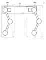
- FIG. 1 is a schematic diagram of an appearance of a robot 1 according to an embodiment of the present disclosure when viewed from above.
- FIG. 2 is a schematic diagram of an appearance when the robot 1 according to the embodiment of the present disclosure is viewed from the right side.
- the robot 1 includes a main body 10 and four legs 20.
- the main body 10 has a hollow part 110 which is a hollow space penetrating in the vertical direction.
- the four legs 20 are a leg 20a, a leg 20b, a leg 20c, and a leg 20d, respectively. Further, each of the four legs 20 may be configured to be detachable from the main body 10.
- the types of the legs 20 of the four legs can be all the same. However, the present invention is not limited to such an example, and leg portions 20 having different types such as a shaft configuration may be used together. Further, the number of the legs 20 is not limited to four. For example, the number of the legs 20 may be two or six.
- the side where the legs 20c and 20d are located with respect to the cutting line II is the right side of the main body 10, and the side where the legs 20a and 20b are located is the left side of the main body 10. Further, in the robot 1, the side where the legs 20b and 20d are located with respect to the cutting line II-II is the front side of the main body 10, and the side where the legs 20a and 20c are located is the rear side of the main body 10.
- FIG. 3 is a diagram (a cross-sectional view taken along the line II shown in FIG. 1) illustrating a cross section of the main body 10 according to the embodiment of the present disclosure cut along the long side direction.
- FIG. 4 is a diagram illustrating a cross section of the main body 10 according to the embodiment of the present disclosure cut along a short side (a cross-sectional view taken along a cutting line II-II illustrated in FIG. 1).
- the main body 10 has a hollow part 110 and a support part 120.
- the main body 10 inserts the support target into the hollow part 110 and supports the support target with the support part 120. Specifically, the main body 10 inserts the support target into the hollow portion 110 by moving at least downward when positioned on the support target.
- the support part 120 supports the support target inserted into the hollow part 110 by the main body part 10.
- the main body 10 lifts and supports the support target by moving at least upward when the support unit 120 supports the support target.
- the hollow part 110 is a hollow space penetrating the main body part 10 in the vertical direction.
- the hollow portion 110 is a space penetrating the upper surface and the lower surface of the main body 10.
- the hollow portion 110 is a space penetrating between the opening 111 (first opening) on the upper surface of the main body 10 and the opening 112 (second opening) on the lower surface of the main body 10. It is.
- the shape of the hollow portion 110 is, for example, a wedge shape.
- the wedge shape is formed by, for example, different areas of the opening 111 and the area of the opening 112. Specifically, the wedge shape is formed by the area of the opening 111 being smaller than the area of the opening 112, and has a shape that becomes thinner from the opening 112 toward the opening 111. Since the shape of the hollow portion 110 is a wedge shape, the hollow portion front surface 113, the hollow portion rear surface 114, the hollow portion right side surface 115, and the hollow portion left side surface 116 (hereinafter collectively referred to as the main body inner surface) inside the main body portion 10. (Also referred to as).
- the inclination is also referred to as the inclination of the inner surface of the main body.
- the main body part 10 can smoothly insert the support target 30 into the hollow part 110 by utilizing the inclination of the hollow part 110.
- the shape of the hollow portion is not limited to the wedge shape, and may be any shape. However, the hollow portion is desirably a wedge shape for smooth insertion of the support target 30.
- FIG. 5 is a diagram illustrating an example of inserting the support target 30 into the hollow portion 110 according to the embodiment of the present disclosure.
- the diagram shown on the left side of FIG. 5 is a diagram showing the state of the support target 30 before insertion, and the diagram shown on the right side of FIG. 5 is a diagram showing the state of the support target 30 after insertion.
- 5 are views of the robot 1 as viewed from above, and the lower and right views of FIG. 5 are at the cross-sectional positions along the cutting line II shown in FIG.
- FIG. 3 is a diagram illustrating a state of a support target 30.
- the position and the orientation of the support target 30 are desirably the positions and the orientations in which the support target 30 fits into the opening 111 without contacting the inner surface of the main body when the main body 10 moves downward. This is because, when the support target 30 comes into contact with the inner surface of the main body, for example, the support target 30 may not be inserted to the opening 111 and the main body 10 may not be able to support the support target. In that case, the main body 10 needs to repeat the operation of inserting the support target 30 into the hollow portion 110, which is inefficient. Specifically, when the position and the orientation of the support target 30 are the positions and the orientations shown in the diagram on the left side of FIG.
- the example has been described in which the position and the direction of the support target 30 are the position and the direction in which the support target 30 contacts the inner surface of the main body.
- at least one of the position and the orientation of the support target 30 may be the position or the orientation at which the support target 30 contacts the inner surface of the main body.
- the main body unit 10 can stably support and transport the support target 30 by supporting the support target 30 near the center of gravity of the main body unit 10. Therefore, it is desirable that the hollow portion 110 is formed at a position where the main body 10 can support the support target 30 near the center of gravity of the main body 10.
- the robot 1 supports the support target 30 in the vicinity of the center of gravity of the main body 10, thereby reducing the bias of the joint torque, the bias of the left and right front and rear torques, and the like, and can improve the stability of the posture of the robot 1. .
- FIG. 6 is a diagram illustrating an example of the position of the center of gravity of the supported object 30 according to the embodiment of the present disclosure.
- 6 is a diagram of the robot 1 as viewed from above.
- 6 is a view of the robot 1 as viewed from the right side.
- the position of the center of gravity 32 of the support target 30 when the robot 1 supports the support target 30 is located within a predetermined range 13 from the position of the center of gravity 12 of the main body 10.
- the position of the center of gravity of the hollow portion 110 is also within the predetermined range 13 from the position of the center of gravity 12 of the main body 10.
- the hollow portion 110 may be formed so as to be located. In the example shown in FIG. 6, the hollow portion 110 is formed such that the position of the center of gravity (not shown) of the hollow portion 110 is the same as the position of the center of gravity 12 of the main body portion 10.
- the support section 120 has a function of supporting the support target 30.
- the support portion 120 is configured by, for example, a claw 122 and a shaft portion 124, and supports the support target 30 by engaging the claw 122 with the support target 30.
- the pawl 122 is connected to a movable shaft portion 124 and operates according to the operation of the shaft portion 124.
- the shape of the claw 122 is, for example, a rectangle.
- the shaft 124 is provided on the inner surface of the main body.
- the shaft portion 124 has, for example, an elastic body such as a spring, and operates using the elastic force of the spring to move the claw 122 and engage the claw 122 with the support target 30.
- the support unit 120 may fix and support the support target 30 by fixing the claw 122 by a latch mechanism.
- two support portions 120a and 120b are provided on the hollow portion front surface 113 and the hollow portion rear surface 114, respectively.
- the configuration, the number, and the installation position of the support portions 120 are not limited to the above examples.
- the support unit 120 may be configured to support the support target 30 by attracting the support target 30 by magnetic force or air pressure.
- FIG. 7 is a diagram illustrating an example of support of the support target 30 by the support unit 120 according to the embodiment of the present disclosure.
- the diagram shown on the left side of FIG. 7 is a diagram showing the state of the support unit 120 before support, and the diagram shown on the right side of FIG. 7 is a diagram showing the state of the support unit 120 after support.
- the support part 120 is engaged with the support target 30 by moving the main part 10 downward along with the downward movement, so that the claw 122 is engaged with the concave part of the support target 30.
- the main body 10 inserts the support target 30 into the hollow part 110 by moving downward.
- the claws 122 of the support 120 come into contact with the support target 30.
- the pawl 122 is pushed up by the support target 30.
- the claw 122 moves to the position of the concave portion 31 of the support target 30.
- the claw 122 moves to the position of the concave portion 31, it engages with the concave portion 31 as shown in the diagram on the right side of FIG. 7. Thereby, the support part 120 can support the support target 30.
- the support portion 120 may have various configurations as a configuration for releasing the engagement between the support portion 120 and the support target 30 when the support of the support target 30 ends.
- the support 120 may include an actuator.
- the support unit 120 may move the claw 122 by driving the actuator to release the engagement between the claw 122 and the concave portion 31.
- the support unit 120 may have a mechanism in which the engagement between the support unit 120 and the support target 30 is released as the main body unit 10 moves.
- FIG. 8 is a diagram illustrating an example of an external configuration of the leg portion 20 according to the embodiment of the present disclosure.
- FIG. 9 is a diagram schematically illustrating a shaft configuration when the leg 20 according to the embodiment of the present disclosure is viewed from above.
- the leg 20 may be configured as a link mechanism including a plurality of joints 200 (movable parts) and a plurality of links 204, for example.
- the leg portion 20 includes, as a plurality of joint portions 200, a hip joint Roll axis 200a rotating in the Roll axis direction, a hip joint Pitch axis 200b rotating in the Pitch axis direction, and a knee joint Pitch axis 200c rotating in the Pitch axis direction.
- Each of the joints 200 has an actuator inside, and when the actuator is driven, it rotates in each axial direction. As shown in FIG. 9, these joints 200 may be arranged so that the rotation axis of the hip joint Pitch axis 200b and the rotation axis of the knee joint Pitch axis 200c are coaxial.
- the leg portion 20 has a link 204a that connects the hip joint Roll axis 200a and the hip joint Pitch axis 200b. Further, the leg 20 may have a closed link mechanism 206 connected to the hip joint Pitch axis 200b and the knee joint Pitch axis 200c. Thus, the force output by the actuator that drives the hip joint Pitch axis 200b can be transmitted to the knee joint Pitch axis 200c.
- the leg 20 has a toe 202 (tip).
- the toe 202 is provided at the tip of a link 204b included in the closed link mechanism 206.
- the toe 202 is in contact with a moving road surface on which the robot 1 moves.
- the toe 202 is covered with an elastomer or the like so that appropriate friction occurs between the toe 202 and the moving road surface.
- wheels may be provided on the toe 202.
- each leg 20 may be provided with a sensor for detecting a contact state between the toe 202 and the moving road surface, a contact state between the toe 202 and an object such as the support target 30, and the like.
- the robot 1 is configured such that, for each leg 20, when viewed from a fixed position of the leg 20 with respect to the main body 10 (for example, the position of the hip joint Roll axis 200a).
- the position of the toe 202 of the leg 20 can be moved in three directions: vertical, horizontal, and height.
- the robot 1 (more specifically, the main body 10) can apply a force in any direction in the external world by changing the position and the posture of each leg 20.
- the main body 10 can change the moment of the force by each leg 20 according to the magnitude of the frictional force when each leg 20 contacts another object, for example.
- the toe trajectory of each leg 20 can be a three-dimensional free trajectory, the robot 1 can also climb over or avoid one or more obstacles.
- the leg portion 20 bends and stretches by the movement of the joint portion 200, and moves the main body 10 at least in the vertical direction with the bending and stretching motion.
- the robot 1 raises and lowers the support target 30 by causing the leg portion 20 to perform a bending and stretching motion while the support portion of the main body portion 10 supports the support target 30 and moving the main body portion 10 in the vertical direction. Or you can.
- the robot 1 can carry the support target 30 by moving the leg 20 while the support target 30 is lifted and supported.
- the configuration of the leg 20 is not limited to the configuration in which the main body 10 is moved in the vertical direction by the bending and stretching motion.
- the configuration of the legs 20 may be a configuration in which the main body 10 is moved in the vertical direction by a linear motion.
- the shaft configuration of the leg 20 according to the present embodiment is not limited to the above-described example.
- the number of axes of the leg 20 may be one or more arbitrary numbers (for example, one axis or ten axes).
- all serial links may be used, all parallel links may be used, or one or more serial links and one or more parallel links are mixed. It may be.
- the leg 20 may have one or more under-driven joints (that is, joints that are not driven by the actuator).
- the number of actuators included in the leg 20 (the number of actuators that can be controlled by the leg 20) is not particularly limited.
- FIG. 10 is a block diagram illustrating a functional configuration example of the main body unit 10 according to the embodiment of the present disclosure.
- the robot 1 includes a control unit 100, a communication unit 102, a sensor unit 104, and a storage unit 106.
- Control unit 100 The control unit 100 has a function of controlling the operation of the robot 1. Processing performed by the control unit 100 in controlling the operation of the robot 1 will be described in detail.
- the control unit 100 performs a detection process based on the acquired information. For example, the control unit 100 causes the communication unit 102 included in the main body unit 10 of the robot 1 to communicate with the communication unit of the support target 30 so as to acquire the support target information. Then, the control unit 100 detects the position of the support target 30 based on the support target information acquired by the communication unit 102. In addition, the control unit 100 causes the sensor unit 104 provided in the main body unit 10 of the robot 1 to sense the support target 30 so as to acquire the support target information. Then, the control unit 100 detects the position of the support target 30 based on the support target information acquired by the sensor unit 104.
- control unit 100 detects a destination to which the support target 30 is transported based on the support target information acquired by the communication unit 102 or the sensor unit 104.
- the control unit 100 detects the posture of the robot 1 based on the support target information acquired by the communication unit 102 or the sensor unit 104.
- the support target information acquired by the above communication is, for example, position information of the support target 30.
- the position information may be position information registered in advance in the storage device by providing a storage device or the like in the support target 30, or may be position information sequentially acquired by providing a GPS (Global Positioning System) in the support target 30. It may be.
- the information acquired by the above-described sensing is, for example, a distance from the robot 1 to the support target 30. The distance is detected by being sensed by a camera or a distance measuring device included in the sensor unit 104.
- the support target 30 may include a QR code (registered trademark).
- the control unit 100 may acquire the support target information by reading the QR code with the camera of the sensor unit 104.
- the control unit 100 performs a determination process based on the information detected in the detection process. For example, based on the position of the support target 30 detected in the detection processing, the control unit 100 determines the position of the support target 30 as the position where the robot 1 performs the upward and downward operations. In the following, the upward movement of the robot 1 is also referred to as a rising operation, and the downward movement of the robot 1 is also referred to as a crouching movement.
- the position of the support target 30 is a support start position at which the robot 1 starts supporting the support target 30. Further, the control unit 100 determines the destination as a position at which the robot 1 performs the upward and downward operations based on the destination detected in the detection processing. The destination is a support end position at which the robot 1 stops supporting the support target 30.
- the control unit 100 performs an operation control process of the robot 1.
- the control unit 100 performs, for example, a process of moving the robot 1. Specifically, the control unit 100 moves the robot 1 to the execution position determined in the determination processing.
- the control unit 100 performs a process of moving the robot 1 upward and downward at the execution position. Specifically, the control unit 100 causes the robot 1 to move downward when the robot 1 moves to the execution position. On the other hand, when the robot 1 starts or ends supporting the support target 30 at the execution position, the control unit 100 causes the robot 1 to move upward.
- the control unit 100 performs a process of controlling the support operation of the robot 1. For example, when the robot 1 performs a downward motion, the support unit 120 of the robot 1 starts or ends supporting the support target 30. Specifically, when the support unit 120 does not support the support target 30, the control unit 100 causes the robot 1 to perform an operation from above the support target 30 to below. The control unit 100 causes the support unit 120 to start supporting the support target 30 by engaging the support unit 120 with the concave portion of the support target as the robot 1 moves downward. In addition, when the support unit 120 supports the support target, the control unit 100 causes the robot 1 to perform an operation in a downward direction and ground the support target 30.
- control unit 100 terminates the support of the support target 30 by causing the support unit 120 to release the engagement with the concave portion of the support target 30.
- control unit 100 causes the support unit 120 to release the engagement with the concave portion of the support target 30 by operating the mechanism of the support unit 120 in accordance with the operation of the robot 1.
- control unit 100 may move the support unit 120 by driving an actuator included in the shaft unit 124 of the support unit 120, and cause the support unit 120 to release the engagement with the concave portion of the support target 30.
- the control unit 100 performs processing for controlling the posture of the robot 1. For example, the control unit 100 detects the positional relationship between the hollow part 110 and the support target 30 based on the support target information detected in the detection processing, and based on the positional relationship, the posture of the support target 30 and the robot 1 The difference from the posture is detected. Next, based on the detected difference, the control unit 100 corrects the posture of the robot 1 according to the posture of the support target 30 so that the robot 1 can easily insert the support target 30 into the hollow part 110. Then, the control unit 100 causes the robot 1 to move downward in the corrected posture.
- FIG. 11 is a diagram illustrating an example of a posture control process of the robot 1 according to the embodiment of the present disclosure.
- the diagram shown on the left side of FIG. 11 is a diagram showing the posture of the robot 1 before correction.
- the diagram shown on the right side of FIG. 11 is a diagram showing the posture of the robot 1 after the correction.
- the robot 1 detects the inclination of the support target 30 based on the support target information detected in the detection processing.
- the robot 1 tilts the robot 1 in accordance with the detected tilt so that the main body 10 of the robot 1 and the upper surface of the support target 30 are horizontal. 1 is corrected. Then, the robot 1 performs an operation in the downward direction with the corrected posture.
- the communication unit 102 has a function of performing communication with an external device. For example, the communication unit 102 transmits and receives information by communicating with a communication unit included in the support target 30. Specifically, the communication unit 102 receives the support target information via communication with the communication unit of the support target 30. Then, the communication unit 102 outputs the received support target information to the control unit 100.
- the sensor unit 104 has a function of acquiring support target information on the support target 30.
- the sensor unit 104 may include various sensors to acquire the support target information.
- the sensor unit 104 may include a camera, a thermo camera, a depth sensor, a microphone (hereinafter also referred to as a microphone), and an inertial sensor. Note that the sensor unit 104 may include one or a combination of these, or may include a plurality of devices of the same type.
- the camera is an imaging device that has a lens system, a driving system, and an imaging element, such as an RGB camera, and captures an image (still image or moving image).
- a thermo camera is an imaging device that captures a captured image including information indicating the temperature of an imaging target using infrared light or the like.
- the depth sensor is a device that acquires depth information such as an infrared distance measuring device, an ultrasonic distance measuring device, a LiDAR (Laser Imaging Detection and Ranging), or a stereo camera.
- the microphone is a device that collects surrounding sounds and outputs audio data converted into digital signals via an amplifier and an ADC (Analog Digital Converter).
- An inertial sensor is a device that detects acceleration and angular velocity.
- the camera, the thermo camera, and the depth sensor can be used to detect the distance between the robot 1 and the support target 30 and to detect the positional relationship between the robot 1 and the support target 30 based on the detected distance.
- the microphone can be used to detect sound waves output from the support object 30 and to detect the support object 30 based on the detected sound waves.
- the inertial sensor can be used for detecting the postures of the robot 1 and the support target 30.
- sensors can be installed in various ways. These sensors are installed in the main body 10 of the robot 1, for example. Specifically, these sensors may be installed on any of the upper surface, the lower surface, the side surfaces, and the inner surface of the main body 10. Further, these sensors may be installed on the leg 20. Specifically, these sensors may be installed on the joint 200 of the leg 20, the toe 202, the link 204, and the closed link mechanism 206.
- the storage unit 106 has a function of storing data obtained by the processing in the control unit 100.
- the storage unit 106 stores the support target information received by the communication unit 102.
- the storage unit 106 may store data detected by the sensor unit 104.
- the storage unit 106 may store control information of the robot 1 output by the control unit 100. Note that the information stored in the storage unit 106 is not limited to the above example.
- the storage unit 106 may store programs such as various applications, data, and the like.
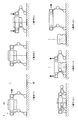
- FIG. 12 is a diagram illustrating a flow of the support start operation of the robot 1 according to the embodiment of the present disclosure.
- the robot 1 determines the support start position 41 of the support target 30 by detecting the support target 30 and starts moving to the support start position 41 (operation 1).
- the robot 1 moves to the support start position 41 (operation 2).
- the robot 1 starts crouching operation at the support start position 41 (operation 3).
- the robot 1 supports the support target 30 by the crouching operation (operation 4).
- the robot 1 starts a rising operation (operation 5).
- the robot 1 transports the support target 30 to the destination (operation 6).
- FIG. 13 is a flowchart illustrating the flow of the support start operation process in the control unit 100 according to the embodiment of the present disclosure.
- the control unit 100 detects the support target 30 based on the sensing data detected by the sensor unit 104 (step S1000).
- the control unit 100 determines the support start position 41 of the support target 30 based on the detection result of the support target 30 (step S1002).
- the control unit 100 moves the robot 1 to the support start position 41 by driving the leg 20 of the robot 1 (step S1004).
- the control unit 100 drives the leg 20 of the robot 1 at the support start position 41 to cause the robot 1 to perform a squatting operation and support the support target 30 (step S1006).
- control unit 100 After the support target 30 is supported, the control unit 100 causes the robot 1 to perform a rising operation by driving the leg unit 20 (step S1008). After the completion of the rising operation, the control unit 100 moves the robot 1 to the destination while supporting the support target 30 (step S1010).
- FIG. 14 is a diagram illustrating a flow of the support end operation of the robot 1 according to the embodiment of the present disclosure.
- the robot 1 executes the operations shown in FIG. First, the robot 1 detects a destination to which the support target 30 is to be transported, thereby determining a support end position 42 at which the supported support target 30 is lowered to end support, and a support end position. The movement to 42 is started (operation 7). The robot 1 moves to the support end position 42 (operation 8). After moving to the support end position 42, the robot 1 starts crouching operation at the support end position 42 (operation 9).
- the robot 1 releases the support target 30 to terminate the support of the support target 30 (operation 10). After the support of the support target 30 is completed, the robot 1 starts a rising operation (operation 11). After standing up, the robot 1 starts moving to the position of the support target 30 to be transported next (operation 12).
- FIG. 15 is a flowchart illustrating the flow of the support end operation process in the control unit 100 according to the embodiment of the present disclosure.
- the control unit 100 detects a destination based on the sensing data detected by the sensor unit 104 (step S2000). Based on the result of the detection of the destination, the control unit 100 determines the support end position 42 of the support target 30 (Step S2002).
- the control unit 100 moves the robot 1 to the support end position 42 by driving the leg 20 of the robot 1 (step S2004).
- the control unit 100 causes the robot 1 to perform a crouching operation by driving the leg 20 of the robot 1 at the support end position 42 (step S2006).
- control unit 100 causes the robot 1 to stop supporting the support target 30 (step S2008). After the support mechanism finishes supporting the support target, the control unit 100 causes the robot 1 to perform a rising operation by driving the leg 20 of the robot 1 (step S2010). After the start-up operation is completed, the control unit 100 moves the robot 1 to the position of the support target 30 to be transported next (step S2012).
- Example An example according to the embodiment of the present disclosure will be described with reference to FIGS. 16 to 21.
- the examples described below may be applied to the embodiments of the present disclosure by themselves, or may be applied to the embodiments of the present disclosure in combination. Further, the example may be applied instead of the configuration described in the embodiment of the present disclosure, or may be additionally applied to the configuration described in the embodiment of the present disclosure.
- FIG. 16 is a diagram illustrating an example of a method for detecting the support target 30 according to the embodiment of the present disclosure.
- the robot 1 detects the support target 30 by acquiring information output by the support target 30, for example.
- the output device 33 included in the support target 30 outputs a sound wave 34 having a specific frequency known by the robot 1.
- the robot 1 includes a microphone 104a as the sensor unit 104, and acquires the sound wave 34 by the microphone 104a.
- the robot 1 detects the support target 30 based on the acquired sound waves 34. Then, the robot 1 detects a relative positional relationship between the robot 1 and the support target 30 based on the detected position of the support target 30.
- the position where the microphone 104a is installed is not limited, and is installed at an arbitrary position of the robot 1.
- the microphone 104a may be installed at a circular position on the upper surface of the main unit 10, as shown in FIG. 16, or may be set at a triangular position on the lower surface of the main unit 10.
- FIG. 17 is a diagram illustrating an example of a posture control process using communication according to the embodiment of the present disclosure.
- the robot 1 receives, for example, the support target information transmitted from the communication unit included in the support target 30 by the communication unit 102, and controls the posture of the robot 1 based on the received support target information.
- the robot 1 corrects the attitude of the robot 1 with respect to the Roll axis and the Pitch axis, for example.
- the support target 30 includes, for example, an acceleration sensor, and detects inclination information of the support target 30 with respect to the gravity 35 by the acceleration sensor. Then, the support target 30 transmits the support target information including the detected tilt information to the communication unit 102 of the robot 1 by wireless communication 36.
- FIG. 18 is a diagram illustrating an example of a posture control process using the distance measurement sensor according to the embodiment of the present disclosure.
- the robot 1 performs the posture control process based on the support target information acquired by the distance measurement sensor 104b.
- the robot 1 includes, for example, a distance measuring sensor 104 b at a circle position between a hollow front surface 113 and a hollow left side surface 116 on the inner surface of the main body.
- the robot 1 includes the distance measurement sensors 104b on at least two inner surfaces of the main body, thereby acquiring posture information of the support target 30 inserted into the hollow portion 110 on the two surfaces.
- the posture information includes, for example, an angle indicating the inclination of the support target 30.
- the robot 1 detects a relative distance and an angle between the hollow portion 110 and the support target 30 based on the acquired posture information of the support target 30. Then, the robot 1 corrects the posture of the robot 1 based on the detected relative distance and angle so that the support target 30 is inserted in conformity with the hollow portion 110. At this time, the robot 1 corrects the attitude of the robot 1 with respect to the Yaw axis, for example.
- the surface on which the distance measuring sensor 104b is installed on the inner surface of the main body is not particularly limited. Further, the position on the inner surface of the main body where the distance measuring sensor 104b is installed is not particularly limited. However, it is desirable that the distance measurement sensor 104b is not installed linearly on one of the inner surfaces of the main body. For example, as shown in FIG. 18, since the distance measuring sensor 104b is not installed on a straight line, the surface of the support target 30 is easily detected.
- FIG. 19 is a diagram illustrating an example of a posture control process using the laser light source according to the embodiment of the present disclosure.
- the robot 1 performs the posture control process based on the support target information acquired by the camera 104c and the laser light source 104d.
- the robot 1 has a camera 104c at a round position on the inner surface of the main body and a laser light source 104d at a triangular position.
- the robot 1 causes the laser light source 104d to output a linear laser beam 14 in a diagonal direction of the installation position, and causes the camera 104c to image the reflected light when the laser beam 14 is reflected by the support target 30.
- the robot 1 detects the relative position and orientation between the hollow part 110 and the support target 30 based on the image captured by the camera 104c. Then, the robot 1 corrects the posture of the robot 1 based on the detected relative position and posture so that the support target 30 is inserted in conformity with the hollow portion 110. At this time, the robot 1 corrects the attitude of the robot 1 with respect to the Yaw axis, for example.
- the surface on which the camera 104c and the laser light source 104d are installed on the inner surface of the main body is not particularly limited.
- positions on the inner surface of the main body where the camera 104c and the laser light source 104d are installed are not particularly limited.
- the laser light source 104d outputs the laser beam 14 so as not to be parallel to any side of any surface of the inner surface of the main body.
- the laser light source 104d may be provided for any side of each surface, such as the laser beam 14a applied to the front surface 113 of the hollow portion and the laser beam 14b applied to the left side surface 116 of the hollow portion shown in FIG. The laser beam 14 is output so as not to be parallel. Thereby, the surface of the support target 30 is easily detected.
- FIG. 20 is a diagram illustrating an example of correction of the inclination of the support target 30 by the protrusion 40 according to the embodiment of the present disclosure.
- the robot 1 pushes the support target 30 with the main body 10 as shown in the upper part of FIG.
- the robot 1 moves the support target 30 to a position where the tilt of the support target 30 stops as shown in the middle part of FIG.
- the robot 1 starts the support operation as shown in the lower part of FIG.
- FIG. 21 is a diagram illustrating an example of correction of the inclination of the support target 30 due to the depression according to the embodiment of the present disclosure.
- the robot 1 pushes the support target 30 with the main body 10 as shown in the upper part of FIG.
- the robot 1 moves the support target 30 to a position where the tilt of the support target 30 stops as shown in the middle part of FIG. 21.
- the robot 1 starts the support operation as shown in the lower part of FIG.
- the robot 1 determines whether or not the support target 30 is tilted, and then performs the operation of pushing the support target 30 with the main body unit 10 described above. For example, the robot 1 determines whether or not the support target 30 is tilted based on an image captured by a camera included in the sensor unit 104. Specifically, the robot 1 previously holds an image when the support target 30 is in a horizontal state in a storage unit or the like, and compares the image with an image captured by a camera, so that the support target 30 is tilted. Is determined. Further, the robot 1 may determine whether or not the support target 30 is tilted based on information sensed by an acceleration sensor included in the support target 30. Further, when determining that the support target 30 is inclined, the robot 1 may move the support target 30 by putting a bag or a net on the support target 30 and pulling the bag or the net.
- FIG. 22 is a diagram illustrating a modification according to the embodiment of the present disclosure.
- the robot 1 has the support portion 120
- the support target 30 has the concave portion 31, and the robot 1 supports the support target 30 by moving upward and downward.
- the robot 1 has the convex portion 126
- the support target 37 has the handle 38
- the robot 1 supports the support target 37 by operating in the up-down direction and the front-back direction.
- the main body 10 of the robot 1 has a convex portion 126.
- the support target 37 has a handle 38.
- the robot 1 executes the operations shown in FIG. First, the robot 1 moves to the position of the support target 37 (operation 13). Next, the robot 1 puts the handle 38a on the convex portion 126a by moving the main body 10 in combination with the vertical movement and the front-back movement (operation 14). Next, the robot 1 moves the protrusion 126b to the lower side of the handle 38b by moving the main body 10 in combination with the movement in the up-down direction and the movement in the front-rear direction (operation 15). Then, the robot 1 places the handle 38 on the projection 126b by moving the main body 10 upward (operation 16). The robot 1 can lift the support target 37 by further performing an upward operation in a state where the operation 16 is completed.
- FIG. 23 is a block diagram illustrating a hardware configuration example of the robot 900 according to the present embodiment.
- Information processing in the robot 900 according to the present embodiment is realized by cooperation between software and hardware described below.
- the robot 900 includes a CPU (Central Processing Unit) 901, a ROM (Read Only Memory) 903, and a RAM (Random Access Memory) 905.
- the robot 900 includes a host bus 907, a bridge 909, an external bus 911, an interface 913, an input device 915, a storage device 917, and a communication device 919.
- the hardware configuration shown here is an example, and some of the components may be omitted. Further, the hardware configuration may further include components other than the components shown here.
- the CPU 901 functions as, for example, an arithmetic processing device or a control device, and controls the entire operation of each component or a part thereof based on various programs recorded in the ROM 903, the RAM 905, or the storage device 917.
- the ROM 903 is a unit that stores programs read by the CPU 901, data used for calculations, and the like.
- the RAM 905 temporarily or permanently stores, for example, a program read by the CPU 901 and various parameters that appropriately change when the program is executed. These are mutually connected by a host bus 907 including a CPU bus and the like.
- the CPU 901, the ROM 903, and the RAM 905 can realize the function of the control unit 100 described with reference to FIG. 10, for example, in cooperation with software.
- the CPU 901, the ROM 903, and the RAM 905 are connected to each other via a host bus 907 capable of high-speed data transmission, for example.
- the host bus 907 is connected to, for example, an external bus 911 having a relatively low data transmission speed via a bridge 909.
- the external bus 911 is connected to various components via an interface 913.
- the input device 915 is realized by a device to which information is input by a user, such as a mouse, a keyboard, a touch panel, a button, a microphone, a switch, and a lever. Further, the input device 915 may be, for example, a remote control device using infrared rays or other radio waves, or may be an externally connected device such as a mobile phone or a PDA compatible with the operation of the robot 900. Further, the input device 915 may include, for example, an input control circuit that generates an input signal based on information input by a user using the above-described input unit and outputs the input signal to the CPU 901. By operating the input device 915, the user of the robot 900 can input various data to the robot 900 and instruct a processing operation.
- the input device 915 may be formed by a device that detects information about a user.
- the input device 915 includes various sensors such as an image sensor (for example, a camera), a depth sensor (for example, a stereo camera), an acceleration sensor, a gyro sensor, a geomagnetic sensor, an optical sensor, a sound sensor, a distance measuring sensor, and a force sensor. May be included.
- the input device 915 may acquire information on the state of the robot 900 itself, such as the posture and the moving speed of the robot 900, and information on the surrounding environment of the robot 900, such as brightness and noise around the robot 900.
- the input device 915 receives a GNSS signal from a GNSS (Global Navigation Satellite System) satellite (for example, a GPS signal from a GPS (Global Positioning System) satellite) and receives position information including the latitude, longitude, and altitude of the device.
- GNSS Global Navigation Satellite System
- a GNSS module for measuring may be included.
- the input device 915 may be a device that detects the position by Wi-Fi (registered trademark), transmission / reception with a mobile phone / PHS / smartphone, or the like, or short-range communication.
- the input device 915 can realize, for example, the function of the sensor unit 104 described with reference to FIG.
- the storage device 917 is a device for storing data formed as an example of a storage unit of the robot 900.
- the storage device 917 is realized by, for example, a magnetic storage device such as an HDD, a semiconductor storage device, an optical storage device, or a magneto-optical storage device.
- the storage device 917 may include a storage medium, a recording device that records data on the storage medium, a reading device that reads data from the storage medium, a deletion device that deletes data recorded on the storage medium, and the like.
- the storage device 917 stores programs executed by the CPU 901 and various data, various data acquired from the outside, and the like.
- the storage device 917 can realize, for example, the function of the storage unit 106 described with reference to FIG.
- the communication device 919 is, for example, a communication interface formed by a communication device or the like for connecting to the network 921.
- the communication device 919 is, for example, a communication card for a wired or wireless LAN (Local Area Network), LTE (Long Term Evolution), Bluetooth (registered trademark), or WUSB (Wireless USB).
- the communication device 919 may be a router for optical communication, a router for ADSL (Asymmetric Digital Subscriber Line), a modem for various kinds of communication, or the like.
- the communication device 919 can transmit and receive signals and the like to and from the Internet and other communication devices in accordance with a predetermined protocol such as TCP / IP.
- the network 921 is a wired or wireless transmission path for information transmitted from a device connected to the network 921.
- the network 921 may include a public line network such as the Internet, a telephone line network, and a satellite communication network, various LANs including Ethernet (registered trademark) (Local Area Network), a WAN (Wide Area Network), and the like.
- the network 921 may include a dedicated line network such as an IP-VPN (Internet ⁇ Protocol-Virtual ⁇ Private ⁇ Network).
- the robot 1 has the hollow portion 110 that is a hollow space penetrating in the vertical direction, and the support target inserted into the hollow portion 110 as the robot moves in the vertical direction.
- the main body 10 is provided for lifting and supporting the main body 30.
- the robot 1 includes a movable unit that moves the main unit 10 at least in the vertical direction by operating the leg unit 20.
- the robot 1 can load and unload and carry a load without providing an arm device outside the main body 10.
- a body portion having a hollow portion that is a hollow space penetrating in the up-down direction, and lifting and supporting a support target inserted into the hollow portion along with the up-down movement, A movable unit configured to move the main unit at least in the vertical direction by operating a leg unit.
- the robot according to (1) wherein the main body section moves the at least downward direction when the main body section is positioned above the support target, thereby inserting the support target into the hollow portion.
- the main body has a support for supporting the support target, The robot according to (1) or (2), wherein the support unit supports the support target when the support target is inserted into the hollow portion.
- the robot according to (3) wherein the support unit has a movable claw, and supports the support target by engaging the claw with the support target.
- the shape of the hollow portion is a wedge shape, The robot according to any one of (1) to (5), wherein the wedge shape is formed by different areas of the first opening and the second opening of the hollow portion. . (7) The robot according to any one of (1) to (6), wherein the position of the center of gravity of the hollow portion is a position within a predetermined range from the position of the center of gravity of the main body.
- the legs are composed of a plurality of links and a plurality of movable parts, and perform bending and stretching movements by operating the movable parts to move the main body at least in the vertical direction.
- the robot according to any one of the above.
- a control method executed by a processor including: (12) The processor according to (11), wherein, based on the support target information, the processor detects a position of the support target, and determines the detected position of the support target as an execution position of the operation in the upward direction and the downward direction. The control method described. (13) The control method according to (12), wherein the processor moves the control target to the execution position and causes the control target to execute the upward and downward operations.
- the processor detects a positional relationship between the hollow portion and the support target based on the support target information, and detects a difference between the attitude of the support target and the attitude of the control target based on the positional relationship, The control method according to any one of (11) to (13).
- Method (16) The processor according to any one of (11) to (15), wherein, when the control target performs the downward operation, the processor starts or ends the support of the support target by the support unit of the control target.
- the processor when the support unit does not support the support target, by causing the control target to perform an operation from the top of the support target to the downward direction, the support unit to support the support target.
- (19) The control method according to any one of (11) to (18), wherein the processor causes the sensor unit included in the control target to sense the support target to acquire the support target information.
- the processor causes the communication unit included in the control target to perform communication with the communication unit of the support target to acquire the support target information.
Landscapes
- Engineering & Computer Science (AREA)
- Mechanical Engineering (AREA)
- Transportation (AREA)
- Chemical & Material Sciences (AREA)
- Combustion & Propulsion (AREA)
- Multimedia (AREA)
- Robotics (AREA)
- Manipulator (AREA)
Abstract
La présente invention se rapporte à un robot (1) qui comprend : une partie corps (10) incluant une section creuse (110) qui est un espace creux pratiqué dans la partie corps dans la direction verticale, et soulevant et portant un objet à porter (30) introduit dans la section creuse (110) pendant un mouvement dans la direction verticale ; et une unité mobile (200) faisant bouger cette partie corps (10) au moins dans la direction verticale grâce à un mouvement d'une partie jambe (20).
Priority Applications (3)
| Application Number | Priority Date | Filing Date | Title |
|---|---|---|---|
| US17/253,879 US20210245647A1 (en) | 2018-06-26 | 2019-06-19 | Robot and control method |
| CN201980041417.3A CN112334282A (zh) | 2018-06-26 | 2019-06-19 | 机器人和控制方法 |
| JP2020527449A JP7279717B2 (ja) | 2018-06-26 | 2019-06-19 | ロボット、及び制御方法 |
Applications Claiming Priority (2)
| Application Number | Priority Date | Filing Date | Title |
|---|---|---|---|
| JP2018-121050 | 2018-06-26 | ||
| JP2018121050 | 2018-06-26 |
Publications (1)
| Publication Number | Publication Date |
|---|---|
| WO2020004204A1 true WO2020004204A1 (fr) | 2020-01-02 |
Family
ID=68985085
Family Applications (1)
| Application Number | Title | Priority Date | Filing Date |
|---|---|---|---|
| PCT/JP2019/024385 Ceased WO2020004204A1 (fr) | 2018-06-26 | 2019-06-19 | Robot et procédé de commande |
Country Status (4)
| Country | Link |
|---|---|
| US (1) | US20210245647A1 (fr) |
| JP (1) | JP7279717B2 (fr) |
| CN (1) | CN112334282A (fr) |
| WO (1) | WO2020004204A1 (fr) |
Cited By (3)
| Publication number | Priority date | Publication date | Assignee | Title |
|---|---|---|---|---|
| US10190199B2 (en) | 2006-12-01 | 2019-01-29 | Ormco Corporation | Method of alloying reactive components |
| WO2021079578A1 (fr) * | 2019-10-25 | 2021-04-29 | ソニー株式会社 | Dispositif robotisé |
| JP2025510520A (ja) * | 2022-02-28 | 2025-04-15 | フラウンホーファー-ゲゼルシャフト・ツール・フェルデルング・デル・アンゲヴァンテン・フォルシュング・アインゲトラーゲネル・フェライン | 積荷の輸送用の移動プラットフォームのための、および移動プラットフォームを有する装置ならびに方法 |
Families Citing this family (1)
| Publication number | Priority date | Publication date | Assignee | Title |
|---|---|---|---|---|
| WO2025013961A1 (fr) * | 2023-07-10 | 2025-01-16 | 엘지전자 주식회사 | Dispositif d'accueil, robot mobile et procédé de commande associé |
Citations (7)
| Publication number | Priority date | Publication date | Assignee | Title |
|---|---|---|---|---|
| JPS56106941U (fr) * | 1980-01-18 | 1981-08-20 | ||
| JPH0633689U (ja) * | 1992-10-14 | 1994-05-06 | 鐘紡株式会社 | エアチューブチャック |
| JPH06226661A (ja) * | 1993-02-09 | 1994-08-16 | Toshiba Corp | ロボットモジュールおよびロボット |
| JP2005245637A (ja) * | 2004-03-02 | 2005-09-15 | Sanyo Electric Co Ltd | 歩行補助装置 |
| JP2016020103A (ja) * | 2014-07-11 | 2016-02-04 | 株式会社東芝 | 運搬装置 |
| JP2016074060A (ja) * | 2014-10-07 | 2016-05-12 | 株式会社東芝 | 遠隔作業自動機及びその作業方法 |
| JP2017109294A (ja) * | 2015-12-18 | 2017-06-22 | 清水建設株式会社 | 建設作業用ロボット |
Family Cites Families (4)
| Publication number | Priority date | Publication date | Assignee | Title |
|---|---|---|---|---|
| JP3553184B2 (ja) * | 1995-03-23 | 2004-08-11 | 本田技研工業株式会社 | 表面処理機構を備えた吸着式壁面歩行装置 |
| US6019565A (en) * | 1996-11-12 | 2000-02-01 | Gesuale; Thomas | Container lifting and transport apparatus |
| US9962832B2 (en) | 2013-03-04 | 2018-05-08 | President And Fellows Of Harvard College | Magnetic assembly of soft robots with hard components |
| CN106904226B (zh) * | 2017-03-10 | 2022-12-23 | 杭州宇树科技有限公司 | 一种电驱动四足机器人的腿部动力系统结构 |
-
2019
- 2019-06-19 CN CN201980041417.3A patent/CN112334282A/zh not_active Withdrawn
- 2019-06-19 WO PCT/JP2019/024385 patent/WO2020004204A1/fr not_active Ceased
- 2019-06-19 JP JP2020527449A patent/JP7279717B2/ja active Active
- 2019-06-19 US US17/253,879 patent/US20210245647A1/en not_active Abandoned
Patent Citations (7)
| Publication number | Priority date | Publication date | Assignee | Title |
|---|---|---|---|---|
| JPS56106941U (fr) * | 1980-01-18 | 1981-08-20 | ||
| JPH0633689U (ja) * | 1992-10-14 | 1994-05-06 | 鐘紡株式会社 | エアチューブチャック |
| JPH06226661A (ja) * | 1993-02-09 | 1994-08-16 | Toshiba Corp | ロボットモジュールおよびロボット |
| JP2005245637A (ja) * | 2004-03-02 | 2005-09-15 | Sanyo Electric Co Ltd | 歩行補助装置 |
| JP2016020103A (ja) * | 2014-07-11 | 2016-02-04 | 株式会社東芝 | 運搬装置 |
| JP2016074060A (ja) * | 2014-10-07 | 2016-05-12 | 株式会社東芝 | 遠隔作業自動機及びその作業方法 |
| JP2017109294A (ja) * | 2015-12-18 | 2017-06-22 | 清水建設株式会社 | 建設作業用ロボット |
Cited By (4)
| Publication number | Priority date | Publication date | Assignee | Title |
|---|---|---|---|---|
| US10190199B2 (en) | 2006-12-01 | 2019-01-29 | Ormco Corporation | Method of alloying reactive components |
| WO2021079578A1 (fr) * | 2019-10-25 | 2021-04-29 | ソニー株式会社 | Dispositif robotisé |
| US12060124B2 (en) | 2019-10-25 | 2024-08-13 | Sony Group Corporation | Robot device |
| JP2025510520A (ja) * | 2022-02-28 | 2025-04-15 | フラウンホーファー-ゲゼルシャフト・ツール・フェルデルング・デル・アンゲヴァンテン・フォルシュング・アインゲトラーゲネル・フェライン | 積荷の輸送用の移動プラットフォームのための、および移動プラットフォームを有する装置ならびに方法 |
Also Published As
| Publication number | Publication date |
|---|---|
| JP7279717B2 (ja) | 2023-05-23 |
| US20210245647A1 (en) | 2021-08-12 |
| CN112334282A (zh) | 2021-02-05 |
| JPWO2020004204A1 (ja) | 2021-07-08 |
Similar Documents
| Publication | Publication Date | Title |
|---|---|---|
| WO2020004204A1 (fr) | Robot et procédé de commande | |
| JP6904992B2 (ja) | 自然なピッチとロール | |
| US9513714B2 (en) | Methods and apparatuses for gesture-based user input detection in a mobile device | |
| US20240152143A1 (en) | Systems and methods for ground plane estimation | |
| ES2541303T3 (es) | Sistema de medición multidimensional | |
| JP6724349B2 (ja) | 自律移動装置、自律移動方法及びプログラム | |
| US9662791B1 (en) | Systems and methods for robotic self-right | |
| US20170192517A1 (en) | Modular sensing device for controlling a self-propelled device | |
| KR100776849B1 (ko) | 레그식 로봇의 제어 장치 | |
| US20240066691A1 (en) | Robot device and method for controlling the same | |
| JP6950638B2 (ja) | マニピュレータ制御装置、マニピュレータ制御方法、及びマニピュレータ制御プログラム | |
| JP2018047538A (ja) | ロボット、状態判定システム、状態判定方法及びプログラム | |
| JP2018185767A (ja) | 環境整備ロボットおよびその制御プログラム | |
| JP2018043601A (ja) | 飛行装置、飛行装置制御プログラム及び飛行装置制御方法 | |
| US12130634B2 (en) | Mobile object control device and mobile object control method | |
| KR20070062424A (ko) | 각식 이동 로봇의 제어장치 | |
| JP7798545B2 (ja) | 判定装置、判定システム、判定方法及びプログラム | |
| WO2025044456A1 (fr) | Procédé et appareil de commande de position debout autonome, robot et support d'enregistrement lisible par ordinateur | |
| TW202450337A (zh) | 功率高效、性能高效以及情境自適應姿態追蹤 | |
| Buschmann et al. | Grid-based navigation for autonomous, mobile robots | |
| Gupta et al. | A carrying task for nonprehensile mobile manipulators | |
| WO2020000233A1 (fr) | Plate-forme mobile et procédé de commande associé | |
| JP2019141966A (ja) | ロボット制御装置、ロボット、及びロボットシステム | |
| WO2024252612A1 (fr) | Unité de commande, corps mobile, dispositif de robot mobile, procédé de commande et support de stockage | |
| KR100567184B1 (ko) | 이족보행로봇의 실시간 자세제어 장치 및 방법 |
Legal Events
| Date | Code | Title | Description |
|---|---|---|---|
| 121 | Ep: the epo has been informed by wipo that ep was designated in this application |
Ref document number: 19827357 Country of ref document: EP Kind code of ref document: A1 |
|
| WWE | Wipo information: entry into national phase |
Ref document number: 2020527449 Country of ref document: JP |
|
| NENP | Non-entry into the national phase |
Ref country code: DE |
|
| 122 | Ep: pct application non-entry in european phase |
Ref document number: 19827357 Country of ref document: EP Kind code of ref document: A1 |