WO2020004584A1 - Procédé d'intégration d'un groupe de corps d'emballage - Google Patents
Procédé d'intégration d'un groupe de corps d'emballage Download PDFInfo
- Publication number
- WO2020004584A1 WO2020004584A1 PCT/JP2019/025702 JP2019025702W WO2020004584A1 WO 2020004584 A1 WO2020004584 A1 WO 2020004584A1 JP 2019025702 W JP2019025702 W JP 2019025702W WO 2020004584 A1 WO2020004584 A1 WO 2020004584A1
- Authority
- WO
- WIPO (PCT)
- Prior art keywords
- package
- packages
- connecting portion
- group
- package group
- Prior art date
- Legal status (The legal status is an assumption and is not a legal conclusion. Google has not performed a legal analysis and makes no representation as to the accuracy of the status listed.)
- Ceased
Links
Images






Classifications
-
- B—PERFORMING OPERATIONS; TRANSPORTING
- B65—CONVEYING; PACKING; STORING; HANDLING THIN OR FILAMENTARY MATERIAL
- B65B—MACHINES, APPARATUS OR DEVICES FOR, OR METHODS OF, PACKAGING ARTICLES OR MATERIALS; UNPACKING
- B65B13/00—Bundling articles
-
- B—PERFORMING OPERATIONS; TRANSPORTING
- B65—CONVEYING; PACKING; STORING; HANDLING THIN OR FILAMENTARY MATERIAL
- B65B—MACHINES, APPARATUS OR DEVICES FOR, OR METHODS OF, PACKAGING ARTICLES OR MATERIALS; UNPACKING
- B65B13/00—Bundling articles
- B65B13/18—Details of, or auxiliary devices used in, bundling machines or bundling tools
Definitions
- the present invention relates to a method for integrating a group of packages having a plurality of packages for packing articles.
- the goods are manufactured, they are stored in packages such as cardboard and transported.
- packages such as cardboard and transported.
- the plurality of packages may be transported in a state of being stacked on each other. In this case, it is necessary to prevent the stacked state of the plurality of packages from being disrupted and to prevent damage to the articles in the packages.
- Patent Document 1 discloses a method of packing an inorganic molded article such that a product surface of the inorganic molded article such as a roof tile is not damaged during transportation or storage, and cracks or chips are not generated.
- the method described in Patent Literature 1 includes a step of vertically loading a package on which an inorganic molded body is packed on an inclined pallet on a pallet surface, and packing the entire pallet on which the package is loaded with a film. Performing the steps.
- Patent Document 2 discloses a method of integrating a package. In this method, first, glue is ejected onto the upper surface of the package to form a glue surface. Then, another package is laminated on the package on which the glue surface is formed. Thereby, the packages adjacent to each other in the height direction are fixed to each other by the glue. Thereby, the collapse of the load is prevented.
- Patent Literature 1 a group of packages is integrated by wrapping a plurality of packages together with a film on a pallet.
- the number of members (films) necessary for integrating the package group increases.
- the work efficiency is low, and the necessary devices may be complicated and / or large.
- the package group that can easily grasp the state of integration of the package groups (the state of the connection part) can be easily integrated. Is desired.
- a method of integrating a group of packages having a plurality of packages includes forming a connecting portion that connects the packages to each other by spraying a thermoplastic resin on portions where the packages are adjacent to each other. Process.
- FIG. 1 is a perspective view showing a schematic configuration of a system for integrating a package group.
- FIG. 2 is a side view of a portion near the gate of the system of FIG. 1 as viewed from the side.
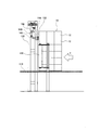
- FIG. 3 is a diagram illustrating one step of a method of integrating the package group according to the first embodiment.
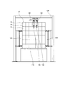
- FIG. 4 is a diagram showing steps subsequent to FIG.
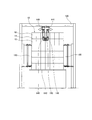
- FIG. 5 is a diagram showing a step following FIG.
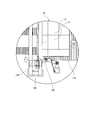
- FIG. 6 is a partially enlarged view as seen from the direction of arrow 6A shown in FIG.
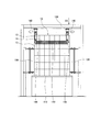
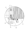
- FIG. 7 is a partially enlarged view showing a step following FIGS. 5 and 6.
- FIG. 8 is a diagram showing steps subsequent to FIG.
- FIG. 9 is a partially enlarged view showing a step following FIG. FIG.
- FIG. 10 is a partially enlarged view showing a step following FIG. 9.
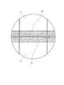
- FIG. 11 is a schematic diagram of a thermoplastic resin forming a connecting portion that connects the packages to each other.
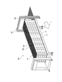
- FIG. 12 is a schematic diagram illustrating a position of a connecting portion in the package group according to the second embodiment.
- FIG. 13 is a schematic diagram illustrating a position of a connecting portion in the package group according to the third embodiment.
- FIG. 14 is a schematic diagram illustrating a position of a connecting portion in the package group according to the fourth embodiment.
- a method of integrating a group of packages having a plurality of packages according to one aspect is to form a connecting portion that connects the packages to each other by spraying a thermoplastic resin on portions where the packages are adjacent to each other.
- a connecting portion forming step is to form a connecting portion that connects the packages to each other by spraying a thermoplastic resin on portions where the packages are adjacent to each other.
- thermoplastic resin By spraying the thermoplastic resin, a connection portion is locally formed at a portion required for integrating the packages, so that a member (thermoplastic resin) necessary for integrating the packages is formed. The amount is kept to a minimum.
- the connecting portion for connecting the packages to each other is formed in a portion where the packages are adjacent to each other, the worker can visually check the connecting portion. Therefore, the worker can easily grasp the integrated state of the package group.
- the worker cannot visually recognize the surface to which the glue has adhered from the outside. Therefore, if the worker erroneously recognizes that the package groups are not connected to each other, the worker may pull one package from the package groups connected to each other when the package group is disassembled. . In this case, another package may be dragged by the pulled package, and the package group may collapse. In this aspect, since the worker can easily confirm the connecting portion visually, the possibility that the worker pulls the package in the state of being connected by mistake is reduced.
- thermoplastic resin is discharged from a nozzle that does not contact the package group.
- thermoplastic resin is discharged from the nozzle so as to form a net-like resin.
- thermoplastic resin Since the thermoplastic resin is discharged so as to form a net-like resin, the amount of the thermoplastic resin used can be reduced.
- thermoplastic resin forming the connecting portion has a net shape, the boundary between the packages can be visually recognized from the connecting portion. Therefore, the worker can visually confirm the state of formation of the connecting portion between the packages.
- At least one period of the connecting portion forming step is performed while the packages forming the package group are being loaded.
- the connecting portion forming step is performed while moving at least the package group.
- thermoplastic resin This allows the nozzle for spraying the thermoplastic resin to be moved at a minimum, thereby simplifying the apparatus for spraying the thermoplastic resin.
- package group can be integrated while the package group is transported to a required location.
- the package group includes a plurality of packages adjacent to each other in a height direction, and a plurality of packages adjacent to each other in a vertical direction intersecting the height direction.
- the packages constituting the package group are stacked in the height direction in the order from the first end on the stacking start side in the longitudinal direction to the second end on the stacking end in the vertical direction, and the first end
- the connecting portion that connects the packages adjacent to each other in the height direction is formed while stacking the packages closer to the second end than the first end.
- the connecting portion includes a first side of the stacking start side on a side surface in a horizontal direction intersecting the height direction and the vertical direction of the package group or an upper surface of the package group. It is formed from the end to the second end on the lamination end side.
- the connecting portion can be formed by relatively moving the nozzle for spraying the thermoplastic resin and the package body in one direction (longitudinal direction).
- the package group further includes a plurality of package bodies that are adjacent to each other in the horizontal direction that intersects with the height direction and the vertical direction, and the entire length of the package group in the vertical direction is Or the number of the packages arranged in the vertical direction is larger than the length of the entire package group in the horizontal direction, or the number of the packages arranged in the horizontal direction, and the connecting portion is at least the package It is formed on one end face in the lateral direction of the body group.
- the connecting portion is formed on the side surface where the length of the entire package group or the number of the package bodies is large, the entire package group can be more stably integrated.
- the connecting portion is formed at least on the uppermost package in the height direction.
- the connecting portion is formed at least on an upper surface of the package group in the height direction.
- the connecting portion is formed continuously over the packages adjacent to each other in at least one of the vertical direction and the horizontal direction.
- the connecting portions are formed continuously, the connecting portions are easily peeled off in one step, so that the disassembly of the package group becomes efficient.
- the connecting portion continuously extends from the package located at the first end on the lamination start side in the vertical direction to the package located at the second end on the lamination end side. It is formed.
- the entire package group can be firmly and stably integrated. Further, as described above, since the connecting portion is easily peeled off, the disassembly of the package group becomes efficient.
- FIG. 1 is a perspective view showing a schematic configuration of a system 100 for integrating a package group.
- FIG. 2 is a side view of a portion near the gate 120 of the system 100 of FIG.
- the package group 10 includes a plurality of packages 12 for storing articles.
- the package group 10 includes a plurality of package bodies 12 adjacent to each other in the height direction, a plurality of package bodies 12 adjacent to each other in the vertical direction intersecting in the height direction, and the horizontal direction intersecting in the height direction and the vertical direction. And a plurality of packing bodies 12 adjacent to each other.
- the vertical direction is a direction along the transport direction T of the package group 10 described later.
- the package 12 may be constituted by a paper box such as cardboard, for example, but is not limited thereto.
- the articles stored in each package 12 are not particularly limited. Such articles may be, for example, sanitary articles such as disposable diapers, napkins, masks.
- the system 100 for integrating the packages may include the conveyor 110, the gate 120, the pressing mechanism 130, and the coating device 140.
- the conveyor 110 may be configured to transport the package group 10 in the transport direction T while placing the package group 10.
- the end point 118 of the conveyor 110 may be configured to access a container of the vehicle, such as a trailer.
- the trailer may be parked on the conveyor 110 with the trailer container entrance facing the conveyor 110 at the end point 118 of the conveyor 110.
- the package group 10 conveyed by the conveyor 110 is accommodated in a container of a transporter such as a trailer.
- the gate 120 is provided near the conveyor 110.
- the package group 10 conveyed by the conveyor 110 passes through the gate 120 and reaches the final point 118.
- the gate 120 may be located near the moving package group 10.
- the pressing mechanism 130 is configured to press the side surface of the package group 10 being conveyed, specifically, one surface directed in a lateral direction orthogonal to the conveying direction T (see also FIG. 6).
- a pair of pressing mechanisms 130 may be provided on both sides of the conveyor 110. The pair of pressing mechanisms 130 presses both side surfaces of the package group 10 being transported, thereby suppressing collapse of the stacked state of the package group 10 and stably transporting the package group 10.
- Each pressing mechanism 130 may include an arm 131, a first rotation shaft 132 that supports the arm 131, and a pressing portion 134 provided at an end of the arm 131.
- the arm 131 is configured to be rotatable around the first rotation shaft 132, so that the pressing portion 134 can be pressed against the package group 10.
- the arm 131 may be urged by the damper 133 in the lateral direction perpendicular to the transport direction T so that the pressing portion 134 presses one side of the package group 10 on the conveyor 110.
- the damper 133 is configured to be able to absorb a force received from the outside. Therefore, the external force transmitted from the package group 10 to the arm 131 via the pressing portion 134 is absorbed by the damper 133. Thereby, the pressing portion 134 can press the package group 10 more stably.
- the pressing portion 134 may include a roller rotatable around the second rotation shaft 135.
- the second rotation shaft 135 may extend in a direction orthogonal to the conveying surface of the conveyor 110.
- the rollers constituting the pressing portion 134 are configured to be rotatable as the package group 10 is conveyed while being in contact with one side surface of the package group 10. Therefore, the roller constituting the pressing portion 134 can stably contact the package group 10 without rubbing against the package group 10.
- the coating device 140 may have a nozzle 148 for discharging the softened or melted thermoplastic resin 152.
- the thermoplastic resin 152 forms a connecting portion 150 that connects the packages 12 to each other by spraying the packages 12 on portions adjacent to each other. By connecting the packages 12 to each other, the package group 10 is stabilized.
- the nozzle 148 may be attached to the gate 120 via the arm 142.
- the arm 142 may be a movable arm configured to change the position and / or orientation of the nozzle 148. Thereby, the coating device 140 can discharge the thermoplastic resin 152 toward an appropriate position of the package group 10.
- the number of nozzles 148 for discharging the thermoplastic resin 152 is not particularly limited, but the coating device 140 preferably has at least two nozzles 148. In the first embodiment, the coating device 140 has two nozzles 148.
- the nozzle 148 does not contact the package group 10 while the thermoplastic resin 152 is being discharged. Thus, no force is applied to the package 12 from the nozzle 148 during ejection of the thermoplastic resin 152. Therefore, it is possible to prevent the loaded state of the package 12 from being damaged, and to integrate the package group 10 in a stable state.
- the method includes a package group forming step of stacking the packages 12 to form the above-described package group 10, and a connecting section forming step of forming a connecting section 150 that connects the packages 12 to each other. May be.
- a package group 10 including a plurality of packages 12 adjacent to each other in the height direction, the horizontal direction and the vertical direction is formed.
- the packages 12 may be stacked in the height direction in the order from the first end on the stacking start side to the second end on the stacking end side in the vertical direction. More specifically, the packing bodies 12 are stacked in the height direction from the downstream side in the transport direction T of the packing body group 10, and then the packing bodies 12 are further stacked at a position adjacent to the upstream side of the stacked packing bodies 12. What is necessary is just to laminate
- the connecting portions 150 connecting the packages 12 to each other are formed by spraying the thermoplastic resin 152 on portions where the packages 12 are adjacent to each other. More specifically, the connecting portion 150 formed of the thermoplastic resin 152 is formed over the adjacent packages 12. The thermoplastic resin 152 is sprayed in a softened or molten state on portions where the packages 12 are adjacent to each other, and is cured to form the connecting portion 150. As a result, the packages 12 adjacent to each other are fixed by the connecting portion 150.
- the connecting portion 150 can be locally formed at a position necessary for integrating the packages 12 by spraying the thermoplastic resin 152, members necessary for integrating the package group 10 are formed.
- the amount of (thermoplastic resin) is kept to a minimum.
- the connecting portions 150 for connecting the packages 12 to each other are formed at portions where the packages are adjacent to each other, the worker can visually check the connecting portions 150 from the outside. Therefore, the worker can easily grasp the integrated state of the package body group 10.
- thermoplastic resin 152 is discharged from the nozzle 148 so as to form a net-like resin, that is, a fibrous resin (see also FIG. 11).
- FIG. 11 is an enlarged view of the area A11 shown in FIG.
- the thermoplastic resin 152 forming the connecting portion 150 has a net shape.
- the usage amount of the thermoplastic resin 152 can be reduced.
- the thermoplastic resin forming the connecting portion 150 has a net shape, a boundary between the packing members 12 from the connecting portion 150 can be visually recognized. Therefore, the worker can visually confirm the state of formation of the connecting portion 150 between the packages.
- two nozzles 148 are arranged so as to face the downstream surface of the package group 10 in the transport direction T.
- the two nozzles 148 may discharge the thermoplastic resin 152 while moving in the same direction in a direction orthogonal to the transport direction T.
- the two nozzles 148 eject the thermoplastic resin 152 while moving in the opposite directions, that is, in the directions away from each other.
- the connecting portions 150 of the thermoplastic resin 152 are formed in the portions 14 where the packages 12 are adjacent to each other.
- thermoplastic resin 152 by discharging the thermoplastic resin 152 while the two nozzles 148 first move in the same direction (FIG. 3), a gap is not formed between the connecting portions 150 formed by the nozzles 148, and the connection is performed.
- the parts 150 can be formed continuously (see FIG. 4).
- the connecting portion 150 is formed on the downstream surface of the package group 10 in the transport direction T using two nozzles 148, but the downstream portion of the package group 10 in the transport direction T using one nozzle 148. May be formed with a connecting portion 150.
- the two nozzles 148 discharge the thermoplastic resin 152 while moving further away.
- the connecting portion 150 is formed up to the lateral end.
- the two nozzles 148 move to the outside of the lateral end of the package group 10 and discharge the thermoplastic resin 152 to the lateral side of the package group.
- the direction of the nozzle 148 is rotated around the rotation axis 149 so that it can be performed.
- only one nozzle 148 is shown in FIG. 6, the same applies to the other nozzle 148.
- thermoplastic resin 152 is discharged from the nozzle 148 so as to form the connection portion 150 between the adjacent packages 12 on the laterally facing side surfaces of the group of packages.
- the connecting portion 150 is provided on the side surface in the horizontal direction intersecting the height direction and the vertical direction of the package group, from the first end on the stacking start side of the package group 10 to the second end on the stacking end side. It is preferably formed toward the surface. That is, the connecting portion 150 is preferably formed along the transport direction T on the lateral side surface of the package body group 10. Specifically, the thermoplastic resin 152 is discharged from the nozzle 148 while moving the package group 10 in the transport direction T. Thereby, the connecting portion 150 is formed along the transport direction T of the package group 10 (see FIG. 8). In addition, it is preferable to form the connection part 150 by using two nozzles 148 on both sides of the package body group 10 facing in the lateral direction.
- the connecting portion 150 can be formed by relatively moving the nozzle 148 for spraying the thermoplastic resin 152 and the package body 10 in the transport direction (vertical direction) T.
- the nozzle 148 for spraying the thermoplastic resin 152 only needs to move at a minimum.
- the connecting portion 150 is formed on the laterally facing side surface of the package group 10
- the nozzle 148 does not need to move.
- the configuration of the coating device 140 that sprays the thermoplastic resin 152 can be simplified.
- the connecting portion forming step is performed while moving at least the package group 10, the package group 10 can be integrated while transporting the package group 10 to a required location (the final point 118).
- the advantage of being able to do so For example, when the entrance of the container of the trailer is connected to the end point 118 of the conveyor 110, the operation of integrating the package group 10 and the operation of loading the package group 10 on the trailer are performed at a stretch. Can be.
- At least one period of the connecting portion forming step be performed while the packages 12 constituting the package group 10 are being loaded. Accordingly, a connecting portion 150 described later can be formed between the packages 12 while the packages 12 are being stacked, so that the package group 10 can be prevented from collapsing during the stacking of the packages 12. . In addition, since both operations of stacking the packages 12 and connecting the packages 12 are performed at the same time, all the operations can be completed in a shorter period.
- the connecting portion 150 that connects the package 12 located at the downstream end in the transport direction T that is, the package 12 located at the first end on the stacking start side in the vertical direction, is closer to the first end. May also be formed while stacking the packages 12 on the second end side (downstream side). As described above, when the connecting portion 150 is formed between the already loaded packages 12 while the latter package (downstream package) 12 is loaded, the packages already loaded during the stacking of the latter package 12 are formed. The body 12 can be prevented from collapsing.
- the connecting portion 150 is formed on the laterally facing side surface of the package group 10 up to the downstream end of the package group 10 in the transport direction T, preferably the upstream side of the package group 10 in the transport direction T It is preferable that the connecting portion 150 is also formed on the surface of.
- the two nozzles 148 rotate around the rotation axis 149 again beyond the downstream end of the package group 10 in the transport direction T, and Can be discharged onto the surface of the package body 10 on the upstream side in the transport direction T.
- the connecting portion is also formed on the upstream surface in the transport direction T of the package group 10. 150 can be formed.
- thermoplastic resin 152 is preferably discharged from the nozzle 148 that does not contact the package group 10. Accordingly, no force is applied to the package 12 from the nozzle 148, so that the loaded state of the package 12 can be prevented from being damaged, and the package group 10 can be integrated in a stable state.
- the connecting portion 150 is formed at least on the uppermost package 12 in the height direction. More specifically, the connecting portion 150 is formed over the uppermost package 12 and the package 12 immediately below the uppermost package 12. In this case, since the connecting portion 150 is formed on the uppermost package 12 in the height direction in which the stability of the package group 10 is lowest, the stability of the entire package can be increased.
- the package 12 when sanitary articles such as disposable diapers, napkins and masks are densely packed in the package 12, the package 12 partially swells and the stability of the package group 10 may be reduced. . In such a situation, in particular, the stability of the uppermost package 12 is reduced. Therefore, it is particularly effective to form the connecting portion 150 on the uppermost package 12 in the height direction in which the stability of the package group 10 is lowest.
- the connecting portions 150 are locally formed in places where stability is low without connecting all the packages 12. Just doing it may be enough.
- the connecting portion 150 is formed continuously over the packaging bodies 12 adjacent to each other in at least one of the vertical direction and the horizontal direction.
- the connecting portion 150 is formed continuously in both the vertical direction (transport direction T) and the horizontal direction (see FIGS. 5 and 8). In this case, even if the connection between the packages 12 adjacent to each other is partially disconnected or weakened, the packages 12 adjacent to the connection portion 150 that has been disconnected or weakened are connected to each other. Sex can be maintained.
- the connecting portion 150 when the connecting portion 150 is formed continuously, the connecting portion 150 can be easily peeled off in one step, so that the packing body group 10 is efficiently disassembled.
- the connecting portion 150 is formed continuously from the package 12 located at the first end on the lamination start side in the vertical direction (transport direction T) to the package 12 located at the second end on the lamination end side.
- the connecting portion 150 is formed around the outer periphery of the package group 10 so as to draw a closed curve. Thereby, the whole package group 10 can be firmly and stably integrated. Further, in this case, as described above, since the connecting portion 150 is easily peeled off, the disassembly of the package group 10 is also efficient.
- the length of the entire package group 10 in the vertical direction (transport direction T) and / or the number of the package bodies 12 arranged in the vertical direction (transport direction T) are respectively equal to the package size in the horizontal direction. It may be larger than the entire length of the group 10 and / or the number of packages 12 arranged in the lateral direction. In this case, it is preferable that the connecting portion 150 is formed at least on one side surface of the package group 10 in the lateral direction. When the connecting portion 150 is formed on the side surface where the length of the entire package group 10 or the number of the package bodies 12 is large, the entire package group 10 can be more stably integrated.
- the connecting portion forming step is preferably performed while pressing the package group 10 from the side to the inside by the pressing mechanism 130 described above. Thereby, it is possible to prevent the packing body 12 from being broken during the connecting portion forming step.
- the conveyor 110 may convey the package group 10 to the final point 118.
- FIG. 12 is a schematic diagram showing the position of the connecting portion 150 in the package group 10 according to the second embodiment.
- the connecting portion 150 is formed at least on the upper surface of the package group 10 in the height direction from the first end on the stacking start side of the package 12 to the second end on the stacking end side. You.
- the connecting portion 150 is formed from the downstream side in the transport direction of the package group 10 to the upstream side.
- the connection part 150 may be formed over the packaging bodies 12 adjacent to each other in the lateral direction.
- the connecting portion 150 can be formed by discharging the thermoplastic resin 152 from the nozzle 148 while relatively moving the nozzle 148 and the package group 10. Note that the coating device 140 only needs to have the nozzles 148 as many as the connecting portions 150.
- the connecting portion 150 may extend continuously over the plurality of packages 12 in the transport direction T.
- the connecting portion 150 may extend continuously from the package 12 at the downstream end in the transport direction T to the package 12 at the upstream end.
- FIG. 13 is a schematic diagram showing the position of the connecting portion 150 in the package group 10 according to the third embodiment.
- the connecting portion 150 is formed intermittently on at least the uppermost package 12 in the height direction.
- the connection part 150 is formed in the uppermost package 12 over the packages 12 adjacent to each other in the horizontal direction and / or the vertical direction (transport direction T). Even if the connecting portion 150 is formed intermittently, the packages 12 can be connected to each other, so that the package group 10 can be stably integrated.
- the intermittent connecting portion 150 can be formed by intermittently discharging the thermoplastic resin 152 from the nozzle 148 while moving at least one of the nozzle 148 and the package group 10. If the connecting portion 150 is formed intermittently, the amount of the thermoplastic resin 152 used can be reduced.
- FIG. 14 is a schematic diagram showing a position of a thermoplastic resin as a connecting portion in the package group according to the fourth embodiment.
- the connecting portion 150 is intermittently formed at least on the uppermost package 12 in the height direction. Specifically, the connecting portion 150 extends over the uppermost package 12 and one lowermost package 12 at the top, and over the packages 12 adjacent to each other in the horizontal or vertical direction (transport direction T). It is formed. Even in this case, since the packages 12 can be connected to each other, the package group 10 can be stably integrated.
- both the uppermost package and the second package from the top can be connected with the same amount of the thermoplastic resin 152 used in the third embodiment.
Landscapes
- Engineering & Computer Science (AREA)
- Mechanical Engineering (AREA)
- Basic Packing Technique (AREA)
- Packages (AREA)
Abstract
L'invention concerne un procédé d'intégration d'un groupe de corps d'emballage (10) ayant une pluralité de corps d'emballage (12), le procédé comprenant une étape de formation de partie de connexion pour souffler une résine thermoplastique (152) dans une partie au niveau de laquelle les corps d'emballage (12) sont adjacents l'un à l'autre, formant ainsi une partie de connexion (150) par laquelle les corps d'emballage (12) sont reliés l'un à l'autre.
Applications Claiming Priority (2)
| Application Number | Priority Date | Filing Date | Title |
|---|---|---|---|
| JP2018-122806 | 2018-06-28 | ||
| JP2018122806A JP6790028B2 (ja) | 2018-06-28 | 2018-06-28 | 梱包体群を一体化する方法 |
Publications (1)
| Publication Number | Publication Date |
|---|---|
| WO2020004584A1 true WO2020004584A1 (fr) | 2020-01-02 |
Family
ID=68984913
Family Applications (1)
| Application Number | Title | Priority Date | Filing Date |
|---|---|---|---|
| PCT/JP2019/025702 Ceased WO2020004584A1 (fr) | 2018-06-28 | 2019-06-27 | Procédé d'intégration d'un groupe de corps d'emballage |
Country Status (2)
| Country | Link |
|---|---|
| JP (1) | JP6790028B2 (fr) |
| WO (1) | WO2020004584A1 (fr) |
Citations (4)
| Publication number | Priority date | Publication date | Assignee | Title |
|---|---|---|---|---|
| JPS4858998A (fr) * | 1971-11-15 | 1973-08-18 | ||
| JPH05170217A (ja) * | 1991-12-17 | 1993-07-09 | Sutorapatsuku Kk | 梱包機におけるバンド供給装置 |
| JPH05338615A (ja) * | 1992-06-10 | 1993-12-21 | Sutorapatsuku Kk | 梱包機におけるバンド供給・引締方法及び装置 |
| JP2002114208A (ja) * | 2000-07-31 | 2002-04-16 | Strapack Corp | 梱包機のバンド供給装置およびバンド供給方法 |
-
2018
- 2018-06-28 JP JP2018122806A patent/JP6790028B2/ja not_active Expired - Fee Related
-
2019
- 2019-06-27 WO PCT/JP2019/025702 patent/WO2020004584A1/fr not_active Ceased
Patent Citations (4)
| Publication number | Priority date | Publication date | Assignee | Title |
|---|---|---|---|---|
| JPS4858998A (fr) * | 1971-11-15 | 1973-08-18 | ||
| JPH05170217A (ja) * | 1991-12-17 | 1993-07-09 | Sutorapatsuku Kk | 梱包機におけるバンド供給装置 |
| JPH05338615A (ja) * | 1992-06-10 | 1993-12-21 | Sutorapatsuku Kk | 梱包機におけるバンド供給・引締方法及び装置 |
| JP2002114208A (ja) * | 2000-07-31 | 2002-04-16 | Strapack Corp | 梱包機のバンド供給装置およびバンド供給方法 |
Also Published As
| Publication number | Publication date |
|---|---|
| JP2020001752A (ja) | 2020-01-09 |
| JP6790028B2 (ja) | 2020-11-25 |
Similar Documents
| Publication | Publication Date | Title |
|---|---|---|
| CN102020026B (zh) | 用于形成包装体的方法和装置 | |
| CN101804870B (zh) | 装箱装置 | |
| US11884434B2 (en) | Packaging machine and method for producing a packaging unit as well as a packaging unit made of packaging sleeves and an outer packaging | |
| CN102448828B (zh) | 用于将产品包装到对应容器的设备 | |
| JP5542189B2 (ja) | パウチ型飲料容器を包装するためのカートン、包装体を閉鎖するための装置、及び、包装体を閉鎖するための方法 | |
| US6742459B2 (en) | System and method for producing a disposable/recyclable pallet | |
| JPH01308708A (ja) | ストレッチラッピングを行うロボットパレタイザ | |
| KR102462448B1 (ko) | 멀티 박스제조 시스템 | |
| CN102358445A (zh) | 在物品堆周围包裹薄膜的设备和方法 | |
| CN113272228A (zh) | 用于将薄膜包装在物品周围的包装机 | |
| TWI523798B (zh) | A rectangular parallelepiped package, a manufacturing method thereof, a manufacturing apparatus, a container for a rectangular parallelepiped package, and a storage method | |
| CN100503376C (zh) | 处理和加工用于包装烟草制品的坯料的方法和装置 | |
| WO2020004584A1 (fr) | Procédé d'intégration d'un groupe de corps d'emballage | |
| CN108609241B (zh) | 鼓式汽车刹车片自动化包装系统及方法 | |
| KR102249098B1 (ko) | 친환경 양면코팅 종이 상자 제작장치 및 이를 이용한 친환경 양면코팅 종이 상자 제작방법 | |
| JPH07223613A (ja) | 箱製函装置 | |
| JP6985860B2 (ja) | 容器入りフェイスマスクの製造装置及び容器入りフェイスマスクの製造方法 | |
| US20210031479A1 (en) | Device and method for applying a protective element to a packaging | |
| KR20210023566A (ko) | 친환경 양면코팅 종이 상자 제작방법 및 이를 이용한 친환경 양면코팅 종이 상자 | |
| ITMO20070145A1 (it) | "procedimento ed impianto per la fasciatura di carichi pallettizzati" | |
| JP5707458B2 (ja) | 吸収性物品を有する物品の整列搬送方法、及び整列搬送装置 | |
| JP2019172287A (ja) | 包装装置及び包装体 | |
| JP2003200904A (ja) | 梱包装置 | |
| CN119218511B (zh) | 一种基于包装箱运输的输送机系统 | |
| CN107406181A (zh) | 搬运用卷膜捆包体 |
Legal Events
| Date | Code | Title | Description |
|---|---|---|---|
| 121 | Ep: the epo has been informed by wipo that ep was designated in this application |
Ref document number: 19824628 Country of ref document: EP Kind code of ref document: A1 |
|
| NENP | Non-entry into the national phase |
Ref country code: DE |
|
| 122 | Ep: pct application non-entry in european phase |
Ref document number: 19824628 Country of ref document: EP Kind code of ref document: A1 |