WO2020004584A1 - 梱包体群を一体化する方法 - Google Patents
梱包体群を一体化する方法 Download PDFInfo
- Publication number
- WO2020004584A1 WO2020004584A1 PCT/JP2019/025702 JP2019025702W WO2020004584A1 WO 2020004584 A1 WO2020004584 A1 WO 2020004584A1 JP 2019025702 W JP2019025702 W JP 2019025702W WO 2020004584 A1 WO2020004584 A1 WO 2020004584A1
- Authority
- WO
- WIPO (PCT)
- Prior art keywords
- package
- packages
- connecting portion
- group
- package group
- Prior art date
- Legal status (The legal status is an assumption and is not a legal conclusion. Google has not performed a legal analysis and makes no representation as to the accuracy of the status listed.)
- Ceased
Links
Images






Classifications
-
- B—PERFORMING OPERATIONS; TRANSPORTING
- B65—CONVEYING; PACKING; STORING; HANDLING THIN OR FILAMENTARY MATERIAL
- B65B—MACHINES, APPARATUS OR DEVICES FOR, OR METHODS OF, PACKAGING ARTICLES OR MATERIALS; UNPACKING
- B65B13/00—Bundling articles
-
- B—PERFORMING OPERATIONS; TRANSPORTING
- B65—CONVEYING; PACKING; STORING; HANDLING THIN OR FILAMENTARY MATERIAL
- B65B—MACHINES, APPARATUS OR DEVICES FOR, OR METHODS OF, PACKAGING ARTICLES OR MATERIALS; UNPACKING
- B65B13/00—Bundling articles
- B65B13/18—Details of, or auxiliary devices used in, bundling machines or bundling tools
Definitions
- the present invention relates to a method for integrating a group of packages having a plurality of packages for packing articles.
- the goods are manufactured, they are stored in packages such as cardboard and transported.
- packages such as cardboard and transported.
- the plurality of packages may be transported in a state of being stacked on each other. In this case, it is necessary to prevent the stacked state of the plurality of packages from being disrupted and to prevent damage to the articles in the packages.
- Patent Document 1 discloses a method of packing an inorganic molded article such that a product surface of the inorganic molded article such as a roof tile is not damaged during transportation or storage, and cracks or chips are not generated.
- the method described in Patent Literature 1 includes a step of vertically loading a package on which an inorganic molded body is packed on an inclined pallet on a pallet surface, and packing the entire pallet on which the package is loaded with a film. Performing the steps.
- Patent Document 2 discloses a method of integrating a package. In this method, first, glue is ejected onto the upper surface of the package to form a glue surface. Then, another package is laminated on the package on which the glue surface is formed. Thereby, the packages adjacent to each other in the height direction are fixed to each other by the glue. Thereby, the collapse of the load is prevented.
- Patent Literature 1 a group of packages is integrated by wrapping a plurality of packages together with a film on a pallet.
- the number of members (films) necessary for integrating the package group increases.
- the work efficiency is low, and the necessary devices may be complicated and / or large.
- the package group that can easily grasp the state of integration of the package groups (the state of the connection part) can be easily integrated. Is desired.
- a method of integrating a group of packages having a plurality of packages includes forming a connecting portion that connects the packages to each other by spraying a thermoplastic resin on portions where the packages are adjacent to each other. Process.
- FIG. 1 is a perspective view showing a schematic configuration of a system for integrating a package group.
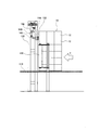
- FIG. 2 is a side view of a portion near the gate of the system of FIG. 1 as viewed from the side.
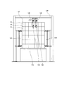
- FIG. 3 is a diagram illustrating one step of a method of integrating the package group according to the first embodiment.
- FIG. 4 is a diagram showing steps subsequent to FIG.
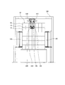
- FIG. 5 is a diagram showing a step following FIG.
- FIG. 6 is a partially enlarged view as seen from the direction of arrow 6A shown in FIG.
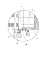
- FIG. 7 is a partially enlarged view showing a step following FIGS. 5 and 6.
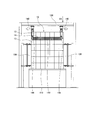
- FIG. 8 is a diagram showing steps subsequent to FIG.
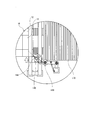
- FIG. 9 is a partially enlarged view showing a step following FIG. FIG.
- FIG. 10 is a partially enlarged view showing a step following FIG. 9.
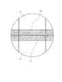
- FIG. 11 is a schematic diagram of a thermoplastic resin forming a connecting portion that connects the packages to each other.
- FIG. 12 is a schematic diagram illustrating a position of a connecting portion in the package group according to the second embodiment.
- FIG. 13 is a schematic diagram illustrating a position of a connecting portion in the package group according to the third embodiment.
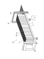
- FIG. 14 is a schematic diagram illustrating a position of a connecting portion in the package group according to the fourth embodiment.
- a method of integrating a group of packages having a plurality of packages according to one aspect is to form a connecting portion that connects the packages to each other by spraying a thermoplastic resin on portions where the packages are adjacent to each other.
- a connecting portion forming step is to form a connecting portion that connects the packages to each other by spraying a thermoplastic resin on portions where the packages are adjacent to each other.
- thermoplastic resin By spraying the thermoplastic resin, a connection portion is locally formed at a portion required for integrating the packages, so that a member (thermoplastic resin) necessary for integrating the packages is formed. The amount is kept to a minimum.
- the connecting portion for connecting the packages to each other is formed in a portion where the packages are adjacent to each other, the worker can visually check the connecting portion. Therefore, the worker can easily grasp the integrated state of the package group.
- the worker cannot visually recognize the surface to which the glue has adhered from the outside. Therefore, if the worker erroneously recognizes that the package groups are not connected to each other, the worker may pull one package from the package groups connected to each other when the package group is disassembled. . In this case, another package may be dragged by the pulled package, and the package group may collapse. In this aspect, since the worker can easily confirm the connecting portion visually, the possibility that the worker pulls the package in the state of being connected by mistake is reduced.
- thermoplastic resin is discharged from a nozzle that does not contact the package group.
- thermoplastic resin is discharged from the nozzle so as to form a net-like resin.
- thermoplastic resin Since the thermoplastic resin is discharged so as to form a net-like resin, the amount of the thermoplastic resin used can be reduced.
- thermoplastic resin forming the connecting portion has a net shape, the boundary between the packages can be visually recognized from the connecting portion. Therefore, the worker can visually confirm the state of formation of the connecting portion between the packages.
- At least one period of the connecting portion forming step is performed while the packages forming the package group are being loaded.
- the connecting portion forming step is performed while moving at least the package group.
- thermoplastic resin This allows the nozzle for spraying the thermoplastic resin to be moved at a minimum, thereby simplifying the apparatus for spraying the thermoplastic resin.
- package group can be integrated while the package group is transported to a required location.
- the package group includes a plurality of packages adjacent to each other in a height direction, and a plurality of packages adjacent to each other in a vertical direction intersecting the height direction.
- the packages constituting the package group are stacked in the height direction in the order from the first end on the stacking start side in the longitudinal direction to the second end on the stacking end in the vertical direction, and the first end
- the connecting portion that connects the packages adjacent to each other in the height direction is formed while stacking the packages closer to the second end than the first end.
- the connecting portion includes a first side of the stacking start side on a side surface in a horizontal direction intersecting the height direction and the vertical direction of the package group or an upper surface of the package group. It is formed from the end to the second end on the lamination end side.
- the connecting portion can be formed by relatively moving the nozzle for spraying the thermoplastic resin and the package body in one direction (longitudinal direction).
- the package group further includes a plurality of package bodies that are adjacent to each other in the horizontal direction that intersects with the height direction and the vertical direction, and the entire length of the package group in the vertical direction is Or the number of the packages arranged in the vertical direction is larger than the length of the entire package group in the horizontal direction, or the number of the packages arranged in the horizontal direction, and the connecting portion is at least the package It is formed on one end face in the lateral direction of the body group.
- the connecting portion is formed on the side surface where the length of the entire package group or the number of the package bodies is large, the entire package group can be more stably integrated.
- the connecting portion is formed at least on the uppermost package in the height direction.
- the connecting portion is formed at least on an upper surface of the package group in the height direction.
- the connecting portion is formed continuously over the packages adjacent to each other in at least one of the vertical direction and the horizontal direction.
- the connecting portions are formed continuously, the connecting portions are easily peeled off in one step, so that the disassembly of the package group becomes efficient.
- the connecting portion continuously extends from the package located at the first end on the lamination start side in the vertical direction to the package located at the second end on the lamination end side. It is formed.
- the entire package group can be firmly and stably integrated. Further, as described above, since the connecting portion is easily peeled off, the disassembly of the package group becomes efficient.
- FIG. 1 is a perspective view showing a schematic configuration of a system 100 for integrating a package group.
- FIG. 2 is a side view of a portion near the gate 120 of the system 100 of FIG.
- the package group 10 includes a plurality of packages 12 for storing articles.
- the package group 10 includes a plurality of package bodies 12 adjacent to each other in the height direction, a plurality of package bodies 12 adjacent to each other in the vertical direction intersecting in the height direction, and the horizontal direction intersecting in the height direction and the vertical direction. And a plurality of packing bodies 12 adjacent to each other.
- the vertical direction is a direction along the transport direction T of the package group 10 described later.
- the package 12 may be constituted by a paper box such as cardboard, for example, but is not limited thereto.
- the articles stored in each package 12 are not particularly limited. Such articles may be, for example, sanitary articles such as disposable diapers, napkins, masks.
- the system 100 for integrating the packages may include the conveyor 110, the gate 120, the pressing mechanism 130, and the coating device 140.
- the conveyor 110 may be configured to transport the package group 10 in the transport direction T while placing the package group 10.
- the end point 118 of the conveyor 110 may be configured to access a container of the vehicle, such as a trailer.
- the trailer may be parked on the conveyor 110 with the trailer container entrance facing the conveyor 110 at the end point 118 of the conveyor 110.
- the package group 10 conveyed by the conveyor 110 is accommodated in a container of a transporter such as a trailer.
- the gate 120 is provided near the conveyor 110.
- the package group 10 conveyed by the conveyor 110 passes through the gate 120 and reaches the final point 118.
- the gate 120 may be located near the moving package group 10.
- the pressing mechanism 130 is configured to press the side surface of the package group 10 being conveyed, specifically, one surface directed in a lateral direction orthogonal to the conveying direction T (see also FIG. 6).
- a pair of pressing mechanisms 130 may be provided on both sides of the conveyor 110. The pair of pressing mechanisms 130 presses both side surfaces of the package group 10 being transported, thereby suppressing collapse of the stacked state of the package group 10 and stably transporting the package group 10.
- Each pressing mechanism 130 may include an arm 131, a first rotation shaft 132 that supports the arm 131, and a pressing portion 134 provided at an end of the arm 131.
- the arm 131 is configured to be rotatable around the first rotation shaft 132, so that the pressing portion 134 can be pressed against the package group 10.
- the arm 131 may be urged by the damper 133 in the lateral direction perpendicular to the transport direction T so that the pressing portion 134 presses one side of the package group 10 on the conveyor 110.
- the damper 133 is configured to be able to absorb a force received from the outside. Therefore, the external force transmitted from the package group 10 to the arm 131 via the pressing portion 134 is absorbed by the damper 133. Thereby, the pressing portion 134 can press the package group 10 more stably.
- the pressing portion 134 may include a roller rotatable around the second rotation shaft 135.
- the second rotation shaft 135 may extend in a direction orthogonal to the conveying surface of the conveyor 110.
- the rollers constituting the pressing portion 134 are configured to be rotatable as the package group 10 is conveyed while being in contact with one side surface of the package group 10. Therefore, the roller constituting the pressing portion 134 can stably contact the package group 10 without rubbing against the package group 10.
- the coating device 140 may have a nozzle 148 for discharging the softened or melted thermoplastic resin 152.
- the thermoplastic resin 152 forms a connecting portion 150 that connects the packages 12 to each other by spraying the packages 12 on portions adjacent to each other. By connecting the packages 12 to each other, the package group 10 is stabilized.
- the nozzle 148 may be attached to the gate 120 via the arm 142.
- the arm 142 may be a movable arm configured to change the position and / or orientation of the nozzle 148. Thereby, the coating device 140 can discharge the thermoplastic resin 152 toward an appropriate position of the package group 10.
- the number of nozzles 148 for discharging the thermoplastic resin 152 is not particularly limited, but the coating device 140 preferably has at least two nozzles 148. In the first embodiment, the coating device 140 has two nozzles 148.
- the nozzle 148 does not contact the package group 10 while the thermoplastic resin 152 is being discharged. Thus, no force is applied to the package 12 from the nozzle 148 during ejection of the thermoplastic resin 152. Therefore, it is possible to prevent the loaded state of the package 12 from being damaged, and to integrate the package group 10 in a stable state.
- the method includes a package group forming step of stacking the packages 12 to form the above-described package group 10, and a connecting section forming step of forming a connecting section 150 that connects the packages 12 to each other. May be.
- a package group 10 including a plurality of packages 12 adjacent to each other in the height direction, the horizontal direction and the vertical direction is formed.
- the packages 12 may be stacked in the height direction in the order from the first end on the stacking start side to the second end on the stacking end side in the vertical direction. More specifically, the packing bodies 12 are stacked in the height direction from the downstream side in the transport direction T of the packing body group 10, and then the packing bodies 12 are further stacked at a position adjacent to the upstream side of the stacked packing bodies 12. What is necessary is just to laminate
- the connecting portions 150 connecting the packages 12 to each other are formed by spraying the thermoplastic resin 152 on portions where the packages 12 are adjacent to each other. More specifically, the connecting portion 150 formed of the thermoplastic resin 152 is formed over the adjacent packages 12. The thermoplastic resin 152 is sprayed in a softened or molten state on portions where the packages 12 are adjacent to each other, and is cured to form the connecting portion 150. As a result, the packages 12 adjacent to each other are fixed by the connecting portion 150.
- the connecting portion 150 can be locally formed at a position necessary for integrating the packages 12 by spraying the thermoplastic resin 152, members necessary for integrating the package group 10 are formed.
- the amount of (thermoplastic resin) is kept to a minimum.
- the connecting portions 150 for connecting the packages 12 to each other are formed at portions where the packages are adjacent to each other, the worker can visually check the connecting portions 150 from the outside. Therefore, the worker can easily grasp the integrated state of the package body group 10.
- thermoplastic resin 152 is discharged from the nozzle 148 so as to form a net-like resin, that is, a fibrous resin (see also FIG. 11).
- FIG. 11 is an enlarged view of the area A11 shown in FIG.
- the thermoplastic resin 152 forming the connecting portion 150 has a net shape.
- the usage amount of the thermoplastic resin 152 can be reduced.
- the thermoplastic resin forming the connecting portion 150 has a net shape, a boundary between the packing members 12 from the connecting portion 150 can be visually recognized. Therefore, the worker can visually confirm the state of formation of the connecting portion 150 between the packages.
- two nozzles 148 are arranged so as to face the downstream surface of the package group 10 in the transport direction T.
- the two nozzles 148 may discharge the thermoplastic resin 152 while moving in the same direction in a direction orthogonal to the transport direction T.
- the two nozzles 148 eject the thermoplastic resin 152 while moving in the opposite directions, that is, in the directions away from each other.
- the connecting portions 150 of the thermoplastic resin 152 are formed in the portions 14 where the packages 12 are adjacent to each other.
- thermoplastic resin 152 by discharging the thermoplastic resin 152 while the two nozzles 148 first move in the same direction (FIG. 3), a gap is not formed between the connecting portions 150 formed by the nozzles 148, and the connection is performed.
- the parts 150 can be formed continuously (see FIG. 4).
- the connecting portion 150 is formed on the downstream surface of the package group 10 in the transport direction T using two nozzles 148, but the downstream portion of the package group 10 in the transport direction T using one nozzle 148. May be formed with a connecting portion 150.
- the two nozzles 148 discharge the thermoplastic resin 152 while moving further away.
- the connecting portion 150 is formed up to the lateral end.
- the two nozzles 148 move to the outside of the lateral end of the package group 10 and discharge the thermoplastic resin 152 to the lateral side of the package group.
- the direction of the nozzle 148 is rotated around the rotation axis 149 so that it can be performed.
- only one nozzle 148 is shown in FIG. 6, the same applies to the other nozzle 148.
- thermoplastic resin 152 is discharged from the nozzle 148 so as to form the connection portion 150 between the adjacent packages 12 on the laterally facing side surfaces of the group of packages.
- the connecting portion 150 is provided on the side surface in the horizontal direction intersecting the height direction and the vertical direction of the package group, from the first end on the stacking start side of the package group 10 to the second end on the stacking end side. It is preferably formed toward the surface. That is, the connecting portion 150 is preferably formed along the transport direction T on the lateral side surface of the package body group 10. Specifically, the thermoplastic resin 152 is discharged from the nozzle 148 while moving the package group 10 in the transport direction T. Thereby, the connecting portion 150 is formed along the transport direction T of the package group 10 (see FIG. 8). In addition, it is preferable to form the connection part 150 by using two nozzles 148 on both sides of the package body group 10 facing in the lateral direction.
- the connecting portion 150 can be formed by relatively moving the nozzle 148 for spraying the thermoplastic resin 152 and the package body 10 in the transport direction (vertical direction) T.
- the nozzle 148 for spraying the thermoplastic resin 152 only needs to move at a minimum.
- the connecting portion 150 is formed on the laterally facing side surface of the package group 10
- the nozzle 148 does not need to move.
- the configuration of the coating device 140 that sprays the thermoplastic resin 152 can be simplified.
- the connecting portion forming step is performed while moving at least the package group 10, the package group 10 can be integrated while transporting the package group 10 to a required location (the final point 118).
- the advantage of being able to do so For example, when the entrance of the container of the trailer is connected to the end point 118 of the conveyor 110, the operation of integrating the package group 10 and the operation of loading the package group 10 on the trailer are performed at a stretch. Can be.
- At least one period of the connecting portion forming step be performed while the packages 12 constituting the package group 10 are being loaded. Accordingly, a connecting portion 150 described later can be formed between the packages 12 while the packages 12 are being stacked, so that the package group 10 can be prevented from collapsing during the stacking of the packages 12. . In addition, since both operations of stacking the packages 12 and connecting the packages 12 are performed at the same time, all the operations can be completed in a shorter period.
- the connecting portion 150 that connects the package 12 located at the downstream end in the transport direction T that is, the package 12 located at the first end on the stacking start side in the vertical direction, is closer to the first end. May also be formed while stacking the packages 12 on the second end side (downstream side). As described above, when the connecting portion 150 is formed between the already loaded packages 12 while the latter package (downstream package) 12 is loaded, the packages already loaded during the stacking of the latter package 12 are formed. The body 12 can be prevented from collapsing.
- the connecting portion 150 is formed on the laterally facing side surface of the package group 10 up to the downstream end of the package group 10 in the transport direction T, preferably the upstream side of the package group 10 in the transport direction T It is preferable that the connecting portion 150 is also formed on the surface of.
- the two nozzles 148 rotate around the rotation axis 149 again beyond the downstream end of the package group 10 in the transport direction T, and Can be discharged onto the surface of the package body 10 on the upstream side in the transport direction T.
- the connecting portion is also formed on the upstream surface in the transport direction T of the package group 10. 150 can be formed.
- thermoplastic resin 152 is preferably discharged from the nozzle 148 that does not contact the package group 10. Accordingly, no force is applied to the package 12 from the nozzle 148, so that the loaded state of the package 12 can be prevented from being damaged, and the package group 10 can be integrated in a stable state.
- the connecting portion 150 is formed at least on the uppermost package 12 in the height direction. More specifically, the connecting portion 150 is formed over the uppermost package 12 and the package 12 immediately below the uppermost package 12. In this case, since the connecting portion 150 is formed on the uppermost package 12 in the height direction in which the stability of the package group 10 is lowest, the stability of the entire package can be increased.
- the package 12 when sanitary articles such as disposable diapers, napkins and masks are densely packed in the package 12, the package 12 partially swells and the stability of the package group 10 may be reduced. . In such a situation, in particular, the stability of the uppermost package 12 is reduced. Therefore, it is particularly effective to form the connecting portion 150 on the uppermost package 12 in the height direction in which the stability of the package group 10 is lowest.
- the connecting portions 150 are locally formed in places where stability is low without connecting all the packages 12. Just doing it may be enough.
- the connecting portion 150 is formed continuously over the packaging bodies 12 adjacent to each other in at least one of the vertical direction and the horizontal direction.
- the connecting portion 150 is formed continuously in both the vertical direction (transport direction T) and the horizontal direction (see FIGS. 5 and 8). In this case, even if the connection between the packages 12 adjacent to each other is partially disconnected or weakened, the packages 12 adjacent to the connection portion 150 that has been disconnected or weakened are connected to each other. Sex can be maintained.
- the connecting portion 150 when the connecting portion 150 is formed continuously, the connecting portion 150 can be easily peeled off in one step, so that the packing body group 10 is efficiently disassembled.
- the connecting portion 150 is formed continuously from the package 12 located at the first end on the lamination start side in the vertical direction (transport direction T) to the package 12 located at the second end on the lamination end side.
- the connecting portion 150 is formed around the outer periphery of the package group 10 so as to draw a closed curve. Thereby, the whole package group 10 can be firmly and stably integrated. Further, in this case, as described above, since the connecting portion 150 is easily peeled off, the disassembly of the package group 10 is also efficient.
- the length of the entire package group 10 in the vertical direction (transport direction T) and / or the number of the package bodies 12 arranged in the vertical direction (transport direction T) are respectively equal to the package size in the horizontal direction. It may be larger than the entire length of the group 10 and / or the number of packages 12 arranged in the lateral direction. In this case, it is preferable that the connecting portion 150 is formed at least on one side surface of the package group 10 in the lateral direction. When the connecting portion 150 is formed on the side surface where the length of the entire package group 10 or the number of the package bodies 12 is large, the entire package group 10 can be more stably integrated.
- the connecting portion forming step is preferably performed while pressing the package group 10 from the side to the inside by the pressing mechanism 130 described above. Thereby, it is possible to prevent the packing body 12 from being broken during the connecting portion forming step.
- the conveyor 110 may convey the package group 10 to the final point 118.
- FIG. 12 is a schematic diagram showing the position of the connecting portion 150 in the package group 10 according to the second embodiment.
- the connecting portion 150 is formed at least on the upper surface of the package group 10 in the height direction from the first end on the stacking start side of the package 12 to the second end on the stacking end side. You.
- the connecting portion 150 is formed from the downstream side in the transport direction of the package group 10 to the upstream side.
- the connection part 150 may be formed over the packaging bodies 12 adjacent to each other in the lateral direction.
- the connecting portion 150 can be formed by discharging the thermoplastic resin 152 from the nozzle 148 while relatively moving the nozzle 148 and the package group 10. Note that the coating device 140 only needs to have the nozzles 148 as many as the connecting portions 150.
- the connecting portion 150 may extend continuously over the plurality of packages 12 in the transport direction T.
- the connecting portion 150 may extend continuously from the package 12 at the downstream end in the transport direction T to the package 12 at the upstream end.
- FIG. 13 is a schematic diagram showing the position of the connecting portion 150 in the package group 10 according to the third embodiment.
- the connecting portion 150 is formed intermittently on at least the uppermost package 12 in the height direction.
- the connection part 150 is formed in the uppermost package 12 over the packages 12 adjacent to each other in the horizontal direction and / or the vertical direction (transport direction T). Even if the connecting portion 150 is formed intermittently, the packages 12 can be connected to each other, so that the package group 10 can be stably integrated.
- the intermittent connecting portion 150 can be formed by intermittently discharging the thermoplastic resin 152 from the nozzle 148 while moving at least one of the nozzle 148 and the package group 10. If the connecting portion 150 is formed intermittently, the amount of the thermoplastic resin 152 used can be reduced.
- FIG. 14 is a schematic diagram showing a position of a thermoplastic resin as a connecting portion in the package group according to the fourth embodiment.
- the connecting portion 150 is intermittently formed at least on the uppermost package 12 in the height direction. Specifically, the connecting portion 150 extends over the uppermost package 12 and one lowermost package 12 at the top, and over the packages 12 adjacent to each other in the horizontal or vertical direction (transport direction T). It is formed. Even in this case, since the packages 12 can be connected to each other, the package group 10 can be stably integrated.
- both the uppermost package and the second package from the top can be connected with the same amount of the thermoplastic resin 152 used in the third embodiment.
Landscapes
- Engineering & Computer Science (AREA)
- Mechanical Engineering (AREA)
- Basic Packing Technique (AREA)
- Packages (AREA)
Abstract
複数の梱包体(12)を有する梱包体群(10)を一体化する方法は、梱包体(12)どうしが互いに隣接する部分に熱可塑性樹脂(152)を吹き付けることによって、梱包体(12)どうしを互いに連結する連結部(150)を形成する連結部形成工程を含む。
Description
本発明は、物品を梱包する複数の梱包体を有する梱包体群を一体化する方法に関する。
物品は、製造後に、例えば段ボールのような梱包物に収容され、輸送される。物品を梱包する複数の梱包体を輸送するため、複数の梱包体は、互いに積層された状態で搬送されることがある。この場合、複数の梱包体の積層状態がくずれたり、梱包体中の物品の破損を防止したりすることが必要となる。
特許文献1は、輸送中又は保管中において、瓦等の無機成形体の製品面に傷がつかず、割れや欠け等が発生しない無機成形体の梱包方法を開示する。具体的には、特許文献1に記載の方法は、無機成形体を梱包した梱包体を傾斜したパレット上にパレット面に垂直に積載する工程と、梱包体が積載されたパレット全体をフィルムで包装する工程と、を含む。
特許文献2は、梱包体を一体化する方法を開示する。この方法では、まず、包装体の上面に糊を噴出して糊面を形成する。それから、糊面が形成された包装体上に別の包装体を積層する。これにより、高さ方向に互いに隣接する包装体どうしが、糊によって互いに固定される。これにより、荷崩れの防止が図られている。
特許文献1では、複数の梱包体をパレットごとフィルムで包むことによって梱包物群が一体化されている。しかしながら、この方法では、梱包物群を一体化するために必要な部材(フィルム)が多くなる。また、複数の梱包体をパレットごとフィルムで包む必要があるため、作業効率が低く、また必要な装置も複雑及び/又は大型化することがある。
特許文献2に記載された方法では、梱包体の上面にのみ糊が形成されるため、高さ方向に互いに隣接する包装体どうししか固定することができない。また、糊が付着した面は、外側から視認できないため、作業員は梱包体の固定状態を把握することが困難である。
したがって、梱包体どうしを一体化するために必要な部材の量を最小限に留めつつ、梱包体群の一体化の状態(連結部の状態)を容易に把握することができる梱包体群を一体化する方法が望まれる。
複数の梱包体を有する梱包体群を一体化する方法は、前記梱包体どうしが互いに隣接する部分に熱可塑性樹脂を吹き付けることによって、前記梱包体どうしを互いに連結する連結部を形成する連結部形成工程を含む。
実施形態の概要
本明細書及び添付図面の記載により、少なくとも以下の事項が明らかとなる。
本明細書及び添付図面の記載により、少なくとも以下の事項が明らかとなる。
一態様に係る複数の梱包体を有する梱包体群を一体化する方法は、前記梱包体どうしが互いに隣接する部分に熱可塑性樹脂を吹き付けることによって、前記梱包体どうしを互いに連結する連結部を形成する連結部形成工程を含む。
熱可塑性樹脂の吹きつけによって、梱包体どうしを一体化するために必要な箇所に局所的に連結部が形成されるため、梱包体群を一体化するために必要な部材(熱可塑性樹脂)の量は必要最小限に留められる。
また、梱包体どうしを互いに連結する連結部は、梱包体どうしが互いに隣接する部分に形成されるため、作業員は、連結部を目視で確認することができる。したがって、作業員は、梱包体群の一体化の状態を容易に把握することができる。
例えば、特許文献2に記載された方法では、作業員は、糊が付着した面を外側から視認できない。したがって、梱包体群が互いに連結されていないと作業員が誤って認識した場合、作業員は、梱包体群の解体時に互いに連結された梱包体群から1つの梱包体を引っ張ってしまうことがある。この場合、引っ張られた梱包体に別の梱包体が引きずられ、梱包体群が崩れる可能性もある。本態様では、作業員は、連結部を目視で容易に確認することができるため、作業員が誤って連結された状態の梱包体を引っ張る虞が低減される。
好ましい一態様によれば、前記熱可塑性樹脂は、梱包体群に接触しないノズルから吐出される。
熱可塑性樹脂を吐出するノズルが梱包体に接触しないため、連結部の形成中にノズルから梱包体に力が加わらない。したがって、梱包体の積載状態が損なわれることを防止することができ、安定した状態で梱包体群を一体化することができる。
好ましい一態様によれば、前記熱可塑性樹脂は、網状の樹脂を形成するように前記ノズルから吐出される。
熱可塑性樹脂が、網状の樹脂を形成するように吐出されるため、熱可塑性樹脂の使用量を削減することができる。また、連結部を構成する熱可塑性樹脂が網状であるため、連結部から梱包体どうしの間の境界を視認することができる。したがって、作業員は、梱包体どうしの連結部の形成状態を目視で確認することができる。
好ましい一態様によれば、前記連結部形成工程の少なくとも一期間は、前記梱包体群を構成する前記梱包体を積載している間に行われる。
梱包体を積載しながら梱包体どうしの間に連結部を形成するため、梱包体の積層中に梱包体群が崩れることを防止することができる。また、梱包体の積層と梱包体どうしの連結の両作業が、同時期に行われるため、全作業をより短い期間で終了させることができる。
好ましい一態様によれば、連結部形成工程は、少なくとも前記梱包体群を移動させながら行われる。
これにより、熱可塑性樹脂を吹き付けるためのノズルは最小限可動すればよいため、熱可塑性樹脂を吹き付ける装置を簡素化できる。また、梱包体群を必要な箇所に向かって搬送しつつ梱包体群を一体化することができるという利点も得られる。
好ましい一態様によれば、前記梱包体群は、高さ方向に互いに隣接する複数の梱包体と、前記高さ方向に交差する縦方向に互いに隣接する複数の梱包体と、を有し、前記梱包体群を構成する前記梱包体は、前記縦方向における積層開始側の第1端部から積層終了側の第2端部に向かう順番で、前記高さ方向に積層され、前記第1端部において前記高さ方向に互いに隣接する前記梱包体どうしを連結する前記連結部は、前記第1端部よりも前記第2端部側における前記梱包体を積層している間に形成される。
後段の梱包体を積載しながら既に積載した梱包体どうしの間に連結部を形成するため、後段の梱包体の積層中に既に積載した梱包体が崩れることを防止することができる。
好ましい一態様によれば、前記連結部は、前記梱包体群の、前記高さ方向及び前記縦方向に交差する横方向における側面、又は前記梱包体群の上面に、前記積層開始側の第1端部から前記積層終了側の第2端部に向って形成される。
熱可塑性樹脂を吹き付けるためのノズルと梱包体群とを一方向(縦方向)に相対移動させることによって、連結部を形成することができる。これにより、梱包体群を一体化する方法を単純化することができ、梱包体群を一体化するために必要な装置を簡素化することができる。
好ましい一態様によれば、前記梱包体群は、前記高さ方向及び前記縦方向に交差する横方向に互いに隣接する複数の梱包体をさらに有し、前記縦方向における前記梱包体群全体の長さ、又は前記縦方向に並ぶ前記梱包体数は、前記横方向における前記梱包体群全体の長さ、又は前記横方向に並ぶ前記梱包体数よりも大きく、前記連結部は、少なくとも、前記梱包体群の前記横方向における一端面に形成される。
梱包体群全体の長さ、又は梱包体の数が大きい側面に連結部が形成されるため、梱包物群全体をより安定的に一体化することができる。
好ましい一態様によれば、前記連結部は、少なくとも前記高さ方向における最上部の前記梱包体に形成される。
最も安定性が低くなる高さ方向における最上部の梱包体に連結部が形成されるため、梱包体全体の安定性を高めることができる。
好ましい一態様によれば、前記連結部は、少なくとも前記高さ方向における前記梱包体群の上面に形成される。
最も安定性が低くなる高さ方向における最上部の梱包体に連結部が形成されるため、梱包体全体の安定性を高めることができる。
好ましい一態様によれば、前記連結部は、前記縦方向と前記横方向のうちの少なくとも一方の方向において互いに隣接する前記梱包体にわたって連続的に形成される。
これにより、一部において互いに隣接する梱包体どうしの連結が外れ又は弱まったとしても、外れ又は弱まった連結部に隣接する梱包体どうしが連結されているため、梱包体群の安定性を維持することができる。
また、連結部が連続的に形成されていると、一ステップで連結部を剥がし易いため、梱包体群の解体が効率的になる。
好ましい一態様によれば、前記連結部は、前記縦方向における積層開始側の第1端部に位置する前記梱包体から、積層終了側の第2端部に位置する前記梱包体まで連続的に形成される。
これにより、梱包体群全体をしっかりと安定的に一体化することができる。さらに、前述したように連結部を剥がし易いため、梱包体群の解体が効率的になる。
(2)第1実施形態
以下、図面を参照して、第1実施形態に係る吸収性物品について説明する。なお、以下の図面の記載において、同一又は類似の部分には、同一又は類似の符号を付している。ただし、図面は模式的なものであり、各寸法の比率等は現実のものとは異なることに留意すべきである。したがって、具体的な寸法等は、以下の説明を参酌して判断すべきである。また、図面相互間においても互いの寸法の関係や比率が異なる部分が含まれ得る。
以下、図面を参照して、第1実施形態に係る吸収性物品について説明する。なお、以下の図面の記載において、同一又は類似の部分には、同一又は類似の符号を付している。ただし、図面は模式的なものであり、各寸法の比率等は現実のものとは異なることに留意すべきである。したがって、具体的な寸法等は、以下の説明を参酌して判断すべきである。また、図面相互間においても互いの寸法の関係や比率が異なる部分が含まれ得る。
図1は、梱包体群を一体化するシステム100の概略的構成を示す斜視図である。図2は、図1のシステム100のゲート120付近の部分を側方から見た側面図である。梱包体群10は、物品を収容する複数の梱包体12を含む。梱包体群10は、高さ方向に互いに隣接する複数の梱包体12と、高さ方向に交差する縦方向に互いに隣接する複数の梱包体12と、高さ方向及び縦方向に交差する横方向に互いに隣接する複数の梱包体12と、を有していてよい。ここで、縦方向は、後述する梱包体群10の搬送方向Tに沿った方向である。
梱包体12は、例えばダンボールのような紙製の箱によって構成されていてもよいが、これに限定されるものではない。各々の梱包体12内に収容される物品は、特に限定されるものではない。そのような物品は、例えば、使い捨ておむつ、ナプキン、マスクのような衛材物品であってもよい。
梱包体群を一体化するシステム100は、コンベア110と、ゲート120と、押圧機構130と、塗布装置140と、を有していてよい。コンベア110は、梱包体群10を載せつつ、梱包体群10を搬送方向Tに搬送するよう構成されていてよい。コンベア110の最終地点118は、トレーラのような輸送体のコンテナにアクセス可能に構成されていてもよい。例えば、トレーラは、コンベア110の最終地点118のところでトレーラのコンテナの入口をコンベア110側に向けて、コンベア110に接車可能になっていてよい。この場合、コンベア110によって搬送された梱包体群10は、トレーラのような輸送体のコンテナ内に収容されることになる。
ゲート120は、コンベア110に近接して設けられている。コンベア110で搬送される梱包体群10は、ゲート120を通過して最終地点118まで到達する。ゲート120は、移動中の梱包体群10の近くに位置していればよい。
押圧機構130は、搬送中の梱包体群10の側面、具体的には搬送方向Tに直交する横方向に向けられる一面を押圧するよう構成されている(図6も参照)。押圧機構130は、コンベア110の両側に一対設けられていてよい。一対の押圧機構130が、搬送中の梱包体群10の両側面を押圧することによって、梱包体群10の積層状態のくずれを抑制し、安定的に梱包体群10を搬送することができる。
各々の押圧機構130は、アーム131と、アーム131を支持する第1回転軸132と、アーム131の端部に設けられた押圧部134と、を有していてよい。アーム131は、第1回転軸132まわりに回動可能に構成されており、これにより押圧部134を梱包体群10に押圧させることができる。
より具体的には、アーム131は、押圧部134がコンベア110上の梱包体群10の一側面に押圧するよう、ダンパー133によって搬送方向Tに直交する横方向へ付勢されていてよい。ダンパー133は、外部から受けた力を吸収可能に構成されている。したがって、梱包体群10から押圧部134を介してアーム131に伝わった外力は、ダンパー133によって吸収される。これにより、押圧部134は、梱包体群10をより安定的に押圧することができる。
押圧部134は、第2回転軸135まわりに回転可能なローラを備えていてよい。第2回転軸135は、コンベア110の搬送面に直交する方向に延びていてよい。これにより、押圧部134を構成するローラは、梱包体群10の一側面に当接した状態で、梱包体群10の搬送に伴って回転可能に構成される。したがって、押圧部134を構成するローラは、梱包体群10に擦れることなく、安定的に梱包体群10に当接することができる。
塗布装置140は、軟化又は溶融させた熱可塑性樹脂152を吐出するノズル148を有していてよい。熱可塑性樹脂152は、梱包体12どうしが互いに隣接する部分に吹き付けられることで、梱包体12どうしを互いに連結する連結部150を形成する。梱包体12どうしが互いに連結されることで、梱包体群10が安定することになる。
ノズル148は、アーム142を介してゲート120に取り付けられていてよい。アーム142は、ノズル148の位置及び/又は向きを可変にするよう構成された可動アームであってよい。これにより、塗布装置140は、梱包体群10の適切な位置に向けて熱可塑性樹脂152を吐出することができる。
熱可塑性樹脂152を吐出するノズル148の数は特に制限されないが、塗布装置140は、少なくとも2つのノズル148を有することが好ましい。第1実施形態では、塗布装置140は、2つのノズル148を有している。
ノズル148は、熱可塑性樹脂152の吐出中に梱包体群10に接触しないことが好ましい。これにより、熱可塑性樹脂152の吐出中に、ノズル148から梱包体12に力が加わらない。したがって、梱包体12の積載状態が損なわれることを防止することができ、安定した状態で梱包体群10を一体化することができる。
次に、図3~図11を参照しつつ、第1実施形態に係る梱包体群を一体化する方法について説明する。この方法は、梱包体12を集積させて前述した梱包体群10を形成する梱包体群形成工程と、梱包体12どうしを互いに連結する連結部150を形成する連結部形成工程と、を含んでいてよい。
梱包体群形成工程では、高さ方向、横方向及び縦方向に互いに隣接する複数の梱包体12を含む梱包体群10が形成される。梱包体12は、縦方向における積層開始側の第1端部から積層終了側の第2端部に向かう順番で、高さ方向に積層されてよい。より具体的には、梱包体群10の搬送方向Tの下流側から梱包体12を高さ方向に積層し、それから、積層された梱包体12の上流側に隣接する位置でさらに梱包体12を高さ方向に積層すればよい。この場合、梱包体群10の形成中であっても、梱包体12を高さ方向に積層し終えた部分について、後述する連結部形成工程を行うことができる。
連結部形成工程では、梱包体12どうしが互いに隣接する部分に熱可塑性樹脂152を吹き付けることによって、梱包体12どうしを互いに連結する連結部150を形成する。より具体的には、熱可塑性樹脂152により形成される連結部150は、互いに隣接する梱包体12にわたって形成される。熱可塑性樹脂152は、軟化又は溶融状態で梱包体12どうしが互いに隣接する部分に吹き付けられ、硬化することにより連結部150を形成する。これにより、互いに隣接する梱包体12どうしが、連結部150により固定されることになる。
熱可塑性樹脂152の吹きつけによって、梱包体12どうしを一体化するために必要な箇所に局所的に連結部150を形成することができるため、梱包体群10を一体化するために必要な部材(熱可塑性樹脂)の量は必要最小限に留められる。
また、梱包体12どうしを互いに連結する連結部150は、梱包体どうしが互いに隣接する部分に形成されるため、作業員は、連結部150を外部から目視で確認することができる。したがって、作業員は、梱包体群10の一体化の状態を容易に把握することができる。
熱可塑性樹脂152は、網状の樹脂、すなわち繊維状の樹脂を形成するようにノズル148から吐出されることが好ましい(図11も参照)。なお、図11は、図8に示す領域A11の拡大図である。これにより、図11に示すように、連結部150を構成する熱可塑性樹脂152が網状になる。これにより、熱可塑性樹脂152の使用量を削減することができる。また、連結部150を構成する熱可塑性樹脂が網状であるため、連結部150から梱包体12どうしの間の境界を視認することができる。したがって、作業員は、梱包体どうしの連結部150の形成状態を目視で確認することができる。
次に、連結部形成工程の具体的な手順の一例について詳細に説明する。まず、必要に応じて、図3に示すように、梱包体群10の搬送方向Tの下流側の面に対向して2つのノズル148を配置させる。2つのノズル148は、搬送方向Tに直交する方向に互いに同方向に移動しつつ、熱可塑性樹脂152を吐出してよい。それから、図4に示すように、2つのノズル148は、互いに逆の方向、すなわち互いに離れる方向に移動しつつ、熱可塑性樹脂152を吐出する。これにより、梱包体12どうしが互いに隣接する部分14に熱可塑性樹脂152による連結部150を形成する。ここで、2つのノズル148が始めに同方向に移動しつつ熱可塑性樹脂152を吐出することで(図3)、各ノズル148によって形成される連結部150どうしの間に隙間ができず、連結部150どうしが連続的に形成され得る(図4参照)。
ここでは、2つのノズル148を用いて梱包体群10の搬送方向Tの下流側の面に連結部150を形成したが、1つのノズル148を用いて梱包体群10の搬送方向Tの下流側の面に連結部150を形成してもよい。
次に、図5及び図6に示すように、2つのノズル148は、さらに離れる方向に移動しつつ、熱可塑性樹脂152を吐出する。これにより、梱包体群10の搬送方向Tの下流側の面において、横方向の端部まで連結部150が形成される。
次に、図7に示すように、2つのノズル148は、梱包体群10の横方向の端部よりも外側まで移動し、熱可塑性樹脂152を梱包体群の横方向に向いた側面に吐出できるようノズル148の向きを回転軸149まわりに回転させる。なお、図6では、一方のノズル148しか示されていないが、他方のノズル148についても同様である。
次に、梱包体群の横方向に向いた側面において、互いに隣接する梱包体12どうしにわたって連結部150を形成するよう、ノズル148から熱可塑性樹脂152を吐出する。
連結部150は、前記梱包体群の、高さ方向及び前記縦方向に交差する横方向における側面に、梱包体群10の積層開始側の第1端部から積層終了側の第2端部に向かって形成されることが好ましい。すなわち、連結部150は、梱包体群10の横方向における側面において、搬送方向Tに沿って形成されることが好ましい。具体的には、梱包体群10を搬送方向Tに移動させながら、ノズル148から熱可塑性樹脂152を吐出する。これにより、梱包体群10の搬送方向Tに沿って、連結部150が形成される(図8参照)。なお、2つのノズル148を用いて、梱包体群10の横方向に向いた両側面に、連結部150を形成することが好ましい。
熱可塑性樹脂152を吹き付けるためのノズル148と梱包体群10とを搬送方向(縦方向)Tに相対移動させることによって、連結部150を形成することができる。これにより、梱包体群を一体化する方法を単純化することができ、梱包体群を一体化するために必要なシステム100を簡素化することができる。
また、連結部形成工程が、少なくとも梱包体群10を移動させながら行われることにより、熱可塑性樹脂152を吹き付けるためのノズル148は最小限可動すればよい。例えば、梱包体群10の横方向に向いた側面に連結部150を形成する場合、ノズル148は移動する必要がなくなる。この場合、熱可塑性樹脂152を吹き付ける塗布装置140の構成を簡素化できる。
また、連結部形成工程が少なくとも梱包体群10を移動させながら行われることにより、梱包体群10を必要な箇所(最終地点118)に向かって搬送しつつ梱包体群10を一体化することができるという利点も得られる。例えば、コンベア110の最終地点118のところにトレーラのコンテナの入口が連結されている場合には、梱包体群10を一体化する作業と、トレーラに梱包体群10を積み込む作業とを一気に行うことができる。
連結部形成工程の少なくとも一期間は、梱包体群10を構成する梱包体12を積載している間に行われることが好ましい。これにより、梱包体12を積載しながら梱包体12どうしの間に後述する連結部150を形成することができるため、梱包体12の積層中に梱包体群10が崩れることを防止することができる。また、梱包体12の積層と梱包体12どうしの連結の両作業が、同時期に行われるため、全作業をより短い期間で終了させることができる。
例えば、搬送方向Tの下流側の端部に位置する梱包体12、すなわち縦方向における積層開始側の第1端部に位置する梱包体12を連結する連結部150は、当該第1端部よりも第2端部側(下流側)における梱包体12を積層している間に形成されてもよい。このように、後段の梱包体(下流側の梱包体)12を積載しながら既に積載した梱包体12どうしの間に連結部150を形成すると、後段の梱包体12の積層中に既に積載した梱包体12が崩れることを防止することができる。
梱包体群10の横方向に向いた側面について、搬送方向Tにおける梱包体群10の下流側の端部まで連結部150が形成されたら、好ましくは、梱包体群10の搬送方向Tにおける上流側の面にも連結部150を形成することが好ましい。
具体的には、図9に示すように、2つのノズル148は、搬送方向Tにおける梱包体群10の下流側の端部を超えたところで、回転軸149まわりに再び回転し、熱可塑性樹脂152を梱包体群10の搬送方向Tにおける上流側の面に吐出できるようにする。この状態で、2つのノズル148どうしが互いに近づくように移動しつつ、2つのノズル148から熱可塑性樹脂152を吐出することで、梱包体群10の搬送方向Tにおける上流側の面にも連結部150を形成することができる。
2つのノズル148が互いに近接したら、熱可塑性樹脂152を吐出しながら2つのノズル148を同方向に移動させることにより、各ノズル148によって形成される連結部150どうしが連続的に繋がることになる。
上記の連結部形成工程において、熱可塑性樹脂152は、梱包体群10に接触しないノズル148から吐出されることが好ましい。これにより、ノズル148から梱包体12に力が加わらないので、梱包体12の積載状態が損なわれることを防止することができ、安定した状態で梱包体群10を一体化することができる。
第1実施形態では、連結部150は、少なくとも高さ方向における最上部の梱包体12に形成される。より具体的には、連結部150は、最上部の梱包体12と、最上部の梱包体12の1つ下側の梱包体12とにわたって形成される。この場合、梱包体群10の安定性が最も低くなる高さ方向における最上部の梱包体12に連結部150が形成されるため、梱包体全体の安定性を高めることができる。
特に、使い捨ておむつ、ナプキン、マスクのような衛材物品が梱包体12中に密に詰め込まれている場合、梱包体12が部分的に膨らみ、梱包体群10の安定性が低下することがある。このような状況では、特に最上部の梱包体12の安定性が低下する。したがって、梱包体群10の安定性が最も低くなる高さ方向における最上部の梱包体12に連結部150が形成すると特に効果的である。なお、使い捨ておむつ、ナプキン、マスクのような衛材物品は、比較的重量が小さいため、すべての梱包体12を連結させなくても、安定性の低くなる箇所において局所的に連結部150を形成するだけで十分となり得る。
また、連結部150は、縦方向と横方向のうちの少なくとも一方の方向において互いに隣接する梱包体12にわたって連続的に形成されることが好ましい。第1実施形態では、連結部150は、縦方向(搬送方向T)においても、横方向においても、連続的に形成されている(図5及び図8参照)。この場合、一部において互いに隣接する梱包体12どうしの連結が外れ又は弱まったとしても、外れ又は弱まった連結部150に隣接する梱包体12どうしが連結されているため、梱包体群10の安定性を維持することができる。また、連結部150が連続的に形成されていると、一ステップで連結部150を剥がし易いため、梱包体群10の解体が効率的になる。
さらに、連結部150は、縦方向(搬送方向T)における積層開始側の第1端部に位置する梱包体12から、積層終了側の第2端部に位置する梱包体12まで連続的に形成されることが好ましい。より好ましくは、連結部150は、閉曲線を描くよう、梱包体群10の外周に一周形成される。これにより、梱包体群10全体をしっかりと安定的に一体化することができる。さらに、この場合、前述したように連結部150を剥がし易いため、梱包体群10の解体も効率的である。
図8に示すように、縦方向(搬送方向T)における梱包体群10全体の長さ、及び/又は縦方向(搬送方向T)に並ぶ梱包体12の数は、それぞれ、横方向における梱包体群10全体の長さ、及び/又は横方向に並ぶ梱包体12の数よりも大きくてよい。この場合、連結部150は、少なくとも、梱包体群10の横方向における一側面に形成されることが好ましい。梱包体群10全体の長さ、又は梱包体12の数が大きい側面に連結部150が形成されると、梱包体群10全体をより安定的に一体化することができる。
なお、連結部形成工程は、前述した押圧機構130により、梱包体群10を横方向から内側へ押圧しつつ実施されることが好ましい。これにより、連結部形成工程中に梱包体12がくずれることを抑制することができる。
連結部形成工程が終了すると、コンベア110は、梱包体群10を最終地点118まで搬送すればよい。
(3)第2実施形態
次に、第2実施形態について説明する。第2実施形態において、第1実施形態と同様の構成については、同様の符号が付されている。以下では、第1実施形態と同様の構成については、その説明を省略する。第2実施形態では、梱包体群10に形成される連結部150の位置が、第1実施形態と異なっている。
次に、第2実施形態について説明する。第2実施形態において、第1実施形態と同様の構成については、同様の符号が付されている。以下では、第1実施形態と同様の構成については、その説明を省略する。第2実施形態では、梱包体群10に形成される連結部150の位置が、第1実施形態と異なっている。
図12は、第2実施形態に係る梱包体群10において連結部150の位置を示す模式図である。第2実施形態では、連結部150は、少なくとも高さ方向における梱包体群10の上面に、梱包体12の積層開始側の第1端部から積層終了側の第2端部に向って形成される。言い換えると、連結部150は、梱包体群10の搬送方向の下流側から上流側に向かって形成される。この場合、連結部150は、横方向に互いに隣接する梱包体12どうしにわたって形成されていてよい。この場合であっても、ノズル148と梱包体群10とを相対移動させながら、ノズル148から熱可塑性樹脂152を吐出することによって連結部150を形成することができる。なお、塗布装置140は、連結部150の本数だけノズル148を有していればよい。
また、最も安定性が低くなる高さ方向における最上部の梱包体12に連結部150が形成されるため、梱包体12全体の安定性を高めることができる。
第1実施形態と同様に、梱包体群10の安定性と連結部150の剥がし易さという観点では、連結部150は、搬送方向Tに複数の梱包体12にわたって連続的に延びていることが好ましい。より好ましくは、連結部150は、搬送方向Tの下流側の端部の梱包体12から上流側の端部の梱包体12まで連続的に延びていてよい。
(4)第3実施形態
次に、第3実施形態について説明する。第3実施形態において、第1実施形態と同様の構成については、同様の符号が付されている。以下では、第1実施形態と同様の構成については、その説明を省略することがある。第3実施形態では、梱包体群10に形成される連結部150の位置が、第1実施形態と異なっている。
次に、第3実施形態について説明する。第3実施形態において、第1実施形態と同様の構成については、同様の符号が付されている。以下では、第1実施形態と同様の構成については、その説明を省略することがある。第3実施形態では、梱包体群10に形成される連結部150の位置が、第1実施形態と異なっている。
図13は、第3実施形態に係る梱包体群10において連結部150の位置を示す模式図である。第3実施形態では、連結部150は、少なくとも高さ方向における最上部の梱包体12に間欠的に形成されている。具体的には、連結部150は、最上部の梱包体12において、横方向及び/又は縦方向(搬送方向T)に互いに隣接する梱包体12にわたって形成される。連結部150が間欠的に形成されている場合であっても、梱包体12同士を連結させることができるため、梱包体群10を安定的に一体化させることができる。なお、間欠的な連結部150は、ノズル148及び梱包体群10の少なくとも一方を移動させつつ、ノズル148から熱可塑性樹脂152を間欠的に吐出することによって形成することができる。連結部150を間欠的に形成すれば、熱可塑性樹脂152の使用量を削減することができる。
(5)第4実施形態
次に、第4実施形態について説明する。第4実施形態において、第1実施形態と同様の構成については、同様の符号が付されている。以下では、第1実施形態と同様の構成については、その説明を省略することがある。第4実施形態では、梱包体群10に形成される連結部150の位置が、第1実施形態と異なっている。
次に、第4実施形態について説明する。第4実施形態において、第1実施形態と同様の構成については、同様の符号が付されている。以下では、第1実施形態と同様の構成については、その説明を省略することがある。第4実施形態では、梱包体群10に形成される連結部150の位置が、第1実施形態と異なっている。
図14は、第4実施形態に係る梱包体群において連結部として熱可塑性樹脂の位置を示す模式図である。第4実施形態では、連結部150は、少なくとも高さ方向における最上部の梱包体12に間欠的に形成されている。具体的には、連結部150は、最上部の梱包体12と最上部の1つの下側の梱包体12とにわたり、且つ横方向又は縦方向(搬送方向T)に互いに隣接する梱包体12にわたって形成される。この場合であっても、梱包体12同士を連結させることができるため、梱包体群10を安定的に一体化させることができる。第4実施形態では、第3実施形態と同程度の熱可塑性樹脂152の使用量で、最上段と上から2段目の両方の梱包体12を連結させることができる。
以上、上述の実施形態を用いて本発明について詳細に説明したが、当業者にとっては、本発明が本明細書中に説明した実施形態に限定されるものではないということは明らかである。本発明は、特許請求の範囲の記載により定まる本発明の趣旨及び範囲を逸脱することなく修正及び変更態様として実施することができる。したがって、本明細書の記載は、例示説明を目的とするものであり、本発明に対して何ら制限的な意味を有するものではない。
なお、日本国特許出願第2018-122806号(2018年6月28日出願)の全内容が、参照により、本願明細書に組み込まれている。
10 梱包体群
12 梱包体
100 システム
110 コンベア
118 最終地点
120 ゲート
130 押圧機構
131 アーム
132 第1回転軸
133 ダンパー
134 押圧部
135 第2回転軸
140 塗布装置
142 アーム
148 ノズル
149 回転軸
150 連結部
152 熱可塑性樹脂
12 梱包体
100 システム
110 コンベア
118 最終地点
120 ゲート
130 押圧機構
131 アーム
132 第1回転軸
133 ダンパー
134 押圧部
135 第2回転軸
140 塗布装置
142 アーム
148 ノズル
149 回転軸
150 連結部
152 熱可塑性樹脂
Claims (12)
- 複数の梱包体を有する梱包体群を一体化する方法であって、
前記梱包体どうしが互いに隣接する部分に熱可塑性樹脂を吹き付けることによって、前記梱包体どうしを互いに連結する連結部を形成する連結部形成工程を含む、梱包体群を一体化する方法。 - 前記熱可塑性樹脂は、梱包体群に接触しないノズルから吐出される、請求項1に記載の梱包体群を一体化する方法。
- 前記熱可塑性樹脂は、網状の樹脂を形成するように前記ノズルから吐出される、請求項2に記載の梱包体群を一体化する方法。
- 前記連結部形成工程の少なくとも一期間は、前記梱包体群を構成する前記梱包体を積載している間に行われる、請求項1に記載の梱包体群を一体化する方法。
- 前記連結部形成工程は、少なくとも前記梱包体群を移動させながら行われる、請求項1から4のいずれか1項に記載の梱包体群を一体化する方法。
- 前記梱包体群は、高さ方向に互いに隣接する複数の梱包体と、前記高さ方向に交差する縦方向に互いに隣接する複数の梱包体と、を有し、
前記梱包体群を構成する前記梱包体は、前記縦方向における積層開始側の第1端部から積層終了側の第2端部に向かう順番で、前記高さ方向に積層され、
前記第1端部において前記高さ方向に互いに隣接する前記梱包体どうしを連結する前記連結部は、前記第1端部よりも前記第2端部側における前記梱包体を積層している間に形成される、請求項1から5のいずれか1項に記載の梱包体群を一体化する方法。 - 前記連結部は、前記梱包体群の、前記高さ方向及び前記縦方向に交差する横方向における側面、又は前記梱包体群の上面に、前記積層開始側の第1端部から前記積層終了側の第2端部に向って形成される、請求項6に記載の梱包体群を一体化する方法。
- 前記梱包体群は、前記高さ方向及び前記縦方向に交差する横方向に互いに隣接する複数の梱包体をさらに有し、
前記縦方向における前記梱包体群全体の長さ、又は前記縦方向に並ぶ前記梱包体数は、前記横方向における前記梱包体群全体の長さ、又は前記横方向に並ぶ前記梱包体数よりも大きく、
前記連結部は、少なくとも、前記梱包体群の前記横方向における一端面に形成される、請求項6又は7に記載の梱包体群を一体化する方法。 - 前記連結部は、少なくとも前記高さ方向における最上部の前記梱包体に形成される、請求項6から8のいずれか1項に記載の梱包体群を一体化する方法。
- 前記連結部は、少なくとも前記高さ方向における前記梱包体群の上面に形成される、請求項7又は8に記載の梱包体群を一体化する方法。
- 前記連結部は、前記縦方向と前記横方向のうちの少なくとも一方の方向において互いに隣接する前記梱包体にわたって連続的に形成される、請求項6から10のいずれか1項に記載の梱包体群を一体化する方法。
- 前記連結部は、前記縦方向における積層開始側の第1端部に位置する前記梱包体から、積層終了側の第2端部に位置する前記梱包体まで連続的に形成される、請求項6から11のいずれか1項に記載の梱包体群を一体化する方法。
Applications Claiming Priority (2)
| Application Number | Priority Date | Filing Date | Title |
|---|---|---|---|
| JP2018-122806 | 2018-06-28 | ||
| JP2018122806A JP6790028B2 (ja) | 2018-06-28 | 2018-06-28 | 梱包体群を一体化する方法 |
Publications (1)
| Publication Number | Publication Date |
|---|---|
| WO2020004584A1 true WO2020004584A1 (ja) | 2020-01-02 |
Family
ID=68984913
Family Applications (1)
| Application Number | Title | Priority Date | Filing Date |
|---|---|---|---|
| PCT/JP2019/025702 Ceased WO2020004584A1 (ja) | 2018-06-28 | 2019-06-27 | 梱包体群を一体化する方法 |
Country Status (2)
| Country | Link |
|---|---|
| JP (1) | JP6790028B2 (ja) |
| WO (1) | WO2020004584A1 (ja) |
Citations (4)
| Publication number | Priority date | Publication date | Assignee | Title |
|---|---|---|---|---|
| JPS4858998A (ja) * | 1971-11-15 | 1973-08-18 | ||
| JPH05170217A (ja) * | 1991-12-17 | 1993-07-09 | Sutorapatsuku Kk | 梱包機におけるバンド供給装置 |
| JPH05338615A (ja) * | 1992-06-10 | 1993-12-21 | Sutorapatsuku Kk | 梱包機におけるバンド供給・引締方法及び装置 |
| JP2002114208A (ja) * | 2000-07-31 | 2002-04-16 | Strapack Corp | 梱包機のバンド供給装置およびバンド供給方法 |
-
2018
- 2018-06-28 JP JP2018122806A patent/JP6790028B2/ja not_active Expired - Fee Related
-
2019
- 2019-06-27 WO PCT/JP2019/025702 patent/WO2020004584A1/ja not_active Ceased
Patent Citations (4)
| Publication number | Priority date | Publication date | Assignee | Title |
|---|---|---|---|---|
| JPS4858998A (ja) * | 1971-11-15 | 1973-08-18 | ||
| JPH05170217A (ja) * | 1991-12-17 | 1993-07-09 | Sutorapatsuku Kk | 梱包機におけるバンド供給装置 |
| JPH05338615A (ja) * | 1992-06-10 | 1993-12-21 | Sutorapatsuku Kk | 梱包機におけるバンド供給・引締方法及び装置 |
| JP2002114208A (ja) * | 2000-07-31 | 2002-04-16 | Strapack Corp | 梱包機のバンド供給装置およびバンド供給方法 |
Also Published As
| Publication number | Publication date |
|---|---|
| JP2020001752A (ja) | 2020-01-09 |
| JP6790028B2 (ja) | 2020-11-25 |
Similar Documents
| Publication | Publication Date | Title |
|---|---|---|
| CN102020026B (zh) | 用于形成包装体的方法和装置 | |
| CN101804870B (zh) | 装箱装置 | |
| US11884434B2 (en) | Packaging machine and method for producing a packaging unit as well as a packaging unit made of packaging sleeves and an outer packaging | |
| CN102448828B (zh) | 用于将产品包装到对应容器的设备 | |
| JP5542189B2 (ja) | パウチ型飲料容器を包装するためのカートン、包装体を閉鎖するための装置、及び、包装体を閉鎖するための方法 | |
| US6742459B2 (en) | System and method for producing a disposable/recyclable pallet | |
| JPH01308708A (ja) | ストレッチラッピングを行うロボットパレタイザ | |
| KR102462448B1 (ko) | 멀티 박스제조 시스템 | |
| CN102358445A (zh) | 在物品堆周围包裹薄膜的设备和方法 | |
| CN113272228A (zh) | 用于将薄膜包装在物品周围的包装机 | |
| TWI523798B (zh) | A rectangular parallelepiped package, a manufacturing method thereof, a manufacturing apparatus, a container for a rectangular parallelepiped package, and a storage method | |
| CN100503376C (zh) | 处理和加工用于包装烟草制品的坯料的方法和装置 | |
| WO2020004584A1 (ja) | 梱包体群を一体化する方法 | |
| CN108609241B (zh) | 鼓式汽车刹车片自动化包装系统及方法 | |
| KR102249098B1 (ko) | 친환경 양면코팅 종이 상자 제작장치 및 이를 이용한 친환경 양면코팅 종이 상자 제작방법 | |
| JPH07223613A (ja) | 箱製函装置 | |
| JP6985860B2 (ja) | 容器入りフェイスマスクの製造装置及び容器入りフェイスマスクの製造方法 | |
| US20210031479A1 (en) | Device and method for applying a protective element to a packaging | |
| KR20210023566A (ko) | 친환경 양면코팅 종이 상자 제작방법 및 이를 이용한 친환경 양면코팅 종이 상자 | |
| ITMO20070145A1 (it) | "procedimento ed impianto per la fasciatura di carichi pallettizzati" | |
| JP5707458B2 (ja) | 吸収性物品を有する物品の整列搬送方法、及び整列搬送装置 | |
| JP2019172287A (ja) | 包装装置及び包装体 | |
| JP2003200904A (ja) | 梱包装置 | |
| CN119218511B (zh) | 一种基于包装箱运输的输送机系统 | |
| CN107406181A (zh) | 搬运用卷膜捆包体 |
Legal Events
| Date | Code | Title | Description |
|---|---|---|---|
| 121 | Ep: the epo has been informed by wipo that ep was designated in this application |
Ref document number: 19824628 Country of ref document: EP Kind code of ref document: A1 |
|
| NENP | Non-entry into the national phase |
Ref country code: DE |
|
| 122 | Ep: pct application non-entry in european phase |
Ref document number: 19824628 Country of ref document: EP Kind code of ref document: A1 |