WO2020004590A1 - Dispositif de prélèvement d'échantillon et dispositif de préparation d'échantillon - Google Patents
Dispositif de prélèvement d'échantillon et dispositif de préparation d'échantillon Download PDFInfo
- Publication number
- WO2020004590A1 WO2020004590A1 PCT/JP2019/025720 JP2019025720W WO2020004590A1 WO 2020004590 A1 WO2020004590 A1 WO 2020004590A1 JP 2019025720 W JP2019025720 W JP 2019025720W WO 2020004590 A1 WO2020004590 A1 WO 2020004590A1
- Authority
- WO
- WIPO (PCT)
- Prior art keywords
- longitudinal direction
- capillary
- sampling
- sample
- opening
- Prior art date
- Legal status (The legal status is an assumption and is not a legal conclusion. Google has not performed a legal analysis and makes no representation as to the accuracy of the status listed.)
- Ceased
Links
Images












Classifications
-
- B—PERFORMING OPERATIONS; TRANSPORTING
- B01—PHYSICAL OR CHEMICAL PROCESSES OR APPARATUS IN GENERAL
- B01L—CHEMICAL OR PHYSICAL LABORATORY APPARATUS FOR GENERAL USE
- B01L3/00—Containers or dishes for laboratory use, e.g. laboratory glassware; Droppers
- B01L3/50—Containers for the purpose of retaining a material to be analysed, e.g. test tubes
- B01L3/502—Containers for the purpose of retaining a material to be analysed, e.g. test tubes with fluid transport, e.g. in multi-compartment structures
- B01L3/5023—Containers for the purpose of retaining a material to be analysed, e.g. test tubes with fluid transport, e.g. in multi-compartment structures with a sample being transported to, and subsequently stored in an absorbent for analysis
-
- A—HUMAN NECESSITIES
- A61—MEDICAL OR VETERINARY SCIENCE; HYGIENE
- A61B—DIAGNOSIS; SURGERY; IDENTIFICATION
- A61B5/00—Measuring for diagnostic purposes; Identification of persons
- A61B5/15—Devices for taking samples of blood
- A61B5/150007—Details
- A61B5/150015—Source of blood
- A61B5/150022—Source of blood for capillary blood or interstitial fluid
-
- A—HUMAN NECESSITIES
- A61—MEDICAL OR VETERINARY SCIENCE; HYGIENE
- A61B—DIAGNOSIS; SURGERY; IDENTIFICATION
- A61B5/00—Measuring for diagnostic purposes; Identification of persons
- A61B5/15—Devices for taking samples of blood
- A61B5/150007—Details
- A61B5/150343—Collection vessels for collecting blood samples from the skin surface, e.g. test tubes, cuvettes
-
- A—HUMAN NECESSITIES
- A61—MEDICAL OR VETERINARY SCIENCE; HYGIENE
- A61B—DIAGNOSIS; SURGERY; IDENTIFICATION
- A61B5/00—Measuring for diagnostic purposes; Identification of persons
- A61B5/15—Devices for taking samples of blood
- A61B5/150007—Details
- A61B5/150755—Blood sample preparation for further analysis, e.g. by separating blood components or by mixing
-
- A—HUMAN NECESSITIES
- A61—MEDICAL OR VETERINARY SCIENCE; HYGIENE
- A61B—DIAGNOSIS; SURGERY; IDENTIFICATION
- A61B5/00—Measuring for diagnostic purposes; Identification of persons
- A61B5/15—Devices for taking samples of blood
- A61B5/151—Devices specially adapted for taking samples of capillary blood, e.g. by lancets, needles or blades
- A61B5/15101—Details
- A61B5/15103—Piercing procedure
- A61B5/15105—Purely manual piercing, i.e. the user pierces the skin without the assistance of any driving means or driving devices
-
- A—HUMAN NECESSITIES
- A61—MEDICAL OR VETERINARY SCIENCE; HYGIENE
- A61B—DIAGNOSIS; SURGERY; IDENTIFICATION
- A61B5/00—Measuring for diagnostic purposes; Identification of persons
- A61B5/15—Devices for taking samples of blood
- A61B5/151—Devices specially adapted for taking samples of capillary blood, e.g. by lancets, needles or blades
- A61B5/15142—Devices intended for single use, i.e. disposable
-
- A—HUMAN NECESSITIES
- A61—MEDICAL OR VETERINARY SCIENCE; HYGIENE
- A61B—DIAGNOSIS; SURGERY; IDENTIFICATION
- A61B5/00—Measuring for diagnostic purposes; Identification of persons
- A61B5/15—Devices for taking samples of blood
- A61B5/157—Devices characterised by integrated means for measuring characteristics of blood
-
- G—PHYSICS
- G01—MEASURING; TESTING
- G01N—INVESTIGATING OR ANALYSING MATERIALS BY DETERMINING THEIR CHEMICAL OR PHYSICAL PROPERTIES
- G01N1/00—Sampling; Preparing specimens for investigation
- G01N1/02—Devices for withdrawing samples
- G01N1/10—Devices for withdrawing samples in the liquid or fluent state
-
- G—PHYSICS
- G01—MEASURING; TESTING
- G01N—INVESTIGATING OR ANALYSING MATERIALS BY DETERMINING THEIR CHEMICAL OR PHYSICAL PROPERTIES
- G01N1/00—Sampling; Preparing specimens for investigation
- G01N1/02—Devices for withdrawing samples
- G01N1/10—Devices for withdrawing samples in the liquid or fluent state
- G01N1/12—Dippers; Dredgers
-
- G—PHYSICS
- G01—MEASURING; TESTING
- G01N—INVESTIGATING OR ANALYSING MATERIALS BY DETERMINING THEIR CHEMICAL OR PHYSICAL PROPERTIES
- G01N33/00—Investigating or analysing materials by specific methods not covered by groups G01N1/00 - G01N31/00
- G01N33/48—Biological material, e.g. blood, urine; Haemocytometers
- G01N33/50—Chemical analysis of biological material, e.g. blood, urine; Testing involving biospecific ligand binding methods; Immunological testing
- G01N33/72—Chemical analysis of biological material, e.g. blood, urine; Testing involving biospecific ligand binding methods; Immunological testing involving blood pigments, e.g. haemoglobin, bilirubin or other porphyrins; involving occult blood
- G01N33/721—Haemoglobin
- G01N33/723—Glycosylated haemoglobin
-
- G—PHYSICS
- G01—MEASURING; TESTING
- G01N—INVESTIGATING OR ANALYSING MATERIALS BY DETERMINING THEIR CHEMICAL OR PHYSICAL PROPERTIES
- G01N33/00—Investigating or analysing materials by specific methods not covered by groups G01N1/00 - G01N31/00
- G01N33/48—Biological material, e.g. blood, urine; Haemocytometers
- G01N33/50—Chemical analysis of biological material, e.g. blood, urine; Testing involving biospecific ligand binding methods; Immunological testing
- G01N33/72—Chemical analysis of biological material, e.g. blood, urine; Testing involving biospecific ligand binding methods; Immunological testing involving blood pigments, e.g. haemoglobin, bilirubin or other porphyrins; involving occult blood
- G01N33/721—Haemoglobin
- G01N33/726—Devices
-
- B—PERFORMING OPERATIONS; TRANSPORTING
- B01—PHYSICAL OR CHEMICAL PROCESSES OR APPARATUS IN GENERAL
- B01L—CHEMICAL OR PHYSICAL LABORATORY APPARATUS FOR GENERAL USE
- B01L2200/00—Solutions for specific problems relating to chemical or physical laboratory apparatus
- B01L2200/16—Reagents, handling or storing thereof
-
- B—PERFORMING OPERATIONS; TRANSPORTING
- B01—PHYSICAL OR CHEMICAL PROCESSES OR APPARATUS IN GENERAL
- B01L—CHEMICAL OR PHYSICAL LABORATORY APPARATUS FOR GENERAL USE
- B01L2300/00—Additional constructional details
- B01L2300/04—Closures and closing means
- B01L2300/041—Connecting closures to device or container
-
- B—PERFORMING OPERATIONS; TRANSPORTING
- B01—PHYSICAL OR CHEMICAL PROCESSES OR APPARATUS IN GENERAL
- B01L—CHEMICAL OR PHYSICAL LABORATORY APPARATUS FOR GENERAL USE
- B01L2400/00—Moving or stopping fluids
- B01L2400/04—Moving fluids with specific forces or mechanical means
- B01L2400/0403—Moving fluids with specific forces or mechanical means specific forces
- B01L2400/0406—Moving fluids with specific forces or mechanical means specific forces capillary forces
Definitions
- This application relates to a sample collection device and a sample preparation device.
- Patent Literature 1 shows an example of such a sampling device.
- the sample collection device disclosed in Patent Literature 1 uses a capillary force to collect a liquid.
- the present disclosure provides a sampling device that facilitates release of a collected liquid sample.
- a sample collection device includes a holding unit and a collection unit connected to the holding unit, and the collection unit includes a first surface and a first surface sandwiching the first surface. It has adjacent second and third surfaces and a capillary tube having openings in the first, second and third surfaces.
- a sample fraud device that facilitates release of a collected liquid sample.
- FIG. 1 is a perspective view of one embodiment of a sample collection device.
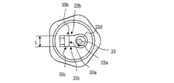
- FIG. 2 is a front view of the sample collection device viewed from the tip.
- FIG. 3 is an enlarged side view showing a distal end portion of the sample collection device.
- FIG. 4 is an enlarged side view showing the tip of the sample collection device.
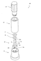
- FIG. 5 is an exploded perspective view of the sample preparation device.
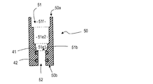
- FIG. 6 is a sectional view parallel to the longitudinal direction of the reagent container of the sample preparation device.
- FIG. 7 is a sectional view parallel to the longitudinal direction of the stopper of the sample preparation device.
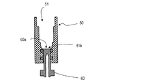
- FIG. 8 is a cross-sectional view illustrating a state where the stopper is inserted into the reagent container.
- FIG. 10A is a schematic diagram showing a procedure for collecting blood as a liquid sample and performing a process before measuring HbA1c in blood using the sample preparation device.
- FIG. 10B is a schematic diagram showing a procedure for collecting blood as a liquid sample and performing a process before measuring HbA1c in blood using the sample preparation device.
- FIG. 10C is a schematic diagram showing a procedure for collecting blood as a liquid sample and performing a process before measuring HbA1c in blood using the sample preparation device.
- FIG. 10D is a schematic diagram showing a procedure for collecting blood as a liquid sample and performing a process before measuring HbA1c in blood using the sample preparation device.
- FIG. 11A is a cross-sectional view of the sample preparation device during use.
- FIG. 11B is a cross-sectional view of the sample preparation device during use.
- FIG. 11C is a cross-sectional view of the sample preparation device in use.
- FIG. 12 is a perspective view showing another embodiment of the sample collection device.
- FIG. 13 is a side view of the sample collection device shown in FIG.
- FIG. 14 is an enlarged side view showing a distal end portion of the sample collection device shown in FIG.
- FIG. 15 is a front view of the sample collection device shown in FIG.
- FIG. 16 is a perspective view showing another embodiment of the sample collection device.
- FIG. 17 is a side view of the sample collection device shown in FIG.
- FIG. 18 is an enlarged side view showing the distal end portion of the sample collection device shown in FIG.
- FIG. 19 is a front view of the sample collection device shown in FIG.
- a capillary tube As a method of collecting a small and fixed amount of a sample, a capillary tube is sometimes used.
- a capillary By using a capillary, liquid can be collected without using a driving mechanism such as a pump.
- a sample collected by a capillary tube is generally held by capillary force, it is necessary to apply a force larger than the capillary force to the liquid in order to transfer the collected liquid, and the collected liquid sample Release may not be easy.
- the inventor of the present application has conceived a sampling device having a novel structure.
- the outline of the sample collection device and the sample preparation device of the present disclosure is as follows.
- a gripper A sampling unit connected to the gripping unit, The sampling unit includes a first surface, a second surface and a third surface adjacent to the first surface with the first surface interposed therebetween, and an opening in the first surface, the second surface, and the third surface.
- the sampling unit has a first surface, a second surface and a third surface respectively adjacent to the first surface with the first surface interposed therebetween, 3.
- the sampling device wherein the openings at both ends of the capillary are located on the second surface and the third surface, and the openings on the side surfaces of the capillary are located on the first surface.
- the sampling unit has a second surface and a third surface adjacent to the first surface with the first surface interposed therebetween, Item 5.
- the sampling device according to Item 4, wherein the groove shape has openings in the second surface and the third surface, and has the groove-shaped opening in the first surface.
- the sampling device according to any one of items 1 to 9, wherein the grip portion extends in a longitudinal direction, and has a polygonal shape in a cross section perpendicular to the longitudinal direction.
- the sampling device of item 10 wherein the polygonal shape is a pentagon.
- Item 12 Item 12.
- the grip extends in the longitudinal direction, The sampling device according to any one of items 1, 3 and 5, wherein the capillary has a longitudinal direction in a direction perpendicular to a longitudinal direction of the grip.
- the sampling device according to item 13 wherein the first surface is perpendicular to a longitudinal direction of the grip.
- the collection unit includes: A concave portion located on the first surface; A reagent arranged in the recess, Item 15.
- the collection unit includes: A fourth surface perpendicular to the longitudinal direction of the grip portion and adjacent to the first surface; A concave portion located on the fourth surface; A reagent arranged in the recess, Item 17.
- sampling device further comprising: [Item 18] A sampling device according to any one of items 1 to 17, A reagent having an opening and a bottom, and having a chamber capable of housing the collection unit by inserting a part of the sample collection device from the opening, and a through-hole connecting the bottom and the outside.
- a container A stopper that is insertable into the through hole and has a first end face and a second end face located in a longitudinal direction, and a side face located between the first end face and the second end face; A first discharge hole having an opening on an end face and extending along a longitudinal direction, and a stopper having an opening on the side surface and having a second discharge hole connected to the first discharge hole,
- the sample preparation device wherein the stopper is movable between a holding position where the first surface is located at the bottom of the chamber and a discharge position where an opening of the side surface is exposed in the chamber.
- a sample collection device and a sample preparation device for collecting blood as a liquid sample and measuring the amount of hemoglobin A1c (hereinafter, referred to as HbA1c) bound to sugar in the blood will be described as examples.
- HbA1c hemoglobin A1c
- An embodiment of the present disclosure will be described.
- the sample collection device and the sample preparation device of the present disclosure can be used not only for collecting blood but also for collecting other liquid samples.
- HbA1c-derived fructosyl valyl histidine is generated by dissolving the cell membrane of erythrocytes from the collected blood and decomposing hemoglobin. By quantifying this fructosyl valyl histidine, the amount of HbA1c in the blood is estimated.
- a sampling device for measuring HbA1c is generally used integrally with a sample preparation device.
- a sample collection device will be described first, and then a sample preparation device will be described.
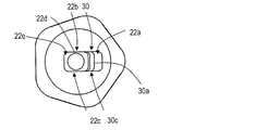
- FIG. 1 is a perspective view showing a sample collection device 101 of the present embodiment
- FIG. 2 is a front view as viewed from the tip.
- the sample collection device 101 includes the holding unit 10 and the collection unit 20.
- the sampling device 101 is a device for collecting a very small amount of liquid, and the amount of the collected liquid is, for example, several tens of microliters or less, and typically 1 to 10 ⁇ l or less. For this reason, the sampling device 101 has a size that can be gripped by fingers.
- the gripper 10 is an area for gripping the sample collection device 101, and has a shape and a size that are easy to be pinched (easily pinched) with a fingertip, for example.
- the grip portion 10 has, for example, a column shape having a length of about 1 to 5 cm in the longitudinal direction A and a width of a cross section perpendicular to the longitudinal direction of about 1 to 2 cm.
- the cross section perpendicular to the longitudinal direction may be circular, elliptical, or the like, or may be polygonal. In the case of having a polygonal shape, when the finger is pinched, for example, the surface in contact with the fingertip is flat, so that it is easy to stably hold the sample collection device 101.
- the gripper 10 has a pentagonal shape in a cross section perpendicular to the longitudinal direction, it is possible to secure a sufficient size of a plane with which a fingertip contacts and to arrange many side surfaces. For this reason, for example, when the grip part 10 is sandwiched between the thumb, the index finger and the middle finger, or when the grip part is sandwiched between the thumb and the index finger and the side part of the middle finger is attached to the grip part 10, these fingers can be brought into contact with each other. Multiple sides can be selected. Therefore, the sample collection device 101 can be stably supported regardless of the direction in which the grip portion 10 is pinched.
- the cross section of the grip part 10 is polygonal, the vicinity of the vertex of each side is configured to be round, and the boundary of each side may not be clear.
- the grip 10 When the cross section of the grip 10 is polygonal, the grip 10 includes a plurality of side surfaces corresponding to the polygon. Of the plurality of surfaces, for example, a specific surface may be colored, or a design serving as a marker may be formed on the specific surface by color or unevenness. Thereby, the user can recognize a specific surface, and when supporting the grip portion 10, it becomes easy to recognize the direction and the position of the capillary tube 30 provided at the distal end portion described later.
- the sampling unit 20 is connected to one end of the grip unit 10 in the longitudinal direction A, and includes a base 21 and a tip 22.
- a capillary (capillary space) 30 for collecting a liquid is provided at the distal end portion 22.
- the base 21 separates the distal end portion 22 from the grip portion 10 in order to prevent the distal end portion 22 from being difficult to see with the finger when the grip portion 10 is supported by the finger.
- the base 21 has, for example, a cylindrical shape.
- a groove 21g is provided along the circumferential direction of the side surface of the base 21, and the O-ring 40 is disposed in the groove 21g.
- the base 21 may not be provided depending on the shape of the grip 10. For example, in a case where the side of the grip 10 connected to the sampling unit 20 is elongated and configured so as not to support a finger, the tip 22 may be directly connected to the grip 10.
- FIG. 3 and FIG. 4 are side views showing the enlarged front end portion.
- the tip 22 has the capillary tube 30 as described above.
- the capillary tube 30 is disposed at the distal end portion 22 so as to have openings 30b and 30c located at both ends and an opening 30a located at a side surface.
- the capillary tube 30 has a groove shape, and the distal end portion 22 has a first surface 22a, and the capillary tube 30 is positioned in the first surface 22a such that the opening 30a that is the opening of the groove is located. It is provided on one surface 22a.
- the first surface 22a is perpendicular to the longitudinal direction of the grip 10.
- perpendicular means that the angle is 80 to 100 °.
- the distal end portion 22 has a second surface 22b and a third surface 22c adjacent to the first surface 22a and sandwiching the first surface 22a, and the second surface 22b and the third surface 22c. Are provided with an opening 30b and an opening 30c of the capillary tube 30.
- the opening 30b is connected to the opening 30c by the opening 30a, and the opening 30b and the opening 30c communicate with each other.
- the capillaries 30 are provided with openings 30c in all of the portions that are in contact with the first surface 22a.
- the capillary 30 may be closed on at least a part of the first surface 22a.
- the capillary tube 30 has a longitudinal direction in a direction perpendicular to the longitudinal direction A of the grip portion 10 and extends in the longitudinal direction.
- the capillary 30 preferably has a U-shape in a cross section perpendicular to the longitudinal direction. By having a U-shape, it is possible to adjust the direction and size of the action of the capillary force between the linear portion and the curved portion in the cross section, and the release of the held liquid sample.
- the bottom of the U-shape that is, the inner surface of the first surface 22a on the side remote from the opening 30a is a curved surface, when the liquid sample is drawn in by the capillary force, bubbles are less likely to bite. For this reason, it is possible to more accurately measure the predetermined amount of the liquid sample.
- the openings 30b and 30c preferably have the same shape as the cross section. It is preferable that the width W of the openings 30b and 30c parallel to the first surface 22a is substantially equal to the depth D perpendicular to the first surface 22a. Specifically, it is preferable that the width W and the depth D satisfy the relationship of 0.9 ⁇ W / D ⁇ 1.1.
- the capillary 30 has such a size that an appropriate capillary force according to a liquid to be collected works.
- the width W and the depth D are preferably, for example, values in a range of 800 ⁇ m to 1 mm.
- the length L of the capillary tube 30 in the longitudinal direction is preferably in a range of 2 mm to 4 mm. The amount of the liquid sample to be collected can be adjusted mainly by the length L in the longitudinal direction.
- the inner wall of the capillary tube 30 may have at least one of a linear n concave portion and a convex portion extending parallel to the longitudinal direction.
- the concave portions or the convex portions By having the concave portions or the convex portions, the liquid sample can easily flow through the openings 30b and 30c, or the surface area of the inner wall can be increased by the unevenness, so that the holding force due to the capillary force can be increased, and the liquid sample can be held. And the properties of the release can be adjusted.
- a linear unevenness may be, for example, a resin molding flow line generated when the resin flows in the mold when the sample collection device 101 is manufactured by injection molding using a mold. .
- a reagent used for the pretreatment is arranged at the tip portion 22.
- a concave portion 22d may be provided on the first surface 22a, and the reagent 23 may be disposed in the concave portion 22d.
- the sample collection device 101 may further include a protease that is a hemoglobin degrading enzyme as the reagent 23.
- the recess 22d may be arranged near the opening 30a of the capillary tube 30.
- the capillary tube 30 has openings in three directions. Therefore, when a liquid sample is collected, it is possible to suck the liquid sample from the three openings, and when the liquid sample flows into the capillary 30, the air filling the capillary 30 is opened in three directions. Can be exhausted. For example, when blood is sucked from the opening 30a located on the first surface 22a, the air filling the capillary 30 is discharged from the openings 30b and 30c at both ends. For this reason, blood is swiftly permeated into the capillary 30 without biting air bubbles into the capillary 30. Therefore, it is easy to accurately measure a fixed amount of the liquid sample.
- the capillary 33 extends perpendicularly to the longitudinal direction A of the gripper 10, when the collected sample liquid is released into a liquid such as a pretreatment liquid, the amount of the pretreatment liquid is small. Even if the level of the pretreatment liquid is low, the entire capillary tube 30 can be immersed in the pretreatment liquid. Therefore, it is possible to release the collected liquid sample into a solution such as a small amount of pretreatment liquid, and it is possible to increase the concentration of the sample in the prepared solution when pretreatment is required.
- the reagent used for the pretreatment can be arranged close to the capillary 33, the reagent is dissolved in the pretreatment liquid, so that the sample released into the pretreatment liquid and the reagent are brought close to each other, and quickly. Can be reacted.
- FIG. 5 is an exploded perspective view of the sample preparation device 201.
- the sample preparation device 201 includes a sample collection device 101, a reagent container 50, a stopper 60, and a cover 70.
- the sampling device 101 has the structure described above.
- 6 and 7 are cross-sectional views of the reagent container 50 and the stopper 60 parallel to the longitudinal direction.
- the reagent container 50 has a columnar shape having an upper surface 50a and a lower surface 50b, and has a chamber 51 for accommodating at least the collection unit 20 of the sample collection device 101 and a through hole 52 therein.
- the chamber 51 has an opening 51o on the upper surface 50a, and the sampling device 101 is inserted into the chamber 51 from the opening 51c.
- the chamber 51 has a bottom 51b.
- the chamber 51 includes a first portion 51e1 in which the distal end portion 22 of the sampling unit 20 of the sample collection device 101 is inserted, a second portion 51e2 in which the base 21 is inserted, and a part of the gripper 10. And a third portion 51f to be inserted.
- the through hole 52 is provided in the bottom surface 50b and connects the bottom 51b of the chamber 51 to the outside.
- a groove is provided on the side surface of the through hole 52 along the circumferential direction, and O-rings 41 and 42 are arranged in the groove.
- the stopper 60 has a columnar shape having a first end face 60a and a second end face 60b, and a side face 60c located between the first end face 60a and the second end face 60b, and can be inserted into the through hole 52 of the reagent container 50. is there.
- first discharge hole 61 extending along the longitudinal direction of the column shape is provided in the second end face 60b.
- second discharge hole 62 having an opening on the side surface 60 c and extending perpendicularly to the longitudinal direction and connected to the first discharge hole 61 is provided.
- a convex portion 63 is provided on a side surface 60c near the second end surface 60b.
- the stopper 60 is used in a state of being inserted into the reagent container 50.
- FIG. 8 and FIG. 9 show cross sections in a state where the stopper 60 is inserted into the through hole 52 of the reagent container 50.
- the stopper 60 has a holding position where the first end face 60 a is located at the bottom 51 b of the chamber 51, the stopper 60 is further inserted into the through hole 52, and the first end face 60 a rises from the bottom 51 b,
- the opening of the second discharge hole 62 provided in the side surface 60c is movable between a discharge position located in the chamber 51.
- the stopper 60 may be configured to be rotated around the longitudinal axis and move in the longitudinal direction only when the stopper 60 is positioned at a specific angular position. .
- the reagent solution for dissolving the sample is held in the chamber 51 with the stopper 60 at the holding position.
- the stopper 60 is at the discharge position, the reagent solution in the chamber 51 is discharged from the second discharge hole 62 to the outside through the first discharge hole 61.
- the gap between the through hole 52 and the stopper 60 is sealed because the O-rings 41 and 42 are arranged in the through hole 52, and the chamber 60 is closed.
- the liquid held in 51 is suppressed from leaking from through-hole 52.
- the cover 70 has a space 70 e, stores the stopper 60 inserted in the reagent container 50, and supports the reagent container 50.
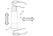
- FIGS. 10A to 10D are schematic diagrams showing a procedure for collecting blood as a liquid sample and performing pretreatment before measuring HbA1c in blood using the sample preparation device 201.
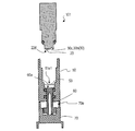
- FIGS. 2 shows a cross section of a sample preparation device 201 in the inside.
- a protease 23 which is a hemoglobin-degrading enzyme is disposed as a reagent 23 in the concave portion 22d of the sample collection device 101.
- the stopper 60 is inserted into the through hole 52 of the reagent container 50 so as to be located at the holding position.
- the reagent container 50 is supported by the cover 70 so that the stopper 60 is housed in the space 70e.
- the chamber 51 of the reagent container 50 holds a lysis solution 53 containing a surfactant as a hemolytic agent for lysing red blood cells in blood.
- FIG. 10A a needle is pierced into a fingertip to cause a minute amount of bleeding, and blood is brought into contact with any one of the openings 30a, 30b, and 30c of the distal end portion 22 of the sampling device 101, whereby the capillary 30 Let the blood be sucked.
- FIG. 10B the collection unit 20 of the sample collection device 101 is inserted into the opening of the chamber 51 of the reagent container 50, and the cover 70 and the sample collection device 101 are sandwiched between fingers as shown in FIG. 10C. , In the vertical direction (longitudinal direction) and in the horizontal direction.
- the cover 70 is removed, and the second end face 60b of the stopper 60 is pressed against the sample introduction part 300 of the measuring device.
- the stopper 60 is inserted into the through hole 52 of the reagent container 50 by pressing the second end face 60 b of the stopper 60 against the sample introduction part 300, and the first end face 60 a of the sample collection device 101 is The sample collecting device 101 comes into contact with the first surface 22a of the distal end portion 22 and is pushed up.
- the projection 63 of the stopper 60 contacts the bottom surface 50 b of the reagent container 50, the opening of the second discharge hole 62 of the stopper 60 is exposed in the chamber 51.
- the solution 53 is introduced into the sample introduction part 300 of the measuring device through the second discharge hole 62 and the first discharge hole 61.
- the measuring device guides the lysis solution 53 introduced from the sample introduction part 300 to the sensor, and measures the concentration of HbA1c and the concentration of total hemoglobin by an electrochemical reaction.
- sampling device (Other forms of sampling device) Various modifications to the sampling device are possible.
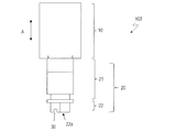
- FIG. 12 is a perspective view of another form of the sampling device 102
- FIG. 13 is a side view of the sampling device 102
- FIG. 14 is an enlarged side view showing the distal end portion of the sample collection device 102
- FIG. 15 is a front view of the sample collection device 102.
- the sample collection device 102 is different from the sample collection device 101 in that the first surface on which the capillary tube 30 is provided is not perpendicular to the longitudinal direction A of the gripper 10.
- the collecting section 20 includes a fourth surface 22e adjacent to the first surface 22a, and a concave portion 22d for holding a reagent is provided on the fourth surface 22e.
- the fourth surface 22 e is, for example, perpendicular to the longitudinal direction A of the grip 10. It is preferable that the capillary tube 30 is close to the boundary between the first surface 22a and the fourth surface 22e.
- the distal end portion 22 has a shape in which the distal end side is thin in a side view. For this reason, when the user collects the blood of the fingertip, for example, the portion where the capillary tube 30 is located is easily recognized, and the portion where the capillary tube 30 is located is more accurately brought into contact with the blood of the fingertip. Therefore, the operability and convenience of the operator at the time of blood collection can be improved.
- FIG. 16 is a perspective view of a sample collection device 103 of another embodiment
- FIG. 17 is a side view of the sample collection device 103
- FIG. 18 is a side view showing, on an enlarged scale, the distal end portion of the sample collection device 103
- FIG. 19 is a front view of the sample collection device 103.
- the sample collection device 103 is different from the sample collection device 101 in that the sample collection device 103 includes the grip 10 having a different shape.
- the gripper 10 of the sample collection device 103 has a substantially rectangular shape in a cross section perpendicular to the longitudinal direction.
- the grip part 10 includes a pair of first side surfaces 10a and 10b and a pair of second side surfaces 10c and 10d, and the area of the first side surfaces 10a and 10b is larger than the area of the second side surfaces 10c and 10d.
- the first side surface 10a and the first side surface 10b are located on opposite sides, and similarly, the second side surface 10c and the second side surface 10c are located on opposite sides.
- the first side surfaces 10a and 10b are substantially perpendicular to the longitudinal direction of the capillary 30.
- the sample collection device 103 When the sample collection device 103 is used, since the first side surfaces 10a and 10b are large, in particular, even without any instruction, the user holds the first side surfaces 10a and 10b on the first side surfaces 10a and 10b so as to pinch the first side surfaces 10a and 10b. For example, a thumb and an index finger are arranged. In this state, when the user moves the wrist to swing the sampling device 103, the sampling device 103 is swung substantially along the longitudinal direction of the capillary tube 30. When swinging in this direction, the liquid sample collected from the openings 30b and 30c is likely to be released due to the inertial force.
- the user can swing the sample collection device 103 in a direction in which the collected liquid sample is easily released without any special instructions. Therefore, the pretreatment of the sample can be completed by a short swinging operation, and the operability is excellent.
- the sample collection device and the sample preparation device of the present disclosure can collect various liquid samples such as blood, and can adjust the liquid sample after collection, and can be suitably used for blood component analysis and the like.
Landscapes
- Health & Medical Sciences (AREA)
- Life Sciences & Earth Sciences (AREA)
- Hematology (AREA)
- Engineering & Computer Science (AREA)
- General Health & Medical Sciences (AREA)
- Biomedical Technology (AREA)
- Molecular Biology (AREA)
- Pathology (AREA)
- Physics & Mathematics (AREA)
- Chemical & Material Sciences (AREA)
- Surgery (AREA)
- Heart & Thoracic Surgery (AREA)
- Animal Behavior & Ethology (AREA)
- Biophysics (AREA)
- Public Health (AREA)
- Veterinary Medicine (AREA)
- Medical Informatics (AREA)
- Immunology (AREA)
- Analytical Chemistry (AREA)
- Urology & Nephrology (AREA)
- General Physics & Mathematics (AREA)
- Biochemistry (AREA)
- Microbiology (AREA)
- Cell Biology (AREA)
- Biotechnology (AREA)
- Food Science & Technology (AREA)
- Medicinal Chemistry (AREA)
- Chemical Kinetics & Catalysis (AREA)
- Clinical Laboratory Science (AREA)
- Dermatology (AREA)
- Hydrology & Water Resources (AREA)
- Sampling And Sample Adjustment (AREA)
- Investigating Or Analysing Biological Materials (AREA)
Abstract
L'invention concerne un dispositif de prélèvement d'échantillon qui comprend une partie de préhension 10 et une partie de prélèvement 20 reliée à la partie de préhension 10. La partie de collecte 20 comprend une première surface 22a et un capillaire en forme de rainure 30 qui est formé sur la première surface 22a et a des ouvertures formées sur ses deux extrémités.
Priority Applications (2)
| Application Number | Priority Date | Filing Date | Title |
|---|---|---|---|
| JP2020527660A JP7383611B2 (ja) | 2018-06-29 | 2019-06-27 | 試料採取デバイスおよび試料調製装置 |
| US17/256,496 US20210276007A1 (en) | 2018-06-29 | 2019-06-27 | Sample collection device and sample preparation device |
Applications Claiming Priority (2)
| Application Number | Priority Date | Filing Date | Title |
|---|---|---|---|
| JP2018-124219 | 2018-06-29 | ||
| JP2018124219 | 2018-06-29 |
Publications (1)
| Publication Number | Publication Date |
|---|---|
| WO2020004590A1 true WO2020004590A1 (fr) | 2020-01-02 |
Family
ID=68984902
Family Applications (1)
| Application Number | Title | Priority Date | Filing Date |
|---|---|---|---|
| PCT/JP2019/025720 Ceased WO2020004590A1 (fr) | 2018-06-29 | 2019-06-27 | Dispositif de prélèvement d'échantillon et dispositif de préparation d'échantillon |
Country Status (3)
| Country | Link |
|---|---|
| US (1) | US20210276007A1 (fr) |
| JP (1) | JP7383611B2 (fr) |
| WO (1) | WO2020004590A1 (fr) |
Cited By (1)
| Publication number | Priority date | Publication date | Assignee | Title |
|---|---|---|---|---|
| US11399811B2 (en) * | 2020-06-30 | 2022-08-02 | Texas Tech University System | Method and apparatus for collection of fluid samples |
Citations (2)
| Publication number | Priority date | Publication date | Assignee | Title |
|---|---|---|---|---|
| JPH09203696A (ja) * | 1996-01-25 | 1997-08-05 | Daikin Ind Ltd | 点着補助具 |
| WO2017122372A1 (fr) * | 2016-01-14 | 2017-07-20 | 株式会社島津製作所 | Dispositif de prélèvement d'échantillon, support de dispositif de prélèvement d'échantillon et procédé de prétraitement d'échantillon qui utilise le dispositif de prélèvement d'échantillon |
Family Cites Families (4)
| Publication number | Priority date | Publication date | Assignee | Title |
|---|---|---|---|---|
| US5627041A (en) * | 1994-09-02 | 1997-05-06 | Biometric Imaging, Inc. | Disposable cartridge for an assay of a biological sample |
| US20100024530A1 (en) * | 2008-07-29 | 2010-02-04 | Hopkins Ii Robert E | Lateral Flow Devices |
| US20120271125A1 (en) * | 2011-04-11 | 2012-10-25 | Seventh Sense Biosystems, Inc. | Devices and methods for delivery and/or withdrawal of fluids and preservation of withdrawn fluids |
| US10531657B2 (en) * | 2015-12-07 | 2020-01-14 | Coopersurgical, Inc. | Low temperature specimen carriers and related methods |
-
2019
- 2019-06-27 JP JP2020527660A patent/JP7383611B2/ja active Active
- 2019-06-27 WO PCT/JP2019/025720 patent/WO2020004590A1/fr not_active Ceased
- 2019-06-27 US US17/256,496 patent/US20210276007A1/en not_active Abandoned
Patent Citations (2)
| Publication number | Priority date | Publication date | Assignee | Title |
|---|---|---|---|---|
| JPH09203696A (ja) * | 1996-01-25 | 1997-08-05 | Daikin Ind Ltd | 点着補助具 |
| WO2017122372A1 (fr) * | 2016-01-14 | 2017-07-20 | 株式会社島津製作所 | Dispositif de prélèvement d'échantillon, support de dispositif de prélèvement d'échantillon et procédé de prétraitement d'échantillon qui utilise le dispositif de prélèvement d'échantillon |
Cited By (1)
| Publication number | Priority date | Publication date | Assignee | Title |
|---|---|---|---|---|
| US11399811B2 (en) * | 2020-06-30 | 2022-08-02 | Texas Tech University System | Method and apparatus for collection of fluid samples |
Also Published As
| Publication number | Publication date |
|---|---|
| US20210276007A1 (en) | 2021-09-09 |
| JP7383611B2 (ja) | 2023-11-20 |
| JPWO2020004590A1 (ja) | 2021-08-02 |
Similar Documents
| Publication | Publication Date | Title |
|---|---|---|
| JP7621580B2 (ja) | 液体試料採取装置 | |
| CN1902484B (zh) | 一次性流体试样采集装置 | |
| JP6374389B2 (ja) | テスト装置並びにテスト方法及びそのプログラム | |
| JP3869810B2 (ja) | マイクロ血球カウンタ | |
| KR101009447B1 (ko) | 체액 샘플링, 전처리 및 투입장치 및 방법 | |
| JPH10221221A (ja) | 液体採取装置 | |
| JP2011017717A (ja) | 血液検査装置 | |
| CN113495087B (zh) | Poct血细胞分析仪及其检测方法 | |
| CN101835423A (zh) | 取样和分配装置 | |
| GB2445527A (en) | Improvements in liquid photometry | |
| JP2020034427A (ja) | 血液採取器具 | |
| EP1921439A1 (fr) | Dispositif, instrument et procede de mesure | |
| US20150273466A1 (en) | Sample analyzer and reagent container | |
| US5968329A (en) | Interchangeable multiple test system for portable analyzer | |
| KR20160051253A (ko) | 체외진단용 분석장치의 카트리지 | |
| JP2014178315A (ja) | ピペット針の保持装置 | |
| KR20140068437A (ko) | 스포이드 | |
| WO2020004590A1 (fr) | Dispositif de prélèvement d'échantillon et dispositif de préparation d'échantillon | |
| JPH0867B2 (ja) | 接種器及び組立体 | |
| JP4811267B2 (ja) | マイクロチップ及びそれを用いた分析デバイス | |
| WO2005039407A2 (fr) | Systeme et procede de prelevement sur le cordon ombilical | |
| WO2009084451A1 (fr) | Dispositif à buse et analyseur d'échantillons liquides | |
| KR101684689B1 (ko) | 혈액 채취 장치 | |
| CN113495086B (zh) | Poct血细胞分析仪及试剂盒 | |
| EP3438654A2 (fr) | Puce d'analyse |
Legal Events
| Date | Code | Title | Description |
|---|---|---|---|
| 121 | Ep: the epo has been informed by wipo that ep was designated in this application |
Ref document number: 19824721 Country of ref document: EP Kind code of ref document: A1 |
|
| ENP | Entry into the national phase |
Ref document number: 2020527660 Country of ref document: JP Kind code of ref document: A |
|
| NENP | Non-entry into the national phase |
Ref country code: DE |
|
| 122 | Ep: pct application non-entry in european phase |
Ref document number: 19824721 Country of ref document: EP Kind code of ref document: A1 |