WO2020004590A1 - 試料採取デバイスおよび試料調製装置 - Google Patents
試料採取デバイスおよび試料調製装置 Download PDFInfo
- Publication number
- WO2020004590A1 WO2020004590A1 PCT/JP2019/025720 JP2019025720W WO2020004590A1 WO 2020004590 A1 WO2020004590 A1 WO 2020004590A1 JP 2019025720 W JP2019025720 W JP 2019025720W WO 2020004590 A1 WO2020004590 A1 WO 2020004590A1
- Authority
- WO
- WIPO (PCT)
- Prior art keywords
- longitudinal direction
- capillary
- sampling
- sample
- opening
- Prior art date
- Legal status (The legal status is an assumption and is not a legal conclusion. Google has not performed a legal analysis and makes no representation as to the accuracy of the status listed.)
- Ceased
Links
Images


Classifications
-
- B—PERFORMING OPERATIONS; TRANSPORTING
- B01—PHYSICAL OR CHEMICAL PROCESSES OR APPARATUS IN GENERAL
- B01L—CHEMICAL OR PHYSICAL LABORATORY APPARATUS FOR GENERAL USE
- B01L3/00—Containers or dishes for laboratory use, e.g. laboratory glassware; Droppers
- B01L3/50—Containers for the purpose of retaining a material to be analysed, e.g. test tubes
- B01L3/502—Containers for the purpose of retaining a material to be analysed, e.g. test tubes with fluid transport, e.g. in multi-compartment structures
- B01L3/5023—Containers for the purpose of retaining a material to be analysed, e.g. test tubes with fluid transport, e.g. in multi-compartment structures with a sample being transported to, and subsequently stored in an absorbent for analysis
-
- A—HUMAN NECESSITIES
- A61—MEDICAL OR VETERINARY SCIENCE; HYGIENE
- A61B—DIAGNOSIS; SURGERY; IDENTIFICATION
- A61B5/00—Measuring for diagnostic purposes; Identification of persons
- A61B5/15—Devices for taking samples of blood
- A61B5/150007—Details
- A61B5/150015—Source of blood
- A61B5/150022—Source of blood for capillary blood or interstitial fluid
-
- A—HUMAN NECESSITIES
- A61—MEDICAL OR VETERINARY SCIENCE; HYGIENE
- A61B—DIAGNOSIS; SURGERY; IDENTIFICATION
- A61B5/00—Measuring for diagnostic purposes; Identification of persons
- A61B5/15—Devices for taking samples of blood
- A61B5/150007—Details
- A61B5/150343—Collection vessels for collecting blood samples from the skin surface, e.g. test tubes, cuvettes
-
- A—HUMAN NECESSITIES
- A61—MEDICAL OR VETERINARY SCIENCE; HYGIENE
- A61B—DIAGNOSIS; SURGERY; IDENTIFICATION
- A61B5/00—Measuring for diagnostic purposes; Identification of persons
- A61B5/15—Devices for taking samples of blood
- A61B5/150007—Details
- A61B5/150755—Blood sample preparation for further analysis, e.g. by separating blood components or by mixing
-
- A—HUMAN NECESSITIES
- A61—MEDICAL OR VETERINARY SCIENCE; HYGIENE
- A61B—DIAGNOSIS; SURGERY; IDENTIFICATION
- A61B5/00—Measuring for diagnostic purposes; Identification of persons
- A61B5/15—Devices for taking samples of blood
- A61B5/151—Devices specially adapted for taking samples of capillary blood, e.g. by lancets, needles or blades
- A61B5/15101—Details
- A61B5/15103—Piercing procedure
- A61B5/15105—Purely manual piercing, i.e. the user pierces the skin without the assistance of any driving means or driving devices
-
- A—HUMAN NECESSITIES
- A61—MEDICAL OR VETERINARY SCIENCE; HYGIENE
- A61B—DIAGNOSIS; SURGERY; IDENTIFICATION
- A61B5/00—Measuring for diagnostic purposes; Identification of persons
- A61B5/15—Devices for taking samples of blood
- A61B5/151—Devices specially adapted for taking samples of capillary blood, e.g. by lancets, needles or blades
- A61B5/15142—Devices intended for single use, i.e. disposable
-
- A—HUMAN NECESSITIES
- A61—MEDICAL OR VETERINARY SCIENCE; HYGIENE
- A61B—DIAGNOSIS; SURGERY; IDENTIFICATION
- A61B5/00—Measuring for diagnostic purposes; Identification of persons
- A61B5/15—Devices for taking samples of blood
- A61B5/157—Devices characterised by integrated means for measuring characteristics of blood
-
- G—PHYSICS
- G01—MEASURING; TESTING
- G01N—INVESTIGATING OR ANALYSING MATERIALS BY DETERMINING THEIR CHEMICAL OR PHYSICAL PROPERTIES
- G01N1/00—Sampling; Preparing specimens for investigation
- G01N1/02—Devices for withdrawing samples
- G01N1/10—Devices for withdrawing samples in the liquid or fluent state
- G01N1/12—Dippers; Dredgers
-
- G—PHYSICS
- G01—MEASURING; TESTING
- G01N—INVESTIGATING OR ANALYSING MATERIALS BY DETERMINING THEIR CHEMICAL OR PHYSICAL PROPERTIES
- G01N33/00—Investigating or analysing materials by specific methods not covered by groups G01N1/00 - G01N31/00
- G01N33/48—Biological material, e.g. blood, urine; Haemocytometers
- G01N33/50—Chemical analysis of biological material, e.g. blood, urine; Testing involving biospecific ligand binding methods; Immunological testing
- G01N33/72—Chemical analysis of biological material, e.g. blood, urine; Testing involving biospecific ligand binding methods; Immunological testing involving blood pigments, e.g. haemoglobin, bilirubin or other porphyrins; involving occult blood
- G01N33/721—Haemoglobin
- G01N33/723—Glycosylated haemoglobin
-
- G—PHYSICS
- G01—MEASURING; TESTING
- G01N—INVESTIGATING OR ANALYSING MATERIALS BY DETERMINING THEIR CHEMICAL OR PHYSICAL PROPERTIES
- G01N33/00—Investigating or analysing materials by specific methods not covered by groups G01N1/00 - G01N31/00
- G01N33/48—Biological material, e.g. blood, urine; Haemocytometers
- G01N33/50—Chemical analysis of biological material, e.g. blood, urine; Testing involving biospecific ligand binding methods; Immunological testing
- G01N33/72—Chemical analysis of biological material, e.g. blood, urine; Testing involving biospecific ligand binding methods; Immunological testing involving blood pigments, e.g. haemoglobin, bilirubin or other porphyrins; involving occult blood
- G01N33/721—Haemoglobin
- G01N33/726—Devices
-
- B—PERFORMING OPERATIONS; TRANSPORTING
- B01—PHYSICAL OR CHEMICAL PROCESSES OR APPARATUS IN GENERAL
- B01L—CHEMICAL OR PHYSICAL LABORATORY APPARATUS FOR GENERAL USE
- B01L2200/00—Solutions for specific problems relating to chemical or physical laboratory apparatus
- B01L2200/16—Reagents, handling or storing thereof
-
- B—PERFORMING OPERATIONS; TRANSPORTING
- B01—PHYSICAL OR CHEMICAL PROCESSES OR APPARATUS IN GENERAL
- B01L—CHEMICAL OR PHYSICAL LABORATORY APPARATUS FOR GENERAL USE
- B01L2300/00—Additional constructional details
- B01L2300/04—Closures and closing means
- B01L2300/041—Connecting closures to device or container
-
- B—PERFORMING OPERATIONS; TRANSPORTING
- B01—PHYSICAL OR CHEMICAL PROCESSES OR APPARATUS IN GENERAL
- B01L—CHEMICAL OR PHYSICAL LABORATORY APPARATUS FOR GENERAL USE
- B01L2400/00—Moving or stopping fluids
- B01L2400/04—Moving fluids with specific forces or mechanical means
- B01L2400/0403—Moving fluids with specific forces or mechanical means specific forces
- B01L2400/0406—Moving fluids with specific forces or mechanical means specific forces capillary forces
Definitions
- This application relates to a sample collection device and a sample preparation device.
- Patent Literature 1 shows an example of such a sampling device.
- the sample collection device disclosed in Patent Literature 1 uses a capillary force to collect a liquid.
- the present disclosure provides a sampling device that facilitates release of a collected liquid sample.
- a sample collection device includes a holding unit and a collection unit connected to the holding unit, and the collection unit includes a first surface and a first surface sandwiching the first surface. It has adjacent second and third surfaces and a capillary tube having openings in the first, second and third surfaces.
- a sample fraud device that facilitates release of a collected liquid sample.
- FIG. 1 is a perspective view of one embodiment of a sample collection device.
- FIG. 2 is a front view of the sample collection device viewed from the tip.
- FIG. 3 is an enlarged side view showing a distal end portion of the sample collection device.
- FIG. 4 is an enlarged side view showing the tip of the sample collection device.
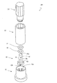
- FIG. 5 is an exploded perspective view of the sample preparation device.
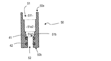
- FIG. 6 is a sectional view parallel to the longitudinal direction of the reagent container of the sample preparation device.
- FIG. 7 is a sectional view parallel to the longitudinal direction of the stopper of the sample preparation device.
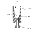
- FIG. 8 is a cross-sectional view illustrating a state where the stopper is inserted into the reagent container.
- FIG. 10A is a schematic diagram showing a procedure for collecting blood as a liquid sample and performing a process before measuring HbA1c in blood using the sample preparation device.
- FIG. 10B is a schematic diagram showing a procedure for collecting blood as a liquid sample and performing a process before measuring HbA1c in blood using the sample preparation device.
- FIG. 10C is a schematic diagram showing a procedure for collecting blood as a liquid sample and performing a process before measuring HbA1c in blood using the sample preparation device.
- FIG. 10D is a schematic diagram showing a procedure for collecting blood as a liquid sample and performing a process before measuring HbA1c in blood using the sample preparation device.
- FIG. 11A is a cross-sectional view of the sample preparation device during use.
- FIG. 11B is a cross-sectional view of the sample preparation device during use.
- FIG. 11C is a cross-sectional view of the sample preparation device in use.
- FIG. 12 is a perspective view showing another embodiment of the sample collection device.
- FIG. 13 is a side view of the sample collection device shown in FIG.
- FIG. 14 is an enlarged side view showing a distal end portion of the sample collection device shown in FIG.
- FIG. 15 is a front view of the sample collection device shown in FIG.
- FIG. 16 is a perspective view showing another embodiment of the sample collection device.
- FIG. 17 is a side view of the sample collection device shown in FIG.
- FIG. 18 is an enlarged side view showing the distal end portion of the sample collection device shown in FIG.
- FIG. 19 is a front view of the sample collection device shown in FIG.
- a capillary tube As a method of collecting a small and fixed amount of a sample, a capillary tube is sometimes used.
- a capillary By using a capillary, liquid can be collected without using a driving mechanism such as a pump.
- a sample collected by a capillary tube is generally held by capillary force, it is necessary to apply a force larger than the capillary force to the liquid in order to transfer the collected liquid, and the collected liquid sample Release may not be easy.
- the inventor of the present application has conceived a sampling device having a novel structure.
- the outline of the sample collection device and the sample preparation device of the present disclosure is as follows.
- a gripper A sampling unit connected to the gripping unit, The sampling unit includes a first surface, a second surface and a third surface adjacent to the first surface with the first surface interposed therebetween, and an opening in the first surface, the second surface, and the third surface.
- the sampling unit has a first surface, a second surface and a third surface respectively adjacent to the first surface with the first surface interposed therebetween, 3.
- the sampling device wherein the openings at both ends of the capillary are located on the second surface and the third surface, and the openings on the side surfaces of the capillary are located on the first surface.
- the sampling unit has a second surface and a third surface adjacent to the first surface with the first surface interposed therebetween, Item 5.
- the sampling device according to Item 4, wherein the groove shape has openings in the second surface and the third surface, and has the groove-shaped opening in the first surface.
- the sampling device according to any one of items 1 to 9, wherein the grip portion extends in a longitudinal direction, and has a polygonal shape in a cross section perpendicular to the longitudinal direction.
- the sampling device of item 10 wherein the polygonal shape is a pentagon.
- Item 12 Item 12.
- the grip extends in the longitudinal direction, The sampling device according to any one of items 1, 3 and 5, wherein the capillary has a longitudinal direction in a direction perpendicular to a longitudinal direction of the grip.
- the sampling device according to item 13 wherein the first surface is perpendicular to a longitudinal direction of the grip.
- the collection unit includes: A concave portion located on the first surface; A reagent arranged in the recess, Item 15.
- the collection unit includes: A fourth surface perpendicular to the longitudinal direction of the grip portion and adjacent to the first surface; A concave portion located on the fourth surface; A reagent arranged in the recess, Item 17.
- sampling device further comprising: [Item 18] A sampling device according to any one of items 1 to 17, A reagent having an opening and a bottom, and having a chamber capable of housing the collection unit by inserting a part of the sample collection device from the opening, and a through-hole connecting the bottom and the outside.
- a container A stopper that is insertable into the through hole and has a first end face and a second end face located in a longitudinal direction, and a side face located between the first end face and the second end face; A first discharge hole having an opening on an end face and extending along a longitudinal direction, and a stopper having an opening on the side surface and having a second discharge hole connected to the first discharge hole,
- the sample preparation device wherein the stopper is movable between a holding position where the first surface is located at the bottom of the chamber and a discharge position where an opening of the side surface is exposed in the chamber.
- a sample collection device and a sample preparation device for collecting blood as a liquid sample and measuring the amount of hemoglobin A1c (hereinafter, referred to as HbA1c) bound to sugar in the blood will be described as examples.
- HbA1c hemoglobin A1c
- An embodiment of the present disclosure will be described.
- the sample collection device and the sample preparation device of the present disclosure can be used not only for collecting blood but also for collecting other liquid samples.
- HbA1c-derived fructosyl valyl histidine is generated by dissolving the cell membrane of erythrocytes from the collected blood and decomposing hemoglobin. By quantifying this fructosyl valyl histidine, the amount of HbA1c in the blood is estimated.
- a sampling device for measuring HbA1c is generally used integrally with a sample preparation device.
- a sample collection device will be described first, and then a sample preparation device will be described.
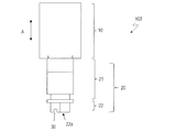
- FIG. 1 is a perspective view showing a sample collection device 101 of the present embodiment
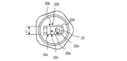
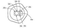
- FIG. 2 is a front view as viewed from the tip.
- the sample collection device 101 includes the holding unit 10 and the collection unit 20.
- the sampling device 101 is a device for collecting a very small amount of liquid, and the amount of the collected liquid is, for example, several tens of microliters or less, and typically 1 to 10 ⁇ l or less. For this reason, the sampling device 101 has a size that can be gripped by fingers.
- the gripper 10 is an area for gripping the sample collection device 101, and has a shape and a size that are easy to be pinched (easily pinched) with a fingertip, for example.
- the grip portion 10 has, for example, a column shape having a length of about 1 to 5 cm in the longitudinal direction A and a width of a cross section perpendicular to the longitudinal direction of about 1 to 2 cm.
- the cross section perpendicular to the longitudinal direction may be circular, elliptical, or the like, or may be polygonal. In the case of having a polygonal shape, when the finger is pinched, for example, the surface in contact with the fingertip is flat, so that it is easy to stably hold the sample collection device 101.
- the gripper 10 has a pentagonal shape in a cross section perpendicular to the longitudinal direction, it is possible to secure a sufficient size of a plane with which a fingertip contacts and to arrange many side surfaces. For this reason, for example, when the grip part 10 is sandwiched between the thumb, the index finger and the middle finger, or when the grip part is sandwiched between the thumb and the index finger and the side part of the middle finger is attached to the grip part 10, these fingers can be brought into contact with each other. Multiple sides can be selected. Therefore, the sample collection device 101 can be stably supported regardless of the direction in which the grip portion 10 is pinched.
- the cross section of the grip part 10 is polygonal, the vicinity of the vertex of each side is configured to be round, and the boundary of each side may not be clear.
- the grip 10 When the cross section of the grip 10 is polygonal, the grip 10 includes a plurality of side surfaces corresponding to the polygon. Of the plurality of surfaces, for example, a specific surface may be colored, or a design serving as a marker may be formed on the specific surface by color or unevenness. Thereby, the user can recognize a specific surface, and when supporting the grip portion 10, it becomes easy to recognize the direction and the position of the capillary tube 30 provided at the distal end portion described later.
- the sampling unit 20 is connected to one end of the grip unit 10 in the longitudinal direction A, and includes a base 21 and a tip 22.
- a capillary (capillary space) 30 for collecting a liquid is provided at the distal end portion 22.
- the base 21 separates the distal end portion 22 from the grip portion 10 in order to prevent the distal end portion 22 from being difficult to see with the finger when the grip portion 10 is supported by the finger.
- the base 21 has, for example, a cylindrical shape.
- a groove 21g is provided along the circumferential direction of the side surface of the base 21, and the O-ring 40 is disposed in the groove 21g.
- the base 21 may not be provided depending on the shape of the grip 10. For example, in a case where the side of the grip 10 connected to the sampling unit 20 is elongated and configured so as not to support a finger, the tip 22 may be directly connected to the grip 10.
- FIG. 3 and FIG. 4 are side views showing the enlarged front end portion.
- the tip 22 has the capillary tube 30 as described above.
- the capillary tube 30 is disposed at the distal end portion 22 so as to have openings 30b and 30c located at both ends and an opening 30a located at a side surface.
- the capillary tube 30 has a groove shape, and the distal end portion 22 has a first surface 22a, and the capillary tube 30 is positioned in the first surface 22a such that the opening 30a that is the opening of the groove is located. It is provided on one surface 22a.
- the first surface 22a is perpendicular to the longitudinal direction of the grip 10.
- perpendicular means that the angle is 80 to 100 °.
- the distal end portion 22 has a second surface 22b and a third surface 22c adjacent to the first surface 22a and sandwiching the first surface 22a, and the second surface 22b and the third surface 22c. Are provided with an opening 30b and an opening 30c of the capillary tube 30.
- the opening 30b is connected to the opening 30c by the opening 30a, and the opening 30b and the opening 30c communicate with each other.
- the capillaries 30 are provided with openings 30c in all of the portions that are in contact with the first surface 22a.
- the capillary 30 may be closed on at least a part of the first surface 22a.
- the capillary tube 30 has a longitudinal direction in a direction perpendicular to the longitudinal direction A of the grip portion 10 and extends in the longitudinal direction.
- the capillary 30 preferably has a U-shape in a cross section perpendicular to the longitudinal direction. By having a U-shape, it is possible to adjust the direction and size of the action of the capillary force between the linear portion and the curved portion in the cross section, and the release of the held liquid sample.
- the bottom of the U-shape that is, the inner surface of the first surface 22a on the side remote from the opening 30a is a curved surface, when the liquid sample is drawn in by the capillary force, bubbles are less likely to bite. For this reason, it is possible to more accurately measure the predetermined amount of the liquid sample.
- the openings 30b and 30c preferably have the same shape as the cross section. It is preferable that the width W of the openings 30b and 30c parallel to the first surface 22a is substantially equal to the depth D perpendicular to the first surface 22a. Specifically, it is preferable that the width W and the depth D satisfy the relationship of 0.9 ⁇ W / D ⁇ 1.1.
- the capillary 30 has such a size that an appropriate capillary force according to a liquid to be collected works.
- the width W and the depth D are preferably, for example, values in a range of 800 ⁇ m to 1 mm.
- the length L of the capillary tube 30 in the longitudinal direction is preferably in a range of 2 mm to 4 mm. The amount of the liquid sample to be collected can be adjusted mainly by the length L in the longitudinal direction.
- the inner wall of the capillary tube 30 may have at least one of a linear n concave portion and a convex portion extending parallel to the longitudinal direction.
- the concave portions or the convex portions By having the concave portions or the convex portions, the liquid sample can easily flow through the openings 30b and 30c, or the surface area of the inner wall can be increased by the unevenness, so that the holding force due to the capillary force can be increased, and the liquid sample can be held. And the properties of the release can be adjusted.
- a linear unevenness may be, for example, a resin molding flow line generated when the resin flows in the mold when the sample collection device 101 is manufactured by injection molding using a mold. .
- a reagent used for the pretreatment is arranged at the tip portion 22.
- a concave portion 22d may be provided on the first surface 22a, and the reagent 23 may be disposed in the concave portion 22d.
- the sample collection device 101 may further include a protease that is a hemoglobin degrading enzyme as the reagent 23.
- the recess 22d may be arranged near the opening 30a of the capillary tube 30.
- the capillary tube 30 has openings in three directions. Therefore, when a liquid sample is collected, it is possible to suck the liquid sample from the three openings, and when the liquid sample flows into the capillary 30, the air filling the capillary 30 is opened in three directions. Can be exhausted. For example, when blood is sucked from the opening 30a located on the first surface 22a, the air filling the capillary 30 is discharged from the openings 30b and 30c at both ends. For this reason, blood is swiftly permeated into the capillary 30 without biting air bubbles into the capillary 30. Therefore, it is easy to accurately measure a fixed amount of the liquid sample.
- the capillary 33 extends perpendicularly to the longitudinal direction A of the gripper 10, when the collected sample liquid is released into a liquid such as a pretreatment liquid, the amount of the pretreatment liquid is small. Even if the level of the pretreatment liquid is low, the entire capillary tube 30 can be immersed in the pretreatment liquid. Therefore, it is possible to release the collected liquid sample into a solution such as a small amount of pretreatment liquid, and it is possible to increase the concentration of the sample in the prepared solution when pretreatment is required.
- the reagent used for the pretreatment can be arranged close to the capillary 33, the reagent is dissolved in the pretreatment liquid, so that the sample released into the pretreatment liquid and the reagent are brought close to each other, and quickly. Can be reacted.
- FIG. 5 is an exploded perspective view of the sample preparation device 201.
- the sample preparation device 201 includes a sample collection device 101, a reagent container 50, a stopper 60, and a cover 70.
- the sampling device 101 has the structure described above.
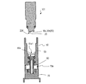
- 6 and 7 are cross-sectional views of the reagent container 50 and the stopper 60 parallel to the longitudinal direction.
- the reagent container 50 has a columnar shape having an upper surface 50a and a lower surface 50b, and has a chamber 51 for accommodating at least the collection unit 20 of the sample collection device 101 and a through hole 52 therein.
- the chamber 51 has an opening 51o on the upper surface 50a, and the sampling device 101 is inserted into the chamber 51 from the opening 51c.
- the chamber 51 has a bottom 51b.
- the chamber 51 includes a first portion 51e1 in which the distal end portion 22 of the sampling unit 20 of the sample collection device 101 is inserted, a second portion 51e2 in which the base 21 is inserted, and a part of the gripper 10. And a third portion 51f to be inserted.
- the through hole 52 is provided in the bottom surface 50b and connects the bottom 51b of the chamber 51 to the outside.
- a groove is provided on the side surface of the through hole 52 along the circumferential direction, and O-rings 41 and 42 are arranged in the groove.
- the stopper 60 has a columnar shape having a first end face 60a and a second end face 60b, and a side face 60c located between the first end face 60a and the second end face 60b, and can be inserted into the through hole 52 of the reagent container 50. is there.
- first discharge hole 61 extending along the longitudinal direction of the column shape is provided in the second end face 60b.
- second discharge hole 62 having an opening on the side surface 60 c and extending perpendicularly to the longitudinal direction and connected to the first discharge hole 61 is provided.
- a convex portion 63 is provided on a side surface 60c near the second end surface 60b.
- the stopper 60 is used in a state of being inserted into the reagent container 50.
- FIG. 8 and FIG. 9 show cross sections in a state where the stopper 60 is inserted into the through hole 52 of the reagent container 50.
- the stopper 60 has a holding position where the first end face 60 a is located at the bottom 51 b of the chamber 51, the stopper 60 is further inserted into the through hole 52, and the first end face 60 a rises from the bottom 51 b,
- the opening of the second discharge hole 62 provided in the side surface 60c is movable between a discharge position located in the chamber 51.
- the stopper 60 may be configured to be rotated around the longitudinal axis and move in the longitudinal direction only when the stopper 60 is positioned at a specific angular position. .
- the reagent solution for dissolving the sample is held in the chamber 51 with the stopper 60 at the holding position.
- the stopper 60 is at the discharge position, the reagent solution in the chamber 51 is discharged from the second discharge hole 62 to the outside through the first discharge hole 61.
- the gap between the through hole 52 and the stopper 60 is sealed because the O-rings 41 and 42 are arranged in the through hole 52, and the chamber 60 is closed.
- the liquid held in 51 is suppressed from leaking from through-hole 52.
- the cover 70 has a space 70 e, stores the stopper 60 inserted in the reagent container 50, and supports the reagent container 50.
- FIGS. 10A to 10D are schematic diagrams showing a procedure for collecting blood as a liquid sample and performing pretreatment before measuring HbA1c in blood using the sample preparation device 201.
- FIGS. 2 shows a cross section of a sample preparation device 201 in the inside.
- a protease 23 which is a hemoglobin-degrading enzyme is disposed as a reagent 23 in the concave portion 22d of the sample collection device 101.
- the stopper 60 is inserted into the through hole 52 of the reagent container 50 so as to be located at the holding position.
- the reagent container 50 is supported by the cover 70 so that the stopper 60 is housed in the space 70e.
- the chamber 51 of the reagent container 50 holds a lysis solution 53 containing a surfactant as a hemolytic agent for lysing red blood cells in blood.
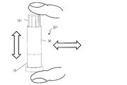
- FIG. 10A a needle is pierced into a fingertip to cause a minute amount of bleeding, and blood is brought into contact with any one of the openings 30a, 30b, and 30c of the distal end portion 22 of the sampling device 101, whereby the capillary 30 Let the blood be sucked.
- FIG. 10B the collection unit 20 of the sample collection device 101 is inserted into the opening of the chamber 51 of the reagent container 50, and the cover 70 and the sample collection device 101 are sandwiched between fingers as shown in FIG. 10C. , In the vertical direction (longitudinal direction) and in the horizontal direction.
- the cover 70 is removed, and the second end face 60b of the stopper 60 is pressed against the sample introduction part 300 of the measuring device.
- the stopper 60 is inserted into the through hole 52 of the reagent container 50 by pressing the second end face 60 b of the stopper 60 against the sample introduction part 300, and the first end face 60 a of the sample collection device 101 is The sample collecting device 101 comes into contact with the first surface 22a of the distal end portion 22 and is pushed up.
- the projection 63 of the stopper 60 contacts the bottom surface 50 b of the reagent container 50, the opening of the second discharge hole 62 of the stopper 60 is exposed in the chamber 51.
- the solution 53 is introduced into the sample introduction part 300 of the measuring device through the second discharge hole 62 and the first discharge hole 61.
- the measuring device guides the lysis solution 53 introduced from the sample introduction part 300 to the sensor, and measures the concentration of HbA1c and the concentration of total hemoglobin by an electrochemical reaction.
- sampling device (Other forms of sampling device) Various modifications to the sampling device are possible.
- FIG. 12 is a perspective view of another form of the sampling device 102
- FIG. 13 is a side view of the sampling device 102
- FIG. 14 is an enlarged side view showing the distal end portion of the sample collection device 102
- FIG. 15 is a front view of the sample collection device 102.
- the sample collection device 102 is different from the sample collection device 101 in that the first surface on which the capillary tube 30 is provided is not perpendicular to the longitudinal direction A of the gripper 10.
- the collecting section 20 includes a fourth surface 22e adjacent to the first surface 22a, and a concave portion 22d for holding a reagent is provided on the fourth surface 22e.
- the fourth surface 22 e is, for example, perpendicular to the longitudinal direction A of the grip 10. It is preferable that the capillary tube 30 is close to the boundary between the first surface 22a and the fourth surface 22e.
- the distal end portion 22 has a shape in which the distal end side is thin in a side view. For this reason, when the user collects the blood of the fingertip, for example, the portion where the capillary tube 30 is located is easily recognized, and the portion where the capillary tube 30 is located is more accurately brought into contact with the blood of the fingertip. Therefore, the operability and convenience of the operator at the time of blood collection can be improved.
- FIG. 16 is a perspective view of a sample collection device 103 of another embodiment
- FIG. 17 is a side view of the sample collection device 103
- FIG. 18 is a side view showing, on an enlarged scale, the distal end portion of the sample collection device 103
- FIG. 19 is a front view of the sample collection device 103.
- the sample collection device 103 is different from the sample collection device 101 in that the sample collection device 103 includes the grip 10 having a different shape.
- the gripper 10 of the sample collection device 103 has a substantially rectangular shape in a cross section perpendicular to the longitudinal direction.
- the grip part 10 includes a pair of first side surfaces 10a and 10b and a pair of second side surfaces 10c and 10d, and the area of the first side surfaces 10a and 10b is larger than the area of the second side surfaces 10c and 10d.
- the first side surface 10a and the first side surface 10b are located on opposite sides, and similarly, the second side surface 10c and the second side surface 10c are located on opposite sides.
- the first side surfaces 10a and 10b are substantially perpendicular to the longitudinal direction of the capillary 30.
- the sample collection device 103 When the sample collection device 103 is used, since the first side surfaces 10a and 10b are large, in particular, even without any instruction, the user holds the first side surfaces 10a and 10b on the first side surfaces 10a and 10b so as to pinch the first side surfaces 10a and 10b. For example, a thumb and an index finger are arranged. In this state, when the user moves the wrist to swing the sampling device 103, the sampling device 103 is swung substantially along the longitudinal direction of the capillary tube 30. When swinging in this direction, the liquid sample collected from the openings 30b and 30c is likely to be released due to the inertial force.
- the user can swing the sample collection device 103 in a direction in which the collected liquid sample is easily released without any special instructions. Therefore, the pretreatment of the sample can be completed by a short swinging operation, and the operability is excellent.
- the sample collection device and the sample preparation device of the present disclosure can collect various liquid samples such as blood, and can adjust the liquid sample after collection, and can be suitably used for blood component analysis and the like.
Landscapes
- Health & Medical Sciences (AREA)
- Life Sciences & Earth Sciences (AREA)
- Hematology (AREA)
- Engineering & Computer Science (AREA)
- General Health & Medical Sciences (AREA)
- Molecular Biology (AREA)
- Biomedical Technology (AREA)
- Pathology (AREA)
- Physics & Mathematics (AREA)
- Chemical & Material Sciences (AREA)
- Biophysics (AREA)
- Medical Informatics (AREA)
- Veterinary Medicine (AREA)
- Public Health (AREA)
- Animal Behavior & Ethology (AREA)
- Surgery (AREA)
- Heart & Thoracic Surgery (AREA)
- Immunology (AREA)
- Analytical Chemistry (AREA)
- Urology & Nephrology (AREA)
- General Physics & Mathematics (AREA)
- Biochemistry (AREA)
- Food Science & Technology (AREA)
- Medicinal Chemistry (AREA)
- Biotechnology (AREA)
- Cell Biology (AREA)
- Microbiology (AREA)
- Clinical Laboratory Science (AREA)
- Chemical Kinetics & Catalysis (AREA)
- Hydrology & Water Resources (AREA)
- Dermatology (AREA)
- Sampling And Sample Adjustment (AREA)
- Investigating Or Analysing Biological Materials (AREA)
Abstract
試料採取デバイスは、把持部10と、把持部10に接続された採取部20とを備え、採取部20は、第1面22aと、第1面22aに設けられ、両端に開口が形成された溝形状の毛細管30を有する。
Description
本願は、試料採取デバイスおよび試料調製装置に関する。
血液中の特性成分の分析などをおこなうため、微少量の液体を採取する試料採取デバイスが用いられる。特許文献1は、このような試料採取デバイスの一例を示している。特許文献1に開示された試料採取デバイスは、毛細管力を利用して液体を採取する。
従来の試料採取デバイスでは、保持した液体試料を放出することが困難な場合があった。本開示は、採取した液体試料の放出が容易である試料採取デバイスを提供する。
本開示ある態様による試料採取デバイスは、把持部と、前記把持部に接続された採取部とを備え、前記採取部は、第1面と、前記第1面を挟んで前記第1面にそれぞれ隣接した第2面および第3面と、前記第1面、前記第2面および前記第3面に開口を有する毛細管を有する。
本開示の一態様によれば、採取した液体試料の放出が容易である試料詐取デバイスが提供される。
微少かつ一定量の試料を採取する方法として毛細管が利用される場合がある。毛細管を利用することによって、ポンプなど駆動機構を用いることなく液体の採取が可能である。しかし、毛細管で採取した試料は、一般的に、毛細管力により保持されるため、採取した液体を移送させるために、毛細管力よりも大きな力を液体に働かせることが必要であり、採取した液体試料の放出が容易ではない場合がある。本願発明者はこのような課題に鑑み新規な構造を備えた試料採取デバイスを想到した。本開示の試料採取デバイスおよび試料調製装置の概要は以下の通りである。
[項目1]
把持部と、
前記把持部に接続された採取部と
を備え、
前記採取部は、第1面と、前記第1面を挟んで前記第1面にそれぞれ隣接した第2面および第3面と、前記第1面、前記第2面および前記第3面に開口を有する毛細管を有する、試料採取デバイス。
[項目2]
把持部と、
前記把持部に接続された採取部と
を備え、
前記採取部は、両端および前記両端の間の側面にそれぞれ位置する開口を有する毛細管を有する、試料採取デバイス。
[項目3]
前記採取部は、第1面と、前記第1面を挟んで前記第1面にそれぞれ隣接した第2面および第3面とを有し、
前記毛細管の前記両端の開口は、前記第2面および前記第3面に位置し、前記毛細管の側面の開口は、前記第1面に位置する、項目2に記載の試料採取デバイス。
[項目4]
把持部と、
前記把持部に接続された採取部と
を備え、
前記採取部は、第1面と、前記第1面に設けられ、両端に開口が形成された溝形状の毛細管を有する、試料採取デバイス。
[項目5]
前記採取部は、前記第1面を挟んで前記第1面にそれぞれ隣接した第2面および第3面を有し、
前記溝形状は、前記第2面および前記第3面に開口を有し、前記第1面に前記溝形状の開口を有する、項目4に記載の試料採取デバイス。
[項目6]
前記毛細管は、長手方向に垂直な断面においてU字形状を有する項目1から5のいずれか一項に記載の試料採取デバイス。
[項目7]
前記第2面および前記第3面に位置する開口は、前記第1面に位置する開口を介して連通している項目1、3および5のいずれか一項に記載の試料採取デバイス。
[項目8]
前記毛細管は、前記第1面の少なくとも一部において閉じている項目1、3および5のいずれか一項に記載の試料採取デバイス。
[項目9]
前記第2面および前記第3面における開口において、前記第1面と平行な幅Wと、前記第1面に垂直な深さDは0.9≦W/D≦1.1を満たしている、項目1、3および5のいずれか一項に記載の試料採取デバイス。
[項目10]
前記把持部は長手方向に伸びており、前記長手方向に垂直な断面において、多角形形状を有する項目1から9のいずれか一項に記載の試料採取デバイス。
[項目11]
前記多角形形状は五角形である項目10に記載の試料採取デバイス。
[項目12]
前記毛細管の内壁は、長手方向に平行な凹部または凸部を有する、項目1から11のいずれか一項に記載の試料採取デバイス。
[項目13]
前記把持部は長手方向に伸びており、
前記毛細管は、前記把持部の長手方向と垂直な方向に長手方向を有する項目1、3および5のいずれか一項に記載の試料採取デバイス。
[項目14]
前記第1面は、前記把持部の長手方向と垂直である、項目13に記載の試料採取デバイス。
[項目15]
前記採取部は、
前記第1面に位置する凹部と、
前記凹部に配置された試薬と、
をさらに有する項目14に記載の試料採取デバイス。
[項目16]
前記第1面は、前記把持部の長手方向と非垂直である、項目13に記載の試料採取デバイス。
[項目17]
前記採取部は、
前記把持部の長手方向と垂直であり、前記第1面と隣接する第4面と、
前記第4面に位置する凹部と、
前記凹部に配置された試薬と、
をさらに備える項目16に記載の試料採取デバイス。
[項目18]
項目1から17のいずれか一項に記載の試料採取デバイスと、
開口および底部を有し、前記開口から前記試料採取デバイスの一部を挿入することによって、前記採取部を収納することが可能なチャンバーと、前記底部と外部とを接続する貫通穴とを有する試薬容器と、
前記貫通穴に挿入可能であり、長手方向に位置する第1端面および第2端面と、前記第1端面および前記第2端面との間に位置する側面とを有するストッパーであって、前記第2端面に開口を有し、長手方向に沿って伸びる第1排出穴と、前記側面に開口を有し、前記第1排出穴に接続された第2排出穴とを有するストッパーと、を備え、
前記ストッパーは、前記第1面が前記チャンバーの底に位置する保持位置と、前記側面の開口が前記チャンバー内において露出する排出位置との間で移動可能である、試料調製装置。
以下、図面を参照しながら、本開示の試料採取デバイスおよび試料調製装置の実施形態を説明する。以下の説明では、液体試料として血液を採取し、血液中の糖と結合したヘモグロビンA1c(以下、HbA1cと記載する)の量を測定するための試料採取デバイスおよび試料調製装置を例に挙げて、本開示の実施形態を説明する。しかし、本開示の試料採取デバイスおよび試料調製装置は血液の採取に限らず、他の液体試料の採取に用いることが可能である。
血液中のHbA1cを測定する場合、例えば、手指の指先に針を刺し、微少量の出血を生じさせ、試料採取デバイスで血液を採取する。HbA1cは血液の赤血球中のヘモグロビンに含まれるため、採取した血液から赤血球の細胞膜を溶解し、ヘモグロビンを分解することによって、HbA1cに由来するフルクトシルバリルヒスチジンを生成させる。このフルクトシルバリルヒスチジンを定量することによって血液中のHbA1cの量を推定する。
上述したフルクトシルバリルヒスチジンを生成するまでの測定を行う前の前処理は、血液の採取後、速やかに行うことが好ましい。このため、HbA1cの測定のための試料採取デバイスは、試料調製装置と一体的に使用されることが一般的である。以下の実施形態では、まず試料採取デバイスを説明し、続いて試料調製装置を説明する。
(試料採取デバイス)
図1は本実施形態の試料採取デバイス101を示す斜視図であり、図2は、先端からみた正面図である。
図1は本実施形態の試料採取デバイス101を示す斜視図であり、図2は、先端からみた正面図である。
試料採取デバイス101は、把持部10および採取部20を備える。試料採取デバイス101は、微少量の液体を採取するデバイスであり、採取する液体の量は、例えば、数十マイクロリットル以下であり、典型的には、1~10μl以下である。このため、試料採取デバイス101は手指で把持し得る大きさを有する。
把持部10は、試料採取デバイス101を把持するための領域であり、例えば、指先でつまみ易い(挟み易い)形状および大きさを有する。具体的には、把持部10は、例えば、長手方向Aに1~5cm程度の長さを有し、長手方向に垂直な断面の幅が1~2cm程度である柱形状を有する。長手方向に垂直な断面は円形状、楕円形状等であってもよいし、多角形形状であってもよい。多角形形状を有する場合、指でつまんだ時に、例えば、指先と当接する面が平らであるため、安定して試料採取デバイス101を把持しやすい。例えば、把持部10が、長手方向に垂直な断面において五角形形状を有する場合、指先が接する平面の大きさを十分に確保し、かつ、多くの側面を配置できる。このため、例えば、親指、人差し指および中指で把持部10を挟んだ場合、あるいは、親指と人差し指で把持部を挟み、中指の側部を把持部10に添える場合に、これらの指に当接し得る側面を複数選択し得る。よって、どの向きから把持部10をつまんだ場合でも安定的に試料採取デバイス101を支持し得る。把持部10の断面が多角形形状である場合、各辺の頂点近傍が丸く構成され、各辺の境界が明瞭になっていなくてもよい。
また、把持部10の断面が多角形形状である場合、把持部10は多角形に対応した複数の側面を含む。この複数の面のうち、例えば、特定の面に色彩を施したり、特定の面にマーカーとなる意匠を色彩や凹凸によって形成してもよい。これにより、使用者が特定の面を認識すること可能となり、把持部10を支持した際に後述する先端部に設けた毛細管30の向きや位置を認識することが容易になる。
採取部20は把持部10の長手方向Aの一端に接続されており、基部21と先端部22とを含む。先端部22に液体を採取する毛細管(毛細管空間)30が設けられている。基部21は、把持部10を手指で支持した場合に、先端部22が手指で見づらくなるのを抑制するために、先端部22を把持部10から離間させる。基部21は例えば、円筒形形状を有している。本実施形態では、基部21の側面の円周方向に沿って溝21gが設けられており、溝21gにOリング40が配置されている。基部21は、把持部10の形状によっては設けられていなくてもよい。例えば、把持部10の採取部20と接続される側が細く伸びており、手指を支持しないように構成されている場合には、把持部10に先端部22が直接接続されていてもよい。
図3および図4は、先端部を拡大して示す側面図である。先端部22は、上述したように毛細管30を有する。毛細管30は両端に位置する開口30b、30cと、側面に位置する開口30aとを有するように先端部22に配置されている。具体的には、毛細管30は溝形状を有しており、先端部22は、第1面22aを有し、第1面22aに溝の開口である開口30aが位置するように毛細管30が第1面22aに設けられている。本実施形態では第1面22aは把持部10の長手方向に対して垂直である。ここで「垂直」とは、80~100°の角度をなしていることをいう。
より具体的には、先端部22は、第1面22aに隣接し、第1面22aを挟んで位置する第2面22bおよび第3面22cを有し、第2面22bおよび第3面22cに毛細管30の開口30bおよび開口30cが設けられている。
本実施形態では、開口30bは開口30aによって開口30cと接続されており、開口30bと開口30cとは連通している。言い換えれば、毛細管30は、第1面22aに接する部分の全てに開口30cが設けられている。しかし、毛細管30は、第1面22aの少なくとも一部において閉じていてもよい。これにより開口30aの大きさを異ならせ、毛細管30における毛細管力を調節することができ、毛細管30の液体試料の保持力を調節することが可能である。
毛細管30は、把持部10の長手方向Aに対して垂直な方向に長手方向を有し、長手方向に伸びている。毛細管30は、長手方向に垂直な断面においてU字形状を有していることが好ましい。U字形状を有することによって、断面における直線部分と曲線部とで毛細管力が作用する方向や大きさおよび保持した液体試料の放出を調整することが可能となる。また、U字形状の底、つまり、第1面22aの開口30aから遠い側の内面が曲面で構成されることによって、液体試料が毛細管力によって引き込まれる際、気泡が噛みにくくなる。このため、より正確に液体試料の所定量を測り取ることが可能である。
開口30bおよび開口30cは断面と同じ形状を有していることが好ましい。開口30b、30cの第1面22aと平行な幅Wと、第1面22aに垂直な深さDはほぼ等しいことが好ましい。具体的には、幅Wおよび深さDは、0.9≦W/D≦1.1の関係を満たしていることが好ましい。
毛細管30は、採取する液体に応じた適切な毛細管力が働くサイズを有することが好ましい。例えば、液体試料が血液である場合、幅Wおよび深さDは、例えば、800μm~1mmの範囲の値であることが好ましい。また、毛細管30の長手方向の長さLは、2mm~4mmの範囲の値であることが好ましい。採取する液体試料の量の調節は、主として長手方向の長さLで調整することが可能である。
毛細管30の内壁は、長手方向に平行に伸びる線状n凹部および凸部の少なくとも一方を有してよい。凹部または凸部を有することによって、開口30bおよび開口30cから液体試料が流入しやすくなったり、凹凸によって内壁の表面積が増大することによって毛細管力による保持力が高めることが可能となり、液体試料の保持や放出の特性を調節することが可能となる。このような線状の凹凸は、例えば、金型を用いた射出成形によって、試料採取デバイス101を作製する場合における、樹脂が金型内を流動する際に生じる樹脂成形流動線であってもよい。
試料採取デバイス101によって液体試料を採取した後、液体試料中の特定成分の測定のために、液体試料の前処理を行う必要がある場合には、前処理に用いる試薬を先端部22に配置してもよい。具体的には、第1面22aに凹部22dを設け、凹部22dに試薬23を配置してもよい。より具体的には、試料採取デバイス101は、ヘモグロビン分解酵素であるプロテアーゼを試薬23としてさらに備えていてもよい。凹部22dは毛細管30の開口30aに近接して配置してもよい。
試料採取デバイス101によれば、毛細管30は3方向に開口を有する。このため、液体試料を採取する際に、3つの開口から液体試料を吸引することが可能であり、また、液体試料が毛細管30に流入する際に毛細管30を満たしていた空気が3方向の開口のいずれかから排出され得る。例えば、第1面22aに位置する開口30aから血液が吸引される場合、両端である開口30bおよび開口30cから毛細管30を満たしていた空気が排出される。このため、毛細管30に速やかに、かつ、気泡が噛むことなく毛細管30全体に血液でみたされる。このため、液体試料を一定量、正確に測り取ることが容易である。
試料採取デバイス101から毛細管30を満たしている血液を放出(解放)する場合、3方が開口であることによって、開口から保持した液体試料を放出することが容易である。特に、第2面22bおよび第3面22cに、毛細管30の両端に位置する開口30bおよび開口30cを有しているので、例えば、把持部10を支持して、試料採取デバイス101を長手方向Aに揺動させた場合、毛細管30に支持された液体試料に慣性力が働き、開口30bおよび開口30cから放出されやすい。したがって、本実施形態の試料採取デバイス101によれば、採取した液体試料を容易にリリースすることが可能である。
また、毛細管33は把持部10の長手方向Aに対して垂直に伸びているため、採取した試料液体を前処理液等の液体中に放出する場合、前処理液等の量が少ないことによって、前処理液の液面が低くても、毛細管30の全体を前処理液内に浸漬させることが可能である。よって、少ない前処理液等の溶液に採取した液体試料を放出させることが可能であり、前処理が必要な場合に、調製する溶液中における試料の濃度を高めることが可能である。
さらに、毛細管33に近接して前処理に用いる試薬を配置することが可能であるため、試薬が前処理液にとけだすことによって、前処理液に放出された試料と試薬とを近接させ、迅速に反応させることが可能となる。
(試料調製装置)
試料調製装置の実施形態を説明する。図5は試料調製装置201の分解斜視図である。試料調製装置201は、試料採取デバイス101と、試薬容器50とストッパー60と、カバー70とを備える。試料採取デバイス101は上述した構造を備えている。図6および図7は、試薬容器50およびストッパー60の長手方向に平行な断面図である。
試料調製装置の実施形態を説明する。図5は試料調製装置201の分解斜視図である。試料調製装置201は、試料採取デバイス101と、試薬容器50とストッパー60と、カバー70とを備える。試料採取デバイス101は上述した構造を備えている。図6および図7は、試薬容器50およびストッパー60の長手方向に平行な断面図である。
試薬容器50は、上面50aおよび底面50bを有する柱形状を備え、内部に試料採取デバイス101の少なくとも採取部20を収納するチャンバー51と貫通穴52とを有する。チャンバー51は、上面50aに開口51oを有し、開口51cから試料採取デバイス101がチャンバー51内に挿入される。また、チャンバー51は底部51bを有する。本実施形態では、チャンバー51は、試料採取デバイス101の採取部20の先端部22が挿入される第1部分51e1と、基部21が挿入される第2部分51e2と、把持部10の一部が挿入される第3部分51fとを含む。貫通穴52は底面50bに設けられ、チャンバー51の底部51bと外部とを接続している。貫通穴52の側面には、円周方向に沿って溝が設けられており、Oリング41および42が溝内に配置されている。
ストッパー60は第1端面60aおよび第2端面60bと、第1端面60aと第2端面60bとの間に位置する側面60cとを有する柱形状を備え、試薬容器50の貫通穴52に挿入可能である。
第2端面60bには、柱形状の長手方向に沿って伸びる第1排出穴61が設けられている。また、側面60cに開口を有し、長手方向と垂直に伸びており、第1排出穴61に接続された第2排出穴62が設けられている。第2端面60b近傍の側面60cには凸部63が設けられている。
ストッパー60は試薬容器50に挿入された状態で使用される。図8および図9は、試薬容器50の貫通穴52にストッパー60が挿入された状態の断面を示している。図8に示すように、ストッパー60は、第1端面60aがチャンバー51の底部51bに位置する保持位置と、ストッパー60がさらに貫通穴52に挿入され、第1端面60aが底部51bからせり上がり、側面60cに設けられた第2排出穴62の開口がチャンバー51内に位置する排出位置との間で移動可能である。ストッパー60が不用意に移動しないよう、ストッパー60を長手方向の軸周りに回転させ、特定の角度位置に位置合わせした場合にのみ、ストッパー60が長手方向に移動可能なように構成してもよい。
以下において詳述するように、ストッパー60が保持位置にある状態でチャンバー51内に試料を溶解させる試薬溶液が保持される。また、ストッパー60が排出位置にある場合、チャンバー51内の試薬溶液が、第2排出穴62から第1排出穴61を通って、外部へ排出される。ストッパー60が移動可能に貫通穴52に挿入されていても、Oリング41および42が貫通穴52に配置されているため、貫通穴52とストッパー60との間の隙間はシールされており、チャンバー51に保持された液体は、貫通穴52から漏れることが抑制されている。
カバー70は空間70eを有し、試薬容器50に挿入されたストッパー60を収納し、試薬容器50を支持する。
次に、図10Aから図10Dおよび図11Aから図11Cを参照しながら試料調製装置201の使用方法を説明する。図10Aから図10Dは試料調製装置201を用い、液体試料として血液を採取し、血液中のHbA1cを測定する前の前処理を行う手順を示す模式図であり、図11Aから図11Cは、使用中の試料調製装置201の断面を示す。
図11Aに示すように、試料採取デバイス101の凹部22dには、ヘモグロビン分解酵素であるプロテアーゼが試薬23として配置されている。また、試薬容器50の貫通穴52には、ストッパー60が保持位置に位置するように挿入されている。ストッパー60が空間70eに収納されるようにカバー70で試薬容器50は支持されている。
試薬容器50のチャンバー51には、血液中の赤血球を溶解する溶血剤として界面活性剤を含む溶解液53が保持されている。
まず図10Aに示すように、指先に針を刺し、微小量の出血を生じさせ、試料採取デバイス101の先端部22の開口30a、30b、30cのいずれかと血液とを接触させることによって、毛細管30に血液を吸引させる。次に図10Bに示すように、試料採取デバイス101の採取部20を試薬容器50のチャンバー51の開口に挿入し、図10Cに示すように、カバー70と試料採取デバイス101とを手指で挟んで、上下方向(長手方向)および左右方向に揺動させる。
図11Bに示すように、試料採取デバイス101の採取部20がチャンバー51に挿入されることによって、先端部22の一部または全部が溶解液53に浸漬される。このとき、毛細管30の開口30b、30cの全体が溶解液53に浸漬していれば、毛細管30の保持された血液は、揺動によって効率的に溶解液53に溶解していく。図11Bから明らからなように、毛細管30は水平方向に伸びているため、溶解液53の量が少なく液面が低い場合でも、毛細管30の全体を溶解液53中に浸漬することが可能である。毛細管30の3方に開口30a、30b、30c(図2)が設けられているため、保持された血液は溶解液53と広い面積で接触しており、揺動によって血液に働く慣性力や、揺動により生じる溶解液53の揺動によって、毛細管30からその周囲の溶解液53へ放出される。また、このとき、凹部22dに保持された試薬23も溶解液53に溶解する。溶解液53に血液が溶解すると、溶解液53中の界面活性剤と赤血球とが反応し、赤血球からヘモグロビンが溶解液53中へ溶けだす。ヘモグロビンはさらに溶解液53中の試薬23と反応し、フルクトシルバリルヒスチジンが生成する。
その後、図10Cに示すように、カバー70を取り外し、ストッパー60の第2端面60bを、測定装置の試料導入部300に押し付ける。図11Cに示すように、ストッパー60の第2端面60bが試料導入部300に押し付けられることによって、ストッパー60は試薬容器50の貫通穴52内に挿入され、第1端面60aが試料採取デバイス101の先端部22の第1面22aと当接し、試料採取デバイス101を押し上げる。ストッパー60の凸部63が試薬容器50の底面50bと当接すると、ストッパー60の第2排出穴62の開口がチャンバー51内に露出する。これにより、溶解液53が第2排出穴62および第1排出穴61を通って、測定装置の試料導入部300に導入される。
測定装置は試料導入部300から導入された溶解液53をセンサに導き、電気化学的反応によってHbA1cの濃度および総ヘモグロビンの濃度を測定する。
(試料採取デバイスの他の形態)
試料採取デバイスには種々の改変が可能である。
試料採取デバイスには種々の改変が可能である。
図12は他の形態の試料採取デバイス102の斜視図であり、図13は試料採取デバイス102の側面図である。また、図14は、試料採取デバイス102の先端部を拡大して示す側面図であり、図15は、試料採取デバイス102の正面図である。
試料採取デバイス102は、毛細管30が設けられた第1面が把持部10の長手方向Aと非垂直である点で試料採取デバイス101と異なっている。試料採取デバイス102の先端部22において、採取部20は、第1面22aに隣接する第4面22eを備えており、第4面22eに試薬を保持するための凹部22dが設けられている。第4面22eは例えば把持部10の長手方向Aに対して垂直である。毛細管30は第1面22aのうち第4面22eとの境界に近接していることが好ましい。
第1面22aが長手方向Aと非垂直であることより、側面視において先端部22は、先端側が細い形状を有する。このため、使用者が例えば、指先の血液を採取する場合、毛細管30が位置する部分が認識しやすく、また、毛細管30が位置する部分をより正確に指先の血液に接触させやすい。このため、血液採取時の操作者の操作性および利便性を高めることが可能である。
図16は他の形態の試料採取デバイス103の斜視図であり、図17は試料採取デバイス103の側面図である。また、図18は、試料採取デバイス103の先端部を拡大して示す側面図であり、図19は、試料採取デバイス103の正面図である。
試料採取デバイス103は、異なる形状の把持部10を備えている点で、試料採取デバイス101と異なる。具体的には、試料採取デバイス103の把持部10は、長手方向に垂直な断面において、略矩形形状を有している。把持部10は一対の第1側面10a、10bと、一対の第2側面10c、10dとを含み、第1側面10a10bの面積は、第2側面10c、10dの面積より大きい。第1側面10aと第1側面10bとは互いに反対側に位置しており、同様に、第2側面10cと第2側面10cとは互いに反対側に位置している。第1側面10a、10bは毛細管30の長手方向と概ね垂直である。
試料採取デバイス103を使用する場合、第1側面10a、10bが大きいため、特に、何らの指示がなくとも使用者は、第1側面10a、10bをつまむように、第1側面10a、10bに、例えば、親指と人差し指を配置する。この状態で使用者が手首を動かして試料採取デバイス103を揺動させた場合、試料採取デバイス103は、概ね毛細管30の長手方向にそって揺動される。この方向に揺動させた場合、慣性力によって、開口30b、30cから採取した液体試料が放出されやすい。したがって、試料採取デバイス103によれば、特別な指示がなくても、使用者は採取した液体試料が放出されやすい方向に試料採取デバイス103を揺動させることができる。よって短い揺動動作で試料の前処理を完了させることが可能となり、操作性に優れる。
本開示の試料採取デバイスおよび試料調製装置は、血液など種々の液体試料を採取し、採取後に液体試料の調整を行うことが可能であり、血液の成分分析等に好適に用いることができる。
10 把持部
10a、10b 第1側面
10c、10d 第2側面
20 採取部
21 基部
21g 溝
22 先端部
22a 第1面
22b 第2面
22c 第3面
22d 凹部
22e 第4面
23 試薬
30 毛細管
30a~30c 開口
33 毛細管
40、41 Oリング
50 試薬容器
50a 上面
50b 底面
51 チャンバー
51c 開口
51e1 第1部分
51e2 第2部分
51f 第3部分
52 貫通穴
53 溶解液
60 ストッパー
60a 第1端面
60b 第2端面
60c 側面
61 第1排出穴
62 第2排出穴
63 凸部
70 カバー
70e 空間
101~103 試料採取デバイス
201 試料調製装置
300 試料導入部
Claims (18)
- 把持部と、
前記把持部に接続された採取部と
を備え、
前記採取部は、第1面と、前記第1面を挟んで前記第1面にそれぞれ隣接した第2面および第3面と、前記第1面、前記第2面および前記第3面に開口を有する毛細管を有する、試料採取デバイス。 - 把持部と、
前記把持部に接続された採取部と
を備え、
前記採取部は、両端および前記両端の間の側面にそれぞれ位置する開口を有する毛細管を有する、試料採取デバイス。 - 前記採取部は、第1面と、前記第1面を挟んで前記第1面にそれぞれ隣接した第2面および第3面とを有し、
前記毛細管の前記両端の開口は、前記第2面および前記第3面に位置し、前記毛細管の側面の開口は、前記第1面に位置する、請求項2に記載の試料採取デバイス。 - 把持部と、
前記把持部に接続された採取部と
を備え、
前記採取部は、第1面と、前記第1面に設けられ、両端に開口が形成された溝形状の毛細管を有する、試料採取デバイス。 - 前記採取部は、前記第1面を挟んで前記第1面にそれぞれ隣接した第2面および第3面を有し、
前記溝形状は、前記第2面および前記第3面に開口を有し、前記第1面に前記溝形状の開口を有する、請求項4に記載の試料採取デバイス。 - 前記毛細管は、長手方向に垂直な断面においてU字形状を有する請求項1から5のいずれか一項に記載の試料採取デバイス。
- 前記第2面および前記第3面に位置する開口は、前記第1面に位置する開口を介して連通している請求項1、3および5のいずれか一項に記載の試料採取デバイス。
- 前記毛細管は、前記第1面の少なくとも一部において閉じている請求項1、3および5のいずれか一項に記載の試料採取デバイス。
- 前記第2面および前記第3面における開口において、前記第1面と平行な幅Wと、前記第1面に垂直な深さDは0.9≦W/D≦1.1を満たしている、請求項1、3および5のいずれか一項に記載の試料採取デバイス。
- 前記把持部は長手方向に伸びており、前記長手方向に垂直な断面において、多角形形状を有する請求項1から9のいずれか一項に記載の試料採取デバイス。
- 前記多角形形状は五角形である請求項10に記載の試料採取デバイス。
- 前記毛細管の内壁は、長手方向に平行な凹部または凸部を有する、請求項1から11のいずれか一項に記載の試料採取デバイス。
- 前記把持部は長手方向に伸びており、
前記毛細管は、前記把持部の長手方向と垂直な方向に長手方向を有する請求項1、3および5のいずれか一項に記載の試料採取デバイス。 - 前記第1面は、前記把持部の長手方向と垂直である、請求項13に記載の試料採取デバイス。
- 前記採取部は、
前記第1面に位置する凹部と、
前記凹部に配置された試薬と、
をさらに有する請求項14に記載の試料採取デバイス。 - 前記第1面は、前記把持部の長手方向と非垂直である、請求項13に記載の試料採取デバイス。
- 前記採取部は、
前記把持部の長手方向と垂直であり、前記第1面と隣接する第4面と、
前記第4面に位置する凹部と、
前記凹部に配置された試薬と、
をさらに備える請求項16に記載の試料採取デバイス。 - 請求項1、3から17のいずれか一項に記載の試料採取デバイスと、
開口および底部を有し、前記開口から前記試料採取デバイスの一部を挿入することによって、前記採取部を収納することが可能なチャンバーと、前記底部と外部とを接続する貫通穴とを有する試薬容器と、
前記貫通穴に挿入可能であり、長手方向に位置する第1端面および第2端面と、前記第1端面および前記第2端面との間に位置する側面とを有するストッパーであって、前記第2端面に開口を有し、長手方向に沿って伸びる第1排出穴と、前記側面に開口を有し、前記第1排出穴に接続された第2排出穴とを有するストッパーと、
を備え、
前記ストッパーは、前記第1面が前記チャンバーの底に位置する保持位置と、前記側面の開口が前記チャンバー内において露出する排出位置との間で移動可能である、試料調製装置。
Priority Applications (2)
| Application Number | Priority Date | Filing Date | Title |
|---|---|---|---|
| JP2020527660A JP7383611B2 (ja) | 2018-06-29 | 2019-06-27 | 試料採取デバイスおよび試料調製装置 |
| US17/256,496 US20210276007A1 (en) | 2018-06-29 | 2019-06-27 | Sample collection device and sample preparation device |
Applications Claiming Priority (2)
| Application Number | Priority Date | Filing Date | Title |
|---|---|---|---|
| JP2018124219 | 2018-06-29 | ||
| JP2018-124219 | 2018-06-29 |
Publications (1)
| Publication Number | Publication Date |
|---|---|
| WO2020004590A1 true WO2020004590A1 (ja) | 2020-01-02 |
Family
ID=68984902
Family Applications (1)
| Application Number | Title | Priority Date | Filing Date |
|---|---|---|---|
| PCT/JP2019/025720 Ceased WO2020004590A1 (ja) | 2018-06-29 | 2019-06-27 | 試料採取デバイスおよび試料調製装置 |
Country Status (3)
| Country | Link |
|---|---|
| US (1) | US20210276007A1 (ja) |
| JP (1) | JP7383611B2 (ja) |
| WO (1) | WO2020004590A1 (ja) |
Cited By (1)
| Publication number | Priority date | Publication date | Assignee | Title |
|---|---|---|---|---|
| US11399811B2 (en) * | 2020-06-30 | 2022-08-02 | Texas Tech University System | Method and apparatus for collection of fluid samples |
Citations (2)
| Publication number | Priority date | Publication date | Assignee | Title |
|---|---|---|---|---|
| JPH09203696A (ja) * | 1996-01-25 | 1997-08-05 | Daikin Ind Ltd | 点着補助具 |
| WO2017122372A1 (ja) * | 2016-01-14 | 2017-07-20 | 株式会社島津製作所 | 試料採取装置、その試料採取装置用ホルダ及びその試料採取装置を用いた試料前処理方法 |
Family Cites Families (4)
| Publication number | Priority date | Publication date | Assignee | Title |
|---|---|---|---|---|
| US5627041A (en) * | 1994-09-02 | 1997-05-06 | Biometric Imaging, Inc. | Disposable cartridge for an assay of a biological sample |
| US20100024530A1 (en) * | 2008-07-29 | 2010-02-04 | Hopkins Ii Robert E | Lateral Flow Devices |
| US20120271125A1 (en) * | 2011-04-11 | 2012-10-25 | Seventh Sense Biosystems, Inc. | Devices and methods for delivery and/or withdrawal of fluids and preservation of withdrawn fluids |
| ES3029563T3 (en) * | 2015-12-07 | 2025-06-24 | Coopersurgical Inc | Low temperature specimen carriers |
-
2019
- 2019-06-27 JP JP2020527660A patent/JP7383611B2/ja active Active
- 2019-06-27 WO PCT/JP2019/025720 patent/WO2020004590A1/ja not_active Ceased
- 2019-06-27 US US17/256,496 patent/US20210276007A1/en not_active Abandoned
Patent Citations (2)
| Publication number | Priority date | Publication date | Assignee | Title |
|---|---|---|---|---|
| JPH09203696A (ja) * | 1996-01-25 | 1997-08-05 | Daikin Ind Ltd | 点着補助具 |
| WO2017122372A1 (ja) * | 2016-01-14 | 2017-07-20 | 株式会社島津製作所 | 試料採取装置、その試料採取装置用ホルダ及びその試料採取装置を用いた試料前処理方法 |
Cited By (1)
| Publication number | Priority date | Publication date | Assignee | Title |
|---|---|---|---|---|
| US11399811B2 (en) * | 2020-06-30 | 2022-08-02 | Texas Tech University System | Method and apparatus for collection of fluid samples |
Also Published As
| Publication number | Publication date |
|---|---|
| US20210276007A1 (en) | 2021-09-09 |
| JP7383611B2 (ja) | 2023-11-20 |
| JPWO2020004590A1 (ja) | 2021-08-02 |
Similar Documents
| Publication | Publication Date | Title |
|---|---|---|
| JP7621580B2 (ja) | 液体試料採取装置 | |
| CN1902484B (zh) | 一次性流体试样采集装置 | |
| JP6374389B2 (ja) | テスト装置並びにテスト方法及びそのプログラム | |
| KR101009447B1 (ko) | 체액 샘플링, 전처리 및 투입장치 및 방법 | |
| JPH10221221A (ja) | 液体採取装置 | |
| JP2011017717A (ja) | 血液検査装置 | |
| CN113495087B (zh) | Poct血细胞分析仪及其检测方法 | |
| EA200400958A1 (ru) | Устройство для анализа пробы | |
| CN101835423A (zh) | 取样和分配装置 | |
| GB2445527A (en) | Improvements in liquid photometry | |
| CN101666809B (zh) | 分析装置 | |
| JP2020034427A (ja) | 血液採取器具 | |
| EP1921439A1 (en) | Measuring device, measuring instrument and method of measuring | |
| US20150273466A1 (en) | Sample analyzer and reagent container | |
| US5968329A (en) | Interchangeable multiple test system for portable analyzer | |
| KR20160051253A (ko) | 체외진단용 분석장치의 카트리지 | |
| JP2014178315A (ja) | ピペット針の保持装置 | |
| CN109425573B (zh) | 一种溶液检测装置及检测方法 | |
| WO2020004590A1 (ja) | 試料採取デバイスおよび試料調製装置 | |
| JPH0867B2 (ja) | 接種器及び組立体 | |
| JP4811267B2 (ja) | マイクロチップ及びそれを用いた分析デバイス | |
| WO2005039407A2 (en) | Umbilical cord sampling system and method | |
| WO2009084451A1 (ja) | ノズル装置及び液体試料分析装置 | |
| CN113495086B (zh) | Poct血细胞分析仪及试剂盒 | |
| EP3438654A2 (en) | Analysis chip |
Legal Events
| Date | Code | Title | Description |
|---|---|---|---|
| 121 | Ep: the epo has been informed by wipo that ep was designated in this application |
Ref document number: 19824721 Country of ref document: EP Kind code of ref document: A1 |
|
| ENP | Entry into the national phase |
Ref document number: 2020527660 Country of ref document: JP Kind code of ref document: A |
|
| NENP | Non-entry into the national phase |
Ref country code: DE |
|
| 122 | Ep: pct application non-entry in european phase |
Ref document number: 19824721 Country of ref document: EP Kind code of ref document: A1 |