WO2020008579A1 - Dispositif de support d'appel direct - Google Patents
Dispositif de support d'appel direct Download PDFInfo
- Publication number
- WO2020008579A1 WO2020008579A1 PCT/JP2018/025422 JP2018025422W WO2020008579A1 WO 2020008579 A1 WO2020008579 A1 WO 2020008579A1 JP 2018025422 W JP2018025422 W JP 2018025422W WO 2020008579 A1 WO2020008579 A1 WO 2020008579A1
- Authority
- WO
- WIPO (PCT)
- Prior art keywords
- car
- call
- terminal device
- elevator
- direct
- Prior art date
- Legal status (The legal status is an assumption and is not a legal conclusion. Google has not performed a legal analysis and makes no representation as to the accuracy of the status listed.)
- Ceased
Links
Images

Classifications
-
- H—ELECTRICITY
- H04—ELECTRIC COMMUNICATION TECHNIQUE
- H04M—TELEPHONIC COMMUNICATION
- H04M9/00—Arrangements for interconnection not involving centralised switching
- H04M9/02—Arrangements for interconnection not involving centralised switching involving a common line for all parties
-
- B—PERFORMING OPERATIONS; TRANSPORTING
- B66—HOISTING; LIFTING; HAULING
- B66B—ELEVATORS; ESCALATORS OR MOVING WALKWAYS
- B66B3/00—Applications of devices for indicating or signalling operating conditions of elevators
-
- G—PHYSICS
- G08—SIGNALLING
- G08B—SIGNALLING SYSTEMS, e.g. PERSONAL CALLING SYSTEMS; ORDER TELEGRAPHS; ALARM SYSTEMS
- G08B25/00—Alarm systems in which the location of the alarm condition is signalled to a central station, e.g. fire or police telegraphic systems
- G08B25/01—Alarm systems in which the location of the alarm condition is signalled to a central station, e.g. fire or police telegraphic systems characterised by the transmission medium
- G08B25/10—Alarm systems in which the location of the alarm condition is signalled to a central station, e.g. fire or police telegraphic systems characterised by the transmission medium using wireless transmission systems
-
- H—ELECTRICITY
- H04—ELECTRIC COMMUNICATION TECHNIQUE
- H04M—TELEPHONIC COMMUNICATION
- H04M1/00—Substation equipment, e.g. for use by subscribers
- H04M1/60—Substation equipment, e.g. for use by subscribers including speech amplifiers
-
- H—ELECTRICITY
- H04—ELECTRIC COMMUNICATION TECHNIQUE
- H04M—TELEPHONIC COMMUNICATION
- H04M9/00—Arrangements for interconnection not involving centralised switching
Definitions
- the present invention relates to a direct call support device for supporting a direct talk between a user in an elevator car and an operator of a maintenance company.
- the above-described conventional technology has a problem in that it takes a lot of work to lengthen a construction period, and a period during which the elevator cannot be used becomes longer, thereby causing inconvenience to elevator users.
- An object of the present invention is to provide a direct call support device capable of easily and inexpensively realizing a direct talk between a user in a car and an operator of a maintenance management company in order to solve the above-mentioned problems of the prior art. Aim.
- Another object of the present invention is to provide a direct call support device capable of easily and inexpensively realizing an elevator that can be used by a user with ease in order to solve the above-mentioned problems caused by the conventional technology.
- a direct call support device includes a call operation receiving unit that receives a call operation of a user, a microphone that collects sound in a car, A speaker that outputs sound to the car, and a terminal device in the car installed in the car of the elevator, and connected to the terminal device in the car and the telephone network, and the sound data based on the sound collected by the microphone.
- a call is made to a predetermined voice communication terminal device, and when a call is established by the call, sound is collected by the microphone.
- the communication control device includes an antenna, and performs wireless communication with a base station via the antenna to collect sound by the microphone.
- the voice data based on the received voice is output to the telephone network, and the voice based on the voice data received from the telephone network is output from the speaker.
- the in-car terminal device may include a single case in which the call operation receiving unit, the microphone, and the speaker are installed in an elevator car. It is characterized by being housed in
- the communication control device is separate from the terminal device in the car, and a part of a lead wire constituting a tail cord provided in the elevator is provided. And connected to the terminal device in the car.
- the direct call support device of the present invention there is an effect that a direct talk between the user in the car and the operator of the maintenance company can be realized easily and at low cost.
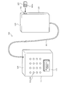
- FIG. 1 is an explanatory diagram illustrating a direct call support device according to an embodiment of the present invention.
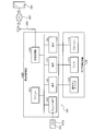
- FIG. 2 is an explanatory diagram illustrating an example of a hardware configuration of the direct call support device according to the embodiment of the present invention.
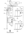
- FIG. 3 is an explanatory diagram illustrating an example of a configuration of an elevator to which the direct communication device according to the embodiment of the present invention is applied.
- FIG. 4 is a flowchart illustrating an example of a processing procedure of the direct call support device according to the embodiment of the present invention.
- FIG. 1 is an explanatory diagram illustrating a direct call support device according to an embodiment of the present invention.
- a direct call support device 100 according to an embodiment of the present invention includes a terminal device 110 in a car and a communication control device 120.
- the in-car terminal device 110 includes a housing 111 having a substantially rectangular parallelepiped shape, and is installed in a car of an elevator (see FIG. 3).
- the in-car terminal device 110 includes a call operation receiving unit 112, a microphone 113, and a speaker 114.
- the call operation receiving unit 112, the microphone 113, and the speaker 114 are provided on one surface of the housing 111 of the in-car terminal device 110.
- the call operation receiving unit 112 receives a user's call operation.
- the call operation receiving unit 112 can be realized by, for example, a push button switch.
- the push button switch includes an operation unit (push button) protruding from the housing, and can be operated (pushed) so as to push the operation unit into the inside of the housing.
- the push button switch is, for example, a normally open type in which the push button is biased in a direction protruding outside the housing and can be pushed into the inside of the housing only during operation.
- Momentary pushbutton switches can be used.
- the push button switch will be described with reference numeral 112.
- the microphone 113 collects the sound in the basket.
- a moving coil type microphone 113 including a diaphragm (diaphragm), a moving coil, and a magnet can be used.
- the microphone 113 is, specifically, a ribbon-type microphone 113 having a structure in which a ribbon formed by folding a thin metal foil made of aluminum or the like is hung between slits sandwiched by magnetic poles. There may be.
- Speaker 114 outputs sound into the basket.
- the speaker 114 can be realized by, for example, a dynamic speaker including a magnet, a speaker cone, a voice coil, and the like.
- the communication control device 120 is connected to the in-car terminal device 110.
- the communication control device 120 and the in-car terminal device 110 are connected by wire, for example, via the wiring 101.
- the in-car terminal device 110 and the communication control device 120 can be electrically connected to each other using a part of the conductors constituting the tail cord provided in the elevator as the wiring 101.
- the wiring 101 that connects the communication control device 120 and the in-car terminal device 110 connects, for example, an elevator car and an elevator control board, and supplies electric power to each unit provided in the car.
- a remainder line in the tail code (see FIG. 3) used for transmitting the control signal can be used.
- the communication control device 120 includes a SIM card slot 122 for receiving insertion of a SIM (Subscriber Identity Module) card 121.
- SIM Subscriber Identity Module
- the SIM card slot 122 is provided in a casing 123 of the communication control device 120 that is separate from the in-car terminal device 110.
- the SIM card slot 122 has a slot terminal connected to the IC chip 121a of the inserted SIM card 121 (see FIG. 2).
- the SIM card 121 includes an IMSI (International Mobile Subscriber Identity), an MSISDN (Mobile Subscriber Integrated Integrated Services Digital Network Network Number), and an ICCID (IntegratedCertificate such as an integrated IDC).
- IMSI International Mobile Subscriber Identity
- MSISDN Mobile Subscriber Integrated Integrated Services Digital Network Number
- ICCID IntegratedCertificate such as an integrated IDC
- IMSI indicates a unique ID number (identification information) for specifying a telephone number assigned to each direct call support device 100 (SIM card 121).
- the IMSI is a 15-digit identification number and is used together with the key information stored in the SIM card 121 for authentication for connecting to the network of the corresponding carrier.
- MSISDN is configured by a number within 15 digits, and indicates a so-called mobile phone number.
- the IMSI or MSISDN is issued by a regulatory authority and given to the carrier.
- the ICCID is composed of 19- or 20-digit characters or numbers, and indicates the serial number of the SIM card 121 itself.
- FIG. 2 is an explanatory diagram illustrating an example of a hardware configuration of the direct call support device 100 according to the embodiment of the present invention.
- the direct call support device 100 includes a car terminal device 110 and a communication control device 120.
- the in-car terminal device 110 includes the push button switch 112, the microphone 113, and the speaker 114 as described above.
- the push button switch 112 has a switch circuit (not shown) having a contact that can be opened and closed inside the housing.
- the contacts of the switch circuit are normally open and form a closed circuit when the pushbutton switch 112 is operated.
- the push button switch 112 outputs an ON signal or an OFF signal to the communication control device 120 according to the open / close state of the switch circuit.
- the microphone 113 performs analog-to-digital conversion of a voice such as a speaker's voice input as analog data, and generates digital-format voice data. Then, the microphone 113 outputs the generated digital audio data to the communication control device 120.
- the speaker 114 receives the input of the digital audio data output from the communication control device 120.
- the speaker 114 performs digital / analog conversion of the digital audio data output from the communication control device 120 and energizes a voice coil based on the analog audio data to vibrate the speaker cone and output audio.
- the communication control device 120 includes a terminal 201, a slot terminal 202, a microcomputer (microcomputer) 203, a transmission / reception circuit 204, and an antenna 205.
- the terminal 201 is connected to the push button switch 112, the microphone 113, and the speaker 114, respectively.
- a terminal 201 connected to the push button switch 112 outputs a signal output from the push button switch 112 to the microcomputer 203.
- a terminal 201 connected to the microphone 113 outputs a signal output from the microphone 113 to the microcomputer 203.
- a terminal 201 connected to the speaker 114 outputs a signal output from the microcomputer 203 to the speaker 114.
- the slot terminal 202 comes into contact with (the IC chip 121a of) the SIM card 121 inserted into the SIM card slot 122, and under the control of the microcomputer 203, the IMSI or MSISDN stored in (the IC chip 121a of) the SIM card 121. And the like, and outputs the read data to the microcomputer 203.
- the microcomputer 203 includes a CPU (Central Processing Unit) and a memory.
- the CPU directly controls the entire call support device 100.
- the memory stores various programs and various data tables. Specifically, the memory stores, for example, a program for making a call to a predetermined voice communication terminal device 210 and a telephone number (MSISDN or the like) of the voice communication terminal device (predetermined voice communication terminal device) 210 to be called. A data table to be stored is stored.
- the voice communication terminal device 210 to be called can be realized by, for example, a portable telephone carried by an operator of a maintenance management company that performs maintenance management of the elevator.
- the voice communication terminal device 210 to be called is not limited to, for example, a portable telephone carried by an operator of the maintenance company, but may be a telephone installed in a call center of the maintenance company.
- the number of telephone numbers stored in the memory as the voice communication terminal device 210 to be called may be a single number or a plurality.
- priority may be set for each telephone number.
- each telephone number may be stored in association with a time zone in which communication with the terminal device to which the telephone number is assigned is possible.
- the memory is used as a work area of the CPU.
- the memory can be realized by, for example, a read-only memory (ROM), a random access memory (RAM), a solid-state drive (SSD) including a NAND memory and a NAND memory controller that controls the NAND memory. .
- ROM read-only memory
- RAM random access memory
- SSD solid-state drive
- the microcomputer 203 includes a PB sending circuit (or a program) for outputting a PB (Push Button) signal (tone signal, push signal) by DTMF (Dual-Tone @ Multi-Frequency) to the transmitting / receiving circuit 204.
- PB Push Button
- DTMF Dual-Tone @ Multi-Frequency
- the transmission / reception circuit 204 includes a modulation / demodulation circuit, an oscillator, an amplification circuit, a filter, and the like (all are not shown).
- the transmission / reception circuit 204 is controlled by the microcomputer 203, and modulates digital audio data output from the microphone 113 and input via the terminal 201 in the modulation / demodulation circuit.
- the oscillator oscillates at the frequency of the RF signal that can be used for wireless communication.
- the amplifier circuit amplifies the power of the RF signal.
- the filter outputs a signal from which unnecessary frequency components have been removed to the antenna 205.
- the antenna 205 radiates a radio wave based on the signal output from the transmission / reception circuit 204 into space.
- the communication control device 120 is connected to the telephone network 200 via the antenna 205.
- the transmission / reception circuit 204 amplifies a signal received directly from the outside of the communication support apparatus 100 via the antenna 205 by an amplifier circuit and outputs the signal to a filter.
- the filter extracts a desired signal from the signal output from the amplifier circuit and outputs the extracted signal to the modulation / demodulation circuit.
- the modulation / demodulation circuit demodulates the signal output from the filter into digital audio data.
- the microcomputer 203 outputs digital audio data obtained by demodulating a signal received from the outside (the telephone network 200) to the speaker 114 in a state where the call by the call is established. As a result, a voice such as the voice of the speaker of the call destination can be output from the speaker 114.
- the communication control device 120 realizes a call by a circuit switching method using a unique ID number such as an IMSI assigned to each direct call support device 100 (SIM card 121 provided in the communication control device 120).
- SIM card 121 provided in the communication control device 120.
- the communication control device 120 may include a wireless LAN interface and implement a call by a packet switching method using an Internet line.
- the direct call support device 100 including the communication control device 120 for making a call by the packet switching method can transmit and receive image data in addition to the call.
- FIG. 3 is an explanatory diagram illustrating an example of a configuration of an elevator to which the direct communication device according to the embodiment of the present invention is applied.
- the elevator 300 can be realized by a rope type (traction type) elevator, for example.
- the elevator 300 is installed in a building such as a multi-storey building, for example. Each part of the elevator 300 is driven and controlled by a control panel 301.
- the control panel 301 is connected to each section of the elevator 300, and outputs a signal from the control panel 301 to each section of the elevator 300, that is, a so-called “down signal”.
- the control panel 301 receives, for example, a signal to the control panel 301 from each unit included in the elevator 300, a so-called “up signal”.
- the elevator 300 is provided with a hoistway (not shown) penetrating each floor of the building along the vertical direction.
- a hoistway (not shown) penetrating each floor of the building along the vertical direction.
- One hoistway is provided for each elevator 300.
- a basket (riding basket) 302 on which people and articles are mounted.
- the car 302 is provided one for each elevator 300, that is, one hoistway, and moves up and down along the direction of the hoistway, that is, the vertical direction.
- the basket 302 is supported by a basket frame (not shown), and moves up and down together with the frame.
- a guide rail (not shown) is provided on the side surface of the hoistway to guide the position of the car 302 (car frame).
- a shock absorber 303 for cushioning an impact when the basket 302 falls and collides with the bottom surface.
- the buffer 303 may be provided also on the ceiling surface of the hoistway.
- a door 304a is provided at a position (a landing) 304 corresponding to each floor in the hoistway.
- the door 304a provided at the landing 304 is locked by a device called an interlock (not shown).
- the interlock releases the lock by engaging with the opening / closing mechanism of the door 302a of the car 302 only when the motor that opens and closes the door 302a of the car 302 is driven while the car 102 arrives at the stop floor.
- a control panel 305 is installed at each landing 304, respectively.
- the operation panel 305 includes a hall call button 305a, a display 305b for displaying the floor where the car 302 is located, and the like.
- Each of the operation panels 305 includes a control board 305c for the operation panel 305.
- Each operation panel 305 is connected to the control panel 301 via a control board 305c provided for each operation panel.
- the basket 302 is connected to one end of the rope 306.
- the rope 306 is hung on a pulley (not shown) and a hoisting machine (traction machine) 307 in a slidable manner, and the other end is connected to the counterweight 308.
- the hoisting machine 307 in the rope-type elevator 300 is installed, for example, in a machine room provided at the uppermost part of the elevator 300.
- the hoisting machine 307 can be provided at the top of the elevator 300 regardless of the presence or absence of the machine room. Alternatively, when the elevator 300 is of a type having no machine room, the hoisting machine 307 may be provided at a lower part of the elevator 300.
- the hoisting machine 307 is connected to the control panel 301 via, for example, an inverter, and is driven and controlled by the control panel 301 so as to stop rotation on the floor where the car 302 is stopped.
- the hoist 307 includes an encoder (not shown), and the control panel 301 can determine the rotational speed and the rotational position of the hoist 307 based on an output signal from the encoder.
- the elevator 300 includes an electromagnetic brake 309, a governor (governor machine) 310, a limit switch 311 and the like.
- the electromagnetic brake 309 has a coil, and is driven and controlled by the control panel 301 to stop the rotation of the hoist 307 by using an electromagnetic force generated by energizing the coil.
- the electromagnetic brake 309 can maintain a state in which the rotation of the hoist 307 is stopped.
- the electromagnetic brake 309 stops the rotation of the hoist 307 when the power supply is stopped due to a power failure or the like.
- the electromagnetic brake 309 uses a non-excitation type electromagnetic brake 309 that operates by the force of a spring to stop rotation of the hoisting machine 307 when the power supply to the coil is cut off, for example, during a power failure. be able to.
- the governor 310 detects excess speed of car 302.
- the governor 310 can be realized by, for example, a centrifugal governor including a governor rope 310a, a governor pulley 310b, a rotating weight (not shown), and the like.
- the limit switch 311 includes a switch lever (not shown) for switching between supply and cutoff of power to the hoisting machine 307.
- the switch lever is positioned to supply power to the hoist 307 in normal times, and shuts off power supply to the hoist 307 when biased by the rotating weight of the governor 310. Displace to position.
- the elevator 300 may include an emergency stop device not shown.
- the basket 302 is provided with an operation panel 302b.
- the operation panel 302b is provided with various operation buttons and a display 302c for displaying a floor on which the car 302 is located.
- the display 302c may be realized by a seven-segment display that displays only the floor, or may be realized by a liquid crystal display that can display an image.
- the display 302c is not limited to the one provided in the cage 302 in advance, and may be one that is attached after the elevator 300 is installed.
- the basket 302 is provided with a motor for opening and closing the door 302a, a door opening / closing sensor, an obstacle detection device, various sensors such as a load sensor, a buzzer (all not shown), and the like.
- a basket upper box 312 is provided above the basket 302.
- the car upper box 312 is provided, for example, on a ceiling plate of the car 302, that is, outside the car 302.
- the car upper box 312 houses a board that forms an electric circuit including a power supply circuit and a control circuit (not shown).
- tail cord 313 is connected to the basket upper box 312.
- the tail cord 313 is composed of a plurality of conductors. The other end of some of the conductors is connected to a power supply, and the other end of some of the other conductors is connected to the control panel 301.
- power can be supplied to each unit provided in the basket 302 and a control signal can be transmitted.
- Various loads provided on the car 302 such as the operation panel 302b, a motor for opening and closing the door 302a, a door opening / closing sensor, an obstacle detection device, a load sensor, and various buzzers, are provided on the car upper box 312. Is electrically connected to the electric circuit.
- a relay, a transformer, an inverter, or the like may be interposed between the various loads provided on the car 302 and the electric circuit.
- the in-car terminal device 110 of the direct call support device 100 is provided in the car 302 of the elevator 300. Specifically, the in-car terminal device 110 is provided, for example, near the operation panel 302b.
- the communication control device 120 in the direct call support device 100 is provided at a position where radio waves can be transmitted and received by the antenna 205. Specifically, the communication control device 120 can be provided, for example, near the control panel 301 or at the top of the elevator 300.
- the direct call support device 100 may include a backup battery 314.
- the backup battery 314 can be provided, for example, in the upper basket box 312 or in the vicinity of the upper basket box 312. In this case, for example, one end (the end on the side of the upper box of the cage) of a part of the plurality of conductors constituting the tail cord 313 is connected to the backup battery 314 and the backup battery 314 is connected thereto. Power may be directly supplied to the communication support device 100 by using
- power can be directly supplied to the call support device 100 without separately providing an adapter for converting an AC voltage to a DC voltage, and when the power is externally supplied to the elevator 300, the power is supplied to the backup device.
- the battery 314 can be performed.
- a circuit or a program for switching the power supply when power supply from the outside to the elevator 300 is stopped can be used. Instead, power supply to the call support device 100 can be directly continued.
- FIG. 4 is a flowchart illustrating an example of a processing procedure of the direct call support device 100 according to the embodiment of the present invention.
- step S401 the process waits until it is determined that the push button switch 112 has been long-pressed (step S401: No).
- step S401 when the push button switch 112 is pressed for a long time (step S401: Yes), the telephone number assigned to the voice communication terminal device 210 of the call destination is acquired with reference to the memory (step S402).
- step S403 a call is made to the voice communication terminal device 210 to which the telephone number is assigned, using the telephone number obtained in step S402 as a call destination (step S403).
- step S403 communication is performed with the base station (radio base station) that is closest to the direct call support device 100 among the base stations (wireless base stations) configuring the mobile phone network constructed by the communication carrier.
- the base station that has accepted the call from the voice communication terminal device 210 communicates with the base station closest to the call destination voice communication terminal device 210 via the telephone network 200.
- the base station closest to the call destination voice communication terminal device 210 causes the call destination voice communication terminal device 210 to output a ringing tone.
- the base station closest to the call destination voice communication terminal device 210 outputs a ringing tone (RingBack @ Tone: RBT) to the direct call support device 100.
- the base station closest to the call destination voice communication terminal device 210 When the base station closest to the call destination voice communication terminal device 210 receives the terminal response signal indicating that the call is received at the call destination voice communication terminal device 210, the base station outputs the RBT to the direct call support device 100. Is stopped, and a signal is transmitted to the base station closest to the direct call support device 100 to notify that the voice communication terminal device 210 of the call destination has answered.
- the base station closest to the direct call support apparatus 100 communicates between the direct call support apparatus 100 and the call destination voice communication terminal 210 based on a signal indicating that the call destination voice communication terminal apparatus 210 has answered. To establish.
- step S404 stands by until a call is established between the direct call support device 100 and the call destination voice communication terminal device 210 due to the call made in step S403 (step S404: No).
- step S404 when the call is established (step S404: Yes), the process stands by until the established call is disconnected (step S405: No).
- wireless communication is performed directly with the base station closest to the call support device 100 via the antenna 205, so that voice data based on the sound collected by the microphone 113 is transmitted to the telephone line.
- voice based on the voice data received from the telephone line network 200 is output from the speaker 114.
- an image of an operator of a maintenance management company as a communication partner may be displayed on the display 302c of the basket 302. This allows the user who is trapped in the basket 302 of the elevator 300 to be notified of the rescue situation together with the image of the operator of the maintenance management company, so that the user can be relieved and calmed down. .
- the image of the operator is not limited to the one displayed on the existing display 302c.
- a display device such as a liquid crystal display may be installed in the cage 302 separately from the display device 302c that displays the floor where the basket 302 is located, and an image of the operator may be displayed on the display device.
- This display device may be provided on the housing 111 of the in-car terminal device 110.
- an information terminal device having a display screen may be installed in the basket 302, and an image of the operator may be displayed on the display screen of the information terminal device.
- the in-car terminal device (direct call support device) according to the present invention may be realized by a microphone and a speaker included in the information terminal device.
- step S405 when the call established in step S404: Yes is disconnected (step S405: Yes), a series of processing ends.
- step S405 for example, based on a disconnection signal (end signal) transmitted from the base station closest to the call destination voice communication terminal device 210 by ending the call in call destination voice communication terminal device 210.
- end signal end signal
- the call established in step S404: Yes is disconnected. You can judge.
- the in-car terminal device 110 and the communication control device 120 are separated from each other, and the in-car terminal device 110 and the communication control device 120 are separated from each other by a spare line of the tail code 313.
- the in-car terminal device 110 and the communication control device 120 may be provided integrally.
- the communication control device 120 is housed in the housing 111 of the in-car terminal device 110. In this case, only the antenna 205 may be provided outside the housing 111. Thereby, regardless of the radio wave reception environment in the car 302, a reliable direct sum can be realized.
- the communication control device 120 and the in-car terminal device 110 may be wirelessly connected.
- a communication device such as a transceiver is provided in both the communication control device 120 and the in-car terminal device 110.
- a backup battery 314 is connected to both the communication control device 120 and the in-car terminal device 110.
- the microphone 113 and the speaker 114 of the in-car terminal device 110 are not limited to those provided in the substantially rectangular housing 111.
- the microphone 113 and the speaker 114 are, for example, a microphone such as a telephone receiver that positions the microphone 113 at the mouth of the user in the basket 302 that directly talks and positions the speaker 114 at the ear of the user. It may be provided in a case having a shape.
- the push button switch 112 may be provided on a housing having a handset shape, or may be provided separately from the housing on the wall surface of the basket 302 or the operation panel 302b.
- the direct call support device 100 includes the in-car terminal device 110 and the communication control device 120.
- the in-car terminal device 110 includes a push button switch 112 for realizing a call operation receiving unit 112 for receiving a call operation of a user, a microphone 113 for collecting sound in the car 302, and a speaker for outputting sound in the car 302. 114 are installed in the basket 302 of the elevator 300.
- the communication control device 120 is connected to the in-car terminal device 110 and the telephone network 200, outputs voice data based on the voice collected by the microphone 113 to the telephone network 200, and receives the voice data from the telephone network 200. The sound based on the sound data is output from the speaker 114.
- the communication control device 120 makes a call to the predetermined voice communication terminal device 210 in accordance with the operation received by the call operation receiving portion 112, and when the call by the call is established, the sound is collected by the microphone 113.
- the voice data based on the received voice is output to the telephone network 200, and the voice based on the voice data received from the telephone network 200 is output from the speaker 114.
- a call from the communication control device 120 by a user in the car 302 of the elevator 300 operating the push button switch 112 is transmitted to the maintenance management company.
- a call can be made to a predetermined voice communication terminal device 210 carried by the operator, and a direct call (direct talk) between the user in the car 302 and the operator of the maintenance management company can be realized.
- the operator of the maintenance management company corresponding to the direct talk request from the user in the car 302 does not need to be resident at a fixed place such as the maintenance management company or the installation location of the elevator 300, and the user in the car 302
- the user can realize a direct talk between the user in the basket 302 and the operator of the maintenance management company at an arbitrary timing required by the user.
- the user in the basket 302 can directly communicate with the operator of the maintenance management company without providing a call center where the operator of the maintenance management company resides.
- the story can be realized easily and inexpensively.
- the direct call support device 100 of the embodiment according to the present invention even if the elevator 300 does not have the intercom device in the car 302 at the time of installation, the use in the car 302 after the installation of the elevator 300 is completed.
- a direct talk between the operator and the operator of the maintenance management company can be realized easily and at low cost. This makes it possible to easily and inexpensively realize the elevator 300 that can ensure the safety and convenience of the user.
- the communication control device 120 includes an antenna 205, and a base station (for example, a base station closest to the direct call support device 100) via the antenna 205.
- a base station for example, a base station closest to the direct call support device 100
- the communication control device 120 includes an antenna 205, and a base station (for example, a base station closest to the direct call support device 100) via the antenna 205.
- audio data based on the sound collected by the microphone 113 is output to the telephone network 200, and a sound based on the audio data received from the telephone network 200 is output to the speaker 114. It is characterized by being output from the.
- the direct call support device 100 of the embodiment according to the present invention even when a wired telephone line is not drawn into the premises where the elevator 300 is provided, the user in the car 302 and the operator of the maintenance management company Can be easily and inexpensively realized.
- the elevator 300 that can ensure the safety and convenience of the user of the elevator 300 can be easily and inexpensively realized.
- the in-car terminal device 110 connects the call operation receiving unit 112, the microphone 113, and the speaker 114 to a single unit installed in the car 302 of the elevator 300.
- the housing 111 Of the housing 111.
- the terminal device 110 in the car is attached to the car 302 of the existing elevator 300 not having the direct talk function, so that the existing elevator 300 A direct talk between the user in the basket 302 and the operator of the maintenance management company can be realized easily and at low cost.
- the communication control device 120 is separate from the in-car terminal device 110, and a part of a conductor constituting the tail cord 313 of the elevator 300. It is characterized by being connected to the in-car terminal device 110 using a conductor.
- the control panel 301 and the power supply of the elevator 300 are connected to each part provided in the car 302, and the communication between the control panel 301 and the car 302 and the car Using the tail cord 313 that supplies power to each unit provided in the 302, communication between the in-car terminal device 110 and the communication control device 120 and power supply to the in-car terminal device 110 can be performed.
- a backup battery 314 for supplying power to the in-car terminal device 110 is provided, such as on the ceiling plate of the car 302, such as a car upper box 312, and the power supply from the backup battery 314 is switched in the event of a power failure. You may. As a result, a user who is trapped in the basket 302 due to a power failure can surely talk directly with the operator of the maintenance management company, and the elevator 300 that can ensure the safety and convenience of the user of the elevator 300 can be easily provided. It can be realized at low cost.
- power may be directly supplied from the tail cord 313 to the call support device 100 via the backup battery 314.
- the power supply to the call support apparatus 100 can be directly continued without using a circuit or a program for switching the power supply.
- the direct call support device is useful for a direct call support device that supports a direct talk between a user in an elevator car and an operator of a maintenance management company. It is suitable for a direct call support device that supports a direct talk between a user in an elevator car not provided and an operator of a maintenance company.
- Direct call support device 110 Terminal device in cage 112 Call operation receiving unit (push button switch) 113 Microphone 114 Speaker 120 Communication control device 121 SIM card 200 Telephone network 201 Terminal 202 Slot terminal 203 Microcomputer 204 Transmission / reception circuit 205 Antenna 210 Voice communication terminal device
Landscapes
- Engineering & Computer Science (AREA)
- Signal Processing (AREA)
- Computer Networks & Wireless Communication (AREA)
- Business, Economics & Management (AREA)
- Emergency Management (AREA)
- Physics & Mathematics (AREA)
- General Physics & Mathematics (AREA)
- Indicating And Signalling Devices For Elevators (AREA)
- Alarm Systems (AREA)
- Interconnected Communication Systems, Intercoms, And Interphones (AREA)
- Telephone Function (AREA)
Abstract
L'invention concerne un dispositif de support d'appel direct 100 qui : appelle un dispositif terminal de communication vocale prescrit 210 si un interrupteur à bouton-poussoir 112 a été pressé sur un dispositif terminal embarqué 110 qui peut être installé ultérieurement à l'intérieur d'une cabine d'ascenseur ; et, si l'appel est connecté, délivre des données audio à un réseau téléphonique 200 par l'intermédiaire d'un dispositif de commande de communication 120, sur la base d'audio collecté par un microphone 113, et délivre l'audio depuis un haut-parleur 114 sur la base de données audio reçues en provenance du réseau téléphonique 200. Par conséquent, une communication directe entre un utilisateur à l'intérieur de la cabine d'ascenseur et un opérateur au niveau d'une entreprise de gestion de maintenance peut être obtenue facilement et de manière peu coûteuse.
Priority Applications (3)
| Application Number | Priority Date | Filing Date | Title |
|---|---|---|---|
| PCT/JP2018/025422 WO2020008579A1 (fr) | 2018-07-04 | 2018-07-04 | Dispositif de support d'appel direct |
| JP2020528616A JP7451401B2 (ja) | 2018-07-04 | 2018-07-04 | 直接通話支援装置 |
| JP2023080455A JP2023106487A (ja) | 2018-07-04 | 2023-05-15 | 直接通話支援装置 |
Applications Claiming Priority (1)
| Application Number | Priority Date | Filing Date | Title |
|---|---|---|---|
| PCT/JP2018/025422 WO2020008579A1 (fr) | 2018-07-04 | 2018-07-04 | Dispositif de support d'appel direct |
Publications (1)
| Publication Number | Publication Date |
|---|---|
| WO2020008579A1 true WO2020008579A1 (fr) | 2020-01-09 |
Family
ID=69060495
Family Applications (1)
| Application Number | Title | Priority Date | Filing Date |
|---|---|---|---|
| PCT/JP2018/025422 Ceased WO2020008579A1 (fr) | 2018-07-04 | 2018-07-04 | Dispositif de support d'appel direct |
Country Status (2)
| Country | Link |
|---|---|
| JP (2) | JP7451401B2 (fr) |
| WO (1) | WO2020008579A1 (fr) |
Families Citing this family (1)
| Publication number | Priority date | Publication date | Assignee | Title |
|---|---|---|---|---|
| CN112267147B (zh) * | 2020-09-29 | 2022-12-13 | 西安奕斯伟材料科技有限公司 | 单晶炉热场加热器及单晶炉 |
Citations (6)
| Publication number | Priority date | Publication date | Assignee | Title |
|---|---|---|---|---|
| JP2007001774A (ja) * | 2006-10-16 | 2007-01-11 | Hitachi Ltd | エレベータかご監視装置 |
| WO2008093980A1 (fr) * | 2007-01-30 | 2008-08-07 | Nntec Advertising Co., Ltd. | Système d'éclairage de secours pour ascenseur |
| JP2009190874A (ja) * | 2008-02-15 | 2009-08-27 | Toshiba Elevator Co Ltd | エレベータの通報システム |
| JP2011249860A (ja) * | 2010-05-21 | 2011-12-08 | Softbank Mobile Corp | 遠隔監視システム及びそのシステムに用いる通信アダプタ装置 |
| JP2016174316A (ja) * | 2015-03-17 | 2016-09-29 | ジャパンエレベーターサービスホールディングス株式会社 | エレベーターの通話管理システム |
| JP2017190225A (ja) * | 2016-04-14 | 2017-10-19 | フジテック株式会社 | エレベーターの通話システム及びエレベーター |
Family Cites Families (8)
| Publication number | Priority date | Publication date | Assignee | Title |
|---|---|---|---|---|
| US6341668B1 (en) * | 2000-04-03 | 2002-01-29 | Televator One, Llc | Interactive elevator communication system |
| JP2002226148A (ja) | 2001-01-31 | 2002-08-14 | Toshiba Elevator Co Ltd | エレベータの操作盤 |
| JP4241678B2 (ja) * | 2005-06-30 | 2009-03-18 | 三菱電機ビルテクノサービス株式会社 | エレベータ内交信制御システム及びエレベータ内交信制御プログラム |
| JP2009120371A (ja) | 2007-11-16 | 2009-06-04 | Toshiba Elevator Co Ltd | エレベータの非常時保守サービス情報提供システム及びその情報提供方法 |
| KR20130022990A (ko) * | 2011-08-26 | 2013-03-07 | (주)에이치피엔알티 | 승강기 통합 감시시스템 |
| JP2014172723A (ja) | 2013-03-08 | 2014-09-22 | Toshiba Elevator Co Ltd | エレベータの制御装置 |
| JP6249039B2 (ja) * | 2016-04-05 | 2017-12-20 | 三菱電機ビルテクノサービス株式会社 | エレベータシステム |
| JP6333505B1 (ja) * | 2018-01-17 | 2018-05-30 | ジャパンエレベーターサービスホールディングス株式会社 | エレベーター |
-
2018
- 2018-07-04 WO PCT/JP2018/025422 patent/WO2020008579A1/fr not_active Ceased
- 2018-07-04 JP JP2020528616A patent/JP7451401B2/ja active Active
-
2023
- 2023-05-15 JP JP2023080455A patent/JP2023106487A/ja active Pending
Patent Citations (6)
| Publication number | Priority date | Publication date | Assignee | Title |
|---|---|---|---|---|
| JP2007001774A (ja) * | 2006-10-16 | 2007-01-11 | Hitachi Ltd | エレベータかご監視装置 |
| WO2008093980A1 (fr) * | 2007-01-30 | 2008-08-07 | Nntec Advertising Co., Ltd. | Système d'éclairage de secours pour ascenseur |
| JP2009190874A (ja) * | 2008-02-15 | 2009-08-27 | Toshiba Elevator Co Ltd | エレベータの通報システム |
| JP2011249860A (ja) * | 2010-05-21 | 2011-12-08 | Softbank Mobile Corp | 遠隔監視システム及びそのシステムに用いる通信アダプタ装置 |
| JP2016174316A (ja) * | 2015-03-17 | 2016-09-29 | ジャパンエレベーターサービスホールディングス株式会社 | エレベーターの通話管理システム |
| JP2017190225A (ja) * | 2016-04-14 | 2017-10-19 | フジテック株式会社 | エレベーターの通話システム及びエレベーター |
Also Published As
| Publication number | Publication date |
|---|---|
| JP2023106487A (ja) | 2023-08-01 |
| JP7451401B2 (ja) | 2024-03-18 |
| JPWO2020008579A1 (ja) | 2021-08-05 |
Similar Documents
| Publication | Publication Date | Title |
|---|---|---|
| US9067760B2 (en) | Communication with an elevator system | |
| KR101855364B1 (ko) | 엘리베이터의 비상통화장치 | |
| US11250690B2 (en) | Security system for buildings with elevator installations | |
| CN111727163B (zh) | 用于具有目标呼叫控制器的电梯设备的成本低廉的电梯伺服装置 | |
| KR20210137153A (ko) | 엘리베이터의 자동 호출 등록 시스템 | |
| JP2023106487A (ja) | 直接通話支援装置 | |
| CN110182660B (zh) | 电梯系统 | |
| JP2014151998A (ja) | エレベータの遠隔監視装置 | |
| JP2017206326A (ja) | エレベータ用非常時利用者検知装置 | |
| JP6555173B2 (ja) | エレベータ装置 | |
| US11274016B2 (en) | Wireless communication in an elevator system | |
| WO2020008580A1 (fr) | Dispositif de support d'appel direct | |
| KR20130065973A (ko) | 이동통신 단말기를 이용한 엘리베이터 운전 제어 방법 | |
| JP7456046B2 (ja) | エレベーター状況通知端末装置 | |
| JP2665406B2 (ja) | エレベータの小電力無線機器装置 | |
| CN216450179U (zh) | 一种轿厢报警远程短信通知装置 | |
| JP7302064B2 (ja) | エレベーター状況表示端末装置 | |
| JP2005213032A (ja) | 携帯端末使用可能なエレベータ | |
| JP2022158263A (ja) | エレベーターの外部連絡装置 | |
| WO2019224928A1 (fr) | Dispositif d'aide à la surveillance à distance d'un ascenseur | |
| CN213112093U (zh) | 一种轿厢式电梯应急求救通信设备 | |
| CN108569601A (zh) | 一种电梯运行状态显示及通讯系统 | |
| JP2008063084A (ja) | エレベーターの遠隔監視システムならびに遠隔監視方法 | |
| CN118025916A (zh) | 电梯通信系统 | |
| EP4132872A1 (fr) | Appareils et procédés pour permettre un appel à un ascenseur dans une situation d'urgence |
Legal Events
| Date | Code | Title | Description |
|---|---|---|---|
| 121 | Ep: the epo has been informed by wipo that ep was designated in this application |
Ref document number: 18925214 Country of ref document: EP Kind code of ref document: A1 |
|
| NENP | Non-entry into the national phase |
Ref country code: DE |
|
| ENP | Entry into the national phase |
Ref document number: 2020528616 Country of ref document: JP Kind code of ref document: A |
|
| 122 | Ep: pct application non-entry in european phase |
Ref document number: 18925214 Country of ref document: EP Kind code of ref document: A1 |