WO2020008596A1 - ドアレール清掃装置、ドアレール清掃方法、及びエレベーター - Google Patents
ドアレール清掃装置、ドアレール清掃方法、及びエレベーター Download PDFInfo
- Publication number
- WO2020008596A1 WO2020008596A1 PCT/JP2018/025550 JP2018025550W WO2020008596A1 WO 2020008596 A1 WO2020008596 A1 WO 2020008596A1 JP 2018025550 W JP2018025550 W JP 2018025550W WO 2020008596 A1 WO2020008596 A1 WO 2020008596A1
- Authority
- WO
- WIPO (PCT)
- Prior art keywords
- door rail
- door
- cleaning device
- hanger
- foreign matter
- Prior art date
- Legal status (The legal status is an assumption and is not a legal conclusion. Google has not performed a legal analysis and makes no representation as to the accuracy of the status listed.)
- Ceased
Links
Images



Classifications
-
- B—PERFORMING OPERATIONS; TRANSPORTING
- B66—HOISTING; LIFTING; HAULING
- B66B—ELEVATORS; ESCALATORS OR MOVING WALKWAYS
- B66B13/00—Doors, gates, or other apparatus controlling access to, or exit from, cages or lift well landings
- B66B13/30—Constructional features of doors or gates
Definitions
- the present invention relates to a door rail cleaning device and a door rail cleaning method for cleaning a door rail for suspending and guiding a door in an elevator.
- the invention also relates to an elevator.
- the elevator includes a door rail for suspending and guiding a door installed in a car or a landing. Specifically, the door is suspended from a hanger, and a roller that moves on a door rail is rotatably attached to the hanger.
- a door rail cleaning device for cleaning a door rail for suspending and guiding a door in an elevator, wherein the door is fixed to a hanger on which the door is suspended. And a foreign matter removing unit that has a lower surface that comes into contact with an upper surface of the door rail when cleaning the door rail, and removes foreign matter on the door rail.
- the door rail cleaning device can be fixed to the hanger of the elevator in a state in which the lower surface of the foreign matter removing portion is in contact with the upper surface of the door rail and the foreign matter removing portion is disposed on the distal end side of the roller sliding on the rail. Further, with the door rail cleaning device fixed to the hanger in this manner, the door can be moved in the opening direction to the fully opened state, or can be moved from the fully opened state to the closing direction. Therefore, by the operation, it becomes possible to scrape the foreign matter accumulated at the end of the door rail by the foreign matter removing part and push it out of the door rail, or to stick the scraped foreign matter to the foreign matter removing part and carry it inside the door rail. . Therefore, the foreign matter located at the end of the door rail can be easily removed, and the door can be moved smoothly.
- the hanger fixing portion may be fixed to the hanger.
- the tip of the lower surface of the foreign matter removing portion can be projected outward from the tip on one side of the door rail. Therefore, it becomes easier to push out the foreign matter accumulated at the end of the door rail to the outside of the door rail, and it is possible to clean the door rail cleanly.
- the lubricating material is provided such that the foreign matter removing portion is provided on one side in the height direction so as to extend in a direction substantially orthogonal to the height direction, and is located on the other side in the height direction.
- a main body including a mounting portion, a lubricating material attached to the lubricating material mounting portion in a state in which a tip side protrudes from the main body to the other side in the height direction, and a lubricating material made of a material impregnable with oil; Holding part, and a holder having the hanger fixing part, and in a state where the hanger fixing part is fixed to the hanger, the other side in the height direction of the holding part is downward. It may be possible to take a first state in which the main body is held in a state in which the main body is held, and a second state in which the main body is held in a state in which one side in the height direction of the holding portion is on the lower side.
- the upper end of the door rail in the first state, can be lubricated with the oil impregnated in the lubricating material by bringing the lower end of the lubricating material attached to the lubricating material mounting portion into contact with the upper surface of the door rail. . Therefore, by setting the elevator in the first state during normal operation, the door rail cleaning device can be used as a fuel supply device during normal operation, and the roller is easily rotated and moved on the door rail smoothly.
- the lower surface of the foreign matter removing portion in the second state, can be brought into contact with the upper surface of the door rail, and the foreign matter removing portion can be disposed on the tip side of the roller. Therefore, when the door rail is cleaned, the foreign substance on the door rail can be removed by moving the door in the opening direction in the second state in the opening state or in the closing direction from the fully open state in the second state.
- the door rail can always be lubricated with oil from the lubricating material, and the foreign matter removing portion can be held above the lubricating material without contacting the door rail. Therefore, it is not necessary to bring the door rail cleaning device when cleaning the door rail, and the door rail can be cleaned only by turning over the main body and holding the main body in the holding portion. Therefore, the convenience of handling the door rail cleaning device can be improved.
- the lubricating material mounting portion is a housing recess having an opening on the other side in the height direction, and the lubricating material is provided in the housing portion housed in the housing recess and the height from the opening.
- the main body has a bottom plate portion on one side in the height direction, the bottom plate portion constituting a bottom portion of the housing recess, and the bottom plate portion communicates with the housing recess. May be provided.
- the lubricating material can be easily and reliably attached to the main body only by housing the lubricating material housing portion in the housing recess by press fitting or the like.
- the lubricating material since most of the outer surface of the housing portion can be covered with the inner surface of the housing recess when the lubricating material is attached, drying and volatilization of the oil impregnated in the lubricating material can be suppressed.
- a through-hole is provided in the bottom plate constituting the bottom of the housing recess, when the elevator is operating normally and the lubricating material is in contact with the upper surface of the door rail, the lubricating oil is removed using a dropper or the like. The oil can be supplied from the upper side to the storage portion for the lubricating material via the through hole. Therefore, the lubricating oil can be easily replenished to the lubricating material without removing the cleaning device from the hanger.
- the apparatus further comprises a hanger mounting portion mounted on the hanger, and a pressing structure having a pressing portion extending in a height direction, wherein the pressing portion is mounted on the refueling material mounting portion in the second state.
- the foreign material removing portion may be pressed against the upper surface by pressing the lubricating material to one side in the height direction.
- the foreign matter removing portion can be pressed against the upper surface of the door rail by the pressing structure in the second state. Therefore, the lower surface of the foreign matter removing portion can be brought into close contact with the upper surface of the door rail during cleaning, and foreign matter on the door rail can be effectively removed.
- a door rail cleaning method is a door rail cleaning method for cleaning a door rail for suspending and guiding a door in an elevator using the door rail cleaning device of the present invention, wherein the door rail cleaning device is provided when the door is fully opened. Fixing the hanger fixing portion to the hanger such that a part of the lower surface of the foreign matter removing portion contacts the upper surface of the door rail and a tip of the lower surface protrudes outward from one end of the door rail. And a moving step of moving the door in the opening direction to the fully opened state after the fixing step.
- the elevator according to the present invention includes the door rail cleaning device of the present invention.
- the tip of the lower surface of the foreign matter removing portion can be projected outward from the tip on one side of the door rail. Therefore, it is easy to push out the foreign matter accumulated at the end of the door rail to the outside of the door rail, and it is possible to clean the door rail neatly.
- the door rail cleaning device According to the door rail cleaning device, the door rail cleaning method, and the elevator according to the present invention, it is easy to easily remove foreign matter accumulated at the end of the door rail.
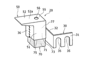
- FIG. 3 is a perspective view of the cleaning device when viewed from a direction indicated by an arrow A in FIG. 2. It is a perspective view of the holder of a cleaning device.
- FIG. 4 is a perspective view corresponding to FIG. 3 of a cleaning device in which a holder holds a main body upside down in comparison with the case illustrated in FIG. 3.
- FIG. 3 is an enlarged perspective view corresponding to FIG. 2 of an elevator in which a cleaning operation is being performed.
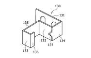
- It is a perspective view of the holder of a modification.
- FIG. 1 is a schematic front view when the car door 2 of the elevator 1 is viewed from the landing side, and is a diagram for explaining the operation of the pair of doors 2a and 2b of the car door 2.
- the basket 5 has a door rail 6 that extends in the width direction of the entrance above the entrance.
- the doors 2a, 2b are suspended by hangers 4a, 4b, and rollers 7a, 7b rotatably moving on the door rail 6 are rotatably attached to the hangers 4a, 4b.
- the elevator 1 further includes first and second pulleys 8a and 8b and an endless belt 9.
- Each of the first and second pulleys 8a, 8b is arranged to face each other in the width direction such that the rotation axis extends in the normal direction of the car door 2, and the first pulley 8a is rotated by the power of the motor 10. .
- the endless belt 9 is stretched over the first and second pulleys 8a and 8b, and circulates when the motor 10 is driven.
- One hanger 4a is fixed to an upper portion 9a that moves in the width direction on the upper side during the circulating movement of the endless belt 9, and the other hanger 4b is positioned below the upper portion 9a and circulates the endless belt 9. Sometimes it is fixed to a lower part 9b which moves on the opposite side to the upper part 9a.
- the endless member circulating is the endless belt 9, but the endless member may be an interlocking rope (loop-shaped metal wire).
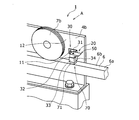
- FIG. 2 is an enlarged perspective view showing the periphery of the hanger 4b in the longitudinal direction of the elevator 1 which is operating normally.
- the elevator 1 includes a door rail cleaning device (hereinafter, simply referred to as a cleaning device) 20 attached to the hanger 4b, and the cleaning device 20 includes a holder 30, a main body 50, and a lubricating material 70.
- the holder 30 is formed of a metal flat plate that is bent in a substantially orthogonal direction at a plurality of positions, and is fixed to the rail side surface 12 of the hanger 4b with bolts 11.
- the holder 30 includes a first flat plate portion 31, a second flat plate portion 32, a third flat plate portion 33, and a fourth flat plate portion 34 as an example of a hanger fixing portion, and the back surface of the first flat plate portion 31 , Are arranged so as to contact the rail side surface 12.
- the first flat plate portion 31 has a concave portion or a through hole penetrating in the thickness direction. After passing the shaft portion of the bolt 11 through the concave portion or through hole, the first flat plate portion 31 is fixed to the hanger 4b by tightening the bolt 11 into the hanger 4b.
- the second flat plate portion 32 extends from the end of the first flat plate portion 31 on the side opposite to the roller 7b side substantially in the normal direction of the rail side surface 12.
- the third flat plate portion 33 extends in the direction in which the door rail 6 extends from the end of the second flat plate portion 32 opposite to the first flat plate portion 31 to the opposite side to the first flat plate portion 31.
- the fourth flat plate portion 34 extends from the end of the third flat plate portion 33 opposite to the second flat plate portion 32 toward the rail side surface 12 in substantially the normal direction.
- the main body 50 is made of, for example, a metal such as aluminum or steel, or a hard resin such as ABS resin or polycarbonate.
- the main body 50 has a mounting portion that is housed in a recess surrounded on three sides by the second to fourth flat plate portions 32 to 34.
- the attachment portion is attached to the concave portion, and as a result, the main body 50 is indirectly attached to the hanger 4b via the holder 30, and stands still with respect to the hanger 4b.
- the lubricating material 70 is made of a material that can be impregnated with oil, and is made of, for example, a felt, a sponge, a brush, or the like.
- the lubricating material 70 is impregnated with a lubricating oil.
- the lubricating material 70 is attached to the main body 50. The mounting structure of the mounting portion to the concave portion and the mounting structure of the lubricating material 70 to the main body 50 will be described later in detail.
- the lubricating material 70 has a projection 71 projecting downward from the main body 50 in a state attached to the main body 50, and a lower end portion of the projection 71 contacts the upper surface of the door rail 6.
- the protrusion 71 slides on the upper surface of the door rail 6 in the extending direction of the door rail 6, so that the upper end 6a of the door rail 6 is lubricated with oil impregnated in the lubricating material 70, As a result, the roller 7b can smoothly move on the door rail 6.
- FIG. 3 is a perspective view when the cleaning device 20 is viewed from the direction indicated by the arrow A in FIG.
- the main body 50 includes a column 51 formed of a column such as a rectangular parallelepiped, and a scraper 52 provided on one side of the column 51 in the height direction.
- the scraper section 52 is an example of a foreign substance removing section, and extends in a direction substantially perpendicular to the height direction of the column section 51.
- a bottom surface 52a on one side in the height direction of the scraper portion 52 is a flat surface, and the bottom surface 52a extends in a direction substantially orthogonal to the height direction of the cleaning device 20.
- the scraper portion 52 has a spatula shape, and more specifically, has a sharp blade shape whose thickness becomes smaller as it goes to the tip side in the orthogonal direction. Since the scraper section 52 has a sharp blade shape, the scraper section 52 is moved relative to the plane while the bottom surface 52a of the scraper section 52 is in contact with the plane. The adhered or deposited foreign matter can be scraped off and the plane can be cleaned.
- the column 51 has an accommodation recess 73 as an example of a lubrication material attachment portion.
- the accommodation recess 73 extends in the height direction and opens only on the other side in the height direction.
- the lubricating material 70 is attached to the housing recess 73 by press-fitting or the like in a state where the tip side protrudes from the housing recess 73 to the other side in the height direction.
- the lubricating material 70 may be detachable from the main body 50, or may be fixed to the main body 50 with an adhesive or the like.
- the refueling material 70 has a housing portion 77 housed in the housing recess 73, and a protrusion 71 projecting from the opening 75 of the housing recess 73 to the other side in the height direction. Further, the main body 50 has a bottom plate portion 55 that constitutes the bottom of the housing recess 73 on one side in the height direction. The bottom plate 55 is provided with a through hole 56 communicating with the housing recess 73.
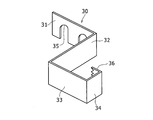
- FIG. 4 is a perspective view of the holder 30.
- the holder 30 includes the above-described first to fourth flat plate portions 31 to 34, and the first flat plate portion 31 is provided with one or more concave portions 35.
- the concave portion 35 opens on one side in the height direction and penetrates the first flat plate portion 31 in the thickness direction.
- the holder 30 further includes a locking claw 36.
- the locking claw 36 protrudes from the end of the fourth flat plate portion 34 opposite to the third flat plate portion 33 toward the second flat plate portion 32.
- the first to fourth flat plate portions 31 to 34 and the locking claw 36 have the same height. Referring again to FIG. 3, the fourth flat plate portion 34 and the locking claw 36 are distorted so as to deform the locking claw 36 toward the fourth flat plate portion 34, and the side surface of the main body 50 is locked with the locking claw. 36 and pressed from both sides while being sandwiched by the second flat portion 32. With this pressing force, the main body 50 is held by the holder 30.
- the second to fourth flat plate portions 32 to 34 and the locking claw 36 form a holding portion that holds the main body 50.
- the holder 30 is made of a band-shaped metal material having a plurality of bent portions, and the main body 50 has a column portion 51 extending in the height direction.
- the main body 50 can be held by the holder 30 in a state where the height direction of the column portion 51 is reversed in comparison with FIG.
- the shaft portion of the bolt 11 is inserted into the concave portion 35 of the holder 30, and then tightened to the hanger 4 b so that the bottom surface 52 a of the scraper portion 52 is placed on the upper surface of the door rail 6.
- the cleaning device 20 can be fixed to the hanger 4b in a state where the cleaning device 20 is in contact with the hanger 4b.
- the holder 30 in a state in which the holder 30 is fixed to the hanger 4 b, a state in which the other side in the height direction of the holder is lower (a state in which the refueling material 70 is lower).
- the first state of holding the main body 50 can be taken.
- the holder 30 holds the main body 50 in a state where the holding part is in a state where one side in the height direction is on the lower side (in a state where the scraper part 52 is on the lower side). It can take two states.
- the lubricating material 70 can be slid in the extending direction of the door rail 6 with respect to the upper surface 6b of the door rail 6, and the upper end of the door rail 6
- the portion 6a can be lubricated with the oil impregnated in the lubricating material 70.
- foreign substances attached to the upper surface 6b of the door rail 6 can be scraped off by the scraper portion 52, and the upper surface 6b of the door rail 6 can be cleaned.
- the hanger 4b has a mounting hole for mounting the cleaning device 20.
- the bolt 11 is screwed into the mounting hole via the recess 35, and as a result, the cleaning device 20 is fixed to a predetermined position of the hanger 4b.
- the elevator 1 is configured such that the tip of the scraper portion 52 is located outside the tip of the door rail 6. Has become.
- another cleaning device 20 is attached to the hanger 4a outside the roller 7a.
- the cleaning device 20 is used for cleaning the door rail 6 that suspends and guides the doors 2a and 2b in the elevator 1. Further, the cleaning device 20 contacts the first flat plate portion (hanger fixing portion) 31 fixed to the hangers 4a, 4b on which the doors 2a, 2b are suspended, and the upper surface 6b of the door rail 6 when cleaning the door rail 6.
- a scraper section (foreign matter removing section) 52 having a bottom surface (lower surface) 52a for scraping foreign matter on the door rail 6 is provided.
- the cleaning device 20 is mounted on the hanger of the elevator 1 in a state where the bottom surface 52a of the scraper portion 52 is in contact with the upper surface 6b of the door rail 6 and the scraper portion 52 is disposed on the tip side of the rollers 7a and 7b sliding on the door rail 6. 4a, 4b. Further, with the cleaning device 20 fixed to the hangers 4a, 4b in this manner, the doors 2a, 2b can be moved in the opening direction to the fully opened state, or can be moved from the fully opened state to the closing direction.
- the foreign matter accumulated at the end of the door rail 6 can be scraped off by the scraper portion 52 and pushed out of the door rail 6, or the scraped foreign matter can be attached to the scraper portion 52 and carried inside the door rail 6. Will be possible. Therefore, the foreign substances located at the end of the door rail 6 which are difficult to reach by the conventional cleaning work and are difficult to remove are easily removed, and the doors 2a and 2b can be moved smoothly.
- One flat plate portion 31 may be fixed to the hangers 4a, 4b.
- the tip of the bottom surface 52a of the scraper portion 52 can be projected outward from the one end of the door rail 6. Therefore, it is easy to push out the foreign matter accumulated at the end of the door rail 6 to the outside of the door rail 6, and the door rail 6 can be cleaned cleanly.
- the cleaning device 20 may include a main body 50 provided so that the scraper portion 52 extends on one side in the height direction in a direction substantially orthogonal to the height direction.
- An accommodation recess (oil supply material attachment portion) 73 having a portion located on the other side may be included. Further, the cleaning device 20 is attached to the housing recess 73 in a state where the tip side protrudes from the main body 50 to the other side in the height direction, and holds the lubricating material 70 made of a material that can be impregnated with oil and the main body 50.
- a holder 30 having the first flat plate portion 31.
- the cleaning device 20 is configured such that the first flat plate portion 31 is fixed to the hangers 4a and 4b, and the main body 50 is in a state where the other side (the refueling material 70 side) in the height direction is lower. And a second state in which the main body 50 is held in a state in which the holding portion has one side in the height direction (the scraper portion 52 side) on the lower side.
- the lower end of the lubrication material 70 attached to the accommodation recess 73 is brought into contact with the upper surface 6 b of the door rail 6, so that the oil impregnated in the lubrication material 70 is used for the door rail 6.
- the upper surface 6b can be lubricated. Accordingly, by setting the elevator 1 in the first state during normal operation, the cleaning device 20 can be used as a refueling device during normal operation, and the rollers 7a and 7b can be easily rotated and moved on the door rail 6 smoothly.
- the bottom surface 52a of the scraper portion 52 can be brought into contact with the upper surface 6b of the door rail 6, and the scraper portion 52 can be disposed at a more distal end side than the rollers 7a and 7b. Therefore, at the time of cleaning the door rail 6, by removing the doors 2a, 2b in the second state in the opening direction from the fully opened state or moving the doors 2a, 2b from the fully opened state to the closing direction, the foreign matter on the door rail 6 can be removed. .
- the door rail 6 can be constantly lubricated with oil from the lubricating material 70, and the scraper portion 52 can be placed above the lubricating material 70 without contacting the door rail 6. Can be held. Therefore, it is not necessary to bring the cleaning device 20 when cleaning the door rail 6, and the door rail 6 can be cleaned only by turning the main body 50 upside down and holding the main body 50 on the holding portion of the holder 30. Therefore, the convenience of handling the cleaning device 20 can be improved.
- the lubricating material mounting portion may be a housing recess 73 having an opening 75 on the other side in the height direction.
- the lubricating material 70 may include a housing portion 77 housed in the housing recess 73 and a projecting portion 71 projecting from the opening 75 to the other side in the height direction.
- the main body 50 may have a bottom plate portion 55 that constitutes a bottom portion of the housing recess 73 on one side in the height direction. And the bottom plate part 55 may have the through-hole 56 which communicates with the accommodation recessed part 73.
- the lubricating material 70 can be easily and reliably attached to the main body 50 simply by housing the housing portion 77 of the lubricating material 70 in the housing recess 73 by press-fitting or the like.
- the housing portion 77 can be covered with the inner surface of the housing recess 73 when the lubricating material 70 is attached, drying and volatilization of the oil impregnated in the lubricating material 70 can be suppressed.
- the dropper The lubricating oil can be supplied to the housing portion 77 of the lubricating material 70 from above through the through-hole 56 by using the method described above. Therefore, the lubricating oil can be easily replenished to the lubricating material 70 without removing the cleaning device 20 from the hangers 4a, 4b.
- the door rail cleaning method according to the present disclosure is a cleaning method for cleaning the door rail 6 that suspends and guides the doors 2a and 2b in the elevator 1 using the cleaning device 20 according to the present disclosure.
- the door rail cleaning method when the doors 2a and 2b are fully opened, a part of the bottom surface 52a of the scraper portion 52 of the cleaning device 20 contacts the upper surface 6b of the door rail 6 and the tip of the bottom surface 52a is on one side of the door rail 6.
- the doors 2a, 2b are preferably moved at least one reciprocation, more preferably at least two reciprocations. In addition, if the doors 2a and 2b are moved more than 5 times in the moving step, even the foreign matter fixed on the upper surface 6b of the door rail 6 can be easily removed.
- the elevator 1 may include the cleaning device 20 according to the present disclosure.
- the elevator 1 when the doors 2 a and 2 b are fully open, a part of the bottom surface 52 a of the scraper portion 52 of the cleaning device 20 contacts the upper surface 6 b of the door rail 6 and the tip of the bottom surface 52 a is moved from one end of the door rail 6. It is preferable to project outward. In this case, foreign matters accumulated at the end of the door rail 6 can be easily pushed out of the door rail 6, and the door rail 6 can be cleaned cleanly.
- the cleaning device may have a structure that presses the scraper portion 52 downward in the second state.
- the cleaning device may further include a pressing structure 80 whose side view is shown in FIG. 7, and the pressing structure 80 may include a flat-plate-shaped magnet 81 as an example of a hanger mounting portion that is mounted on a hanger. Good.
- the pressing structure 80 may include a coil spring 83 as an example of a pressing portion connected to the magnet 81 via a connecting portion 82 to which the magnet 81 is fixed. The coil spring 83 may be able to extend in the vertical direction when attached.
- magnet 81 is attached to upper region 12 a located above lubrication material 70 of cleaning device 20 fixed to hanger 4 b on rail side surface 12 of hanger 4 b, and lubrication material is provided by coil spring 83. 70 may be pressed downward. By pressing the lubricating material 70 downward by the coil spring 83 in this way, the scraper portion 52 is pressed downward by the coil spring 83 via the lubricating material 70, and the bottom surface 52a of the scraper portion 52 is You may press on the upper surface 6b.
- the pressing structure 80 can press the bottom surface 52 a of the scraper portion 52 against the upper surface 6 b of the door rail 6 in the second state. Therefore, the bottom surface 52a of the scraper portion 52 can be brought into close contact with the upper surface 6b of the door rail 6, and foreign matter on the door rail 6 can be effectively removed.
- the hanger mounting portion is the magnet 81
- the hanger mounting portion includes a fastening member such as a bolt and a screw hole located above the lubricating material of the cleaning device fixed to the hanger on the rail side surface. May be included.
- the pressing portion is configured by the coil spring 83, the pressing portion may be configured by a rod-shaped portion. When the hanger mounting portion is mounted at a predetermined position of the hanger, the bar-shaped portion extends in the vertical direction. Is also good.
- the holder 30 may not have the structure shown in FIG.
- the structure shown in FIG. 8 may be used.
- the holder 130 includes a second flat plate portion 132 and a third flat plate portion 133 that are substantially parallel to the first flat plate portion 131 to be attached to the hanger, and a normal to the first flat plate portion 131. When viewed from the direction, all of the second flat plate portion 132 and the third flat plate portion 133 may overlap the first flat plate portion 131.
- the holder 130 connects one end of the first flat plate portion 131 and the second flat plate portion 132 in the extending direction, and extends the fourth flat plate portion 134 extending in the normal direction.
- a fifth flat plate portion 135 may be provided that connects the other end portions of the portion 132 and the third flat plate portion 133 in the extending direction and extends in the normal direction.
- the holder 130 may include a locking claw 136 that protrudes from one end of the third flat plate 133 toward the first flat plate 131 in the normal direction. Then, the second flat plate portion 132, the third flat plate portion 133, the fifth flat plate portion 135, and the locking claw 136 may constitute a holding portion for holding the main body of the cleaning device. Further, the holder 130 may have a protrusion 137 protruding in the normal direction on the third flat plate 133 side of the fourth flat plate 134, and the protrusion 137 suppresses the detachment of the main body from the holding unit. May be. Alternatively, the holder may have a structure other than the structures shown in FIGS. In short, the holding tool may have any structure as long as it has a holding portion for holding the main body and a hanger fixing portion fixed to the hanger.
- the main body 50 is held by the holding tool 30 using the locking claw 36
- the main body may be held by the holding tool by screwing the main body to the holding tool.
- the hanger fixing portion of the holder 30 includes one or more concave portions 35 through which the bolts 11 are inserted has been described, but the hanger fixing portion of the holder includes one or more through holes through which the bolts are inserted. May be.
- the hanger fixing portion of the holder may include one or more concave portions through which the bolt is inserted, and one or more through holes through which the bolt is inserted.
- the column portion 51 of the main body 50 has a rectangular parallelepiped shape.
- the column portion of the main body may be a columnar shape or a polygonal column shape other than a rectangular parallelepiped. Just fine.
- the foreign matter removing portion is configured by the sharp scraper portion 52, and the scraper portion 52 extends from the pillar portion 51 in a direction substantially perpendicular to the height direction of the main body 50.
- the tip side of the door rail may not be sharp when the cleaning device is installed on the hanger.
- the foreign matter removing portion does not need to project in the orthogonal direction from a portion other than the foreign matter removing portion in the main body.
- the bottom surface of the pillar portion may be brought into contact with the top surface of the door rail, and the foreign matter removing portion may be constituted by the bottom surface of the pillar portion.
- the foreign matter removing portion only needs to have a lower surface that is in contact with the upper surface of the door rail, and the lower surface only needs to have a hardness that can remove foreign matter on the door rail.
- the hardness of the lower surface of the foreign matter removing portion may be harder than a material usable as a lubricating material, or may be harder than all rubber materials.
- the hardness of the lower surface of the foreign matter removing portion is preferably 60R (R scale is represented by R) or more, more preferably 80R or more, and more preferably 100R or more when Rockwell hardness is used as a criterion. Preferably, it is most preferably 110R or more.
- the lower surface of the foreign matter removing portion may be made of a resin material having such Rockwell hardness, but is preferably made of a metal material.
- the main body 50 has the accommodation recess 73 that is opened on only one side in the height direction and the lubricating material 70 is attached to the accommodation recess 73 has been described.
- the main body may hold the lubricating material in a structure similar to the structure in which the holding tool holds the main body.
- the main body may have a flat plate portion extending in a substantially vertical direction with the cleaning device fixed to the hanger, and the lubricating material may be fixed to the flat plate portion with an adhesive or the like.
- the flat portion constitutes the lubrication material attaching portion, but since the lubrication material is exposed, it is not necessary to provide the above-described through hole 56 (see FIG. 3) in the main body.
- the cleaning device 20 has a configuration to which the lubricating material 70 can be attached and has a lubricating function in addition to the cleaning function.
- the cleaning device does not have to have a mounting portion for attaching a lubricating material, and the cleaning device does not have to have a lubrication function and may have only a cleaning function.
- the tip of the scraper portion 52 projects outward from the tip of the door rail 6 when the elevator 1 is fully opened.
- the tip of the foreign matter removing portion may be located at the same position as the tip of the door rail, or may be located closer to the center of the door rail than the tip of the door rail.
- the cleaning device 20 is installed on the hangers 4a and 4b of the basket 5 .
- the cleaning device may be fixed to a hanger that suspends the landing door.
- a hanger that suspends such a landing door, because the end of the door rail can be easily and neatly cleaned.
- the cleaning device 20 is applied to the double door that includes the doors 2a and 2b that move in opposite directions.
- the cleaning device may be applied to a one-sided door in which one or more doors are provided and all the doors move in the same direction.
Landscapes
- Elevator Door Apparatuses (AREA)
Abstract
清掃装置20が、ドアが吊り下げられるハンガ4bに固定されるハンガ固定部と、ドアレール6を清掃する際にドアレール6の上面6bに接触する底面52aを有して、ドアレール6上の異物をこそげとるためのスクレイパー部52を備えるようにする。清掃装置20をハンガ4bに固定した状態でドアを移動させることで、スクレイパー部52でドアレール6の上面6b上の異物をこそげとり、ドアレール6の上端部を清掃する。
Description
本発明は、エレベーターにおいてドアを吊り下げ案内するドアレールを清掃するためのドアレール清掃装置、及びドアレール清掃方法に関する。また、本発明は、エレベーターに関する。
特許文献1に記載されているように、エレベーターは、カゴや乗場に設置されるドアを吊り下げ案内するドアレールを備える。詳しくは、ドアは、ハンガに吊り下げられ、ハンガには、ドアレール上を移動するローラが回転自在に取り付けられる。
ローラのドアレール上の移動に伴って、埃や潤滑油等の異物がドアレール上を端部に移動し易く該端部に溜まり易い。更には、特にカゴに設置されるドアレールの場合、人の手がドアレールの端部に届きにくく、該端部に溜まった異物を除去しにくい。しかし、その端部に溜まった異物を除去できないと、異物がドアの円滑な開閉の妨げになる虞がある。
そこで、本発明の目的は、エレベーターのドアレールの端部に溜まった異物を容易に除去し易いドアレール清掃装置、及びドアレール清掃方法を提供することにある。また、本発明の目的は、ドアレールの端部に溜まった異物を容易に除去し易いエレベーターを提供することにある。
上記課題を解決するため、本発明に係るドアレール清掃装置は、エレベーターにおいてドアを吊り下げ案内するドアレールを清掃するためのドアレール清掃装置であって、前記ドアが吊り下げられるハンガに固定されるハンガ固定部と、前記ドアレールを清掃する際に前記ドアレールの上面に接触する下面を有して、前記ドアレール上の異物をこそげとるための異物除去部と、を備える。
本発明によれば、異物除去部の下面をドアレールの上面に接触させると共に異物除去部をレール上を摺動するローラよりも先端側に配置した状態でドアレール清掃装置をエレベーターのハンガに固定できる。また、ドアレール清掃装置をそのようにハンガに固定した状態で、ドアを全開状態まで開き方向に移動させたり、全開状態から閉じ方向に移動させることができる。したがって、その動作で、ドアレールの端部に溜まっている異物を異物除去部でこそげとってドアレール外に押し出したり、こそげとった異物を異物除去部にくっつけてドアレールの内側に運ぶことが可能になる。よって、ドアレールの端部に位置する異物を除去し易くなるので、ドアを円滑に移動させることができる。
また、本発明において、前記ドアの全開状態において、前記異物除去部の前記下面の一部が前記ドアレールの前記上面に接触すると共に前記下面の先端が前記ドアレールの一方側先端から外側に突出するように、前記ハンガ固定部を前記ハンガに固定できてもよい。
上記構成によれば、ドアが全開状態になった際に、異物除去部の下面の先端をドアレールの一方側先端から外側に突出させることができる。したがって、ドアレールの端部に溜まっている異物をドアレールの外側に押し出し易くなり、ドアレールを綺麗に清掃できる。
また、本発明において、前記異物除去部が高さ方向の一方側に前記高さ方向に略直交する方向に延在するように設けられ、高さ方向の他方側に位置する部分を有する給油材取付部を含む本体と、先端側が前記本体から前記高さ方向の他方側に突出している状態で前記給油材取付部に取り付けられ、油が含浸可能な材料で構成される給油材と、前記本体を保持する保持部、及び前記ハンガ固定部を有する保持具と、を備え、前記ハンガ固定部が前記ハンガに固定された状態において、前記保持部が前記高さ方向の他方側が下側になっている状態で前記本体を保持する第1状態と、前記保持部が前記高さ方向の一方側が下側になっている状態で前記本体を保持する第2状態とを取り得ることが可能でもよい。
上記構成によれば、第1状態において、給油材取付部に取り付けられた給油材の下側端部をドアレールの上面に接触させることで、給油材に含浸させた油でドアレールの上面を潤滑できる。よって、エレベーターの通常運行時に第1状態にしておくことで、ドアレール清掃装置を通常運行時に給油装置として使用でき、ローラがドアレール上を円滑に回転移動し易い。
また、第2状態において、異物除去部の下面をドアレールの上面に接触させると共に異物除去部をローラよりも先端側に配置できる。したがって、ドアレールの清掃時に、第2状態で、ドアを全開状態に開き方向に移動させたり、全開状態から閉じ方向に移動させることで、ドアレール上の異物の除去動作を実行できる。
更には、エレベーターの通常運行時に第1状態にしておくことで、給油材からの油でドアレールを常時潤滑できるだけでなく、異物除去部をドアレールに接触させない状態で給油材の上側に保有できる。したがって、ドアレールの清掃時にドアレール清掃装置を持参する必要がなく、本体をひっくり返して保持部に保持させるだけでドアレールの清掃を実行できる。よって、ドアレール清掃装置の取り扱いの利便性を優れたものにできる。
また、本発明において、前記給油材取付部は、前記高さ方向の他方側に開口を有する収容凹部であり、前記給油材は、前記収容凹部に収容される収容部と、前記開口から前記高さ方向の他方側に突出する突出部を有し、前記本体は、前記収容凹部の底部を構成する底板部を前記高さ方向の一方側に有し、前記底板部が、前記収容凹部に連通する貫通孔を有してもよい。
上記構成によれば、収容凹部に給油材の収容部を圧入等で収容するだけで本体に給油材を容易かつ確実に取り付けできる。また、給油材の取付時に収容部の外面の大部分を収容凹部の内面で覆うことができるので、給油材に含浸された油の乾燥や揮発を抑制できる。更には、収容凹部の底部を構成する底板部に貫通孔が設けられるので、エレベーターが通常運行を行っていて給油材がドアレールの上面に接触しているときに、スポイト等を用いて潤滑油を上側から貫通孔を介して給油材の収容部に供給できる。よって、ハンガから清掃装置を取り外すことなく、潤滑油を給油材に容易に補充できる。
また、本発明において、前記ハンガに取り付けられるハンガ取付部、及び高さ方向に延在する押圧部を有する押圧構造を更に備え、前記第2状態において前記押圧部が前記給油材取付部に取り付けられた前記給油材を前記高さ方向の一方側に押圧することで前記異物除去部を前記上面に押圧してもよい。
上記構成によれば、第2状態において押圧構造で異物除去部をドアレールの上面に押圧できる。よって、清掃時に異物除去部の下面をドアレールの上面に密着させることができ、ドアレール上の異物を効果的にこそげとることができる。
また、本発明に係るドアレール清掃方法は、本発明のドアレール清掃装置を用いてエレベーターにおいてドアを吊り下げ案内するドアレールを清掃するドアレール清掃方法であって、前記ドアの全開状態において、前記ドアレール清掃装置の前記異物除去部の前記下面の一部が前記ドアレールの上面に接触すると共に前記下面の先端が前記ドアレールの一方側先端から外側に突出するように、前記ハンガ固定部を前記ハンガに固定する固定ステップと、前記固定ステップの後、前記ドアを前記全開状態まで開き方向に移動させる移動ステップと、を含む。
また、本発明に係るエレベーターは、本発明のドアレール清掃装置を備える。
これらの発明によれば、ドアレールの端部に溜まった異物を除去し易い。
また、本発明のエレベーターにおいて、ドアの全開状態において、前記ドアレール清掃装置の前記異物除去部の前記下面の一部がドアレールの上面に接触すると共に前記下面の先端が前記ドアレールの一方側先端から外側に突出してもよい。
上記構成によれば、ドアが全開状態になった際に、異物除去部の下面の先端をドアレールの一方側先端から外側に突出させることができる。したがって、ドアレールの端部に溜まっている異物をドアレール外に押し出し易くなり、ドアレールを綺麗に清掃できる。
本発明に係るドアレール清掃装置、ドアレール清掃方法、及びエレベーターによれば、ドアレールの端部に溜まった異物を容易に除去し易い。
以下に、本発明に係る実施の形態について添付図面を参照しながら詳細に説明する。なお、以下において複数の実施形態や変形例などが含まれる場合、それらの特徴部分を適宜に組み合わせて新たな実施形態を構築することは当初から想定されている。また、以下の実施例では、図面において同一構成に同一符号を付し、重複する説明を省略する。また、複数の図面には、模式図が含まれ、異なる図間において、各部材における、縦、横、高さの寸法比は、必ずしも一致しない。
図1は、エレベーター1のカゴ扉2を乗場側から見たときの模式正面図であり、カゴ扉2の一対のドア2a,2bの動作について説明する図である。図1に示すように、カゴ5は、その出入口上部に出入口の幅方向に延在するドアレール6を有する。また、各ドア2a,2bは、ハンガ4a,4bによって吊り下げられ、各ハンガ4a,4bには、ドアレール6上を回転移動するローラ7a,7bが回転自在に取り付けられる。
エレベーター1は、更に、第1及び第2プーリ8a,8bと、無端ベルト9を備える。第1及び第2プーリ8a,8bの夫々は、回転軸がカゴ扉2の法線方向に延在するように幅方向に対向配置され、第1プーリ8aは、モータ10の動力によって回動する。無端ベルト9は、第1及び第2プーリ8a,8bに掛け渡され、モータ10が駆動すれば循環移動する。一方のハンガ4aは、無端ベルト9の循環移動時に上側で幅方向に移動する上側部分9aに固定され、他方のハンガ4bは、上側部分9aよりも下側に位置して無端ベルト9の循環移動時に上側部分9aとは反対側に移動する下側部分9bに固定される。
その結果、モータ10が一方側に回転すれば、各ドア2a,2bが互いに幅方向の反対側に開き方向に移動し、モータ10が他方側に回転すれば、各ドア2a,2bが互いに幅方向の反対側に閉じ方向に移動する。なお、図1に示す例では、循環移動する無端部材が、無端ベルト9であったが、無端部材は、連動ロープ(ループ状の金属製のワイヤー)でもよい。
図2は、通常稼働しているエレベーター1におけるハンガ4bの長手方向外側部分の周辺を示す拡大斜視図である。図2に示すように、エレベーター1は、ハンガ4bに取り付けられるドアレール清掃装置(以下、単に清掃装置という)20を備え、清掃装置20は、保持具30、本体50、及び給油材70を備える。
保持具30は、複数個所で略直交方向に屈曲する金属製の平板で構成され、ボルト11でハンガ4bのレール側面12に固定される。詳しくは、保持具30は、ハンガ固定部の一例としての第1平板部31、第2平板部32、第3平板部33、及び第4平板部34を含み、第1平板部31の裏面は、レール側面12に当接するように配置される。第1平板部31は、厚さ方向に貫通する凹部又は貫通孔を有する。ボルト11の軸部をその凹部又は貫通孔を通過させた後、ハンガ4bに締め込むことで、第1平板部31が、ハンガ4bに固定される。
第2平板部32は、第1平板部31におけるローラ7b側とは反対側の端部から略レール側面12の法線方向に延在する。また、第3平板部33は、第2平板部32における第1平板部31側とは反対側の端部から第1平板部31側とは反対側にドアレール6の延在方向に延在する。また、第4平板部34は、第3平板部33における第2平板部32側とは反対側の端部から略上記法線方向にレール側面12側に延在する。
本体50は、例えば、アルミニウムやスチール等の金属や、ABS樹脂やポリカーボネート等の硬い樹脂で構成される。本体50は、第2乃至第4平板部32~34で三方が囲まれた凹部に収容される取付部を有する。取付部は、凹部に取り付けられ、その結果、本体50は保持具30を介してハンガ4bに間接的に取り付けられ、ハンガ4bに対して静止する。
給油材70は、油が含浸可能な素材で構成され、例えば、フェルト、スポンジ、又はブラシ等で構成される。給油材70には、潤滑油が含浸されている。給油材70は、本体50に取り付けられる。上記凹部に対する上記取付部の取付構造、及び本体50に対する給油材70の取付構造については、後で詳しく説明する。
給油材70は、本体50に取り付けられた状態で本体50から下側に突出する突出部71を有し、突出部71の下端部は、ドアレール6の上面に接触する。ハンガ4bの移動に伴って、突出部71がドアレール6の上面をドアレール6の延在方向に摺動することで、ドアレール6の上端部6aが、給油材70に含浸された油で潤滑され、その結果、ローラ7bがドアレール6上を円滑に移動可能になる。
図3は、清掃装置20を図2に矢印Aで示す方向から見たときの斜視図である。図3に示すように、本体50は、直方体等の柱で構成される柱部51と、柱部51の高さ方向一方側に設けられたスクレイパー部52を有する。スクレイパー部52は、異物除去部の一例であり、柱部51の高さ方向に略直交する直交方向に延在する。スクレイパー部52の高さ方向一方側の底面52aは、平面となっており、この底面52aは、清掃装置20の高さ方向に略直交する方向に広がっている。
スクレイパー部52は、ヘラ形状を有し、より詳しくは、上記直交方向の先端側に行くにしたがって厚さが小さくなる尖った刃形状を有している。スクレイパー部52が尖った刃形状を有しているので、スクレイパー部52の底面52aを平面に当接させた状態で、スクレイパー部52をその平面に対して相対移動させることで、その平面上に付着又は堆積している異物をこそげとることができ、その平面を清掃できる。
柱部51は、給油材取付部の一例としての収容凹部73を有する。収容凹部73は、高さ方向に延在し、高さ方向他方側のみに開口する。給油材70は、先端側が収容凹部73から高さ方向他方側に突出している状態で収容凹部73に圧入等で取り付けられる。給油材70は、本体50から離脱可能でもよいが、接着剤等で本体50に固着されてもよい。給油材70は、収容凹部73に収容される収容部77と、収容凹部73の開口75から高さ方向他方側に突出する突出部71を有する。更には、本体50は、収容凹部73の底部を構成する底板部55を高さ方向の一方側に有する。底板部55には、収容凹部73に連通する貫通孔56が設けられる。
次に、保持具30による本体50の保持構造について説明する。図4は、保持具30の斜視図である。図4に示すように、保持具30は、上述の第1乃至第4平板部31~34を備え、第1平板部31には、1以上の凹部35が設けられる。凹部35は、高さ方向の片側に開口すると共に第1平板部31を厚さ方向に貫通する。
保持具30は、更に係止爪36を備える。係止爪36は、第4平板部34の第3平板部33側とは反対側の端部から第2平板部32側に突出する。第1乃至第4平板部31~34と、係止爪36は、同一の高さを有する。再度、図3を参照して、第4平板部34及び係止爪36を、係止爪36を第4平板部34側に変形させるように歪ませて、本体50の側面を、係止爪36と第2平面部32で挟み込んで両側から押圧する。この押圧力で本体50が保持具30に保持される。第2乃至第4平板部32~34及び係止爪36は、本体50を保持する保持部を構成する。
図3に示すように、保持具30は、複数の屈曲部を有する帯状の金属材で構成され、本体50は、高さ方向に延在する柱部51を有する。係る構造により、図5に示すように、図3との比較において柱部51の高さ方向を逆にした状態で本体50を保持具30に保持することが可能になる。
そして、図6に示すように、この状態で、ボルト11の軸部を、保持具30の凹部35に挿通した後、ハンガ4bに締め込むことで、スクレイパー部52の底面52aをドアレール6の上面6bに当接させた状態で、清掃装置20を、ハンガ4bに固定できる。
図2に示すように、保持具30は、ハンガ4bに固定された状態において、保持部が高さ方向の他方側が下側になっている状態(給油材70が下側になっている状態)の本体50を保持する第1状態を取り得る。また、図6に示すように、保持具30は、保持部が高さ方向の一方側が下側になっている状態(スクレイパー部52が下側になっている状態)の本体50を保持する第2状態を取り得る。
上述のように、第1状態で、ドア2a,2bを動かすことで、給油材70を、ドアレール6の上面6bに対してドアレール6の延在方向に摺動させることができ、ドアレール6の上端部6aを給油材70に含浸された油で潤滑することができる。また、第2状態で、ドア2a,2bを動かすことで、ドアレール6の上面6bに付着した異物をスクレイパー部52でこそげとることができ、ドアレール6の上面6bを清掃できる。
ハンガ4bは、清掃装置20を取り付けるための取付孔を有する。ボルト11は凹部35を介してその取付孔に締め込まれ、その結果、清掃装置20がハンガ4bの所定位置に固定される。エレベーター1は、清掃装置20がハンガ4bの所定位置に固定された状態でドア2a,2bが全開状態になったとき、スクレイパー部52の先端が、ドアレール6の先端よりも外側に位置するようになっている。図1に示すように、エレベーター1では、他の清掃装置20が、ハンガ4aにおけるローラ7aの外側に取り付けられている。
以上、清掃装置20は、エレベーター1においてドア2a,2bを吊り下げ案内するドアレール6を清掃するために用いられる。また、清掃装置20は、ドア2a,2bが吊り下げられるハンガ4a,4bに固定される第1平板部(ハンガ固定部)31と、ドアレール6を清掃する際にドアレール6の上面6bに接触する底面(下面)52aを有して、ドアレール6上の異物をこそげとるためのスクレイパー部(異物除去部)52を備える。
したがって、スクレイパー部52の底面52aをドアレール6の上面6bに接触させると共にスクレイパー部52をドアレール6上を摺動するローラ7a,7bよりも先端側に配置した状態で清掃装置20をエレベーター1のハンガ4a,4bに固定できる。また、清掃装置20をそのようにハンガ4a,4bに固定した状態で、ドア2a,2bを全開状態まで開き方向に移動させたり、全開状態から閉じ方向に移動させることができる。したがって、その動作で、ドアレール6の端部に溜まっている異物をスクレイパー部52でこそげとってドアレール6外に押し出したり、こそげとった異物をスクレイパー部52にくっつけてドアレール6の内側に運ぶことが可能になる。よって、従来の清掃作業では手が届きにくくて除去しにくかったドアレール6の端部に位置する異物を除去し易くなるので、ドア2a,2bを円滑に移動させることができる。
また、ドア2a,2bの全開状態において、スクレイパー部52の底面52aの一部がドアレール6の上面6bに接触すると共に底面52aの先端がドアレール6の一方側先端から外側に突出するように、第1平板部31をハンガ4a,4bに固定できてもよい。
上記構成によれば、ドア2a,2bが全開状態になった際に、スクレイパー部52の底面52aの先端をドアレール6の一方側先端から外側に突出させることができる。したがって、ドアレール6の端部に溜まっている異物をドアレール6の外側に押し出し易くなり、ドアレール6を綺麗に清掃できる。
また、清掃装置20は、スクレイパー部52が高さ方向の一方側に高さ方向に略直交する方向に延在するように設けられる本体50を備えてもよく、本体50は、高さ方向の他方側に位置する部分を有する収容凹部(給油材取付部)73を含んでもよい。また、清掃装置20は、先端側が本体50から高さ方向の他方側に突出している状態で収容凹部73に取り付けられ、油が含浸可能な材料で構成される給油材70と、本体50を保持する保持部、及び第1平板部31を有する保持具30を備えてもよい。また、清掃装置20は、第1平板部31がハンガ4a,4bに固定された状態において、保持部が高さ方向の他方側(給油材70側)が下側になっている状態で本体50を保持する第1状態と、保持部が高さ方向の一方側(スクレイパー部52側)が下側になっている状態で本体50を保持する第2状態とを取り得ることが可能でもよい。
上記構成によれば、第1状態において、収容凹部73に取り付けられた給油材70の下側端部をドアレール6の上面6bに接触させることで、給油材70に含浸させた油でドアレール6の上面6bを潤滑できる。よって、エレベーター1の通常運行時に第1状態にしておくことで、清掃装置20を通常運行時に給油装置として使用でき、ローラ7a,7bがドアレール6上を円滑に回転移動し易い。
また、第2状態において、スクレイパー部52の底面52aをドアレール6の上面6bに接触させると共にスクレイパー部52をローラ7a,7bよりも先端側に配置できる。したがって、ドアレール6の清掃時に、第2状態で、ドア2a,2bを全開状態に開き方向に移動させたり、全開状態から閉じ方向に移動させることで、ドアレール6上の異物の除去動作を実行できる。
更には、エレベーター1の通常運行時に第1状態にしておくことで、給油材70からの油でドアレール6を常時潤滑できるだけでなく、スクレイパー部52をドアレール6に接触させない状態で給油材70の上側に保有できる。したがって、ドアレール6の清掃時に清掃装置20を持参する必要がなく、本体50をひっくり返して保持具30の保持部に保持させるだけでドアレール6の清掃を実行できる。よって、清掃装置20の取り扱いの利便性を優れたものにできる。
また、給油材取付部は、高さ方向の他方側に開口75を有する収容凹部73でもよい。また、給油材70は、収容凹部73に収容される収容部77と、開口75から高さ方向の他方側に突出する突出部71を有してもよい。また、本体50は、収容凹部73の底部を構成する底板部55を高さ方向の一方側に有してもよい。そして、底板部55が、収容凹部73に連通する貫通孔56を有してもよい。
上記構成によれば、収容凹部73に給油材70の収容部77を圧入等で収容するだけで本体50に給油材70を容易かつ確実に取り付けできる。また、給油材70の取付時に収容部77の外面の大部分を収容凹部73の内面で覆うことができるので、給油材70に含浸された油の乾燥や揮発を抑制できる。更には、収容凹部73の底部を構成する底板部55に貫通孔56が設けられるので、エレベーター1が通常運行を行っていて給油材70がドアレール6の上面6bに接触しているときに、スポイト等を用いて潤滑油を上側から貫通孔56を介して給油材70の収容部77に供給できる。よって、ハンガ4a,4bから清掃装置20を取り外すことなく、潤滑油を給油材70に容易に補充できる。
また、本開示に係るドアレール清掃方法は、本開示の清掃装置20を用いてエレベーター1においてドア2a,2bを吊り下げ案内するドアレール6を清掃する清掃方法である。また、そのドアレール清掃方法は、ドア2a,2bの全開状態において、清掃装置20のスクレイパー部52の底面52aの一部がドアレール6の上面6bに接触すると共に底面52aの先端がドアレール6の一方側先端から外側に突出するように、第1平板部(ハンガ固定部)31をハンガ4a,4bに固定する固定ステップと、固定ステップの後、ドア2a,2bを全開状態まで開き方向に移動させる移動ステップを含む。なお、移動ステップでは、ドア2a,2bを、最低、1往復移動させるのが好ましく、2往復以上移動させるのがより好ましい。また、移動ステップで、ドア2a,2bを5往復以上移動させると、ドアレール6の上面6bに固着している異物でも除去し易い。
また、本開示のエレベーター1は、本開示の清掃装置20を備えていればよい。しかし、エレベーター1は、ドア2a,2bの全開状態において、清掃装置20のスクレイパー部52の底面52aの一部がドアレール6の上面6bに接触すると共に底面52aの先端がドアレール6の一方側先端から外側に突出すると好ましい。この場合、ドアレール6の端部に溜まっている異物をドアレール6の外側に押し出し易くなり、ドアレール6を綺麗に清掃できる。
なお、本発明は、上記実施形態およびその変形例に限定されるものではなく、本願の特許請求の範囲に記載された事項およびその均等な範囲において種々の改良や変更が可能である。
例えば、上記実施形態では、第2状態でスクレイパー部52を下側に押圧する構造が存在しなかった。しかし、清掃装置は、第2状態でスクレイパー部52を下側に押圧する構造を有してもよい。詳しくは、清掃装置は、図7に側面図を示す押圧構造80を更に備えてもよく、押圧構造80が、ハンガに取り付けられるハンガ取付部の一例としての平板形状の磁石81を有してもよい。また、押圧構造80が、磁石81が固着された連結部82を介して磁石81に接続される押圧部の一例としてのコイルバネ83を有してよく、磁石81の取付面81aをハンガのドアレール側面に取り付けた際にコイルバネ83が鉛直方向に延在可能でもよい。
そして、図6を参照して、磁石81を、ハンガ4bのレール側面12においてハンガ4bに固定された清掃装置20の給油材70の上側に位置する上側領域12aに取り付けると共に、コイルバネ83で給油材70を下側に押圧してもよい。このようにして、コイルバネ83で給油材70を下側に押圧することで、コイルバネ83で給油材70を介してスクレイパー部52を下側に押圧して、スクレイパー部52の底面52aをドアレール6の上面6bに押圧してもよい。
本構成によれば、第2状態において押圧構造80でスクレイパー部52の底面52aをドアレール6の上面6bに押圧できる。よって、スクレイパー部52の底面52aをドアレール6の上面6bに密着させることができ、ドアレール6上の異物を効果的にこそげとることができる。なお、ハンガ取付部が、磁石81である場合について説明したが、ハンガ取付部は、ボルト等の締結部材と、レール側面においてハンガに固定された清掃装置の給油材の上側に位置するねじ孔を含んでもよい。また、押圧部を、コイルバネ83で構成したが、押圧部は、棒状部で構成してもよく、ハンガ取付部をハンガの所定位置に取り付けた際にその棒状部が鉛直方向に延在してもよい。
また、保持具30も、図4に示す構造でなくてもよい。例えば、図8に示す構造等でもよく、保持具130は、ハンガに取り付ける第1平板部131に略平行な第2平板部132及び第3平板部133を備え、第1平板部131の法線方向から見たとき、第2平板部132及び第3平板部133の全てが、第1平板部131に重なってもよい。
また、保持具130は、第1平板部131と第2平板部132の延在方向の一方側端部同士を連結すると共に上記法線方向に延在する第4平板部134と、第2平板部132と第3平板部133の延在方向の他方側端部同士を連結すると共に上記法線方向に延在する第5平板部135を備えてもよい。
また、保持具130は、第3平板部133の一方側端部から法線方向の第1平板部131側に突出する係止爪136を備えてもよい。そして、第2平板部132、第3平板部133、第5平板部135、及び係止爪136で、清掃装置の本体を保持する保持部を構成してもよい。また、保持具130は、第4平板部134の第3平板部133側に法線方向に突出する突出部137を有してもよく、この突出部137で本体の保持部からの離脱を抑制してもよい。又は、保持具は、図4及び図8に示す構造以外の構造を有してもよい。要は、保持具は、本体を保持する保持部と、ハンガに固定されるハンガ固定部を有する構造であれば、如何なる構造を有してもよい。
また、本体50が、保持具30に係止爪36を用いて保持される場合について説明したが、本体を、保持具にねじ止めすることで保持具に保持させてもよい。
また、保持具30のハンガ固定部が、ボルト11が挿通される1以上の凹部35を含む場合について説明したが、保持具のハンガ固定部は、ボルトが挿通される1以上の貫通孔を含んでもよい。又は、保持具のハンガ固定部は、ボルトが挿通される1以上の凹部と、、ボルトが挿通される1以上の貫通孔を含んでもよい。
また、図5に示すように、本体50の柱部51が、直方体形状を有する場合について説明したが、本体の柱部は、円柱形状や、直方体以外の多角柱の形状でもよく、柱状であればよい。
また、異物除去部を、尖ったスクレイパー部52で構成し、そのスクレイパー部52が柱部51から本体50の高さ方向に略直交する直交方向に延在する場合について説明した。しかし、異物除去部は、清掃装置をハンガに設置した状態でドアレールの先端側が尖っていなくてもよい。また、異物除去部は、本体における異物除去部以外の部分から直交方向に突出しなくてもよい。例えば、柱部の底面をドアレールの上面に当接させてもよく、異物除去部を柱部の底面で構成してもよい。
異物除去部は、ドアレールの上面に当接する下面を有していればよく、その下面がドアレール上の異物をそぎ落とせる硬さを有していればよい。また、異物除去部の下面の硬さは、給油材として使用可能な材質よりも硬くてもよく、全てのゴム材よりも硬くてもよい。異物除去部の下面の硬さは、ロックウエル硬さを判断基準とした場合に、60R(RスケールをRで表す)以上であれば好ましく、80R以上であればより好ましく、100R以上であれば更に好ましく、110R以上であれば最も好ましい。異物除去部の下面は、そのようなロックウエル硬さを有する樹脂材で構成されてもよいが、金属材で構成されると好ましい。
また、本体50が、高さ方向の片側のみが開口する収容凹部73を有し、給油材70を収容凹部73に取り付ける場合について説明した。しかし、上述した保持具が本体を保持している構造と同様の構造で、本体が給油材を保持してもよい。又は、本体は、清掃装置がハンガに固定された状態で略鉛直方向に延在する平板部を有し、給油材がその平板部に接着剤等で固着される構造でもよい。この場合、当該平板部が給油材取付部を構成するが、給油材がむき出しになるので、上述の貫通孔56(図3参照)を本体に設ける必要がない。
また、清掃装置20が、給油材70を取り付け可能な構成を有し、清掃機能に加えて給油機能を有する場合について説明した。しかし、清掃装置が、給油材を取り付ける取付部を有さなくてもよく、清掃装置が、給油機能を有さず、清掃機能のみしか有さなくてもよい。
また、エレベーター1が全開状態において、スクレイパー部52の先端が、ドアレール6の先端よりも外側に突出する場合について説明した。しかし、エレベーターが全開状態において、異物除去部の先端が、ドアレールの先端と同一の位置に存在してもよく、ドアレールの先端よりもドアレールの中央側に位置してもよい。
また、清掃装置20が、カゴ5のハンガ4a,4bに設置される場合について説明した。しかし、清掃装置は、乗場扉を吊り下げるハンガに固定されてもよい。特に、カゴのドアレールと同様に、最下階の乗場扉では、人の手がドアレールの先端部に届きにくい場合が多い。したがって、特にそのような乗場扉を吊り下げるハンガに本開示の清掃装置を固定すると、ドアレールの端部を簡単かつ綺麗に清掃できて好ましい。
また、清掃装置20を、互いに反対方向に移動するドア2a,2bを含む両開き式扉に適用する場合について説明した。しかし、清掃装置は、1以上のドアを備えると共に全てのドアが同一方向に移動する片開き式扉に適用されてもよい。
1 エレベーター、 2a,2b ドア、 4a,4b ハンガ、 6 ドアレール、 6b ドアレールの上面、 20 清掃装置、 30,130 保持具、 31,131 第1平板部(ハンガ固定部)、 50 本体、 52 スクレイパー部(異物除去部)、 52a スクレイパー部の底面(異物除去部の下面)、 55 本体の底板部、 56 貫通孔、 70 給油材、 71 給油材の突出部、 73 収容凹部(給油材取付部)、 75 収容凹部の開口、 77 給油材の収容部、 80 押圧構造、 81 磁石(ハンガ取付部)、 81a 磁石の取付面、 83 コイルバネ(押圧部)。
Claims (8)
- エレベーターにおいてドアを吊り下げ案内するドアレールを清掃するためのドアレール清掃装置であって、
前記ドアが吊り下げられるハンガに固定されるハンガ固定部と、
前記ドアレールを清掃する際に前記ドアレールの上面に接触する下面を有して、前記ドアレール上の異物をこそげとるための異物除去部と、
を備える、ドアレール清掃装置。 - 前記ドアの全開状態において、前記異物除去部の前記下面の一部が前記ドアレールの前記上面に接触すると共に前記下面の先端が前記ドアレールの一方側先端から外側に突出するように、前記ハンガ固定部を前記ハンガに固定できる、請求項1に記載のドアレール清掃装置。
- 前記異物除去部が高さ方向の一方側に前記高さ方向に略直交する方向に延在するように設けられ、高さ方向の他方側に位置する部分を有する給油材取付部を含む本体と、
先端側が前記本体から前記高さ方向の他方側に突出している状態で前記給油材取付部に取り付けられ、油が含浸可能な材料で構成される給油材と、
前記本体を保持する保持部、及び前記ハンガ固定部を有する保持具と、を備え、
前記ハンガ固定部が前記ハンガに固定された状態において、前記保持部が前記高さ方向の他方側が下側になっている状態で前記本体を保持する第1状態と、前記保持部が前記高さ方向の一方側が下側になっている状態で前記本体を保持する第2状態とを取り得ることが可能である、請求項1又は2に記載のドアレール清掃装置。 - 前記給油材取付部は、前記高さ方向の他方側に開口を有する収容凹部であり、
前記給油材は、前記収容凹部に収容される収容部と、前記開口から前記高さ方向の他方側に突出する突出部を有し、
前記本体は、前記収容凹部の底部を構成する底板部を前記高さ方向の一方側に有し、
前記底板部が、前記収容凹部に連通する貫通孔を有する、請求項3に記載のドアレール清掃装置。 - 前記ハンガに取り付けられるハンガ取付部、及び高さ方向に延在する押圧部を有する押圧構造を更に備え、
前記第2状態において前記押圧部が前記給油材取付部に取り付けられた前記給油材を前記高さ方向の一方側に押圧することで前記異物除去部を前記上面に押圧する、請求項3又は4に記載のドアレール清掃装置。 - 請求項1乃至5のいずれか1つに記載のドアレール清掃装置を用いてエレベーターにおいてドアを吊り下げ案内するドアレールを清掃するドアレール清掃方法であって、
前記ドアの全開状態において、前記ドアレール清掃装置の前記異物除去部の前記下面の一部が前記ドアレールの上面に接触すると共に前記下面の先端が前記ドアレールの一方側先端から外側に突出するように、前記ハンガ固定部を前記ハンガに固定する固定ステップと、
前記固定ステップの後、前記ドアを前記全開状態まで開き方向に移動させる移動ステップと、を含む、ドアレール清掃方法。 - 請求項1乃至5のいずれか1つに記載のドアレール清掃装置を備える、エレベーター。
- ドアの全開状態において、前記ドアレール清掃装置の前記異物除去部の前記下面の一部がドアレールの上面に接触すると共に前記下面の先端が前記ドアレールの一方側先端から外側に突出する、請求項7に記載のエレベーター。
Priority Applications (3)
| Application Number | Priority Date | Filing Date | Title |
|---|---|---|---|
| PCT/JP2018/025550 WO2020008596A1 (ja) | 2018-07-05 | 2018-07-05 | ドアレール清掃装置、ドアレール清掃方法、及びエレベーター |
| CN201880094967.7A CN112334406B (zh) | 2018-07-05 | 2018-07-05 | 门轨道清扫装置、门轨道清扫方法以及电梯 |
| JP2018560120A JP6505958B1 (ja) | 2018-07-05 | 2018-07-05 | ドアレール清掃装置、ドアレール清掃方法、及びエレベーター |
Applications Claiming Priority (1)
| Application Number | Priority Date | Filing Date | Title |
|---|---|---|---|
| PCT/JP2018/025550 WO2020008596A1 (ja) | 2018-07-05 | 2018-07-05 | ドアレール清掃装置、ドアレール清掃方法、及びエレベーター |
Publications (1)
| Publication Number | Publication Date |
|---|---|
| WO2020008596A1 true WO2020008596A1 (ja) | 2020-01-09 |
Family
ID=66324220
Family Applications (1)
| Application Number | Title | Priority Date | Filing Date |
|---|---|---|---|
| PCT/JP2018/025550 Ceased WO2020008596A1 (ja) | 2018-07-05 | 2018-07-05 | ドアレール清掃装置、ドアレール清掃方法、及びエレベーター |
Country Status (3)
| Country | Link |
|---|---|
| JP (1) | JP6505958B1 (ja) |
| CN (1) | CN112334406B (ja) |
| WO (1) | WO2020008596A1 (ja) |
Cited By (1)
| Publication number | Priority date | Publication date | Assignee | Title |
|---|---|---|---|---|
| CN114834996A (zh) * | 2022-06-14 | 2022-08-02 | 杭州富阳郑重机械有限公司 | 一种电梯开关门的驱动装置 |
Families Citing this family (2)
| Publication number | Priority date | Publication date | Assignee | Title |
|---|---|---|---|---|
| KR102403570B1 (ko) * | 2021-01-25 | 2022-05-30 | 엄세현 | 승강기 행거 레일의 슬러지 제거 장치 |
| CN114249211B (zh) * | 2022-02-28 | 2022-05-17 | 河南经济贸易技师学院 | 一种垂直运输建筑施工升降机 |
Citations (6)
| Publication number | Priority date | Publication date | Assignee | Title |
|---|---|---|---|---|
| JPS6097975U (ja) * | 1983-12-12 | 1985-07-04 | 三菱電機株式会社 | エレベ−タ用ドア装置 |
| JPS63167481U (ja) * | 1987-04-23 | 1988-11-01 | ||
| JP2012184097A (ja) * | 2011-03-08 | 2012-09-27 | Mitsubishi Electric Building Techno Service Co Ltd | ドアレール表面粗し装置 |
| CN104803264A (zh) * | 2015-04-29 | 2015-07-29 | 韦伯电梯有限公司 | 一种电梯门与地坎间的清洁装置 |
| JP2017105599A (ja) * | 2015-12-10 | 2017-06-15 | 三菱電機ビルテクノサービス株式会社 | ドアレール清掃給油器及びエレベーターのドア装置 |
| JP2018027840A (ja) * | 2016-08-18 | 2018-02-22 | 三菱電機ビルテクノサービス株式会社 | エレベーターのドアレール清掃装置 |
Family Cites Families (4)
| Publication number | Priority date | Publication date | Assignee | Title |
|---|---|---|---|---|
| JP4564552B2 (ja) * | 2008-06-25 | 2010-10-20 | 日東工器株式会社 | 戸車レールの清掃装置 |
| CN204588376U (zh) * | 2014-12-26 | 2015-08-26 | 重庆迈高电梯有限公司 | 一种电梯层门装置 |
| JP6542169B2 (ja) * | 2016-08-18 | 2019-07-10 | 三菱電機ビルテクノサービス株式会社 | エレベーターのドアレール清掃装置 |
| JP6525930B2 (ja) * | 2016-08-18 | 2019-06-05 | 三菱電機ビルテクノサービス株式会社 | エレベーターのドアレール清掃装置 |
-
2018
- 2018-07-05 JP JP2018560120A patent/JP6505958B1/ja active Active
- 2018-07-05 CN CN201880094967.7A patent/CN112334406B/zh active Active
- 2018-07-05 WO PCT/JP2018/025550 patent/WO2020008596A1/ja not_active Ceased
Patent Citations (6)
| Publication number | Priority date | Publication date | Assignee | Title |
|---|---|---|---|---|
| JPS6097975U (ja) * | 1983-12-12 | 1985-07-04 | 三菱電機株式会社 | エレベ−タ用ドア装置 |
| JPS63167481U (ja) * | 1987-04-23 | 1988-11-01 | ||
| JP2012184097A (ja) * | 2011-03-08 | 2012-09-27 | Mitsubishi Electric Building Techno Service Co Ltd | ドアレール表面粗し装置 |
| CN104803264A (zh) * | 2015-04-29 | 2015-07-29 | 韦伯电梯有限公司 | 一种电梯门与地坎间的清洁装置 |
| JP2017105599A (ja) * | 2015-12-10 | 2017-06-15 | 三菱電機ビルテクノサービス株式会社 | ドアレール清掃給油器及びエレベーターのドア装置 |
| JP2018027840A (ja) * | 2016-08-18 | 2018-02-22 | 三菱電機ビルテクノサービス株式会社 | エレベーターのドアレール清掃装置 |
Cited By (2)
| Publication number | Priority date | Publication date | Assignee | Title |
|---|---|---|---|---|
| CN114834996A (zh) * | 2022-06-14 | 2022-08-02 | 杭州富阳郑重机械有限公司 | 一种电梯开关门的驱动装置 |
| CN114834996B (zh) * | 2022-06-14 | 2023-10-27 | 新疆天奥电梯有限公司 | 一种电梯开关门的驱动装置 |
Also Published As
| Publication number | Publication date |
|---|---|
| CN112334406A (zh) | 2021-02-05 |
| CN112334406B (zh) | 2022-05-13 |
| JPWO2020008596A1 (ja) | 2020-07-09 |
| JP6505958B1 (ja) | 2019-04-24 |
Similar Documents
| Publication | Publication Date | Title |
|---|---|---|
| WO2020008596A1 (ja) | ドアレール清掃装置、ドアレール清掃方法、及びエレベーター | |
| KR910002479Y1 (ko) | 수동 소제기 | |
| US20140338199A1 (en) | Drive assembly for hair trimmers | |
| US5361442A (en) | Pool tile scrubber | |
| JPH0825892A (ja) | 白板等の消字装置 | |
| TW200936837A (en) | Anti-oil leakage device of top bend needle mechanism | |
| JP6542169B2 (ja) | エレベーターのドアレール清掃装置 | |
| JP6254224B2 (ja) | ロープ清掃器具 | |
| JP5352162B2 (ja) | 電気チェーンブロック | |
| JP4493909B2 (ja) | トラクションドライブ動力伝達装置 | |
| JP5884664B2 (ja) | エレベータのドアレール清掃装置 | |
| JP6525930B2 (ja) | エレベーターのドアレール清掃装置 | |
| JP2000318965A (ja) | エスカレータの清掃方法及び清掃装置 | |
| JP2018024488A (ja) | エレベーターのドアレール清掃具 | |
| JP2009234735A (ja) | 乗客コンベア装置及びオイルパン清掃装置 | |
| CN209404661U (zh) | 滚轮组件及其清洁机器人 | |
| JPH07230680A (ja) | 洗浄装置のブラシ着脱機構 | |
| WO2002092405A1 (en) | Portable device for polishing car | |
| CN220192908U (zh) | 清洁设备和擦拭模组 | |
| JP6833069B1 (ja) | エレベーターのドアレール清掃治具 | |
| JP2020193478A (ja) | 建具 | |
| JPH07313747A (ja) | 往復動式電気かみそり | |
| JP3849351B2 (ja) | 清掃装置 | |
| KR200304098Y1 (ko) | 정밀부품 브러싱장치 | |
| KR20260019919A (ko) | 엘리베이터 도어홈 클리닝 장치 |
Legal Events
| Date | Code | Title | Description |
|---|---|---|---|
| ENP | Entry into the national phase |
Ref document number: 2018560120 Country of ref document: JP Kind code of ref document: A |
|
| 121 | Ep: the epo has been informed by wipo that ep was designated in this application |
Ref document number: 18925377 Country of ref document: EP Kind code of ref document: A1 |
|
| NENP | Non-entry into the national phase |
Ref country code: DE |
|
| 122 | Ep: pct application non-entry in european phase |
Ref document number: 18925377 Country of ref document: EP Kind code of ref document: A1 |