WO2020008611A1 - エンジンのデコンプ装置及びエンジン - Google Patents
エンジンのデコンプ装置及びエンジン Download PDFInfo
- Publication number
- WO2020008611A1 WO2020008611A1 PCT/JP2018/025600 JP2018025600W WO2020008611A1 WO 2020008611 A1 WO2020008611 A1 WO 2020008611A1 JP 2018025600 W JP2018025600 W JP 2018025600W WO 2020008611 A1 WO2020008611 A1 WO 2020008611A1
- Authority
- WO
- WIPO (PCT)
- Prior art keywords
- decompression
- cam
- engine
- valve
- rotation
- Prior art date
- Legal status (The legal status is an assumption and is not a legal conclusion. Google has not performed a legal analysis and makes no representation as to the accuracy of the status listed.)
- Ceased
Links
Images






Classifications
-
- F—MECHANICAL ENGINEERING; LIGHTING; HEATING; WEAPONS; BLASTING
- F02—COMBUSTION ENGINES; HOT-GAS OR COMBUSTION-PRODUCT ENGINE PLANTS
- F02N—STARTING OF COMBUSTION ENGINES; STARTING AIDS FOR SUCH ENGINES, NOT OTHERWISE PROVIDED FOR
- F02N19/00—Starting aids for combustion engines, not otherwise provided for
- F02N19/004—Aiding engine start by using decompression means or variable valve actuation
-
- F—MECHANICAL ENGINEERING; LIGHTING; HEATING; WEAPONS; BLASTING
- F01—MACHINES OR ENGINES IN GENERAL; ENGINE PLANTS IN GENERAL; STEAM ENGINES
- F01L—CYCLICALLY OPERATING VALVES FOR MACHINES OR ENGINES
- F01L1/00—Valve-gear or valve arrangements, e.g. lift-valve gear
- F01L1/02—Valve drive
- F01L1/04—Valve drive by means of cams, camshafts, cam discs, eccentrics or the like
- F01L1/047—Camshafts
-
- F—MECHANICAL ENGINEERING; LIGHTING; HEATING; WEAPONS; BLASTING
- F01—MACHINES OR ENGINES IN GENERAL; ENGINE PLANTS IN GENERAL; STEAM ENGINES
- F01L—CYCLICALLY OPERATING VALVES FOR MACHINES OR ENGINES
- F01L13/00—Modifications of valve-gear to facilitate reversing, braking, starting, changing compression ratio, or other specific operations
- F01L13/02—Modifications of valve-gear to facilitate reversing, braking, starting, changing compression ratio, or other specific operations for reversing
-
- F—MECHANICAL ENGINEERING; LIGHTING; HEATING; WEAPONS; BLASTING
- F01—MACHINES OR ENGINES IN GENERAL; ENGINE PLANTS IN GENERAL; STEAM ENGINES
- F01L—CYCLICALLY OPERATING VALVES FOR MACHINES OR ENGINES
- F01L13/00—Modifications of valve-gear to facilitate reversing, braking, starting, changing compression ratio, or other specific operations
- F01L13/08—Modifications of valve-gear to facilitate reversing, braking, starting, changing compression ratio, or other specific operations for decompression, e.g. during starting; for changing compression ratio
- F01L13/085—Modifications of valve-gear to facilitate reversing, braking, starting, changing compression ratio, or other specific operations for decompression, e.g. during starting; for changing compression ratio the valve-gear having an auxiliary cam protruding from the main cam profile
-
- F—MECHANICAL ENGINEERING; LIGHTING; HEATING; WEAPONS; BLASTING
- F01—MACHINES OR ENGINES IN GENERAL; ENGINE PLANTS IN GENERAL; STEAM ENGINES
- F01L—CYCLICALLY OPERATING VALVES FOR MACHINES OR ENGINES
- F01L1/00—Valve-gear or valve arrangements, e.g. lift-valve gear
- F01L1/02—Valve drive
- F01L1/026—Gear drive
-
- F—MECHANICAL ENGINEERING; LIGHTING; HEATING; WEAPONS; BLASTING
- F01—MACHINES OR ENGINES IN GENERAL; ENGINE PLANTS IN GENERAL; STEAM ENGINES
- F01L—CYCLICALLY OPERATING VALVES FOR MACHINES OR ENGINES
- F01L1/00—Valve-gear or valve arrangements, e.g. lift-valve gear
- F01L1/12—Transmitting gear between valve drive and valve
- F01L1/14—Tappets; Push rods
- F01L1/146—Push-rods
-
- F—MECHANICAL ENGINEERING; LIGHTING; HEATING; WEAPONS; BLASTING
- F01—MACHINES OR ENGINES IN GENERAL; ENGINE PLANTS IN GENERAL; STEAM ENGINES
- F01L—CYCLICALLY OPERATING VALVES FOR MACHINES OR ENGINES
- F01L1/00—Valve-gear or valve arrangements, e.g. lift-valve gear
- F01L1/12—Transmitting gear between valve drive and valve
- F01L1/18—Rocking arms or levers
- F01L1/181—Centre pivot rocking arms
-
- F—MECHANICAL ENGINEERING; LIGHTING; HEATING; WEAPONS; BLASTING
- F01—MACHINES OR ENGINES IN GENERAL; ENGINE PLANTS IN GENERAL; STEAM ENGINES
- F01L—CYCLICALLY OPERATING VALVES FOR MACHINES OR ENGINES
- F01L1/00—Valve-gear or valve arrangements, e.g. lift-valve gear
- F01L1/46—Component parts, details, or accessories, not provided for in preceding subgroups
- F01L1/462—Valve return spring arrangements
-
- F—MECHANICAL ENGINEERING; LIGHTING; HEATING; WEAPONS; BLASTING
- F01—MACHINES OR ENGINES IN GENERAL; ENGINE PLANTS IN GENERAL; STEAM ENGINES
- F01L—CYCLICALLY OPERATING VALVES FOR MACHINES OR ENGINES
- F01L9/00—Valve-gear or valve arrangements actuated non-mechanically
- F01L9/40—Methods of operation thereof; Control of valve actuation, e.g. duration or lift
- F01L2009/408—Engine starting
-
- F—MECHANICAL ENGINEERING; LIGHTING; HEATING; WEAPONS; BLASTING
- F01—MACHINES OR ENGINES IN GENERAL; ENGINE PLANTS IN GENERAL; STEAM ENGINES
- F01L—CYCLICALLY OPERATING VALVES FOR MACHINES OR ENGINES
- F01L2250/00—Camshaft drives characterised by their transmission means
- F01L2250/06—Camshaft drives characterised by their transmission means the camshaft being driven by gear wheels
-
- F—MECHANICAL ENGINEERING; LIGHTING; HEATING; WEAPONS; BLASTING
- F01—MACHINES OR ENGINES IN GENERAL; ENGINE PLANTS IN GENERAL; STEAM ENGINES
- F01L—CYCLICALLY OPERATING VALVES FOR MACHINES OR ENGINES
- F01L2760/00—Control of valve gear to facilitate reversing, starting, braking of four stroke engines
- F01L2760/001—Control of valve gear to facilitate reversing, starting, braking of four stroke engines for starting four stroke engines
-
- F—MECHANICAL ENGINEERING; LIGHTING; HEATING; WEAPONS; BLASTING
- F01—MACHINES OR ENGINES IN GENERAL; ENGINE PLANTS IN GENERAL; STEAM ENGINES
- F01L—CYCLICALLY OPERATING VALVES FOR MACHINES OR ENGINES
- F01L2800/00—Methods of operation using a variable valve timing mechanism
- F01L2800/01—Starting
-
- F—MECHANICAL ENGINEERING; LIGHTING; HEATING; WEAPONS; BLASTING
- F01—MACHINES OR ENGINES IN GENERAL; ENGINE PLANTS IN GENERAL; STEAM ENGINES
- F01L—CYCLICALLY OPERATING VALVES FOR MACHINES OR ENGINES
- F01L2800/00—Methods of operation using a variable valve timing mechanism
- F01L2800/03—Stopping; Stalling
-
- F—MECHANICAL ENGINEERING; LIGHTING; HEATING; WEAPONS; BLASTING
- F01—MACHINES OR ENGINES IN GENERAL; ENGINE PLANTS IN GENERAL; STEAM ENGINES
- F01L—CYCLICALLY OPERATING VALVES FOR MACHINES OR ENGINES
- F01L2820/00—Details on specific features characterising valve gear arrangements
- F01L2820/03—Auxiliary actuators
- F01L2820/035—Centrifugal forces
-
- F—MECHANICAL ENGINEERING; LIGHTING; HEATING; WEAPONS; BLASTING
- F02—COMBUSTION ENGINES; HOT-GAS OR COMBUSTION-PRODUCT ENGINE PLANTS
- F02N—STARTING OF COMBUSTION ENGINES; STARTING AIDS FOR SUCH ENGINES, NOT OTHERWISE PROVIDED FOR
- F02N2250/00—Problems related to engine starting or engine's starting apparatus
- F02N2250/04—Reverse rotation of the engine
Definitions
- the present invention relates to a decompression device for improving the startability of an engine, and an engine including the decompression device.
- the decompression device 150 is rotatable via a camshaft 125 having an intake valve cam 125b and an exhaust valve cam 125c, and a pivot 125e provided on the camshaft 125.
- a decompression cam 154 is provided on one cam surface of the valve cam 125c so as to be able to advance and retreat, and a decompression shaft 156 having a connecting portion 155 connecting the engagement pin 153 and the decompression cam 154.
- the decompression device 150 configured as described above is located at the advanced position where the decompression cam 154 protrudes from the cam surface, and applies a decompression lift to the intake valve or the exhaust valve (hereinafter, decompression as appropriate).
- the decompression weight 151 is moved to the retracted position where the decompression cam 154 is retracted from the cam surface as the decompression weight 151 rotates against the urging force of the decompression spring 152 due to centrifugal force.
- the decompression shaft 156 rotates, and the decompression lift for the intake valve or the exhaust valve is released (hereinafter, appropriately referred to as decompression release).
- the piston may not be able to cross the compression top dead center (compression TDC) at the time of stoppage, and reverse rotation may occur.
- compression TDC compression top dead center
- the reverse rotation is likely to occur when the engine is stopped.
- the decompression device 150 does not function properly at the next engine start, and the starting load (for example, recoil pulling load) becomes excessive, so that there is room for improvement.
- the present invention provides an engine decompression device and an engine that can prevent decompression release due to reverse rotation when the engine is stopped.
- the present invention A camshaft having an intake valve cam and an exhaust valve cam, A decompression weight rotatably disposed via a pivot provided on the camshaft; A decompression spring for biasing the decompression weight, An engagement pin guided by a guide groove provided on the decompression weight; a decompression cam provided on one of the cam surfaces of the intake valve cam and the exhaust valve cam so as to advance and retreat; the engagement pin and the decompression cam; A decompression shaft comprising: When the decompression weight rotates against the biasing force of the decompression spring due to centrifugal force, the decompression cam moves from an advanced position where the decompression cam projects from the cam surface to a retreat position where the decompression cam retreats from the cam surface.
- a decompression device for an engine wherein the decompression shaft rotates
- the decompression weight has a rotation regulating groove that regulates rotation of the decompression shaft when a force acts on the decompression shaft in a direction in which the decompression cam moves from the advanced position to the retreat position when the engine is stopped. It is provided continuously to the guide groove.
- the present invention A valve mechanism for operating an intake valve and an exhaust valve according to the rotation of the crankshaft;
- An engine comprising the decompression device;
- the valve train A timing gear fixed to the crankshaft;
- the camshaft that rotates in conjunction with the rotation of the timing gear;
- a pair of lifters contacting the intake valve cam and the exhaust valve cam,
- a pair of rocker arms one end of which contacts the intake valve or the exhaust valve,
- a pair of push rods for connecting the pair of lifters to the other end of the pair of rocker arms,
- a pair of valve springs for urging the intake valve and the exhaust valve in the valve closing direction, respectively.
- the rotation of the decompression shaft is restricted by the rotation restriction groove provided on the decompression weight continuously with the guide groove. Therefore, it is possible to prevent the decompression from being canceled due to the reverse rotation when the engine is stopped.
- FIG. 2 is an exploded perspective view of the engine as viewed from obliquely forward and upward.
- FIG. 3 is an exploded perspective view of the engine main body as viewed obliquely from the upper front.
- FIG. 2 is a plan view of the engine with a crankcase cover removed.
- FIG. 6 is a sectional view taken along line AA of FIG. 5. It is the perspective view which looked at the valve train of the engine from diagonally forward and upward.
- FIG. 2 is an exploded perspective view of the valve operating mechanism of the engine as viewed obliquely from the upper front.
- FIG. 2 is an exploded perspective view of a decompression device of the engine. It is explanatory drawing which shows the decompression apparatus at the time of engine start (decompression operation state). It is explanatory drawing which shows the decompression apparatus (decompression operation state-> decompression release state) immediately after engine starting. It is explanatory drawing which shows the decompression apparatus (decompression release state) after engine start. It is explanatory drawing which shows the decompression apparatus at the time of engine reverse rotation (decompression operation state). It is explanatory drawing which shows the decompression apparatus of a prior art example. It is explanatory drawing which shows the operation
- the engine E of the present embodiment is a small general-purpose engine mounted on a walking lawn mower or the like, and constitutes an OHV engine.
- the direction of the axis of the crankshaft 2 is perpendicular to the up-down direction and the up-down direction
- the direction in which the cylinder portion 1b extends is perpendicular to the front-rear direction, the up-down direction, and the front-rear direction.
- the direction in which the engine E moves is defined as the left-right direction, and the drawing shows the front of the engine E as Fr, the rear as Rr, the left as L, the right as R, the upper as U, and the lower as D.
- an engine E includes an engine body 1 having a crankcase portion 1a and a cylinder portion 1b, and a crank rotatably supported by the crankcase portion 1a in a vertical direction.
- a piston 4 slidably fitted to the shaft 2 and the cylinder portion 1b and connected to the crankshaft 2 via the connecting rod 3; an intake valve 5, an exhaust valve 6 provided on the head portion 1c of the cylinder portion 1b;
- a top cover 12 that covers an upper portion of the engine E, a fuel tank 13 in which fuel is stored, an air cleaner 14 that purifies air, and a carburetor 15 that generates a mixture of fuel and air and supplies the mixture into the cylinder portion 1b.
- a muffler 16 that silences and exhausts exhaust gas discharged from the cylinder portion 1b, and a governor mechanism 17 (FIG. 5) that automatically opens and closes a throttle valve (not shown) of the carburetor 15 in accordance with the rotation speed of the crankshaft 2. , FIG. 6) and an auto choke mechanism 18 that automatically opens and closes a choke valve (not shown) of the carburetor 15 according to the temperature of the engine body 1.
- the engine body 1 includes a crankcase body 19, a crankcase cover 20, and a cylinder unit 21.
- the crankcase main body 19 includes a bottom portion 19a, and a tubular portion 19c having a bottom portion 19a integrally formed at a lower end portion and a case opening portion 19b at an upper end portion.
- a first crankshaft insertion hole 19d through which the lower end of the crankshaft 2 is inserted is formed at the center of the bottom 19a, and a cylinder insertion through which the cylinder base 21a of the cylinder unit 21 is inserted into the front surface of the cylindrical portion 19c.
- a hole 19e is formed.
- crankcase cover 20 covers the case opening 19 b of the crankcase main body 19, and forms a crankcase portion 1 a of the engine main body 1 together with the crankcase main body 19.
- a second crankshaft insertion hole 20a through which the upper end of the crankshaft 2 is inserted is formed in the center of the crankcase cover 20.
- the second bearing 22 provided adjacent to the second crankshaft insertion hole 20 a of the crankcase cover 20 and the first bearing 22 provided adjacent to the first crankshaft insertion hole 19 d of the crankcase body 19.
- the crankshaft 2 is rotatably supported between the bearing 23.
- the crankcase cover 20 is detachably attached to the upper end of the crankcase main body 19 via a plurality of bolts B1. More specifically, a plurality of bolt insertion holes 20b into which the bolts B1 are inserted from above are formed in the peripheral portion of the crankcase cover 20, while the bolts B1 are formed in the upper end portion of the crankcase body 19 from above. Are formed, and the bolt B1 is fastened to the bolt fastening hole 19f via the bolt insertion hole 20b, whereby the crankcase cover 20 is attached to the crankcase body 19, and By releasing the fastening of the bolt B1 to the bolt fastening hole 19f, the crankcase cover 20 can be removed from the crankcase body 19.
- crankcase body 19 and the crankcase cover 20 the inside of the crankcase body 19 can be accessed from above by removing the crankcase cover 20 during maintenance of the engine E.
- the crankcase 2 can be easily replaced by removing the crankcase cover 20 and removing the crankshaft 2.
- the cylinder unit 21 is inserted into the cylinder insertion hole 19e of the crankcase main body 19 from the front, and a cylinder base 21a located inside the crankcase main body 19, and a cylinder base 21a extending forward from the cylinder base 21a.
- An inner peripheral surface of the cylindrical portion of the cylinder base 21a and the cylinder block 21b forms a cylinder bore 21c which is a sliding surface with the piston 4, and a large number of cooling fins 21d protrude from an outer peripheral portion of the cylinder block 21b.
- a cylinder unit 21 by preparing a plurality of types of cylinder units 21 having different bore diameters, it is possible to reduce the displacement by simply replacing the cylinder unit 21 while sharing the crankcase body 19 and the crankcase cover 20. It is possible to provide a different engine body 1.
- the cylinder unit 21 is detachably attached to the crankcase main body 19 via a plurality of bolts B2 and B3.
- a plurality of bolt insertion holes (not shown) through which bolts B2 are inserted from the front are formed at the rear end of the cylinder block 21b, while the bolts B2 are fastened to the front end of the crankcase body 19 from the front.
- the cylinder unit 21 can be attached to the crankcase main body 19 by fastening the bolts B2 to the bolt fastening holes 19g through the bolt insertion holes of the cylinder block 21b. By releasing the fastening of the bolt B2 to the bolt fastening hole 19g, the cylinder unit 21 can be removed from the crankcase main body 19.
- the bolt B3 on the upper end side is removed from the inside of the crankcase body 19. It is to be fastened to the cylinder unit 21. More specifically, at the front end of the crankcase main body 19, a plurality of bolt insertion holes 19h through which bolts B3 are inserted from the inside of the crankcase main body 19 toward the front are formed. A plurality of bolt fastening holes (not shown) to which the bolts B3 are fastened from the rear are formed at the ends, and the bolts B3 are bolted to the cylinder block 21b through the bolt insertion holes 19h of the crankcase body 19. Fastened to the fastening hole.
- the cylinder unit 21 According to such a mounting structure of the cylinder unit 21, it is not necessary to form a space for fastening the bolt B3 from the front at least on the upper end side of the cylinder block 21b, so that the external structure of the cylinder block 21b (for example, The cylinder unit 21 can be attached to the crankcase main body 19 without disturbing the cooling fins 21d), and the cooling performance of the engine E can be improved.
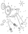
- the valve train 9 includes a timing gear 24 that is integrally rotatably mounted on the crankshaft 2, a camshaft 25 that is rotatably supported on the bottom 19 a of the crankcase main body 19, A pair of lifters 27 that are swingably supported at the bottom 19a of the crankcase body 19 via stepped bolts 26, and are swingably supported at the front end of the cylinder block 21b via a rocker arm shaft 28, and one end thereof.
- a pair of rocker arms 29 abutting on the front end of the intake valve 5 or the exhaust valve 6 and a push rod housing 21 e formed at the lower part of the cylinder unit 21.
- a pair of push rods 30, and the intake valve 5 and the exhaust valve 6 are urged in the valve closing direction.
- the camshaft 25 meshes with the timing gear 24, and a pair of gears 25a that are driven to rotate at a reduction ratio of 1/2 with the timing gear 24, and a pair of lifters 27 that alternately press the pair of lifters 27 in response to the rotation of the gear 25a.
- Cam portions 25b and 25c When the cam portions 25b and 25c push the lifter 27, the other end of the corresponding rocker arm 29 is pushed via the push rod 30, and the intake valve 5 or the exhaust valve 6 connected to one end of the rocker arm 29 opens. When the lift of the lifter 27 by the cam portion 25b is released, the intake valve 5 or the exhaust valve 6 is closed by the urging force of the valve spring 31.
- the cam portion 25b functions as an intake valve operating cam for opening and closing the intake valve 5
- the cam portion 25c functions as an exhaust valve operating cam for opening and closing the exhaust valve 6.
- the camshaft 25 of this embodiment is disposed below the cylinder base 21a of the cylinder unit 21. By disposing the camshaft 25 in this manner, the inside of the crankcase main body 19 can be accessed from above without removing the camshaft 25 by simply removing the crankcase cover 20 during maintenance of the engine E.
- the camshaft 25 has a circular concave portion 25d on the upper surface, and the decompression device 50 is incorporated in the concave portion 25d.
- the decompression device 50 of the present embodiment is provided on the decompression weight 51 that is rotatably disposed via a pivot 25 e provided on the camshaft 25, a decompression spring 52 that biases the decompression weight 51, and the decompression weight 51.
- a decompression shaft 56, a decompression weight 51, a decompression spring 52, and a hold plate 57 that covers the recess 25d while holding the decompression shaft 56 are provided.
- the decompression device 50 When the engine E is started, the decompression device 50 is located at the advanced position where the decompression cam 54 projects from the cam surface of the cam portion 25b or the cam portion 25c. On the other hand, after the engine E is started, the decompression cam 51 is retracted from the cam surface of the cam portion 25b or the cam portion 25c as the decompression weight 51 rotates against the urging force of the decompression spring 52 due to centrifugal force. The decompression shaft 56 rotates so as to move to the retracted position where the decompression lift for the intake valve 5 or the exhaust valve 6 is released.
- the concave portion 25d of the camshaft 25, the decompression weight 51, the decompression spring 52, and the decompression shaft 56 will be described in detail.
- the concave portion 25d of the camshaft 25 supports the decompression shaft 56 rotatably in addition to the pivot 25e described above, and a decompression shaft support hole for exposing the decompression cam 54 to the cam surface of the cam portion 25b or the cam portion 25c so as to advance and retreat.
- the decompression weight 51 is a metal plate member having an arc shape along the inner peripheral wall portion 25h of the camshaft 25.
- the decompression weight 51 includes a fitting hole 51b rotatably fitted to the pivot 25e of the camshaft 25, and a decompression release.
- the outer peripheral portion 51c sometimes abutting on the inner peripheral wall portion 25h of the camshaft 25, the inner peripheral portion 51d facing the outer peripheral portion 51c, the guide groove 51a engaging with the engagement pin 53 of the decompression shaft 56, and the guide groove 51a.
- a rotation regulating groove 51e provided continuously and provided at a connection portion between the guide groove 51a and the inner peripheral portion 51d.
- the decompression spring 52 is a torsion coil spring, and is disposed on the pivot 25 e of the camshaft 25.
- the decompression spring 52 urges the decompression weight 51 inward by engaging one end with the camshaft 25 and engaging the other end with the decompression weight 51.
- the decompression weight 51 thus configured includes a rotation position (hereinafter, appropriately referred to as a decompression operation position) in which the rotation regulating groove 51e contacts the engagement pin 53, and an outer peripheral portion 51c having an inner peripheral wall portion of the camshaft 25. It is rotatable between a rotation position (hereinafter, appropriately referred to as a decompression release position) abutting on 25h, and when the engine E is started, the decompression operation position is maintained by the urging force of the decompression spring 52. After the start of the engine E, the engine E rotates to the decompression release position against the urging force of the decompression spring 52 due to the centrifugal force.
- a rotation position hereinafter, appropriately referred to as a decompression operation position
- a decompression release position abutting on 25h
- the guide groove 51 a is provided on the distal end side of the decompression weight 51 that is separated from the rotation fulcrum (the pivot 25 e), and engages with the engagement pin 53 of the decompression shaft 56 to rotate the decompression weight 51. Is linked. More specifically, the guide groove 51a rotates the decompression shaft 56 to a rotation position where the decompression cam 54 projects from the cam surface of the cam portion 25b or the cam portion 25c when the decompression weight 51 is located at the decompression operation position. When the decompression weight 51 is at the decompression release position, the decompression shaft 56 is rotated to a rotation position at which the decompression cam 54 is retracted from the cam surface of the cam portion 25b or the cam portion 25c.
- the rotation restricting groove 51e restricts the rotation of the decompression shaft 56 when a force is applied from the lifter 27 to the decompression cam 54 in the direction in which the decompression cam 54 moves from the advanced position to the retracted position (when the engine E is rotated in reverse, which will be described later).
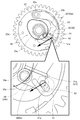
- the rotation restricting groove 51e has a restricting surface 51f orthogonal to an imaginary line L (see FIG. 10D) connecting the pivot 25e and the engaging pin 53 when the decompression cam 54 is at the advanced position.
- the decompression shaft 56 rotates between the decompression operation position and the decompression release position in conjunction with the rotation of the decompression weight 51.
- the decompression cam 54 provided on the decompression shaft 56 has a circumferential surface 54a and a flat surface 54b in which a part of the circumferential surface 54a is cut.
- the circumferential surface 54a of the decompression cam 54 is projected from the cam surface of the cam portion 25b or the cam portion 25c, while when the decompression shaft 56 is located at the decompression release position.
- FIGS. 10A to 10D the cam portions 25b and 25c are indicated by solid lines, but the cam portions 25b and 25c are located on the opposite side of the recess 25d.
- the decompression cam 54 provided on the decompression shaft 56 is located at the advanced position protruding from the cam surface of the cam portion 25b or the cam portion 25c, and the decompression lift is given to the intake valve 5 or the exhaust valve 6 by In addition, the startability of the engine E is improved.
- the decompression weight 51 rotates toward the decompression release position against the urging force of the decompression spring 52 due to the centrifugal force.
- the engagement pin 53 of the decompression shaft 56 is located in the guide groove 51a of the decompression weight 51, and is pushed by the decompression weight 51 in the direction of the arrow in FIG. Rotate.
- the decompression cam 54 provided on the decompression shaft 56 moves to the retracted position retracted from the cam surface of the cam portion 25b or the cam portion 25c, so that the intake valve 5 or the exhaust valve 6 is released.
- the piston 4 may not be able to cross the compression top dead center, and reverse rotation may occur.
- a force acts on the decompression cam 54 from the lifter 27 in a direction to move the decompression cam 54 from the advanced position to the retracted position. This force tries to rotate the decompression shaft 56 in the decompression releasing direction, but when the engagement pin 53 of the decompression shaft 56 moves from the position of FIG. 10A to the position of FIG. It contacts only the regulation surface 51f of the rotation regulation groove 51e of the decompression weight 51.
- the rotation regulating groove 51e has the regulating surface 51f orthogonal to the imaginary line L connecting the pivot 25e and the engaging pin 53 when the decompression cam 54 is in the advanced position in the decompression operation state.
- the engagement pin 53 comes into contact with the regulating surface 51f.
- the force acts only in the direction of the arrow in FIG. 10D. Therefore, the vector for rotating the decompression weight 51 does not act on the decompression weight 51, and the rotation of the decompression shaft 56 is restricted. Therefore, decompression release due to reverse rotation when the engine E is stopped is prevented.
- the decompression device of the small general-purpose engine mounted on a walking lawn mower and the like is illustrated.
- the decompression device of the present invention is not limited to the small general-purpose engine, and may be applied to various engines. Can be.
- a camshaft having an intake valve operating cam (cam portion 25c) and an exhaust valve operating cam (cam portion 25b);
- a decompression weight (decompression weight 51) rotatably disposed via a pivot (a pivot 25e) provided on the camshaft;
- a decompression spring decompression spring 52 for urging the decompression weight;
- An engaging pin engaging pin 53 guided by a guide groove (guide groove 51a) provided on the decompression weight, and can be advanced and retracted to one of the cam surfaces of the intake valve cam and the exhaust valve cam.
- a decompression shaft including a decompression cam (decompression cam 54) provided on the front side and a connection portion (connection portion 55) connecting the engagement pin and the decompression cam
- the decompression weight has a rotation restriction groove (rotation restriction) for restricting rotation of the decompression shaft when a force acts on the decompression shaft in a direction in which the decompression cam moves from the advanced position to the retreat position when the engine is stopped.
- a decompression device for an engine wherein a groove 51e) is provided continuously with the guide groove.
- the decompression device for an engine according to (1),
- the rotation regulating groove has a regulating surface (regulating surface 51f) orthogonal to a virtual line (virtual line L) connecting the pivot and the engaging pin when the decompression cam is at the advanced position.
- An engine decompression device for an engine wherein, when a force acts on the decompression shaft in a direction in which the decompression cam moves from the advanced position to the retreat position, the engagement pin abuts on the restriction surface.
- valve mechanism 9) that operates an intake valve (intake valve 5) and an exhaust valve (exhaust valve 6) according to rotation of a crankshaft (crankshaft 2); (1) or the decompression device according to (2), an engine (engine E), The valve train, A timing gear (timing gear 24) fixed to the crankshaft; The camshaft that rotates in conjunction with the rotation of the timing gear; A pair of lifters (lifters 27) contacting the intake valve cam and the exhaust valve cam; A pair of rocker arms (rocker arms 29), one end of which contacts the intake valve or the exhaust valve; A pair of push rods (push rods 30) for connecting the pair of lifters to the other ends of the pair of rocker arms; An engine, comprising: a pair of valve springs (valve springs 31) for urging the intake valve and the exhaust valve in a valve closing direction.
Landscapes
- Engineering & Computer Science (AREA)
- Mechanical Engineering (AREA)
- General Engineering & Computer Science (AREA)
- Chemical & Material Sciences (AREA)
- Combustion & Propulsion (AREA)
- Valve Device For Special Equipments (AREA)
Abstract
Description
吸気用動弁カム及び排気用動弁カムを有するカムシャフトと、
該カムシャフトに設けられる枢軸を介して回動可能に配置されるデコンプウェイトと、
前記デコンプウェイトを付勢するデコンプスプリングと、
前記デコンプウェイトに設けられたガイド溝に案内される係合ピンと、前記吸気用動弁カム及び前記排気用動弁カムの一方のカム面に進退可能に設けられるデコンプカムと、該係合ピンと該デコンプカムを連結する連結部と、を備えるデコンプシャフトと、を備え、
遠心力によって前記デコンプウェイトが前記デコンプスプリングの付勢力に抗して回動したとき、前記デコンプカムが前記カム面から突出する進出位置から前記デコンプカムが前記カム面から退避する退避位置に移動するように前記デコンプシャフトが回転する、エンジンのデコンプ装置であって、
前記デコンプウェイトには、前記エンジンの停止時に前記デコンプシャフトに前記デコンプカムが前記進出位置から前記退避位置に移動する方向に力が作用したときに前記デコンプシャフトの回転を規制する回転規制溝が、前記ガイド溝に連続して設けられている。
クランクシャフトの回転に応じて吸気バルブ及び排気バルブを動作させる動弁機構と、
前記デコンプ装置と、を備えるエンジンであって、
前記動弁機構は、
前記クランクシャフトに固着されるタイミングギヤと、
該タイミングギヤの回転に連動して回転する前記カムシャフトと、
前記吸気用動弁カム及び前記排気用動弁カムと当接する一対のリフタと、
一端部が前記吸気バルブ又は前記排気バルブに当接する一対のロッカアームと、
該一対のロッカアームの他端部に前記一対のリフタを連結させる一対のプッシュロッドと、
前記吸気バルブ及び前記排気バルブをそれぞれ閉弁方向に付勢する一対のバルブスプリングと、を備える。
図4に示すように、エンジン本体1は、クランクケース本体19と、クランクケースカバー20と、シリンダユニット21と、を備える。
図6~図8に示すように、動弁機構9は、クランクシャフト2に一体回転可能に組み付けられるタイミングギヤ24と、クランクケース本体19の底部19aに回転可能に支持されるカムシャフト25と、クランクケース本体19の底部19aに段付ボルト26を介して揺動可能に支持される一対のリフタ27と、シリンダブロック21bの前端部にロッカアームシャフト28を介して揺動可能に支持され、一端部が吸気バルブ5又は排気バルブ6の前端部に当接する一対のロッカアーム29と、シリンダユニット21の下部に形成されるプッシュロッド収容部21eに収容され、一対のロッカアーム29の他端部にそれぞれリフタ27を連結させる一対のプッシュロッド30と、吸気バルブ5及び排気バルブ6をそれぞれ閉弁方向に付勢する一対のバルブスプリング31と、を備える。
つぎに、カムシャフト25に組み込まれるデコンプ装置50について、図9、図10A~図10Dを参照して説明する。
つぎに、エンジンEの始動及び停止に伴うデコンプ装置50の動作について、図10A~図10Dを参照して説明する。なお、図10A~図10Dでは、カム部25b、25cを実線で示しているが、カム部25b、25cは凹部25dの反対側に位置している。
該カムシャフトに設けられる枢軸(枢軸25e)を介して回動可能に配置されるデコンプウェイト(デコンプウェイト51)と、
前記デコンプウェイトを付勢するデコンプスプリング(デコンプスプリング52)と、
前記デコンプウェイトに設けられたガイド溝(ガイド溝51a)に案内される係合ピン(係合ピン53)と、前記吸気用動弁カム及び前記排気用動弁カムの一方のカム面に進退可能に設けられるデコンプカム(デコンプカム54)と、該係合ピンと該デコンプカムを連結する連結部(連結部55)と、を備えるデコンプシャフト(デコンプシャフト56)と、を備え、
遠心力によって前記デコンプウェイトが前記デコンプスプリングの付勢力に抗して回動したとき、前記デコンプカムが前記カム面から突出する進出位置から前記デコンプカムが前記カム面から退避する退避位置に移動するように前記デコンプシャフトが回転する、エンジン(エンジンE)のデコンプ装置(デコンプ装置50)であって、
前記デコンプウェイトには、前記エンジンの停止時に前記デコンプシャフトに前記デコンプカムが前記進出位置から前記退避位置に移動する方向に力が作用したときに前記デコンプシャフトの回転を規制する回転規制溝(回転規制溝51e)が、前記ガイド溝に連続して設けられている、エンジンのデコンプ装置。
前記回転規制溝は、前記デコンプカムが前記進出位置にあるときに、前記枢軸と前記係合ピンとを結ぶ仮想線(仮想線L)に直交する規制面(規制面51f)を有し、
前記デコンプシャフトに前記デコンプカムが前記進出位置から前記退避位置に移動する方向に力が作用したときに、前記係合ピンが前記規制面と当接する、エンジンのデコンプ装置。
(1)又は(2)に記載の前記デコンプ装置と、を備えるエンジン(エンジンE)であって、
前記動弁機構は、
前記クランクシャフトに固着されるタイミングギヤ(タイミングギヤ24)と、
該タイミングギヤの回転に連動して回転する前記カムシャフトと、
前記吸気用動弁カム及び前記排気用動弁カムと当接する一対のリフタ(リフタ27)と、
一端部が前記吸気バルブ又は前記排気バルブに当接する一対のロッカアーム(ロッカアーム29)と、
該一対のロッカアームの他端部に前記一対のリフタを連結させる一対のプッシュロッド(プッシュロッド30)と、
前記吸気バルブ及び前記排気バルブをそれぞれ閉弁方向に付勢する一対のバルブスプリング(バルブスプリング31)と、を備える、エンジン。
2 クランクシャフト
5 吸気バルブ
6 排気バルブ
9 動弁機構
24 タイミングギヤ
25 カムシャフト
25b カム部(吸気用動弁カム)
25c カム部(排気用動弁カム)
25e 枢軸
27 リフタ
29 ロッカアーム
30 プッシュロッド
31 バルブスプリング
50 デコンプ装置
51 デコンプウェイト
51a ガイド溝
51e 回転規制溝
51f 規制面
52 デコンプスプリング
53 係合ピン
54 デコンプカム
55 連結部
56 デコンプシャフト
L 仮想線
Claims (3)
- 吸気用動弁カム及び排気用動弁カムを有するカムシャフトと、
該カムシャフトに設けられる枢軸を介して回動可能に配置されるデコンプウェイトと、
前記デコンプウェイトを付勢するデコンプスプリングと、
前記デコンプウェイトに設けられたガイド溝に案内される係合ピンと、前記吸気用動弁カム及び前記排気用動弁カムの一方のカム面に進退可能に設けられるデコンプカムと、該係合ピンと該デコンプカムを連結する連結部と、を備えるデコンプシャフトと、を備え、
遠心力によって前記デコンプウェイトが前記デコンプスプリングの付勢力に抗して回動したとき、前記デコンプカムが前記カム面から突出する進出位置から前記デコンプカムが前記カム面から退避する退避位置に移動するように前記デコンプシャフトが回転する、エンジンのデコンプ装置であって、
前記デコンプウェイトには、前記エンジンの停止時に前記デコンプシャフトに前記デコンプカムが前記進出位置から前記退避位置に移動する方向に力が作用したときに前記デコンプシャフトの回転を規制する回転規制溝が、前記ガイド溝に連続して設けられている、エンジンのデコンプ装置。 - 請求項1に記載のエンジンのデコンプ装置であって、
前記回転規制溝は、前記デコンプカムが前記進出位置にあるときに、前記枢軸と前記係合ピンとを結ぶ仮想線に直交する規制面を有し、
前記デコンプシャフトに前記デコンプカムが前記進出位置から前記退避位置に移動する方向に力が作用したときに、前記係合ピンが前記規制面と当接する、エンジンのデコンプ装置。 - クランクシャフトの回転に応じて吸気バルブ及び排気バルブを動作させる動弁機構と、
請求項1又は2に記載の前記デコンプ装置と、を備えるエンジンであって、
前記動弁機構は、
前記クランクシャフトに固着されるタイミングギヤと、
該タイミングギヤの回転に連動して回転する前記カムシャフトと、
前記吸気用動弁カム及び前記排気用動弁カムと当接する一対のリフタと、
一端部が前記吸気バルブ又は前記排気バルブに当接する一対のロッカアームと、
該一対のロッカアームの他端部に前記一対のリフタを連結させる一対のプッシュロッドと、
前記吸気バルブ及び前記排気バルブをそれぞれ閉弁方向に付勢する一対のバルブスプリングと、を備える、エンジン。
Priority Applications (6)
| Application Number | Priority Date | Filing Date | Title |
|---|---|---|---|
| EP18925541.7A EP3800333B1 (en) | 2018-07-05 | 2018-07-05 | Engine decompression device and engine |
| AU2018431113A AU2018431113A1 (en) | 2018-07-05 | 2018-07-05 | Engine decompression device and engine |
| US17/253,399 US11384725B2 (en) | 2018-07-05 | 2018-07-05 | Engine decompression device and engine |
| PCT/JP2018/025600 WO2020008611A1 (ja) | 2018-07-05 | 2018-07-05 | エンジンのデコンプ装置及びエンジン |
| CN201880095354.5A CN112384683B (zh) | 2018-07-05 | 2018-07-05 | 发动机的减压装置及发动机 |
| AU2022246466A AU2022246466B2 (en) | 2018-07-05 | 2022-10-07 | Engine decompression device and engine |
Applications Claiming Priority (1)
| Application Number | Priority Date | Filing Date | Title |
|---|---|---|---|
| PCT/JP2018/025600 WO2020008611A1 (ja) | 2018-07-05 | 2018-07-05 | エンジンのデコンプ装置及びエンジン |
Publications (1)
| Publication Number | Publication Date |
|---|---|
| WO2020008611A1 true WO2020008611A1 (ja) | 2020-01-09 |
Family
ID=69059508
Family Applications (1)
| Application Number | Title | Priority Date | Filing Date |
|---|---|---|---|
| PCT/JP2018/025600 Ceased WO2020008611A1 (ja) | 2018-07-05 | 2018-07-05 | エンジンのデコンプ装置及びエンジン |
Country Status (5)
| Country | Link |
|---|---|
| US (1) | US11384725B2 (ja) |
| EP (1) | EP3800333B1 (ja) |
| CN (1) | CN112384683B (ja) |
| AU (2) | AU2018431113A1 (ja) |
| WO (1) | WO2020008611A1 (ja) |
Citations (2)
| Publication number | Priority date | Publication date | Assignee | Title |
|---|---|---|---|---|
| JPH08177437A (ja) | 1994-12-28 | 1996-07-09 | Honda Motor Co Ltd | エンジンにおけるデコンプ装置 |
| JP2016145537A (ja) * | 2015-02-06 | 2016-08-12 | 富士重工業株式会社 | デコンプ装置 |
Family Cites Families (38)
| Publication number | Priority date | Publication date | Assignee | Title |
|---|---|---|---|---|
| JPS6032507U (ja) | 1983-08-10 | 1985-03-05 | 川崎重工業株式会社 | エンジンのオ−トデコンプ装置 |
| JPH066888B2 (ja) | 1984-07-10 | 1994-01-26 | 富士重工業株式会社 | エンジンのデコンプ装置 |
| US4723516A (en) * | 1985-11-25 | 1988-02-09 | Slagley Michael W | Valve open duration and timing controller |
| JPH0658047B2 (ja) * | 1988-06-14 | 1994-08-03 | 本田技研工業株式会社 | 内燃機関の動弁制御装置 |
| JPH0299706A (ja) * | 1988-10-07 | 1990-04-11 | Fuji Heavy Ind Ltd | エンジンの逆転防止装置 |
| US4898133A (en) | 1988-12-07 | 1990-02-06 | Kohler Co. | Automatic compression release apparatus for an internal combustion engine |
| JPH11229839A (ja) * | 1998-02-09 | 1999-08-24 | Fuji Heavy Ind Ltd | エンジン用デコンプ装置 |
| US6055952A (en) * | 1998-06-08 | 2000-05-02 | Industrial Technology Research Institute | Automatic decompression device |
| JP2001090516A (ja) * | 1999-09-21 | 2001-04-03 | Kubota Corp | デコンプ装置付きエンジン |
| US6394054B1 (en) * | 2001-01-15 | 2002-05-28 | Tecumseh Products Company | Mechanical compression and vacuum release |
| JP4073714B2 (ja) * | 2002-06-10 | 2008-04-09 | 本田技研工業株式会社 | エンジンのオートデコンプ装置 |
| US20040003791A1 (en) | 2002-07-08 | 2004-01-08 | Giuseppe Ghelfi | Compression release mechanism |
| JP2006002741A (ja) * | 2004-06-21 | 2006-01-05 | Suzuki Motor Corp | 船外機用の2気筒v型ohvエンジン |
| JP4234653B2 (ja) * | 2004-09-03 | 2009-03-04 | ヤマハ発動機株式会社 | エンジンのデコンプ装置 |
| US20060065224A1 (en) * | 2004-09-27 | 2006-03-30 | Walbro Engine Management, L.L.C. | Combustion engine pull-cord start system |
| JP4490846B2 (ja) * | 2005-02-21 | 2010-06-30 | 本田技研工業株式会社 | エンジンのデコンプ装置 |
| US7552706B2 (en) * | 2005-04-08 | 2009-06-30 | Mtd Products Inc | Automatic decompression mechanism for an engine |
| JP4549321B2 (ja) * | 2006-07-14 | 2010-09-22 | 本田技研工業株式会社 | 内燃機関のデコンプ装置 |
| JP4896817B2 (ja) * | 2006-07-25 | 2012-03-14 | 本田技研工業株式会社 | 内燃機関の可変動弁装置 |
| JP4887200B2 (ja) * | 2006-08-08 | 2012-02-29 | 本田技研工業株式会社 | デコンプ装置を備えたエンジン |
| JP4540655B2 (ja) * | 2006-11-24 | 2010-09-08 | 本田技研工業株式会社 | デコンプ装置を備える内燃機関 |
| JP2008190424A (ja) * | 2007-02-05 | 2008-08-21 | Honda Motor Co Ltd | 内燃機関のデコンプ装置 |
| JP2009281159A (ja) * | 2008-05-19 | 2009-12-03 | Honda Motor Co Ltd | 内燃機関の排気浄化装置 |
| JP5027739B2 (ja) * | 2008-06-10 | 2012-09-19 | 川崎重工業株式会社 | デコンプ機構 |
| EP2479389B1 (en) * | 2009-09-14 | 2014-07-23 | Honda Motor Co., Ltd. | Valve gear of internal combustion engine |
| TWI393818B (zh) * | 2009-09-14 | 2013-04-21 | Honda Motor Co Ltd | 內燃機引擎的閥驅動裝置 |
| JP5905665B2 (ja) * | 2011-02-08 | 2016-04-20 | 本田技研工業株式会社 | ロッカーアーム装置 |
| CN202659296U (zh) * | 2012-04-05 | 2013-01-09 | 重庆路沃发动机有限公司 | 发动机的减压装置 |
| CN202832685U (zh) * | 2012-10-17 | 2013-03-27 | 四川银钢一通凸轮轴股份有限公司 | 发动机及其凸轮轴 |
| JP6226787B2 (ja) * | 2014-03-19 | 2017-11-08 | 本田技研工業株式会社 | デコンプ機構付き内燃機関 |
| JP2015224578A (ja) * | 2014-05-27 | 2015-12-14 | ヤマハ発動機株式会社 | エンジン及び車両 |
| JP6386290B2 (ja) * | 2014-08-13 | 2018-09-05 | 株式会社工進 | エンジンのデコンプ装置 |
| JP6219537B2 (ja) * | 2014-09-30 | 2017-10-25 | 本田技研工業株式会社 | 内燃機関のデコンプ機構 |
| JP6068424B2 (ja) * | 2014-12-08 | 2017-01-25 | 富士重工業株式会社 | デコンプ装置 |
| JP6653198B2 (ja) * | 2016-03-22 | 2020-02-26 | 本田技研工業株式会社 | 内燃機関 |
| JP6740757B2 (ja) * | 2016-07-05 | 2020-08-19 | スズキ株式会社 | デコンプレッション機構、エンジン及び自動二輪車 |
| JP6702038B2 (ja) | 2016-07-05 | 2020-05-27 | スズキ株式会社 | 可変動弁機構、エンジン及び自動二輪車 |
| CN207131456U (zh) * | 2017-08-18 | 2018-03-23 | 重庆凯驰汽车部件制造有限公司 | 一种通用汽油机减压凸轮轴 |
-
2018
- 2018-07-05 CN CN201880095354.5A patent/CN112384683B/zh not_active Expired - Fee Related
- 2018-07-05 AU AU2018431113A patent/AU2018431113A1/en not_active Abandoned
- 2018-07-05 WO PCT/JP2018/025600 patent/WO2020008611A1/ja not_active Ceased
- 2018-07-05 EP EP18925541.7A patent/EP3800333B1/en active Active
- 2018-07-05 US US17/253,399 patent/US11384725B2/en active Active
-
2022
- 2022-10-07 AU AU2022246466A patent/AU2022246466B2/en not_active Expired - Fee Related
Patent Citations (2)
| Publication number | Priority date | Publication date | Assignee | Title |
|---|---|---|---|---|
| JPH08177437A (ja) | 1994-12-28 | 1996-07-09 | Honda Motor Co Ltd | エンジンにおけるデコンプ装置 |
| JP2016145537A (ja) * | 2015-02-06 | 2016-08-12 | 富士重工業株式会社 | デコンプ装置 |
Non-Patent Citations (1)
| Title |
|---|
| See also references of EP3800333A4 |
Also Published As
| Publication number | Publication date |
|---|---|
| EP3800333B1 (en) | 2024-04-17 |
| US20210262370A1 (en) | 2021-08-26 |
| AU2022246466B2 (en) | 2024-04-11 |
| AU2018431113A1 (en) | 2021-01-21 |
| AU2022246466A1 (en) | 2022-11-03 |
| CN112384683B (zh) | 2022-08-02 |
| EP3800333A1 (en) | 2021-04-07 |
| EP3800333A4 (en) | 2021-06-09 |
| CN112384683A (zh) | 2021-02-19 |
| US11384725B2 (en) | 2022-07-12 |
Similar Documents
| Publication | Publication Date | Title |
|---|---|---|
| JP4057976B2 (ja) | 圧縮比可変エンジン | |
| JP4490846B2 (ja) | エンジンのデコンプ装置 | |
| WO2011030456A1 (ja) | 内燃機関の動弁装置 | |
| EP1985812B1 (en) | V-type engine | |
| JP4172186B2 (ja) | エンジンのデコンプ装置 | |
| JP7085618B2 (ja) | エンジン | |
| CA2636613C (en) | Mechanical compression and vacuum release mechanism | |
| AU2022246466B2 (en) | Engine decompression device and engine | |
| JP2005233176A (ja) | デコンプ装置及びそれを有する4サイクルエンジン | |
| US11073078B2 (en) | Engine | |
| JP2003278567A (ja) | 圧縮比可変エンジン | |
| JP7059356B2 (ja) | エンジン | |
| JP2009264251A (ja) | 内燃機関の動弁装置 | |
| JP4454872B2 (ja) | 内燃機関のデコンプ装置 | |
| JP2002115518A (ja) | エンジンのデコンプ構造 | |
| JP5456612B2 (ja) | 内燃機関のデコンプ装置 | |
| JP4116860B2 (ja) | 圧縮比可変エンジン | |
| JP7047067B2 (ja) | エンジン | |
| JPH11107727A (ja) | 内燃機関始動時減圧装置 | |
| US20210010444A1 (en) | Engine | |
| WO2019187094A1 (ja) | エンジン |
Legal Events
| Date | Code | Title | Description |
|---|---|---|---|
| 121 | Ep: the epo has been informed by wipo that ep was designated in this application |
Ref document number: 18925541 Country of ref document: EP Kind code of ref document: A1 |
|
| NENP | Non-entry into the national phase |
Ref country code: DE |
|
| ENP | Entry into the national phase |
Ref document number: 2018925541 Country of ref document: EP Effective date: 20210104 |
|
| ENP | Entry into the national phase |
Ref document number: 2018431113 Country of ref document: AU Date of ref document: 20180705 Kind code of ref document: A |
|
| NENP | Non-entry into the national phase |
Ref country code: JP |