WO2020008657A1 - Machine de liaison - Google Patents
Machine de liaison Download PDFInfo
- Publication number
- WO2020008657A1 WO2020008657A1 PCT/JP2018/033115 JP2018033115W WO2020008657A1 WO 2020008657 A1 WO2020008657 A1 WO 2020008657A1 JP 2018033115 W JP2018033115 W JP 2018033115W WO 2020008657 A1 WO2020008657 A1 WO 2020008657A1
- Authority
- WO
- WIPO (PCT)
- Prior art keywords
- binding
- binding material
- movable member
- winding
- movement
- Prior art date
- Legal status (The legal status is an assumption and is not a legal conclusion. Google has not performed a legal analysis and makes no representation as to the accuracy of the status listed.)
- Ceased
Links
Images



Classifications
-
- B—PERFORMING OPERATIONS; TRANSPORTING
- B65—CONVEYING; PACKING; STORING; HANDLING THIN OR FILAMENTARY MATERIAL
- B65B—MACHINES, APPARATUS OR DEVICES FOR, OR METHODS OF, PACKAGING ARTICLES OR MATERIALS; UNPACKING
- B65B13/00—Bundling articles
- B65B13/02—Applying and securing binding material around articles or groups of articles, e.g. using strings, wires, strips, bands or tapes
- B65B13/04—Applying and securing binding material around articles or groups of articles, e.g. using strings, wires, strips, bands or tapes with means for guiding the binding material around the articles prior to severing from supply
- B65B13/08—Single guide or carrier for the free end of material movable part-away around articles from one side only
-
- B—PERFORMING OPERATIONS; TRANSPORTING
- B65—CONVEYING; PACKING; STORING; HANDLING THIN OR FILAMENTARY MATERIAL
- B65B—MACHINES, APPARATUS OR DEVICES FOR, OR METHODS OF, PACKAGING ARTICLES OR MATERIALS; UNPACKING
- B65B13/00—Bundling articles
- B65B13/18—Details of, or auxiliary devices used in, bundling machines or bundling tools
- B65B13/24—Securing ends of binding material
- B65B13/28—Securing ends of binding material by twisting
-
- B—PERFORMING OPERATIONS; TRANSPORTING
- B65—CONVEYING; PACKING; STORING; HANDLING THIN OR FILAMENTARY MATERIAL
- B65B—MACHINES, APPARATUS OR DEVICES FOR, OR METHODS OF, PACKAGING ARTICLES OR MATERIALS; UNPACKING
- B65B13/00—Bundling articles
- B65B13/02—Applying and securing binding material around articles or groups of articles, e.g. using strings, wires, strips, bands or tapes
- B65B13/04—Applying and securing binding material around articles or groups of articles, e.g. using strings, wires, strips, bands or tapes with means for guiding the binding material around the articles prior to severing from supply
- B65B13/06—Stationary ducts or channels
Definitions
- the present invention relates to a binding machine that binds a binding object by winding a binding material around the binding object and twisting the binding material.
- a binding machine of a type in which a binding material is wound around a binding object and twisted to bind the binding object For example, a binding machine is used to bind a bag mouth or the like with a string-shaped binding material.
- Patent Document 1 describes a binding machine that winds and twists a binding material around an article.
- the bundling machine includes a delivery device for delivering a bundling material for bundling articles, a bending / wrapping device for winding the delivered bundling material around the product, and further winding and tightening and fixing the folded and wound bundling material to the product.
- a replenishing drum for supplying a binding material is provided at the rear end of the casing body.
- the delivery device by rotating the delivery disk in a predetermined direction, the delivery device, the insertion port clamping device, the cutting device, and the twisting device are operated, and the connecting rod and the linkage provided on the delivery disk are operated.
- the bending and winding device and the clamp device are operated by connecting the rod drive shaft so as to be rotatable and laterally movable and rotating the delivery disk in a predetermined direction.
- a motor in order to drive various devices with one motor, a motor is provided for the sending-out disc, and for other devices requiring power, the power of the motor is connected via a connecting rod. Is transmitted.
- the folding and wrapping device is remote from the motor. Therefore, in order to transmit the power of the motor to the folding and winding device, parts such as a long connecting rod, a connecting rod driving shaft and a clamp driving shaft connected to the connecting rod are required, and the mechanical configuration is reduced. It was complicated and it was difficult to reduce the manufacturing cost.
- the present invention has been made in view of such circumstances, and it is possible to simplify a mechanical configuration in a binding machine that binds a binding object by winding a binding material around the binding object and twisting the binding material. It is an object to provide a simple binding machine.
- a first invention is a binding machine that binds a binding material by winding the binding material around the binding material and twisting the binding material.
- the elastically deforming portion returns the movable member to the pre-movement position by the restoring force and returns the winding member to the pre-rotation position before rotating to wind the binding material.
- the movable member includes a traversing portion that traverses the moving passage, a first slide supporting portion connected to one side of the moving passage in the traversing portion and slidably supported, A second slide supporting portion connected to the other side of the moving passage in the portion and slidably supported, wherein the elastically deforming portion applies a restoring force to return the movable member to the pre-movement position on the first slide supporting portion.
- the movable member is slidably provided along the movement path, and the rotation center of the winding member is set when the movable member is at the pre-movement position. And the distance from the point of action to the point at which the force transmitted from the movable member acts on the winding member is 0.5 cm or more and 3 cm or less.
- the switch that switches to the ON state by contacting the movable member or the wrapping member at the timing when the binding object reaches the binding execution position, and the switch is turned ON.
- the state is switched, power is supplied, and a motor for driving the twisting device is provided.
- a switch that switches to an ON state by contacting the movable member or the winding member at a timing when the movable member returns to the pre-movement position; When the switching is performed, power is supplied, and a motor that drives the delivery device is provided.
- the apparatus further comprises a binding material passage for guiding the binding material inserted from the outside to a predetermined position, and the binding material delivered by the delivery device is provided.
- the apparatus is configured to advance along the moving path from the outlet of the binding material path to a predetermined position in an area adjacent to the moving path.
- the torsion device comprises: a torsion shaft rotatably provided; the torsion device fixed to the torsion shaft and wound around the object to be bound when the torsion shaft rotates.
- a hook that rotates in a state where the binding material is hooked, and the power of the movable member moved from the pre-movement position is transmitted and moved, so that the binding material is twisted by the twisting device toward the torsion shaft side.
- the movable member is moved by being pushed by the binding object moving toward the binding execution position, and furthermore, the power of the movable member is transmitted, and the binding member is wound around the binding object by the rotating winding member. Can be hung. That is, the binding material is wound around the binding object using the force for moving the binding object to the binding execution position. Therefore, unlike the conventional binding machine, it is not necessary to transmit the power of the motor to the wrapping member, and the components that complicate the mechanical configuration in the conventional binding machine can be omitted.
- the binding machine which can simplify a mechanical structure can be provided in the binding machine which binds a binding object by winding a binding material around a binding object and twisting.
- the preparation for the next binding can be automatically performed after the binding to the binding object is completed. it can.
- the restoring force applied to the first slide support provided with the power transmission unit with respect to the wrapping member is greater than the restoring force applied to the second slide support. Therefore, the balance of the force for returning the movable member to the pre-movement position can be balanced on both sides of the movement passage, and the movable member can be returned stably.
- the distance from the center of rotation of the winding member to the point of action at which the force transmitted from the movable member acts on the winding member (hereinafter referred to as “center-point of action”) is 0. 5 cm or more and 3 cm or less.
- center-point of action In order to wind the binding material, it is necessary to relatively rotate the winding member. To that end, it is conceivable to increase the sliding range of the sliding member. However, when the slide range of the slide member is increased, the distance for pressing the slide member for the user becomes longer. Also, by reducing the distance between the center and the action point, it is possible to largely rotate the winding member. However, in this case, the force required to move the slide member increases.
- the center-action point distance to be 0.5 cm or more and 3 cm or less, the force required to move the slide member while suppressing the slide range is not excessively large. Therefore, it is possible to suppress an increase in the burden on the user pressing the movable member.
- the motor for driving the twisting device is automatically driven by utilizing the movement of the movable member or the wrapping member when moving the binding object to the binding execution position. Therefore, the binding machine can be automated with a simple configuration.
- the motor for driving the delivery device is automatically driven by utilizing the movement of returning the movable member or the wrapping member. Therefore, the binding machine can be automated with a simple configuration.
- the binding material delivered by the delivery device is moved along the movement path from the outlet of the binding material path to a predetermined position where the material can be wound around the material to be bound by the winding member. Proceed to adjacent area. Therefore, it is possible to reliably prevent the movement of the binding object from being hindered by the binding material entering the moving passage.
- the binding material is moved to the twisting shaft side before the binding material is twisted by using the force for moving the binding object to the binding execution position.
- the position of the binding material approaches the rotation center of the hook. Therefore, the binding material can be reliably twisted by the hook portion.
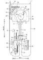
- FIG. 1 is a perspective view of the binding machine according to the present embodiment.
- FIG. 2 is a top view of the inside of the main body viewed from above.
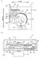
- FIG. 3A is a top view of the inside of the rear side of the main body viewed from above with the switch mounting plate and the switch operation plate removed, and
- FIG. 3B is a rear view of the inside of the main body. It is the rear view seen from. 4A and 4B are diagrams for explaining the slide member.
- FIG. 4A is a top view illustrating a state in which the slide member exists at the pre-movement position.
- FIG. It is a top view of the state which exists in a position.
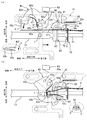
- 5A and 5B are views for explaining a wrapping arm and the like.
- FIG. 5A is a top view in a state where the wrapping arm is at a position before rotation
- FIG. It is a top view in the state where an arm exists in a winding completion position.
- FIG. 6A is a top view of the rotating disk and the switch operation plate before the first switch is pressed and rotated
- FIG. 6B is a rotating disk when the second switch is pressed and stopped.
- FIG. 4 is a top view of a switch operation plate.
- the binding machine 10 is a machine that winds a binding material 2 in the form of a string around the binding object 1 and then twists and binds the binding material 2.
- a binding machine 10 shown in FIG. 1 includes a main body 11 that ties the object 1 to be bound, a main body support 12 that is integrated below the main body 11 and supports the main body 11, And a reel stand 18 attached to the rear side.
- a movement passage (slot) 13 through which the material 1 to be bound is moved to a binding execution position 13a where binding is performed is formed in the main body portion 11 by notch. Details of the main body 11 will be described later.
- the entrance side of the moving passage 13 is referred to as “front side”, and the opposite side is referred to as “rear side”.
- the moving passage 13 extends straight in the front-rear direction. Further, a direction orthogonal to the front-rear direction is referred to as a “width direction”. Further, “right side” or “left side” is used as a direction when the binding machine 10 is viewed from the front side.
- the main body support 12 is covered with the outer case 17 together with the main body 11.
- a power switch is provided on the outer surface of the main body support portion 12, and a power cord is connected thereto. Electrical components are accommodated in the main body support portion 12 (not shown).
- a leg is provided below the main body support 12.
- the winding stand 15 is attached to the reel stand 18.
- the binding material 2 is wound around the winding reel 15.
- a string-like binding material in which a metal or resin core is incorporated in a resin string (eg, a vinyl string) or a paper string can be used.
- the main body unit 11 includes a feeding device 20, a winding device 40, a twisting device 60, and a cutting device 70.
- An insertion port 16 for inserting the binding material 2 unwound from the winding reel 15 is formed on the rear surface of the main body 11.
- a binding material passage 14 for guiding an end of the binding material 2 inserted from the insertion opening 16 to a predetermined position where the binding material 2 can be wound (a predetermined position) is formed inside the main body 11.
- the position where the binding material 2 can be wound is a position where the binding material 2 can be wound around the material 1 to be bound by a winding arm 42 described later.
- the binding material passage 14 extends horizontally forward from the insertion opening 16 in the main body 11, and a hole of a fixed blade 71 described later serves as an outlet 14 a of the binding material passage 14.
- the insertion port 16 is provided at a position on the left side in the width direction, which is closer to the outside.
- the outlet 14a of the binding material passage 14 opens at a position on the left side of the moving passage 13 near the center in the width direction.
- the binding material 2 delivered by the delivery device 20 described below travels along the movement path 13 in an area adjacent to the movement path 13 from the outlet 14a of the binding material path 14 to a position where the binding material can be wound.
- a binding material passage 14 and the like are configured. Specifically, in a top view, the binding material passage 14 bends inward behind a portion sandwiched between a driving roller 23 and a driven roller 24, which will be described later, and extends obliquely to a position slightly behind the outlet 14a. . And it extends substantially forward from a little rear side of the outlet 14a to the outlet 14a. Strictly speaking, the outlet 14a of the binding material passage 14 is slightly outward (left side).
- a rotating arm 91 described later is arranged at the left front of the outlet 14a. Therefore, the binding material 2 sent forward from the outlet 14 a of the binding material passage 14 advances slightly obliquely toward the outside, hits the rotating arm 91, and the traveling direction is corrected forward. Thus, the binding material 2 sent forward from the outlet 14a is prevented from entering the moving passage 13.
- a plurality of support plates to which various components described later are attached are stacked and fixed to each other (see FIG. 3B).
- the support plate portion 30 including the plurality of support plates is fixed to the outer case 17.
- the delivery device 20 is a device that delivers the binding material 2 forward after the binding of the binding object 1 is completed.
- the delivery device 20 includes a motor 21, a rotating disk 22 connected to a rotating shaft 21 a of the motor 21, a driving roller 23 to which rotational force is transmitted from the rotating disk 22, A driven roller 24 that sandwiches the binding material 2 together with the roller 23, a roller elastic member 25 that presses the driven roller 24 against the driving roller 23, and a switch that covers the rotating disk 22 and the like and has a second switch 82 described below provided on the upper surface It has a mounting plate 26 and a switch operation plate 27 mounted on the rotary shaft 21a on the switch mounting plate 26.
- the motor 21 is arranged inside the main body support 12.
- FIG. 3A shows a state in which the switch mounting plate 26 and the switch operation plate 27 have been removed, and the formation region of the rear gear 22c and the torsion gear 63 is hatched.
- FIG. 3B the illustration of the roller elastic member 25 and the like is omitted.
- the axis of the rotating shaft 21a extends in the up-down direction. This is the same for the other rotating shafts 23a, 24a, 28a, 42a, and 91a.
- the rotating disk 22 is a substantially circular plate-like member in plan view. As shown in FIG. 3B, the rotating disk 22 is provided with a front gear 22b and a rear gear 22c.
- the front gear 22b is a gear for rotating the drive roller 23.
- the front gear 22b is, for example, a spur gear, and is provided only in a part of the angle range of the rotating disk 22.
- the back side gear 22c is a gear for rotating a torsion shaft 61 described later.
- the back side gear 22c is, for example, a face gear, and is formed only in a part of the angle range of the rotating disk 22.
- the drive roller 23 is disposed slightly before the insertion port 16.
- the drive roller 23 is rotatably attached to a rotation shaft 23 a fixed to the support plate 30.
- the drive roller 23 is integrated with a roller-side gear 23b that meshes with the front-side gear 22b.
- the roller-side gear 23 b is, for example, a spur gear, and is formed over the entire circumference of the drive roller 23.
- the driven roller 24 is disposed at a position facing the driving roller 23.
- the driven roller 24 is rotatably attached to a rotation shaft 24 a fixed to the support member 28.
- the support member 28 is rotatably supported by a rotation shaft 28 a fixed to the support plate 30.
- the position of the driven roller 24 is determined by a pressing position (the position shown in FIG. 3A) for pressing the driving roller 23 with the rotation of the support member 28 and a separating position separated from the driving roller 23 (the left side of FIG. 3A). Position).
- the driven roller 24 at the pressing position contacts the drive roller 23 on the binding material path 14.
- a lever 29 that extends rearward from the outer case 17 is fixed to the support member 28. Further, one end of a roller elastic member 25 is attached to the lever 29. The other end of the roller elastic member 25 is attached to the hook 26a of the switch attachment plate 26 in a state where the other end is longer than the natural length.
- the support roller 28 is rotated clockwise in FIG. 3A, and the driven roller 24 integrated with the support member 28 is pressed against the drive roller 23 at the pressing position.
- the support member 28 rotates counterclockwise, and the driven roller 24 moves to the separated position.
- the binding material 2 unwound from the winding reel 15 and inserted from the insertion opening 16 can be sandwiched between the driving roller 23 and the driven roller 24.
- a coil spring can be used as the elastic member 25 for the roller.
- the rotating disk 22 rotates. Then, in a part of the rotation angle range in one rotation of the rotating disk 22, the front gear 22b and the roller gear 23b mesh with each other, and the rotational force of the motor 21 is transmitted to the drive roller 23.
- the driving roller 23 rotates with the binding material 2 sandwiched between the driving roller 23 and the driven roller 24, the driven roller 24 also rotates with the rotation, and the binding material 2 is sent forward.
- the switch operation plate 27 When the motor 21 rotates, the switch operation plate 27 also rotates above the switch mounting plate 26 on which the second switch 82 is mounted on the upper surface.
- the switch operation plate 27 is a cam whose distance from the center of the rotating shaft 21a to the outer periphery changes in the circumferential direction.
- a bulging portion 27a bulging outward is formed in a part of the angular range in the circumferential direction. While the switch operation plate 27 is rotating, the second switch 82 is switched by the bulging portion 27a during a period in which the bulging portion 27a faces the second switch 82.
- the wrapping device 40 is a device that automatically wraps the binding material 2 around the tied object 1 using the force of moving the tied object 1 to the binding execution position 13a.
- the winding device 40 includes a slide member 41 provided slidably, a winding arm 42 provided rotatably, a power transmission unit 43 for transmitting power from the slide member 41 to the winding arm 42, and a slide member.
- the slide member 41 includes a slide direction restricting portion 44 for restricting a slide direction of the slide member 41 and a slide return portion 45 for urging the slide member 41 forward by a restoring force.
- the slide member 41 corresponds to a movable member that is moved by being pushed by the binding object 1 that is moving toward the binding execution position 13a from the pre-movement position where at least a part is arranged in the movement passage 13.
- the winding arm 42 is equivalent to a winding member that winds the binding material 2 sent out to a predetermined position by the delivery device 20 around the material 1 to be bound by the rotation of the slide member 41 when the power of the slide member 41 is transmitted.
- the slide return portion 45 corresponds to an elastically deforming portion that returns the slide member 41 to the position before the movement by the restoring force and returns the winding arm 42 to the position before the rotation before rotating for winding the binding material 2.
- the sliding member 41 is connected to one side (left side) of the moving passage 13 in the crossing portion 41a and traverses the moving passage 13 and is slidably supported. It has a slide support portion 41b and a second slide support portion 41c connected to the other side (right side) of the moving passage 13 in the cross section 41a and slidably supported.
- the crossing portion 41 a is formed in a straight long plate shape, and extends substantially perpendicular to the extending direction of the moving passage 13.
- a concave portion 41d into which the binding object 1 enters is formed on the front side of a portion of the crossing portion 41a that straddles the moving passage 13. Thereby, the binding object 1 that pushes the slide member 41 is less likely to shift in the width direction of the moving passage 13.
- the first slide support portion 41b includes an inner portion 41e that extends outward (leftward) from the transverse portion 41a, and a long plate-shaped outer portion 41f that is formed continuously with the inner portion 41e and extends in the front-rear direction. I have.
- An elongated hole 43a constituting the power transmission unit 43 is formed in the inner part 41e.
- a rear outer peripheral portion 92b for pressing a projecting pin 92a described later is formed behind the inner portion 41e.
- two long holes 44a constituting the slide direction regulating portion 44 are formed in the outer portion 41f.
- a protruding portion 41h that contacts a first switch 81 described later is formed at a rear end portion of the outer portion 41f.
- the second slide support portion 41c is a long plate-shaped portion formed continuously outside the transverse portion 41a and extending in the front-rear direction.
- the second slide support portion 41c has one elongated hole 44a constituting the slide direction regulating portion 44.
- a second elastic member 52 constituting the slide return portion 45 is attached to a pin 41i protruding from the upper surface of the second slide support portion 41c.
- the slide direction restricting portion 44 includes the above-described three elongated holes 44a extending in the front-rear direction and the three restriction pins 44b inserted into the three long holes 44a, respectively, and changes the sliding direction of the slide member 41 in the front-rear direction (moving direction). (Extending direction of the passage 13).
- the three long holes 44a have the same length in the front-rear direction.
- the three regulating pins 44b are arranged so that their positions in the front-rear direction with respect to the elongated holes 44a into which the three regulating pins 44b are inserted are the same.
- the sliding range of the slide member 41 is from a pre-movement position before being pushed by the binding object 1 (a position in FIG.
- the slide return portion 45 includes a first elastic member 51 that pulls the first slide support portion 41b forward, and a second elastic member 52 that pulls the second slide support portion 41c forward.
- the first elastic member 51 corresponds to a first spring portion that applies a restoring force for returning the slide member 41 to the pre-movement position to the first slide support portion 41b.
- the second elastic member 52 corresponds to a second spring portion that applies a restoring force for returning the slide member 41 to the position before the movement to the second slide support portion 41c.
- a coil spring is used for each of the elastic members 51 and 52.
- each of the first spring portion and the second spring portion is constituted by one elastic member 51, 52, but may be constituted by a plurality of elastic members.
- first elastic member 51 is attached to a support pin 30a fixed to the support plate portion 30, and the other end is attached to an insertion pin 43b inserted into the elongated hole 43a of the first slide support portion 41b.
- second elastic member 52 has one end attached to a support pin 30b fixed to the support plate 30, and the other end attached to a pin 41i of the second slide support 41c.
- the first elastic member 51 has a larger spring constant between the first elastic member 51 and the second elastic member 52. That is, between the first spring portion and the second spring portion, the first spring portion has a larger restoring force for returning the slide member 41 to the pre-movement position.
- the restoring force applied to the first slide support portion 41b provided with the power transmission portion 43 to the wrapping arm 42 is greater than the restoring force applied to the second slide support portion 41c not provided with the power transmission portion 43. It is larger than the restoring force to be applied. Therefore, the slide member 41 can be returned with good balance on both the left and right sides of the moving passage 13.
- the winding arm 42 is rotatably supported by a rotation shaft 42 a fixed to the support plate 30.
- the winding arm 42 is at the pre-rotation position (the position in FIG. 5A) when the slide member 41 is at the pre-movement position. In this state, the entire winding arm 42 is located on the left side of the moving passage 13. Then, in conjunction with sliding the slide member 41 toward the movement stop position, the winding arm 42 rotates counterclockwise in FIG. 5A, and when the slide member 41 reaches the movement stop position, the winding arm 42 winds.
- the hanging arm 42 reaches the winding completion position (the position shown in FIG. 5B).
- the winding arm 42 includes a plate-shaped arm portion 42b and a binding material holding portion 42c attached to a tip end of the arm portion 42b.
- the winding arm 42 and a donating device 90 to be described later are indicated by solid lines, and a member overlapping the sliding arm 42 and the slide member 41 are indicated by broken lines.
- the arm portion 42b has a planar shape in which a band-like portion extends from a substantially rectangular center portion to which the rotation shaft 42a is attached and is bent in the middle.
- An insertion pin 43b that constitutes the power transmission unit 43 and is inserted into the elongated hole 43a is fixed to the arm 42b in the vicinity of the rotation shaft 42a.
- the belt-like portion extends diagonally forward left and extends diagonally right forward from the bent portion.
- a concave portion 42d which is depressed outside is formed in order to avoid interference with the binding object 1 when rotating to the winding completion position. As shown in FIG.
- the concave portion 42d at the winding completion position forms a hole through which the object 1 can be passed up and down together with the concave portion 41d. Further, the concave portion 42d is provided with a leaf spring member 47 for suppressing the binding material 2 from separating from the binding object 1 when the binding material 2 is wound around the small binding object 1.
- a bulge 42e for switching the third switch 83 is formed at a position outside the rear end of the arm 42b at the pre-rotation position.
- the bulging portion 42e contacts the third switch 83 at the pre-rotation position, and separates from the third switch 83 when the winding arm 42 rotates counterclockwise from the pre-rotation position.
- the binding material holder 42c is a small piece having a substantially rectangular plate shape.
- a view of the binding body holding portion 42c as viewed from the front side is shown in a broken line at the lower left of FIG.
- the binding material holding portion 42c is fixed to the distal end of the arm portion 42b so as to protrude toward the moving passage 13 side.
- the short side of the binding material holding portion 42c extends in the vertical direction, and is orthogonal to the arm portion 42b.
- a concave portion 42f into which the binding material 2 fits is formed at the tip of the binding material holding portion 42c.
- the power transmission unit 43 includes an elongated hole 43a formed on one of the slide member 41 and the winding arm 42, and an insertion pin fixed to the other of the slide member 41 and the winding arm 42 and inserted through the elongated hole 43a. 43b.
- the power transmission unit 43 is configured to transmit power from the slide member 41 to the winding arm 42 to rotate the winding arm 42 when the sliding member 41 slides forward or backward.
- the power transmission unit 43 converts the movement of the slide member 41 in the sliding direction into a rotational movement and transmits the power to the winding arm 42.
- the long hole 43a is formed in the inner part 41e of the first slide support part 41b.
- the extending direction of the elongated hole 43a is slightly inclined with respect to the direction (width direction) orthogonal to the sliding direction of the slide member 41 so that the inside (right side) is located on the front side compared to the outside (left side). Further, the insertion pin 43b is fixed to the winding arm 42.
- the insertion pin 43b is located outside the elongated hole 43a. In this state, the insertion pin 43b is located on the front side and inside the rotation shaft 42a.
- the insertion pin 43b is pushed rearward by the front portion of the elongated hole 43a.
- the winding arm 42 rotates counterclockwise in FIG. 5A while the insertion pin 43b moves in the elongated hole 43a.
- the winding arm 42 reaches the winding completion position (the position in FIG. 5B). Since the slide range of the slide member 41 is restricted, the rotation range of the winding arm 42 is also restricted.
- the winding arm 42 is rotatable in a range from a pre-rotation position to a winding completion position.
- the winding arm 42 in order to wind the binding material 2, it is necessary to relatively rotate the winding arm 42. To that end, it is conceivable to increase the sliding range of the sliding member 41. However, when the sliding range of the slide member 41 is increased, the distance for pressing the slide member 41 for the user becomes long. Also, the winding arm 42 can be largely rotated by reducing the distance between the axes of the rotation shaft 42a and the insertion pin 43b. However, in this case, the force required to move the slide member 41 increases. Therefore, in the present embodiment, in a state where the slide member 41 is at the pre-movement position, the rotation center of the winding arm 42 is set so that the force required to move the slide member 41 while holding down the slide range does not become too large. The distance X to the point of action A at which the force transmitted from the slide member 41 acts on the winding arm 42 is set within a numerical range of 0.5 cm or more and 3 cm or less.
- the torsion device 60 includes a torsion shaft 61 rotatably provided, a hook 62 fixed to one end (front end) of the torsion shaft 61, and a torsion device as shown in FIG.
- a torsion-side gear 63 is provided at the other end (rear end) of the shaft 61.
- the torsion shaft 61 extends in the front-rear direction from a position slightly behind the moving passage 13 to a position slightly forward of the rotating shaft 21 a of the rotating disk 22.
- the other end of the torsion shaft 61 overlaps the lower side of the front part of the rotating disk 22.
- the axis of the torsion shaft 61 coincides with the center of the moving passage 13 in the width direction.
- the twist gear 63 is, for example, a spur gear, and meshes with the rear gear 22 c of the rotating disk 22.
- the back side gear 22c and the torsion side gear 63 are designed so that the torsion shaft 61 just rotates by a natural number times (for example, three times) when the rotating disk 22 makes one rotation. Therefore, when the rotating disk 22 makes one rotation, the hook portion 62 and a movable blade 72 described later return to the same rotational position as before rotation.
- the hook portion 62 twists the binding material 2 by rotating while the binding material 2 wound around the binding object 1 is hooked. Specifically, the hook portion 62 hooks the binding material 2 wound around the binding object 1 with respect to each of the near side and the tip side of the folded portion when the torsion shaft 61 rotates.
- a view of the hook portion 62 as viewed from the front side is shown in the broken line at the lower right of FIG.
- the hook portion 62 is a substantially S-shaped or substantially Z-shaped member having a hook that hooks on the binding material 2 on the front side of the folded portion and a hook that hooks on the binding material 2 on the distal end side of the folded portion.
- the hook portion 62 is disposed slightly behind the binding execution position 13 a in the moving passage 13.
- the cutting device 70 includes a fixed blade 71 fixed to the support plate 30 and a movable blade 72 fixed to the torsion shaft 61 at a position adjacent to the front side of the fixed blade 71. Have.
- the cutting device 70 also serves as the twist device 60 and the twist shaft 61.
- the fixed blade 71 is located at the outlet 14 a of the binding material passage 14 in the front-rear direction.
- the cutting device 70 cuts the front side of the folded portion of the binding material 2 at the outlet 14 a of the binding material passage 14.
- the binding machine 10 further includes a donating device 90 for bringing the binding material 2 to the twisting shaft 61 side before the binding material 2 is twisted by the twisting device 60.
- the donating device 90 transmits power from the sliding member 41 to the rotating arm 91, which is rotatably supported by a rotating shaft 91 a fixed to the support plate 30.
- a resilient member 93 that urges the rotating arm 91 by a restoring force.
- the rotating arm 91 is a plate-like member extending forward from the rotating shaft 91a.
- the rotating arm 91 is bent inward on the way.
- the portion from the rotating shaft 91a to the bent portion extends diagonally forward left, and the portion from the bent portion to the tip portion extends diagonally right forward.
- a protruding portion 91 b bulging inward is formed on the rear side of the rotating arm 91.
- each of the protruding portion 91b and the tip portion 91c protrudes inward (toward the moving passage 13).
- the binding material 2 sent forward from the outlet 14a of the binding material passage 14 hits the protrusion 91b of the rotating arm 91 at the pre-rotation position. Specifically, the binding material 2 hits the side surface behind the tip in the protruding portion 91b.
- the rear side surface of the projecting portion 91b at the pre-rotation position extends obliquely rightward toward the front in a plan view, and corrects the traveling direction of the binding material 2 sent out from the outlet 14a of the binding material passage 14 to a substantially forward direction. I do.
- the power transmission unit 92 includes a protruding pin 92a fixed to an outer position of the rotary arm 91, and a rear outer peripheral portion 92b of the inner portion 41e of the first slide support portion 41b.
- the rear outer peripheral portion 92b extends obliquely so as to be closer to the inside (toward the moving passage 13) toward the front. Therefore, when the sliding member 41 comes into contact with the protruding pin 92a in the process of sliding backward, the protruding pin 92a gradually moves inward, and the rotating arm 91 rotates counterclockwise in FIG. I do. During this rotation, the rotating arm 91 has the protruding portion 91b and the distal end portion 91c contact the binding material 2 on the near side of the folded portion from outside, and bring the binding material 2 inward at two locations.
- the elastic member 93 urges the rotating arm 91 from the pre-rotation position to a direction opposite to the rotation direction of the donation completion position.
- a coil spring can be used as the elastic member 93.
- One end of the elastic member 93 is attached to a support pin 30 c fixed to the support plate portion 30, and the other end is attached to a protruding piece provided at a position near the rotation arm 91. In the process of sliding the slide member 41 forward, the elastic member 93 returns the rotary arm 91 to the pre-rotation position.
- the binding machine 10 includes a first switch 81, a second switch 82, and a third switch 83 for turning the motor 21 on or off.
- Each of the first switch 81 and the third switch 83 is a switch that switches the motor 21 to an ON state when a contact is made.
- the second switch 82 is a switch that switches the motor 21 to the OFF state both when the contact contacts and when the contact separates.
- the first switch 81 is pressed by the protrusion 41h of the slide member 41 at the timing when the slide member 41 slides backward and reaches the movement stop position, and is switched to the ON state (see FIG. 4B).
- the first switch 81 switches to the ON state
- power is supplied to the motor 21 and the rotation of the motor 21 starts.
- each of the rotating disk 22 and the switch operation plate 27 starts rotating clockwise from the state shown in FIG.
- the second switch 82 is pressed by the bulging portion 27a of the switch operation plate 27 as shown in FIG. Then, the contact of the second switch 82 comes into contact, and the motor 21 switches to the OFF state.
- the switch operation plate 27 stops in a state where the front side of the bulging portion 27a in the rotation direction contacts the second switch 82.
- the third switch 83 is pressed by the bulging portion 42e of the winding arm 42 at the timing when the winding arm 42 returns to the pre-rotation position, and is switched to the ON state (see FIG. 5A).
- the third switch 83 is switched to the ON state, power is supplied to the motor 21 and the rotation of the motor 21 is started. As a result, each rotation of the rotating disk 22 and the switch operation plate 27 is started again.
- the switch operation plate 27 rotates by a predetermined angle from the state of FIG. 6B, the bulging portion 27a of the switch operation plate 27 separates from the second switch 82 (see FIG. 6A). Then, the contact point of the second switch 82 is also separated, and the motor 21 is stopped.
- first rotation period the period until the motor 21 is switched to the ON state by the first switch 81 and stopped (hereinafter, referred to as “first rotation period”), the front side gear 22b does not mesh with the roller side gear 23b above the rotating disk 22.
- the lower gear 22 c meshes with the torsion gear 63 below the rotating disk 22.
- first rotation period only the torsion shaft 61 of the drive roller 23 and the torsion shaft 61 rotates.
- hatching is applied to each of the formation regions of the back gear 22c and the torsion gear 63.
- the front side gear 22b meshes with the roller side gear 23b above the rotating disk 22 to rotate.
- the back side gear 22 c does not mesh with the torsion side gear 63.
- the second rotation period only the drive roller 23 of the drive roller 23 and the torsion shaft 61 rotates.
- the binding object 1 When the user moves the binding object 1 from the entrance of the moving passage 13 toward the binding execution position 13a, the binding object 1 traverses the slide member 41 in the middle of the moving passage 13 as shown in FIG.
- the slide member 41 hit by the user at the position of the concave portion 41d in the portion 41a starts sliding backward from the pre-movement position.
- the sliding motion of the slide member 41 is converted into the rotational motion of the winding arm 42 via the power transmission unit 43, and the winding arm 42 rotates counterclockwise.
- the concave portion 42f of the binding material holding portion 42c is hooked on the end of the binding material 2.
- the binding material 2 held in the concave portion 42f is bent so as to be folded back to the side sent out by the sending-out device 20, as shown in FIG. 1 reaches the binding execution position 13a.
- the slide member 41 stops sliding at the movement stop position, and the winding arm 42 stops rotating at the winding completion position. In this state, as shown in FIG. 5B, the binding material 2 is wound around the material 1 to be bound.
- the rear outer peripheral portion 92b of the slide member 41 comes into contact with the protruding pin 92a of the rotating arm 91 and starts pushing the donation device 90. Then, when the slide member 41 further slides rearward, as shown in FIG. 5B, the protruding pin 92a moves inward, and the rotary arm 91 rotates to the donation completion position. As a result, the protruding portion 91b and the distal end portion 91c of the rotating arm 91 come into contact with the binding material 2 on the front side of the folded portion from the outside, and bring the binding material 2 toward the twist shaft 61 at two locations. As a result, the binding material 2 is securely pushed into the hook of the hook 62.
- the first switch 81 is pressed by the protruding portion 41h of the slide member 41 to be turned on, and the motor 21 is driven. I do.
- the first rotation period starts, and the rotating disk 22 rotates from the state shown in FIG.
- the torsion shaft 61 rotates as described above.
- the first rotation period ends when the second switch 82 is pressed by the switch operation plate 27 and the motor 21 stops.
- the torsion shaft 61 rotates by a predetermined number of rotations. As a result, the binding material 2 is cut, and at the same time, the binding material 2 hooked on the hook portion 62 is twisted, and the binding of the binding object 1 is completed.
- a preparation operation for binding the next binding object 1 is performed. Specifically, when the user moves the binding object 1 out of the movement passage 13 after the binding is completed, the user's force is removed from the slide member 41, and the slide member 41 is moved by the first elastic member 51 and the second elastic member 52. Is returned to the position before the movement.
- the winding arm 42 returns to the pre-rotation position, and the rotation arm 91 also returns to the pre-rotation position.
- the third switch 83 is pressed by the bulging portion 42e of the winding arm 42, and the motor 21 is driven again.
- the second rotation period starts, and the rotating disk 22 rotates from the state of FIG. 6B.
- the drive roller 23 rotates as described above.
- the second rotation period ends when the switch operation plate 27 separates from the second switch 82 and the motor 21 stops, as shown in FIG.
- the drive roller 23 rotates by a predetermined number of rotations. Thereby, the end of the binding material 2 located near the outlet 14a of the binding material passage 14 is fed to a position where the binding material can be wound.
- the binding material 2 is wound around the binding object 1 using the force for moving the binding object 1 to the binding execution position 13a. Therefore, there is no need to transmit the power of the motor 21 to the wrapping arm 42, and components that complicate the mechanical configuration in the conventional binding machine can be omitted. Therefore, it is possible to provide the binding machine 10 capable of simplifying the mechanical configuration.
- the preparation for the next binding is automatically performed after the binding of the binding object 1 is completed. Can be done with
- the twisting device 60 is driven by automatically driving the motor 21 using the movement of the slide member 41 when moving the binding object 1 to the binding execution position 13a. Further, the motor 21 is automatically driven by utilizing the movement when the winding arm 42 is returned, and the feeding device 20 is driven. Therefore, the binding machine 10 can be automated with a simple configuration.
- the binding material 2 is brought closer to the twisting shaft 61 before the binding material 2 is twisted by using the force for moving the binding object 1 to the binding execution position 13a. Therefore, the binding member 2 can be reliably twisted by the hook portion 62.
- the slide return portion 45 for applying a restoring force to the slide member 41 is provided as the elastically deformable portion.
- the elastic member of the elastically deformable portion is connected to the winding arm 42 and restored to the winding arm 42. A force may be applied. In this case, the power is transmitted from the winding arm 42 to the slide member 41, and the slide member 41 returns to the pre-movement position.
- the slide member 41 is provided as the movable member, but the movement of the movable member is not limited to the slide.
- the movable member may be a member that is rotated by a force that moves the binding target object 1 to the binding execution position 13a.
- the movable members are provided with the slide support portions 41b and 41c on both sides of the moving passage 13, but the slide support portions may be provided on only one side of the moving passage 13.
- the movable member only needs to be at least partially arranged in the movement passage 13 at the pre-movement position, and does not have to cross the movement passage 13.
- the slide member 41 and the winding arm 42 are formed with the elongated hole 43 a in the slide member 41 and the insertion pin 43 b is fixed to the winding arm 42. May be formed with an elongated hole 43a, and the insertion pin 43b may be fixed to the slide member 41.
- the first switch 81 may be switched to the ON state by the winding arm 42 instead of the slide member 41.
- the third switch 83 may be switched to the ON state by the slide member 41 instead of the winding arm 42.
- the present invention is applicable to a binding machine or the like that binds an object to be bound by winding the binding material around the object and twisting the object.
Landscapes
- Engineering & Computer Science (AREA)
- Mechanical Engineering (AREA)
- Basic Packing Technique (AREA)
Abstract
L'invention concerne une machine de liaison (10), comprenant : un dispositif de poussée (20), destiné à pousser un matériau de liaison (2) ; un passage de déplacement (13), destiné à permettre le passage d'un article à lier (1), l'article à lier (1) étant déplacé vers une position de réalisation de liaison (13a) ; un élément mobile (41), qui est pressé par l'article à lier (1) à partir d'une position de pré-déplacement, au niveau de laquelle au moins une partie de l'élément mobile (41) est disposée dans le passage de déplacement (13), vers la position de réalisation de liaison (13a) pendant le déplacement de l'article à lier (1), l'élément mobile (41) étant déplacé ; un élément d'enveloppement (42), qui tourne lorsqu'une puissance motrice est transmise par l'élément mobile (41) qui a été déplacé à partir de la position de pré-déplacement, l'élément d'enveloppement (42) enveloppant le matériau de liaison (2) sur l'article à lier (1), le matériau de liaison (42) ayant été poussé vers une position prescrite par le dispositif de poussée (20) ; et un dispositif de torsion (60), destiné à tordre le matériau de liaison (2) enroulé sur l'article à lier (1) par l'élément d'enveloppement (42).
Priority Applications (3)
| Application Number | Priority Date | Filing Date | Title |
|---|---|---|---|
| CN201880095402.0A CN112399949A (zh) | 2018-07-06 | 2018-09-06 | 捆扎机 |
| KR1020217000756A KR102475821B1 (ko) | 2018-07-06 | 2018-09-06 | 결속기 |
| US17/136,082 US11834210B2 (en) | 2018-07-06 | 2020-12-29 | Binding machine |
Applications Claiming Priority (2)
| Application Number | Priority Date | Filing Date | Title |
|---|---|---|---|
| JP2018-129160 | 2018-07-06 | ||
| JP2018129160A JP7175557B2 (ja) | 2018-07-06 | 2018-07-06 | 結束機 |
Related Child Applications (1)
| Application Number | Title | Priority Date | Filing Date |
|---|---|---|---|
| US17/136,082 Continuation US11834210B2 (en) | 2018-07-06 | 2020-12-29 | Binding machine |
Publications (1)
| Publication Number | Publication Date |
|---|---|
| WO2020008657A1 true WO2020008657A1 (fr) | 2020-01-09 |
Family
ID=69059639
Family Applications (1)
| Application Number | Title | Priority Date | Filing Date |
|---|---|---|---|
| PCT/JP2018/033115 Ceased WO2020008657A1 (fr) | 2018-07-06 | 2018-09-06 | Machine de liaison |
Country Status (5)
| Country | Link |
|---|---|
| US (1) | US11834210B2 (fr) |
| JP (1) | JP7175557B2 (fr) |
| KR (1) | KR102475821B1 (fr) |
| CN (1) | CN112399949A (fr) |
| WO (1) | WO2020008657A1 (fr) |
Citations (3)
| Publication number | Priority date | Publication date | Assignee | Title |
|---|---|---|---|---|
| JPH0769319A (ja) * | 1993-08-27 | 1995-03-14 | Bentatsuku:Kk | 物品の結束方法及び結束装置 |
| JPH0913677A (ja) * | 1995-06-30 | 1997-01-14 | Max Co Ltd | 鉄筋結束機における安全装置 |
| US20160108632A1 (en) * | 2013-05-23 | 2016-04-21 | Taizhou Xindalu Electronic Technology Co., Ltd. | Rebar Tying Machine |
Family Cites Families (8)
| Publication number | Priority date | Publication date | Assignee | Title |
|---|---|---|---|---|
| JPS59403B2 (ja) * | 1980-08-13 | 1984-01-06 | 視郎 大野 | 蝶結び結束方法及び結束機 |
| DE3670522D1 (de) * | 1985-09-24 | 1990-05-23 | Styner & Bienz Ag | Verfahren und vorrichtung zum verbinden von mindestens zwei staeben. |
| US5217049A (en) * | 1991-08-02 | 1993-06-08 | Gateway Construction Company, Inc. | Power rebar typing tool |
| US5279336A (en) * | 1992-05-21 | 1994-01-18 | Max Co., Ltd. | Wire binder |
| EP0708214B1 (fr) | 1994-10-17 | 2001-02-28 | Max Co., Ltd. | Dispositif de sécurité pour machines à ligaturer les fers à béton |
| JP4469458B2 (ja) | 2000-04-27 | 2010-05-26 | 株式会社共和 | 結束機 |
| TWI516415B (zh) * | 2008-12-12 | 2016-01-11 | 美克司股份有限公司 | 鐵筋捆紮機 |
| CN204037951U (zh) * | 2014-07-01 | 2014-12-24 | 伟昌(漳州)机床有限公司 | 线材打包用送线绞线机 |
-
2018
- 2018-07-06 JP JP2018129160A patent/JP7175557B2/ja active Active
- 2018-09-06 WO PCT/JP2018/033115 patent/WO2020008657A1/fr not_active Ceased
- 2018-09-06 CN CN201880095402.0A patent/CN112399949A/zh active Pending
- 2018-09-06 KR KR1020217000756A patent/KR102475821B1/ko active Active
-
2020
- 2020-12-29 US US17/136,082 patent/US11834210B2/en active Active
Patent Citations (3)
| Publication number | Priority date | Publication date | Assignee | Title |
|---|---|---|---|---|
| JPH0769319A (ja) * | 1993-08-27 | 1995-03-14 | Bentatsuku:Kk | 物品の結束方法及び結束装置 |
| JPH0913677A (ja) * | 1995-06-30 | 1997-01-14 | Max Co Ltd | 鉄筋結束機における安全装置 |
| US20160108632A1 (en) * | 2013-05-23 | 2016-04-21 | Taizhou Xindalu Electronic Technology Co., Ltd. | Rebar Tying Machine |
Also Published As
| Publication number | Publication date |
|---|---|
| US20210114754A1 (en) | 2021-04-22 |
| JP2020006998A (ja) | 2020-01-16 |
| CN112399949A (zh) | 2021-02-23 |
| JP7175557B2 (ja) | 2022-11-21 |
| KR102475821B1 (ko) | 2022-12-07 |
| KR20210016048A (ko) | 2021-02-10 |
| US11834210B2 (en) | 2023-12-05 |
Similar Documents
| Publication | Publication Date | Title |
|---|---|---|
| CN101748897A (zh) | 钢筋捆束机 | |
| TWI744635B (zh) | 捆束機 | |
| JP7275506B2 (ja) | 結束機 | |
| JP2024006140A (ja) | 結束装置 | |
| JP2000255510A (ja) | テープによる結束機 | |
| TW201836932A (zh) | 捆束機 | |
| JP2731812B2 (ja) | 鉄筋メッシュ用結束機 | |
| JP7175557B2 (ja) | 結束機 | |
| TW521056B (en) | Binder | |
| KR100860377B1 (ko) | 농작물 자동결속기 | |
| JP6696540B2 (ja) | 鉄筋結束機 | |
| KR101053831B1 (ko) | 타이 결속기 | |
| JP2022156735A (ja) | 結束機 | |
| JP2018108849A (ja) | 結束機 | |
| TW202413210A (zh) | 捆束機 | |
| JPH0710120A (ja) | 束ね装置 | |
| JP7771550B2 (ja) | 結束機 | |
| JP2750294B2 (ja) | 結束機のための袋押え装置 | |
| JP6519301B2 (ja) | 鉄筋結束機 | |
| JPH10230908A (ja) | 結束機 | |
| JP4712274B2 (ja) | 結束機 | |
| JP4469458B2 (ja) | 結束機 | |
| JP2016033053A (ja) | 鉄筋結束機 | |
| JP2797947B2 (ja) | 結束機 | |
| RU2818741C2 (ru) | Обвязочная машина |
Legal Events
| Date | Code | Title | Description |
|---|---|---|---|
| 121 | Ep: the epo has been informed by wipo that ep was designated in this application |
Ref document number: 18925256 Country of ref document: EP Kind code of ref document: A1 |
|
| NENP | Non-entry into the national phase |
Ref country code: DE |
|
| ENP | Entry into the national phase |
Ref document number: 20217000756 Country of ref document: KR Kind code of ref document: A |
|
| 122 | Ep: pct application non-entry in european phase |
Ref document number: 18925256 Country of ref document: EP Kind code of ref document: A1 |