WO2020008657A1 - 結束機 - Google Patents
結束機 Download PDFInfo
- Publication number
- WO2020008657A1 WO2020008657A1 PCT/JP2018/033115 JP2018033115W WO2020008657A1 WO 2020008657 A1 WO2020008657 A1 WO 2020008657A1 JP 2018033115 W JP2018033115 W JP 2018033115W WO 2020008657 A1 WO2020008657 A1 WO 2020008657A1
- Authority
- WO
- WIPO (PCT)
- Prior art keywords
- binding
- binding material
- movable member
- winding
- movement
- Prior art date
- Legal status (The legal status is an assumption and is not a legal conclusion. Google has not performed a legal analysis and makes no representation as to the accuracy of the status listed.)
- Ceased
Links
Images



Classifications
-
- B—PERFORMING OPERATIONS; TRANSPORTING
- B65—CONVEYING; PACKING; STORING; HANDLING THIN OR FILAMENTARY MATERIAL
- B65B—MACHINES, APPARATUS OR DEVICES FOR, OR METHODS OF, PACKAGING ARTICLES OR MATERIALS; UNPACKING
- B65B13/00—Bundling articles
- B65B13/02—Applying and securing binding material around articles or groups of articles, e.g. using strings, wires, strips, bands or tapes
- B65B13/04—Applying and securing binding material around articles or groups of articles, e.g. using strings, wires, strips, bands or tapes with means for guiding the binding material around the articles prior to severing from supply
- B65B13/08—Single guide or carrier for the free end of material movable part-away around articles from one side only
-
- B—PERFORMING OPERATIONS; TRANSPORTING
- B65—CONVEYING; PACKING; STORING; HANDLING THIN OR FILAMENTARY MATERIAL
- B65B—MACHINES, APPARATUS OR DEVICES FOR, OR METHODS OF, PACKAGING ARTICLES OR MATERIALS; UNPACKING
- B65B13/00—Bundling articles
- B65B13/18—Details of, or auxiliary devices used in, bundling machines or bundling tools
- B65B13/24—Securing ends of binding material
- B65B13/28—Securing ends of binding material by twisting
-
- B—PERFORMING OPERATIONS; TRANSPORTING
- B65—CONVEYING; PACKING; STORING; HANDLING THIN OR FILAMENTARY MATERIAL
- B65B—MACHINES, APPARATUS OR DEVICES FOR, OR METHODS OF, PACKAGING ARTICLES OR MATERIALS; UNPACKING
- B65B13/00—Bundling articles
- B65B13/02—Applying and securing binding material around articles or groups of articles, e.g. using strings, wires, strips, bands or tapes
- B65B13/04—Applying and securing binding material around articles or groups of articles, e.g. using strings, wires, strips, bands or tapes with means for guiding the binding material around the articles prior to severing from supply
- B65B13/06—Stationary ducts or channels
Definitions
- the present invention relates to a binding machine that binds a binding object by winding a binding material around the binding object and twisting the binding material.
- a binding machine of a type in which a binding material is wound around a binding object and twisted to bind the binding object For example, a binding machine is used to bind a bag mouth or the like with a string-shaped binding material.
- Patent Document 1 describes a binding machine that winds and twists a binding material around an article.
- the bundling machine includes a delivery device for delivering a bundling material for bundling articles, a bending / wrapping device for winding the delivered bundling material around the product, and further winding and tightening and fixing the folded and wound bundling material to the product.
- a replenishing drum for supplying a binding material is provided at the rear end of the casing body.
- the delivery device by rotating the delivery disk in a predetermined direction, the delivery device, the insertion port clamping device, the cutting device, and the twisting device are operated, and the connecting rod and the linkage provided on the delivery disk are operated.
- the bending and winding device and the clamp device are operated by connecting the rod drive shaft so as to be rotatable and laterally movable and rotating the delivery disk in a predetermined direction.
- a motor in order to drive various devices with one motor, a motor is provided for the sending-out disc, and for other devices requiring power, the power of the motor is connected via a connecting rod. Is transmitted.
- the folding and wrapping device is remote from the motor. Therefore, in order to transmit the power of the motor to the folding and winding device, parts such as a long connecting rod, a connecting rod driving shaft and a clamp driving shaft connected to the connecting rod are required, and the mechanical configuration is reduced. It was complicated and it was difficult to reduce the manufacturing cost.
- the present invention has been made in view of such circumstances, and it is possible to simplify a mechanical configuration in a binding machine that binds a binding object by winding a binding material around the binding object and twisting the binding material. It is an object to provide a simple binding machine.
- a first invention is a binding machine that binds a binding material by winding the binding material around the binding material and twisting the binding material.
- the elastically deforming portion returns the movable member to the pre-movement position by the restoring force and returns the winding member to the pre-rotation position before rotating to wind the binding material.
- the movable member includes a traversing portion that traverses the moving passage, a first slide supporting portion connected to one side of the moving passage in the traversing portion and slidably supported, A second slide supporting portion connected to the other side of the moving passage in the portion and slidably supported, wherein the elastically deforming portion applies a restoring force to return the movable member to the pre-movement position on the first slide supporting portion.
- the movable member is slidably provided along the movement path, and the rotation center of the winding member is set when the movable member is at the pre-movement position. And the distance from the point of action to the point at which the force transmitted from the movable member acts on the winding member is 0.5 cm or more and 3 cm or less.
- the switch that switches to the ON state by contacting the movable member or the wrapping member at the timing when the binding object reaches the binding execution position, and the switch is turned ON.
- the state is switched, power is supplied, and a motor for driving the twisting device is provided.
- a switch that switches to an ON state by contacting the movable member or the winding member at a timing when the movable member returns to the pre-movement position; When the switching is performed, power is supplied, and a motor that drives the delivery device is provided.
- the apparatus further comprises a binding material passage for guiding the binding material inserted from the outside to a predetermined position, and the binding material delivered by the delivery device is provided.
- the apparatus is configured to advance along the moving path from the outlet of the binding material path to a predetermined position in an area adjacent to the moving path.
- the torsion device comprises: a torsion shaft rotatably provided; the torsion device fixed to the torsion shaft and wound around the object to be bound when the torsion shaft rotates.
- a hook that rotates in a state where the binding material is hooked, and the power of the movable member moved from the pre-movement position is transmitted and moved, so that the binding material is twisted by the twisting device toward the torsion shaft side.
- the movable member is moved by being pushed by the binding object moving toward the binding execution position, and furthermore, the power of the movable member is transmitted, and the binding member is wound around the binding object by the rotating winding member. Can be hung. That is, the binding material is wound around the binding object using the force for moving the binding object to the binding execution position. Therefore, unlike the conventional binding machine, it is not necessary to transmit the power of the motor to the wrapping member, and the components that complicate the mechanical configuration in the conventional binding machine can be omitted.
- the binding machine which can simplify a mechanical structure can be provided in the binding machine which binds a binding object by winding a binding material around a binding object and twisting.
- the preparation for the next binding can be automatically performed after the binding to the binding object is completed. it can.
- the restoring force applied to the first slide support provided with the power transmission unit with respect to the wrapping member is greater than the restoring force applied to the second slide support. Therefore, the balance of the force for returning the movable member to the pre-movement position can be balanced on both sides of the movement passage, and the movable member can be returned stably.
- the distance from the center of rotation of the winding member to the point of action at which the force transmitted from the movable member acts on the winding member (hereinafter referred to as “center-point of action”) is 0. 5 cm or more and 3 cm or less.
- center-point of action In order to wind the binding material, it is necessary to relatively rotate the winding member. To that end, it is conceivable to increase the sliding range of the sliding member. However, when the slide range of the slide member is increased, the distance for pressing the slide member for the user becomes longer. Also, by reducing the distance between the center and the action point, it is possible to largely rotate the winding member. However, in this case, the force required to move the slide member increases.
- the center-action point distance to be 0.5 cm or more and 3 cm or less, the force required to move the slide member while suppressing the slide range is not excessively large. Therefore, it is possible to suppress an increase in the burden on the user pressing the movable member.
- the motor for driving the twisting device is automatically driven by utilizing the movement of the movable member or the wrapping member when moving the binding object to the binding execution position. Therefore, the binding machine can be automated with a simple configuration.
- the motor for driving the delivery device is automatically driven by utilizing the movement of returning the movable member or the wrapping member. Therefore, the binding machine can be automated with a simple configuration.
- the binding material delivered by the delivery device is moved along the movement path from the outlet of the binding material path to a predetermined position where the material can be wound around the material to be bound by the winding member. Proceed to adjacent area. Therefore, it is possible to reliably prevent the movement of the binding object from being hindered by the binding material entering the moving passage.
- the binding material is moved to the twisting shaft side before the binding material is twisted by using the force for moving the binding object to the binding execution position.
- the position of the binding material approaches the rotation center of the hook. Therefore, the binding material can be reliably twisted by the hook portion.
- FIG. 1 is a perspective view of the binding machine according to the present embodiment.
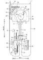
- FIG. 2 is a top view of the inside of the main body viewed from above.
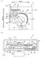
- FIG. 3A is a top view of the inside of the rear side of the main body viewed from above with the switch mounting plate and the switch operation plate removed, and
- FIG. 3B is a rear view of the inside of the main body. It is the rear view seen from. 4A and 4B are diagrams for explaining the slide member.
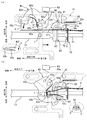
- FIG. 4A is a top view illustrating a state in which the slide member exists at the pre-movement position.
- FIG. It is a top view of the state which exists in a position.
- 5A and 5B are views for explaining a wrapping arm and the like.
- FIG. 5A is a top view in a state where the wrapping arm is at a position before rotation
- FIG. It is a top view in the state where an arm exists in a winding completion position.
- FIG. 6A is a top view of the rotating disk and the switch operation plate before the first switch is pressed and rotated
- FIG. 6B is a rotating disk when the second switch is pressed and stopped.
- FIG. 4 is a top view of a switch operation plate.
- the binding machine 10 is a machine that winds a binding material 2 in the form of a string around the binding object 1 and then twists and binds the binding material 2.
- a binding machine 10 shown in FIG. 1 includes a main body 11 that ties the object 1 to be bound, a main body support 12 that is integrated below the main body 11 and supports the main body 11, And a reel stand 18 attached to the rear side.
- a movement passage (slot) 13 through which the material 1 to be bound is moved to a binding execution position 13a where binding is performed is formed in the main body portion 11 by notch. Details of the main body 11 will be described later.
- the entrance side of the moving passage 13 is referred to as “front side”, and the opposite side is referred to as “rear side”.
- the moving passage 13 extends straight in the front-rear direction. Further, a direction orthogonal to the front-rear direction is referred to as a “width direction”. Further, “right side” or “left side” is used as a direction when the binding machine 10 is viewed from the front side.
- the main body support 12 is covered with the outer case 17 together with the main body 11.
- a power switch is provided on the outer surface of the main body support portion 12, and a power cord is connected thereto. Electrical components are accommodated in the main body support portion 12 (not shown).
- a leg is provided below the main body support 12.
- the winding stand 15 is attached to the reel stand 18.
- the binding material 2 is wound around the winding reel 15.
- a string-like binding material in which a metal or resin core is incorporated in a resin string (eg, a vinyl string) or a paper string can be used.
- the main body unit 11 includes a feeding device 20, a winding device 40, a twisting device 60, and a cutting device 70.
- An insertion port 16 for inserting the binding material 2 unwound from the winding reel 15 is formed on the rear surface of the main body 11.
- a binding material passage 14 for guiding an end of the binding material 2 inserted from the insertion opening 16 to a predetermined position where the binding material 2 can be wound (a predetermined position) is formed inside the main body 11.
- the position where the binding material 2 can be wound is a position where the binding material 2 can be wound around the material 1 to be bound by a winding arm 42 described later.
- the binding material passage 14 extends horizontally forward from the insertion opening 16 in the main body 11, and a hole of a fixed blade 71 described later serves as an outlet 14 a of the binding material passage 14.
- the insertion port 16 is provided at a position on the left side in the width direction, which is closer to the outside.
- the outlet 14a of the binding material passage 14 opens at a position on the left side of the moving passage 13 near the center in the width direction.
- the binding material 2 delivered by the delivery device 20 described below travels along the movement path 13 in an area adjacent to the movement path 13 from the outlet 14a of the binding material path 14 to a position where the binding material can be wound.
- a binding material passage 14 and the like are configured. Specifically, in a top view, the binding material passage 14 bends inward behind a portion sandwiched between a driving roller 23 and a driven roller 24, which will be described later, and extends obliquely to a position slightly behind the outlet 14a. . And it extends substantially forward from a little rear side of the outlet 14a to the outlet 14a. Strictly speaking, the outlet 14a of the binding material passage 14 is slightly outward (left side).
- a rotating arm 91 described later is arranged at the left front of the outlet 14a. Therefore, the binding material 2 sent forward from the outlet 14 a of the binding material passage 14 advances slightly obliquely toward the outside, hits the rotating arm 91, and the traveling direction is corrected forward. Thus, the binding material 2 sent forward from the outlet 14a is prevented from entering the moving passage 13.
- a plurality of support plates to which various components described later are attached are stacked and fixed to each other (see FIG. 3B).
- the support plate portion 30 including the plurality of support plates is fixed to the outer case 17.
- the delivery device 20 is a device that delivers the binding material 2 forward after the binding of the binding object 1 is completed.
- the delivery device 20 includes a motor 21, a rotating disk 22 connected to a rotating shaft 21 a of the motor 21, a driving roller 23 to which rotational force is transmitted from the rotating disk 22, A driven roller 24 that sandwiches the binding material 2 together with the roller 23, a roller elastic member 25 that presses the driven roller 24 against the driving roller 23, and a switch that covers the rotating disk 22 and the like and has a second switch 82 described below provided on the upper surface It has a mounting plate 26 and a switch operation plate 27 mounted on the rotary shaft 21a on the switch mounting plate 26.
- the motor 21 is arranged inside the main body support 12.
- FIG. 3A shows a state in which the switch mounting plate 26 and the switch operation plate 27 have been removed, and the formation region of the rear gear 22c and the torsion gear 63 is hatched.
- FIG. 3B the illustration of the roller elastic member 25 and the like is omitted.
- the axis of the rotating shaft 21a extends in the up-down direction. This is the same for the other rotating shafts 23a, 24a, 28a, 42a, and 91a.
- the rotating disk 22 is a substantially circular plate-like member in plan view. As shown in FIG. 3B, the rotating disk 22 is provided with a front gear 22b and a rear gear 22c.
- the front gear 22b is a gear for rotating the drive roller 23.
- the front gear 22b is, for example, a spur gear, and is provided only in a part of the angle range of the rotating disk 22.
- the back side gear 22c is a gear for rotating a torsion shaft 61 described later.
- the back side gear 22c is, for example, a face gear, and is formed only in a part of the angle range of the rotating disk 22.
- the drive roller 23 is disposed slightly before the insertion port 16.
- the drive roller 23 is rotatably attached to a rotation shaft 23 a fixed to the support plate 30.
- the drive roller 23 is integrated with a roller-side gear 23b that meshes with the front-side gear 22b.
- the roller-side gear 23 b is, for example, a spur gear, and is formed over the entire circumference of the drive roller 23.
- the driven roller 24 is disposed at a position facing the driving roller 23.
- the driven roller 24 is rotatably attached to a rotation shaft 24 a fixed to the support member 28.
- the support member 28 is rotatably supported by a rotation shaft 28 a fixed to the support plate 30.
- the position of the driven roller 24 is determined by a pressing position (the position shown in FIG. 3A) for pressing the driving roller 23 with the rotation of the support member 28 and a separating position separated from the driving roller 23 (the left side of FIG. 3A). Position).
- the driven roller 24 at the pressing position contacts the drive roller 23 on the binding material path 14.
- a lever 29 that extends rearward from the outer case 17 is fixed to the support member 28. Further, one end of a roller elastic member 25 is attached to the lever 29. The other end of the roller elastic member 25 is attached to the hook 26a of the switch attachment plate 26 in a state where the other end is longer than the natural length.
- the support roller 28 is rotated clockwise in FIG. 3A, and the driven roller 24 integrated with the support member 28 is pressed against the drive roller 23 at the pressing position.
- the support member 28 rotates counterclockwise, and the driven roller 24 moves to the separated position.
- the binding material 2 unwound from the winding reel 15 and inserted from the insertion opening 16 can be sandwiched between the driving roller 23 and the driven roller 24.
- a coil spring can be used as the elastic member 25 for the roller.
- the rotating disk 22 rotates. Then, in a part of the rotation angle range in one rotation of the rotating disk 22, the front gear 22b and the roller gear 23b mesh with each other, and the rotational force of the motor 21 is transmitted to the drive roller 23.
- the driving roller 23 rotates with the binding material 2 sandwiched between the driving roller 23 and the driven roller 24, the driven roller 24 also rotates with the rotation, and the binding material 2 is sent forward.
- the switch operation plate 27 When the motor 21 rotates, the switch operation plate 27 also rotates above the switch mounting plate 26 on which the second switch 82 is mounted on the upper surface.
- the switch operation plate 27 is a cam whose distance from the center of the rotating shaft 21a to the outer periphery changes in the circumferential direction.
- a bulging portion 27a bulging outward is formed in a part of the angular range in the circumferential direction. While the switch operation plate 27 is rotating, the second switch 82 is switched by the bulging portion 27a during a period in which the bulging portion 27a faces the second switch 82.
- the wrapping device 40 is a device that automatically wraps the binding material 2 around the tied object 1 using the force of moving the tied object 1 to the binding execution position 13a.
- the winding device 40 includes a slide member 41 provided slidably, a winding arm 42 provided rotatably, a power transmission unit 43 for transmitting power from the slide member 41 to the winding arm 42, and a slide member.
- the slide member 41 includes a slide direction restricting portion 44 for restricting a slide direction of the slide member 41 and a slide return portion 45 for urging the slide member 41 forward by a restoring force.
- the slide member 41 corresponds to a movable member that is moved by being pushed by the binding object 1 that is moving toward the binding execution position 13a from the pre-movement position where at least a part is arranged in the movement passage 13.
- the winding arm 42 is equivalent to a winding member that winds the binding material 2 sent out to a predetermined position by the delivery device 20 around the material 1 to be bound by the rotation of the slide member 41 when the power of the slide member 41 is transmitted.
- the slide return portion 45 corresponds to an elastically deforming portion that returns the slide member 41 to the position before the movement by the restoring force and returns the winding arm 42 to the position before the rotation before rotating for winding the binding material 2.
- the sliding member 41 is connected to one side (left side) of the moving passage 13 in the crossing portion 41a and traverses the moving passage 13 and is slidably supported. It has a slide support portion 41b and a second slide support portion 41c connected to the other side (right side) of the moving passage 13 in the cross section 41a and slidably supported.
- the crossing portion 41 a is formed in a straight long plate shape, and extends substantially perpendicular to the extending direction of the moving passage 13.
- a concave portion 41d into which the binding object 1 enters is formed on the front side of a portion of the crossing portion 41a that straddles the moving passage 13. Thereby, the binding object 1 that pushes the slide member 41 is less likely to shift in the width direction of the moving passage 13.
- the first slide support portion 41b includes an inner portion 41e that extends outward (leftward) from the transverse portion 41a, and a long plate-shaped outer portion 41f that is formed continuously with the inner portion 41e and extends in the front-rear direction. I have.
- An elongated hole 43a constituting the power transmission unit 43 is formed in the inner part 41e.
- a rear outer peripheral portion 92b for pressing a projecting pin 92a described later is formed behind the inner portion 41e.
- two long holes 44a constituting the slide direction regulating portion 44 are formed in the outer portion 41f.
- a protruding portion 41h that contacts a first switch 81 described later is formed at a rear end portion of the outer portion 41f.
- the second slide support portion 41c is a long plate-shaped portion formed continuously outside the transverse portion 41a and extending in the front-rear direction.
- the second slide support portion 41c has one elongated hole 44a constituting the slide direction regulating portion 44.
- a second elastic member 52 constituting the slide return portion 45 is attached to a pin 41i protruding from the upper surface of the second slide support portion 41c.
- the slide direction restricting portion 44 includes the above-described three elongated holes 44a extending in the front-rear direction and the three restriction pins 44b inserted into the three long holes 44a, respectively, and changes the sliding direction of the slide member 41 in the front-rear direction (moving direction). (Extending direction of the passage 13).
- the three long holes 44a have the same length in the front-rear direction.
- the three regulating pins 44b are arranged so that their positions in the front-rear direction with respect to the elongated holes 44a into which the three regulating pins 44b are inserted are the same.
- the sliding range of the slide member 41 is from a pre-movement position before being pushed by the binding object 1 (a position in FIG.
- the slide return portion 45 includes a first elastic member 51 that pulls the first slide support portion 41b forward, and a second elastic member 52 that pulls the second slide support portion 41c forward.
- the first elastic member 51 corresponds to a first spring portion that applies a restoring force for returning the slide member 41 to the pre-movement position to the first slide support portion 41b.
- the second elastic member 52 corresponds to a second spring portion that applies a restoring force for returning the slide member 41 to the position before the movement to the second slide support portion 41c.
- a coil spring is used for each of the elastic members 51 and 52.
- each of the first spring portion and the second spring portion is constituted by one elastic member 51, 52, but may be constituted by a plurality of elastic members.
- first elastic member 51 is attached to a support pin 30a fixed to the support plate portion 30, and the other end is attached to an insertion pin 43b inserted into the elongated hole 43a of the first slide support portion 41b.
- second elastic member 52 has one end attached to a support pin 30b fixed to the support plate 30, and the other end attached to a pin 41i of the second slide support 41c.
- the first elastic member 51 has a larger spring constant between the first elastic member 51 and the second elastic member 52. That is, between the first spring portion and the second spring portion, the first spring portion has a larger restoring force for returning the slide member 41 to the pre-movement position.
- the restoring force applied to the first slide support portion 41b provided with the power transmission portion 43 to the wrapping arm 42 is greater than the restoring force applied to the second slide support portion 41c not provided with the power transmission portion 43. It is larger than the restoring force to be applied. Therefore, the slide member 41 can be returned with good balance on both the left and right sides of the moving passage 13.
- the winding arm 42 is rotatably supported by a rotation shaft 42 a fixed to the support plate 30.
- the winding arm 42 is at the pre-rotation position (the position in FIG. 5A) when the slide member 41 is at the pre-movement position. In this state, the entire winding arm 42 is located on the left side of the moving passage 13. Then, in conjunction with sliding the slide member 41 toward the movement stop position, the winding arm 42 rotates counterclockwise in FIG. 5A, and when the slide member 41 reaches the movement stop position, the winding arm 42 winds.
- the hanging arm 42 reaches the winding completion position (the position shown in FIG. 5B).
- the winding arm 42 includes a plate-shaped arm portion 42b and a binding material holding portion 42c attached to a tip end of the arm portion 42b.
- the winding arm 42 and a donating device 90 to be described later are indicated by solid lines, and a member overlapping the sliding arm 42 and the slide member 41 are indicated by broken lines.
- the arm portion 42b has a planar shape in which a band-like portion extends from a substantially rectangular center portion to which the rotation shaft 42a is attached and is bent in the middle.
- An insertion pin 43b that constitutes the power transmission unit 43 and is inserted into the elongated hole 43a is fixed to the arm 42b in the vicinity of the rotation shaft 42a.
- the belt-like portion extends diagonally forward left and extends diagonally right forward from the bent portion.
- a concave portion 42d which is depressed outside is formed in order to avoid interference with the binding object 1 when rotating to the winding completion position. As shown in FIG.
- the concave portion 42d at the winding completion position forms a hole through which the object 1 can be passed up and down together with the concave portion 41d. Further, the concave portion 42d is provided with a leaf spring member 47 for suppressing the binding material 2 from separating from the binding object 1 when the binding material 2 is wound around the small binding object 1.
- a bulge 42e for switching the third switch 83 is formed at a position outside the rear end of the arm 42b at the pre-rotation position.
- the bulging portion 42e contacts the third switch 83 at the pre-rotation position, and separates from the third switch 83 when the winding arm 42 rotates counterclockwise from the pre-rotation position.
- the binding material holder 42c is a small piece having a substantially rectangular plate shape.
- a view of the binding body holding portion 42c as viewed from the front side is shown in a broken line at the lower left of FIG.
- the binding material holding portion 42c is fixed to the distal end of the arm portion 42b so as to protrude toward the moving passage 13 side.
- the short side of the binding material holding portion 42c extends in the vertical direction, and is orthogonal to the arm portion 42b.
- a concave portion 42f into which the binding material 2 fits is formed at the tip of the binding material holding portion 42c.
- the power transmission unit 43 includes an elongated hole 43a formed on one of the slide member 41 and the winding arm 42, and an insertion pin fixed to the other of the slide member 41 and the winding arm 42 and inserted through the elongated hole 43a. 43b.
- the power transmission unit 43 is configured to transmit power from the slide member 41 to the winding arm 42 to rotate the winding arm 42 when the sliding member 41 slides forward or backward.
- the power transmission unit 43 converts the movement of the slide member 41 in the sliding direction into a rotational movement and transmits the power to the winding arm 42.
- the long hole 43a is formed in the inner part 41e of the first slide support part 41b.
- the extending direction of the elongated hole 43a is slightly inclined with respect to the direction (width direction) orthogonal to the sliding direction of the slide member 41 so that the inside (right side) is located on the front side compared to the outside (left side). Further, the insertion pin 43b is fixed to the winding arm 42.
- the insertion pin 43b is located outside the elongated hole 43a. In this state, the insertion pin 43b is located on the front side and inside the rotation shaft 42a.
- the insertion pin 43b is pushed rearward by the front portion of the elongated hole 43a.
- the winding arm 42 rotates counterclockwise in FIG. 5A while the insertion pin 43b moves in the elongated hole 43a.
- the winding arm 42 reaches the winding completion position (the position in FIG. 5B). Since the slide range of the slide member 41 is restricted, the rotation range of the winding arm 42 is also restricted.
- the winding arm 42 is rotatable in a range from a pre-rotation position to a winding completion position.
- the winding arm 42 in order to wind the binding material 2, it is necessary to relatively rotate the winding arm 42. To that end, it is conceivable to increase the sliding range of the sliding member 41. However, when the sliding range of the slide member 41 is increased, the distance for pressing the slide member 41 for the user becomes long. Also, the winding arm 42 can be largely rotated by reducing the distance between the axes of the rotation shaft 42a and the insertion pin 43b. However, in this case, the force required to move the slide member 41 increases. Therefore, in the present embodiment, in a state where the slide member 41 is at the pre-movement position, the rotation center of the winding arm 42 is set so that the force required to move the slide member 41 while holding down the slide range does not become too large. The distance X to the point of action A at which the force transmitted from the slide member 41 acts on the winding arm 42 is set within a numerical range of 0.5 cm or more and 3 cm or less.
- the torsion device 60 includes a torsion shaft 61 rotatably provided, a hook 62 fixed to one end (front end) of the torsion shaft 61, and a torsion device as shown in FIG.
- a torsion-side gear 63 is provided at the other end (rear end) of the shaft 61.
- the torsion shaft 61 extends in the front-rear direction from a position slightly behind the moving passage 13 to a position slightly forward of the rotating shaft 21 a of the rotating disk 22.
- the other end of the torsion shaft 61 overlaps the lower side of the front part of the rotating disk 22.
- the axis of the torsion shaft 61 coincides with the center of the moving passage 13 in the width direction.
- the twist gear 63 is, for example, a spur gear, and meshes with the rear gear 22 c of the rotating disk 22.
- the back side gear 22c and the torsion side gear 63 are designed so that the torsion shaft 61 just rotates by a natural number times (for example, three times) when the rotating disk 22 makes one rotation. Therefore, when the rotating disk 22 makes one rotation, the hook portion 62 and a movable blade 72 described later return to the same rotational position as before rotation.
- the hook portion 62 twists the binding material 2 by rotating while the binding material 2 wound around the binding object 1 is hooked. Specifically, the hook portion 62 hooks the binding material 2 wound around the binding object 1 with respect to each of the near side and the tip side of the folded portion when the torsion shaft 61 rotates.
- a view of the hook portion 62 as viewed from the front side is shown in the broken line at the lower right of FIG.
- the hook portion 62 is a substantially S-shaped or substantially Z-shaped member having a hook that hooks on the binding material 2 on the front side of the folded portion and a hook that hooks on the binding material 2 on the distal end side of the folded portion.
- the hook portion 62 is disposed slightly behind the binding execution position 13 a in the moving passage 13.
- the cutting device 70 includes a fixed blade 71 fixed to the support plate 30 and a movable blade 72 fixed to the torsion shaft 61 at a position adjacent to the front side of the fixed blade 71. Have.
- the cutting device 70 also serves as the twist device 60 and the twist shaft 61.
- the fixed blade 71 is located at the outlet 14 a of the binding material passage 14 in the front-rear direction.
- the cutting device 70 cuts the front side of the folded portion of the binding material 2 at the outlet 14 a of the binding material passage 14.
- the binding machine 10 further includes a donating device 90 for bringing the binding material 2 to the twisting shaft 61 side before the binding material 2 is twisted by the twisting device 60.
- the donating device 90 transmits power from the sliding member 41 to the rotating arm 91, which is rotatably supported by a rotating shaft 91 a fixed to the support plate 30.
- a resilient member 93 that urges the rotating arm 91 by a restoring force.
- the rotating arm 91 is a plate-like member extending forward from the rotating shaft 91a.
- the rotating arm 91 is bent inward on the way.
- the portion from the rotating shaft 91a to the bent portion extends diagonally forward left, and the portion from the bent portion to the tip portion extends diagonally right forward.
- a protruding portion 91 b bulging inward is formed on the rear side of the rotating arm 91.
- each of the protruding portion 91b and the tip portion 91c protrudes inward (toward the moving passage 13).
- the binding material 2 sent forward from the outlet 14a of the binding material passage 14 hits the protrusion 91b of the rotating arm 91 at the pre-rotation position. Specifically, the binding material 2 hits the side surface behind the tip in the protruding portion 91b.
- the rear side surface of the projecting portion 91b at the pre-rotation position extends obliquely rightward toward the front in a plan view, and corrects the traveling direction of the binding material 2 sent out from the outlet 14a of the binding material passage 14 to a substantially forward direction. I do.
- the power transmission unit 92 includes a protruding pin 92a fixed to an outer position of the rotary arm 91, and a rear outer peripheral portion 92b of the inner portion 41e of the first slide support portion 41b.
- the rear outer peripheral portion 92b extends obliquely so as to be closer to the inside (toward the moving passage 13) toward the front. Therefore, when the sliding member 41 comes into contact with the protruding pin 92a in the process of sliding backward, the protruding pin 92a gradually moves inward, and the rotating arm 91 rotates counterclockwise in FIG. I do. During this rotation, the rotating arm 91 has the protruding portion 91b and the distal end portion 91c contact the binding material 2 on the near side of the folded portion from outside, and bring the binding material 2 inward at two locations.
- the elastic member 93 urges the rotating arm 91 from the pre-rotation position to a direction opposite to the rotation direction of the donation completion position.
- a coil spring can be used as the elastic member 93.
- One end of the elastic member 93 is attached to a support pin 30 c fixed to the support plate portion 30, and the other end is attached to a protruding piece provided at a position near the rotation arm 91. In the process of sliding the slide member 41 forward, the elastic member 93 returns the rotary arm 91 to the pre-rotation position.
- the binding machine 10 includes a first switch 81, a second switch 82, and a third switch 83 for turning the motor 21 on or off.
- Each of the first switch 81 and the third switch 83 is a switch that switches the motor 21 to an ON state when a contact is made.
- the second switch 82 is a switch that switches the motor 21 to the OFF state both when the contact contacts and when the contact separates.
- the first switch 81 is pressed by the protrusion 41h of the slide member 41 at the timing when the slide member 41 slides backward and reaches the movement stop position, and is switched to the ON state (see FIG. 4B).
- the first switch 81 switches to the ON state
- power is supplied to the motor 21 and the rotation of the motor 21 starts.
- each of the rotating disk 22 and the switch operation plate 27 starts rotating clockwise from the state shown in FIG.
- the second switch 82 is pressed by the bulging portion 27a of the switch operation plate 27 as shown in FIG. Then, the contact of the second switch 82 comes into contact, and the motor 21 switches to the OFF state.
- the switch operation plate 27 stops in a state where the front side of the bulging portion 27a in the rotation direction contacts the second switch 82.
- the third switch 83 is pressed by the bulging portion 42e of the winding arm 42 at the timing when the winding arm 42 returns to the pre-rotation position, and is switched to the ON state (see FIG. 5A).
- the third switch 83 is switched to the ON state, power is supplied to the motor 21 and the rotation of the motor 21 is started. As a result, each rotation of the rotating disk 22 and the switch operation plate 27 is started again.
- the switch operation plate 27 rotates by a predetermined angle from the state of FIG. 6B, the bulging portion 27a of the switch operation plate 27 separates from the second switch 82 (see FIG. 6A). Then, the contact point of the second switch 82 is also separated, and the motor 21 is stopped.
- first rotation period the period until the motor 21 is switched to the ON state by the first switch 81 and stopped (hereinafter, referred to as “first rotation period”), the front side gear 22b does not mesh with the roller side gear 23b above the rotating disk 22.
- the lower gear 22 c meshes with the torsion gear 63 below the rotating disk 22.
- first rotation period only the torsion shaft 61 of the drive roller 23 and the torsion shaft 61 rotates.
- hatching is applied to each of the formation regions of the back gear 22c and the torsion gear 63.
- the front side gear 22b meshes with the roller side gear 23b above the rotating disk 22 to rotate.
- the back side gear 22 c does not mesh with the torsion side gear 63.
- the second rotation period only the drive roller 23 of the drive roller 23 and the torsion shaft 61 rotates.
- the binding object 1 When the user moves the binding object 1 from the entrance of the moving passage 13 toward the binding execution position 13a, the binding object 1 traverses the slide member 41 in the middle of the moving passage 13 as shown in FIG.
- the slide member 41 hit by the user at the position of the concave portion 41d in the portion 41a starts sliding backward from the pre-movement position.
- the sliding motion of the slide member 41 is converted into the rotational motion of the winding arm 42 via the power transmission unit 43, and the winding arm 42 rotates counterclockwise.
- the concave portion 42f of the binding material holding portion 42c is hooked on the end of the binding material 2.
- the binding material 2 held in the concave portion 42f is bent so as to be folded back to the side sent out by the sending-out device 20, as shown in FIG. 1 reaches the binding execution position 13a.
- the slide member 41 stops sliding at the movement stop position, and the winding arm 42 stops rotating at the winding completion position. In this state, as shown in FIG. 5B, the binding material 2 is wound around the material 1 to be bound.
- the rear outer peripheral portion 92b of the slide member 41 comes into contact with the protruding pin 92a of the rotating arm 91 and starts pushing the donation device 90. Then, when the slide member 41 further slides rearward, as shown in FIG. 5B, the protruding pin 92a moves inward, and the rotary arm 91 rotates to the donation completion position. As a result, the protruding portion 91b and the distal end portion 91c of the rotating arm 91 come into contact with the binding material 2 on the front side of the folded portion from the outside, and bring the binding material 2 toward the twist shaft 61 at two locations. As a result, the binding material 2 is securely pushed into the hook of the hook 62.
- the first switch 81 is pressed by the protruding portion 41h of the slide member 41 to be turned on, and the motor 21 is driven. I do.
- the first rotation period starts, and the rotating disk 22 rotates from the state shown in FIG.
- the torsion shaft 61 rotates as described above.
- the first rotation period ends when the second switch 82 is pressed by the switch operation plate 27 and the motor 21 stops.
- the torsion shaft 61 rotates by a predetermined number of rotations. As a result, the binding material 2 is cut, and at the same time, the binding material 2 hooked on the hook portion 62 is twisted, and the binding of the binding object 1 is completed.
- a preparation operation for binding the next binding object 1 is performed. Specifically, when the user moves the binding object 1 out of the movement passage 13 after the binding is completed, the user's force is removed from the slide member 41, and the slide member 41 is moved by the first elastic member 51 and the second elastic member 52. Is returned to the position before the movement.
- the winding arm 42 returns to the pre-rotation position, and the rotation arm 91 also returns to the pre-rotation position.
- the third switch 83 is pressed by the bulging portion 42e of the winding arm 42, and the motor 21 is driven again.
- the second rotation period starts, and the rotating disk 22 rotates from the state of FIG. 6B.
- the drive roller 23 rotates as described above.
- the second rotation period ends when the switch operation plate 27 separates from the second switch 82 and the motor 21 stops, as shown in FIG.
- the drive roller 23 rotates by a predetermined number of rotations. Thereby, the end of the binding material 2 located near the outlet 14a of the binding material passage 14 is fed to a position where the binding material can be wound.
- the binding material 2 is wound around the binding object 1 using the force for moving the binding object 1 to the binding execution position 13a. Therefore, there is no need to transmit the power of the motor 21 to the wrapping arm 42, and components that complicate the mechanical configuration in the conventional binding machine can be omitted. Therefore, it is possible to provide the binding machine 10 capable of simplifying the mechanical configuration.
- the preparation for the next binding is automatically performed after the binding of the binding object 1 is completed. Can be done with
- the twisting device 60 is driven by automatically driving the motor 21 using the movement of the slide member 41 when moving the binding object 1 to the binding execution position 13a. Further, the motor 21 is automatically driven by utilizing the movement when the winding arm 42 is returned, and the feeding device 20 is driven. Therefore, the binding machine 10 can be automated with a simple configuration.
- the binding material 2 is brought closer to the twisting shaft 61 before the binding material 2 is twisted by using the force for moving the binding object 1 to the binding execution position 13a. Therefore, the binding member 2 can be reliably twisted by the hook portion 62.
- the slide return portion 45 for applying a restoring force to the slide member 41 is provided as the elastically deformable portion.
- the elastic member of the elastically deformable portion is connected to the winding arm 42 and restored to the winding arm 42. A force may be applied. In this case, the power is transmitted from the winding arm 42 to the slide member 41, and the slide member 41 returns to the pre-movement position.
- the slide member 41 is provided as the movable member, but the movement of the movable member is not limited to the slide.
- the movable member may be a member that is rotated by a force that moves the binding target object 1 to the binding execution position 13a.
- the movable members are provided with the slide support portions 41b and 41c on both sides of the moving passage 13, but the slide support portions may be provided on only one side of the moving passage 13.
- the movable member only needs to be at least partially arranged in the movement passage 13 at the pre-movement position, and does not have to cross the movement passage 13.
- the slide member 41 and the winding arm 42 are formed with the elongated hole 43 a in the slide member 41 and the insertion pin 43 b is fixed to the winding arm 42. May be formed with an elongated hole 43a, and the insertion pin 43b may be fixed to the slide member 41.
- the first switch 81 may be switched to the ON state by the winding arm 42 instead of the slide member 41.
- the third switch 83 may be switched to the ON state by the slide member 41 instead of the winding arm 42.
- the present invention is applicable to a binding machine or the like that binds an object to be bound by winding the binding material around the object and twisting the object.
Landscapes
- Engineering & Computer Science (AREA)
- Mechanical Engineering (AREA)
- Basic Packing Technique (AREA)
Abstract
結束機10は、結束材2を送り出す送り出し装置20と、結束実行位置13aに移動させる被結束物1を通過させる移動通路13と、少なくとも一部が移動通路13に配置された移動前位置から、結束実行位置13aに向かって移動中の被結束物1に押されることにより動かされる可動部材41と、移動前位置から動かされる可動部材41の動力が伝達されて回転することにより、送り出し装置20により所定の位置まで送り出された結束材2を被結束物1に巻き掛ける巻き掛け部材42と、巻き掛け部材42により被結束物1に巻き掛けられた結束材2を捻る捻り装置60とを備えている。
Description
本発明は、被結束物に結束材を巻き掛けて捻ることにより被結束物の結束を行う結束機に関する。
従来から、被結束物に結束材を巻き掛けて捻ることにより被結束物の結束を行うタイプの結束機が知られている。例えば、結束機は、紐状の結束材により袋口などを結束するために用いられる。
特許文献1には、物品に結束材を巻き掛けて捻りしめる結束機が記載されている。結束機は、物品結束用の結束材を送り出す送り出し装置と、送り出された結束材を物品周りに巻き掛ける折り曲げ巻き掛け装置と、折り曲げ巻き掛けられた結束材を物品に合わせてさらに巻き込んで締め付け固定するクランプ装置と、結束材を切断する切断装置と、折り曲げ巻き掛けられた結束材を捻りしめる捻り装置と、切断された結束材の後方結束材をはさみ込んで締め付け固定する挿入口クランプ装置と、ケーシング本体の後端部に結束材を供給する補給ドラムを具備している。この結束機は、送り出し円板を所定の方向に回転させることにより、送り出し装置と、挿入口クランプ装置と、切断装置と、捻り装置を作動せしめ、連杆と、送り出し円板に設けられた連杆駆動軸とを回転・横移動自在に連結して、送り出し円板を所定の方向に回転させることにより、折り曲げ巻き掛け装置と、クランプ装置を作動させる。
ところで、従来の結束機では、1つのモータで様々な装置を駆動させるために、送り出し円板に対してモータを設け、動力が必要な他の装置に対しては連杆を介してモータの動力を伝達させている。しかしながら、折り曲げ巻き掛け装置はモータから離れている。そのため、折り曲げ巻き掛け装置に対してモータの動力を伝達させるために、長い部材の連杆や、連杆に連結される連杆駆動軸及びクランプ駆動軸などの部品が必要であり、機械構成が複雑化し、製造コストを低減させることが困難であった。
本発明は、このような事情に鑑みてなされたものであり、被結束物に結束材を巻き掛けて捻ることにより被結束物の結束を行う結束機において、機械構成を簡素化することが可能な結束機を提供することを目的とする。
上述の課題を解決するべく、第1の発明は、被結束物に結束材を巻き掛けて捻ることにより被結束物の結束を行う結束機であって、結束材を送り出す送り出し装置と、結束実行位置に移動させる被結束物を通過させる移動通路と、少なくとも一部が移動通路に配置された移動前位置から、結束実行位置に向かって移動中の被結束物に押されることにより動かされる可動部材と、移動前位置から動かされる可動部材の動力が伝達されて回転することにより、送り出し装置により所定の位置まで送り出された結束材を被結束物に巻き掛ける巻き掛け部材と、巻き掛け部材により被結束物に巻き掛けられた結束材を捻る捻り装置とを備えている。
第2の発明は、第1の発明において、復元力により、移動前位置に可動部材を戻すと共に結束材を巻き掛けるために回転する前の回転前位置に巻き掛け部材を戻す弾性変形部をさらに備えている。
第3の発明は、第2の発明において、可動部材は、移動通路を横断する横断部と、横断部における移動通路の片側に接続されてスライド自在に支持された第1スライド支持部と、横断部における移動通路のもう片側に接続されてスライド自在に支持された第2スライド支持部とを有し、弾性変形部は、移動前位置に可動部材を戻す復元力を第1スライド支持部に作用させる第1バネ部と、移動前位置に可動部材を戻す復元力を第2スライド支持部に作用させる第2バネ部とを有し、可動部材では、巻き掛け部材に動力を伝達させる動力伝達部が第1スライド支持部に設けられ、第1バネ部と第2バネ部とでは第1バネ部の方が、復元力が大きい。
第4の発明は、第1乃至3の何れか1つの発明において、可動部材は、移動通路に沿ってスライド自在に設けられ、可動部材が移動前位置にある状態において、巻き掛け部材の回転中心から、可動部材から伝達される力が巻き掛け部材に作用する作用点までの距離が、0.5cm以上3cm以下である。
第5の発明は、第1乃至4の何れか1つの発明において、被結束物が結束実行位置に到達するタイミングで可動部材又は巻き掛け部材に接触してON状態に切り替わるスイッチと、スイッチがON状態に切り替わると電力が供給されて、捻り装置を駆動させるモータとを備えている。
第6の発明は、第1乃至4の何れか1つの発明において、可動部材が移動前位置に戻るタイミングで可動部材又は巻き掛け部材に接触してON状態に切り替わるスイッチと、スイッチがON状態に切り替わると電力が供給されて、送り出し装置を駆動させるモータとを備えている。
第7の発明は、第1乃至6の何れか1つの発明において、外部から挿入された結束材を所定の位置に案内するための結束材通路をさらに備え、送り出し装置により送り出された結束材が、結束材通路の出口から所定の位置まで、移動通路に沿って該移動通路の隣接領域を進むように構成された。
第8の発明は、第1乃至7の何れか1つの発明において、捻り装置は、回転自在に設けられた捻り軸と、捻り軸に固定されて捻り軸が回転すると被結束物に巻き掛けられた結束材を引っ掛けた状態で回転する引っ掛け部とを有し、移動前位置から動かされる可動部材の動力が伝達されて動かされることにより、捻り装置により結束材が捻られる前に捻り軸側に結束材を寄せ付ける寄付け装置をさらに備えている。
本発明では、結束実行位置に向かって移動中の被結束物に押されて可動部材が動かされ、さらに可動部材の動力が伝達されて回転する巻き掛け部材により、結束材が被結束物に巻き掛けられる。すなわち、結束実行位置に被結束物を移動させる力を利用して、結束材が被結束物に巻き掛けられる。そのため、従来の結束機とは異なり、巻き掛け部材にモータの動力を伝達させる必要がなく、従来の結束機において機械構成を複雑化させていた部品を省略することができる。本発明によれば、被結束物に結束材を巻き掛けて捻ることにより被結束物の結束を行う結束機において、機械構成を簡素化することが可能な結束機を提供することができる。
第2の発明では、移動前位置に可動部材を戻すと共に回転前位置に巻き掛け部材を戻す弾性変形部を設けたため、被結束物への結束完了後に次の結束の準備を自動で行うことができる。
第3の発明では、巻き掛け部材に対する動力伝達部が設けられた第1スライド支持部に作用させる復元力の方が、第2スライド支持部に作用させる復元力より大きくしている。そのため、移動前位置に可動部材を戻す力のバランスを移動通路の両側で取ることができ、可動部材を安定して戻すことができる。
第4の発明では、巻き掛け部材の回転中心から、可動部材から伝達される力が巻き掛け部材に作用する作用点までの距離(以下、「中心-作用点距離」という。)が、0.5cm以上3cm以下である。ここで、結束材の巻き掛けを行うためには、巻き掛け部材を比較的大きく回転させる必要がある。そのためには、スライド部材のスライド範囲を大きくすることが考えられる。しかし、スライド部材のスライド範囲を大きくした場合、ユーザにとってスライド部材を押す距離が長くなる。また、中心-作用点距離を短くすることでも、巻き掛け部材を大きく回転させることが可能である。しかし、この場合は、スライド部材を動かすために必要な力が大きくなる。そこで、本発明では、中心-作用点距離を0.5cm以上3cm以下とすることで、スライド範囲を押さえつつスライド部材を動かすために必要な力が大きくなり過ぎないようにしている。そのため、可動部材を押すユーザの負担が増大することを抑制することができる。
第5の発明では、被結束物を結束実行位置に移動させる時の可動部材又は巻き掛け部材の動きを利用して、捻り装置を駆動させるモータが自動的に駆動するようにしている。そのため、簡素な構成で結束機の自動化を図ることができる。
第6の発明では、可動部材又は巻き掛け部材を戻す時の動きを利用して、送り出し装置を駆動させるモータが自動的に駆動するようにしている。そのため、簡素な構成で結束機の自動化を図ることができる。
第7の発明では、送り出し装置により送り出された結束材が、結束材通路の出口から、巻き掛け部材による被結束物への巻き掛けが可能な所定の位置まで、移動通路に沿って移動通路の隣接領域を進む。そのため、結束材の移動通路への侵入により被結束物の移動が阻害されることを確実に防止することができる。
第8の発明では、結束実行位置に被結束物を移動させる力を利用して、結束材が捻られる前に捻り軸側に結束材を寄せ付けている。結束材の位置は、引っ掛け部の回転中心に近づく。そのため、引っ掛け部により結束材を確実に捻ることができる。
以下、図1-図6を参照しながら、本発明の実施形態を詳細に説明する。なお、以下の実施形態は、本発明の一例であって、本発明、その適用物、あるいはその用途の範囲を制限することを意図するものではない。
[結束機の概略構成]
結束機10は、被結束物1に対し紐状の結束材2を巻き掛けた後に捻って結束する機械である。図1に示す結束機10は、被結束物1の結束を行う本体部11と、本体部11の下側に一体化されて本体部11を支持する本体支持部12と、本体支持部12の後ろ側に取り付けられたリールスタンド18とを備えている。本体部11には、結束が実行される結束実行位置13aに移動させる被結束物1を通過させる移動通路(スロット)13が切り欠きにより形成されている。本体部11についての詳細は後述する。
結束機10は、被結束物1に対し紐状の結束材2を巻き掛けた後に捻って結束する機械である。図1に示す結束機10は、被結束物1の結束を行う本体部11と、本体部11の下側に一体化されて本体部11を支持する本体支持部12と、本体支持部12の後ろ側に取り付けられたリールスタンド18とを備えている。本体部11には、結束が実行される結束実行位置13aに移動させる被結束物1を通過させる移動通路(スロット)13が切り欠きにより形成されている。本体部11についての詳細は後述する。
以下では、移動通路13の入口側を「前側」、その反対側を「後ろ側」と言う。移動通路13は前後方向に真っすぐ延びている。また、前後方向に直交する方向を「幅方向」と言う。また、「右側」又は「左側」は、結束機10を前側から見た場合の方向として用いる。
本体支持部12は、本体部11と共に外装ケース17により被覆されている。本体支持部12の外面には電源スイッチが設けられると共に、電源コードが接続されている。本体支持部12には、電装品が収容されている(図示省略)。本体支持部12の下部には脚部が設けられている。また、リールスタンド18には巻付リール15が取り付けられている。巻付リール15には結束材2が巻き付けられる。結束材2としては、樹脂紐(ビニール紐など)や紙製の紐に金属製や樹脂製の芯材が内蔵された紐状結束材などを使用することができる。
[本体部の概略構成]
本体部11は、図2に示すように、送り出し装置20と、巻き掛け装置40と、捻り装置60と、切断装置70とを備えている。本体部11の後ろ面には、巻付リール15から巻き出した結束材2を挿入する挿入口16が形成されている。また、本体部11の内部には、挿入口16から挿入された結束材2の端部を所定の巻き掛け可能位置(所定の位置)に案内するための結束材通路14が形成されている。巻き掛け可能位置は、後述する巻き掛けアーム42により被結束物1に結束材2を巻き掛けることができる位置である。
本体部11は、図2に示すように、送り出し装置20と、巻き掛け装置40と、捻り装置60と、切断装置70とを備えている。本体部11の後ろ面には、巻付リール15から巻き出した結束材2を挿入する挿入口16が形成されている。また、本体部11の内部には、挿入口16から挿入された結束材2の端部を所定の巻き掛け可能位置(所定の位置)に案内するための結束材通路14が形成されている。巻き掛け可能位置は、後述する巻き掛けアーム42により被結束物1に結束材2を巻き掛けることができる位置である。
結束材通路14は、本体部11内において挿入口16から前方に水平に延び、後述する固定刃71の穴が結束体通路14の出口14aとなっている。挿入口16は、幅方向において左側の外寄りの位置に設けられている。結束材通路14の出口14aは、幅方向の中心付近において移動通路13より左側の位置に開口している。
本実施形態では、後述する送り出し装置20により送り出された結束材2が、結束材通路14の出口14aから巻き掛け可能位置まで、移動通路13に沿って移動通路13の隣接領域を進むように、結束材通路14等が構成されている。具体的に、上面視において、結束材通路14は、後述する駆動ローラ23と従動ローラ24に挟まれる箇所の後ろ側で内側に曲がって、出口14aの少し後ろ側までそのまま斜め方向に延びている。そして、出口14aの少し後ろ側から出口14aまでは略前方に延びている。厳密には、結束材通路14の出口14aは少しだけ外側(左側)を向いている。また、出口14aの左前には、後述する回転アーム91が配置されている。そのため、結束材通路14の出口14aから前方に送り出される結束材2は、少し外側を向いて斜めに進み、回転アーム91に当たって進行方向が前方向に矯正される。これにより、出口14aから前方に送り出される結束材2が移動通路13に侵入しないようにしている。
ここで、本体部11における外装ケース17内では、後述する様々な部品が取り付けられている複数の支持プレートが、互いに積層されて固定されている(図3(b)参照)。これらの複数の支持プレートから構成された支持プレート部30は、外装ケース17に固定されている。
[送り出し装置の構成]
送り出し装置20は、被結束物1の結束が完了した後などに結束材2を前方に送り出す装置である。送り出し装置20は、図2及び図3に示すように、モータ21と、モータ21の回転軸21aに連結された回転円盤22と、回転円盤22から回転力が伝達される駆動ローラ23と、駆動ローラ23と共に結束材2を挟み込む従動ローラ24と、駆動ローラ23に従動ローラ24を押し付けるローラ用弾性部材25と、回転円盤22などを被覆して後述する第2スイッチ82が上面に設けられたスイッチ取付板26と、スイッチ取付板26上で回転軸21aに取り付けられたスイッチ操作板27とを備えている。モータ21は本体支持部12の内部に配置されている。なお、図3(a)は、スイッチ取付板26及びスイッチ操作板27を取り外した状態を示し、裏側ギア22cと捻り側ギア63の
形成領域にハッチングを付けている。また、図3(b)ではローラ用弾性部材25などの記載を省略している。また、回転軸21aの軸心は上下方向に延びている。この点は他の回転軸23a,24a,28a,42a,91aも同じである。
送り出し装置20は、被結束物1の結束が完了した後などに結束材2を前方に送り出す装置である。送り出し装置20は、図2及び図3に示すように、モータ21と、モータ21の回転軸21aに連結された回転円盤22と、回転円盤22から回転力が伝達される駆動ローラ23と、駆動ローラ23と共に結束材2を挟み込む従動ローラ24と、駆動ローラ23に従動ローラ24を押し付けるローラ用弾性部材25と、回転円盤22などを被覆して後述する第2スイッチ82が上面に設けられたスイッチ取付板26と、スイッチ取付板26上で回転軸21aに取り付けられたスイッチ操作板27とを備えている。モータ21は本体支持部12の内部に配置されている。なお、図3(a)は、スイッチ取付板26及びスイッチ操作板27を取り外した状態を示し、裏側ギア22cと捻り側ギア63の
形成領域にハッチングを付けている。また、図3(b)ではローラ用弾性部材25などの記載を省略している。また、回転軸21aの軸心は上下方向に延びている。この点は他の回転軸23a,24a,28a,42a,91aも同じである。
回転円盤22は、平面視において略円形の板状部材である。回転円盤22には、図3(b)に示すように、表側ギア22bと裏側ギア22cとが設けられている。表側ギア22bは、駆動ローラ23を回転させるためのギアである。表側ギア22bは、例えば平歯車であり、回転円盤22において一部の角度範囲だけに設けられている。裏側ギア22cは、後述する捻り軸61を回転させるためのギアである。裏側ギア22cは、例えばフェースギアであり、回転円盤22において一部の角度範囲だけに形成されている。
駆動ローラ23は、挿入口16の少し前側に配置されている。駆動ローラ23は、支持プレート部30に固定された回転軸23aに対し回転自在に取り付けられている。駆動ローラ23には、表側ギア22bに噛み合うローラ側ギア23bが一体化されている。ローラ側ギア23bは、例えば平歯車であり、駆動ローラ23の全周に亘って形成されている。
従動ローラ24は、駆動ローラ23に対向する位置に配置されている。また、従動ローラ24は、支持部材28に固定された回転軸24aに回転自在に取り付けられている。支持部材28は、支持プレート部30に固定された回転軸28aに回転自在に支持されている。従動ローラ24の位置は、支持部材28の回転に伴って、駆動ローラ23を押し付ける押付位置(図3(a)の位置)と、駆動ローラ23から離れた離間位置(図3(a)より左側の位置)との間で変化する。押付位置にある従動ローラ24は、結束材通路14上で駆動ローラ23に接触する。
支持部材28には、外装ケース17から後ろ側に延び出るレバー29が固定されている。また、レバー29にはローラ用弾性部材25の一端部が取り付けられている。ローラ用弾性部材25の他端部は、自然長よりも長くした状態で、スイッチ取付板26のフック26aに取り付けられている。これにより、ユーザがレバー29に力を加えない状態では、ローラ用弾性部材25の引張力が、レバー29を介して支持部材28に伝達される。これにより、支持部材28が、図3(a)において時計回りに回転しようとして、支持部材28に一体化された従動ローラ24が押付位置で駆動ローラ23に押し付けられる。また、ローラ用弾性部材25の引張力に抗ってユーザがレバー29を外側に移動させると、支持部材28が反時計回りに回転して従動ローラ24が離間位置に移動する。これにより、巻付リール15から巻き出して挿入口16から挿入した結束材2を駆動ローラ23と従動ローラ24との間に挟み込むことができる。なお、ローラ用弾性部材25には例えばコイルばねを用いることができる。
以上の構成により、モータ21が回転すると、回転円盤22が回転する。そして、回転円盤22の一回転における一部の回転角度範囲において、表側ギア22bとローラ側ギア23bとが噛み合い、モータ21の回転力が駆動ローラ23に伝達される。駆動ローラ23と従動ローラ24との間に結束材2を挟み込んだ状態で駆動ローラ23が回転すると、それに伴って従動ローラ24も回転し、結束材2が前方に送り出される。
また、モータ21が回転すると、上面に第2スイッチ82が取り付けられたスイッチ取付板26の上方で、スイッチ操作板27も回転する。スイッチ操作板27は、回転軸21aの中心から外周までの距離が周方向に変化するカムである。スイッチ操作板27では、周方向において一部の角度範囲において、外側に膨出する膨出部27aが形成されている。スイッチ操作板27の回転中は、膨出部27aが第2スイッチ82に対向する期間に、膨出部27aにより第2スイッチ82が切り替えられる。
[巻き掛け装置の構成]
巻き掛け装置40は、結束実行位置13aに被結束物1を移動させる力を利用して、被結束物1に結束材2を自動的に巻き掛ける装置である。巻き掛け装置40は、スライド自在に設けられたスライド部材41と、回転自在に設けられた巻き掛けアーム42と、スライド部材41から巻き掛けアーム42に動力を伝達させる動力伝達部43と、スライド部材41のスライド方向を規制するスライド方向規制部44と、復元力によりスライド部材41を前側に付勢するスライド戻し部45とを備えている。
巻き掛け装置40は、結束実行位置13aに被結束物1を移動させる力を利用して、被結束物1に結束材2を自動的に巻き掛ける装置である。巻き掛け装置40は、スライド自在に設けられたスライド部材41と、回転自在に設けられた巻き掛けアーム42と、スライド部材41から巻き掛けアーム42に動力を伝達させる動力伝達部43と、スライド部材41のスライド方向を規制するスライド方向規制部44と、復元力によりスライド部材41を前側に付勢するスライド戻し部45とを備えている。
スライド部材41は、少なくとも一部が移動通路13に配置された移動前位置から、結束実行位置13aに向かって移動中の被結束物1に押されることにより動かされる可動部材に相当する。また、巻き掛けアーム42は、スライド部材41の動力が伝達されて回転することにより、送り出し装置20により所定の位置まで送り出された結束材2を被結束物1に巻き掛ける巻き掛け部材に相当する。スライド戻し部45は、復元力により、移動前位置にスライド部材41を戻すと共に結束材2を巻き掛けるために回転する前の回転前位置に巻き掛けアーム42を戻す弾性変形部に相当する。
スライド部材41は、図4(a)に示すように、移動通路13を横断する横断部41aと、横断部41aにおける移動通路13の片側(左側)に接続されてスライド自在に支持された第1スライド支持部41bと、横断部41aにおける移動通路13のもう片側(右側)に接続されてスライド自在に支持された第2スライド支持部41cとを備えている。
横断部41aは、真っすぐな長板状に形成され、移動通路13の延伸方向に対し略垂直に延びている。横断部41aにおいて移動通路13に跨る箇所の前側には、被結束物1が入り込む凹部41dが形成されている。これにより、スライド部材41を押す被結束物1が移動通路13の幅方向にずれにくくなる。
第1スライド支持部41bは、横断部41aから外側(左側)に向かって広がる内側部41eと、内側部41eに連続して形成されて前後方向に延びる長板状の外側部41fとを備えている。内側部41eには、動力伝達部43を構成する長穴43aが形成されている。また、内側部41eの後ろ側には、後述する突出ピン92aを押す後ろ側外周部92bが形成されている。一方、外側部41fには、スライド方向規制部44を構成する2つの長穴44aが形成されている。また、外側部41fにおける後ろ側端部には、後述する第1スイッチ81に当接する突出部41hが形成されている。
第2スライド支持部41cは、横断部41aの外側に連続して形成されて前後方向に沿って延びる長板状の部分である。第2スライド支持部41cには、スライド方向規制部44を構成する1つの長穴44aが形成されている。また、第2スライド支持部41cの上面から突出するピン41iに、スライド戻し部45を構成する第2弾性部材52が取り付けられる。
スライド方向規制部44は、前後方向に延びる上述の3つの長穴44aと、3つの長穴44aにそれぞれ挿入される3つの規制ピン44bとを備え、スライド部材41のスライド方向を前後方向(移動通路13の延伸方向)に規制している。3つの長穴44aは、前後方向の長さが互いに等しい。また、3つの規制ピン44bは、自身が挿入される長穴44aに対する前後方向の位置が互いに同じになるように配置されている。スライド部材41のスライド範囲は、被結束物1に押される前の移動前位置(図4(a)における位置)から、移動前位置より後ろ側の移動停止位置(図4(b)における位置)までの範囲に規制される。なお、スライド部材41が移動停止位置に到達した時に凹部41d内の被結束物1の位置が結束実行位置13aとなる。
スライド戻し部45は、第1スライド支持部41bを前側に引っ張る第1弾性部材51と、第2スライド支持部41cを前側に引っ張る第2弾性部材52とを備えている。第1弾性部材51は、移動前位置にスライド部材41を戻す復元力を第1スライド支持部41bに作用させる第1バネ部に相当する。第2弾性部材52は、移動前位置にスライド部材41を戻す復元力を第2スライド支持部41cに作用させる第2バネ部に相当する。各弾性部材51,52には例えばコイルばねが用いられている。なお、本実施形態では、第1バネ部と第2バネ部の各々が、1つの弾性部材51,52により構成されているが、複数の弾性部材により構成してもよい。
第1弾性部材51は、一端部が支持プレート部30に固定された支持ピン30aに取り付けられ、他端部が第1スライド支持部41bの長穴43aに挿通された挿通ピン43bに取り付けられている。一方、第2弾性部材52は、一端部が支持プレート部30に固定された支持ピン30bに取り付けられ、他端部が第2スライド支持部41cのピン41iに取り付けられている。
スライド戻し部45では、スライド部材41が移動前位置に存在する時でも、各弾性部材51,52は自然長より長い状態であり、スライド部材41には引張力が作用する。そして、スライド部材41を移動停止位置に移動させると、各弾性部材51,52が伸びて引張力が増大する。この状態で被結束物1を移動通路13外へ移動させると、スライド部材41を後ろ側に押す力が取り除かれて、各弾性部材51,52によりスライド部材41が移動前位置に戻される。
また、第1弾性部材51と第2弾性部材52とでは第1弾性部材51の方が、バネ定数が大きい。すなわち、第1バネ部と第2バネ部とでは第1バネ部の方が、移動前位置にスライド部材41を戻す復元力が大きい。本実施形態では、巻き掛けアーム42への動力伝達部43が設けられた第1スライド支持部41bに作用させる復元力の方が、動力伝達部43が設けられていない第2スライド支持部41cに作用させる復元力より大きくしている。そのため、移動通路13の左右両側でバランス良くスライド部材41を戻すことができる。
巻き掛けアーム42は、支持プレート部30に固定された回転軸42aにより回転自在に支持されている。巻き掛けアーム42は、スライド部材41が移動前位置に存在する時は回転前位置(図5(a)の位置)に存在する。この状態では、巻き掛けアーム42全体が移動通路13の左側に位置している。そして、スライド部材41を移動停止位置に向かってスライドさせるのに連動して、巻き掛けアーム42は、図5(a)において半時計回りに回転し、スライド部材41が移動停止位置に到達すると巻き掛けアーム42は巻き掛け完了位置(図5(b)の位置)に到達する。巻き掛けアーム42は、板状のアーム部42bと、アーム部42bの先端部に取り付けられた結束材保持部42cとを備えている。なお、図5(b)では、巻き掛けアーム42及び後述する寄付け装置90を実線で記載し、これらと重なる部材やスライド部材41などは破線で記載している。
アーム部42bは、回転軸42aが取り付けられた略矩形状の中心部から、帯状部が延び出て途中で屈曲した平面形状を有する。アーム部42bには、動力伝達部43を構成して長穴43aに挿通される挿通ピン43bが、回転軸42aの近傍に固定されている。また、回転前位置のアーム部42bでは、帯状部が左斜め前に延び出て、屈曲部からは右斜め前に延びている。アーム部42bの内側(移動通路13側)には、巻き掛け完了位置まで回転した時に被結束物1との干渉を避けるために、外側に窪む凹部42dが形成されている。巻き掛け完了位置の凹部42dは、図5(b)に示すように、凹部41dと共に、被結束物1を上下に通すことができる穴を形成する。また、凹部42dには、小さ目の被結束物1に結束材2を巻き掛ける際に結束材2が被結束物1から離れることを抑制するための板バネ部材47が設けられている。
また、回転前位置のアーム部42bの後ろ側端部における外側の位置には、第3スイッチ83を切り替えるための膨出部42eが形成されている。膨出部42eは、回転前位置で第3スイッチ83に接触し、回転前位置から巻き掛けアーム42が反時計回りに回転すると第3スイッチ83から離れる。
結束材保持部42cは、略矩形板状の小片である。図5(a)の左下の破線内に、結束体保持部42cを前側から見た図を示す。回転前位置の巻き掛けアーム42では、結束材保持部42cが、移動通路13側に突出するようにアーム部42bの先端部に固定されている。結束材保持部42cは、短辺が上下方向に延びておりアーム部42bと直交している。結束材保持部42cの先端部には、結束材2が嵌まり込む凹部42fが形成されている。
巻き掛けアーム42は、回転前位置から反時計回りに少し回転すると、端部が所定の巻き掛け可能位置まで送り出された結束材2に結束材保持部42cの凹部42fが引っ掛かる。そして、巻き掛けアーム42をさらに半時計周りに回転させると、凹部42fに保持された結束材2は、平面視において、送り出し装置20により送り出されてきた側に折り返すように折れ曲がる。巻き掛けアーム42を巻き掛け完了位置まで回転させると、結束材2が被結束物1に巻き掛けられた状態となる。
動力伝達部43は、スライド部材41と巻き掛けアーム42との一方に形成された長穴43aと、スライド部材41と巻き掛けアーム42との他方に固定されて長穴43aに挿通された挿通ピン43bとを備えている。そして、動力伝達部43は、スライド部材41が前側又は後ろ側にスライドする時にスライド部材41から巻き掛けアーム42に動力を伝達させて巻き掛けアーム42を回転させるように構成されている。動力伝達部43は、スライド部材41のスライド方向の運動を回転運動に変換して巻き掛けアーム42に動力を伝達させる。本実施形態では、長穴43aが第1スライド支持部41bの内側部41eに形成されている。
長穴43aの延伸方向は、スライド部材41のスライド方向に直交する方向(幅方向)に対し、外側(左側)に比べて内側(右側)が前側に位置するように少し斜めになっている。また、挿通ピン43bは、巻き掛けアーム42に固定されている。
具体的に、動力伝達部43では、図5(a)に示すように、スライド部材41が移動前位置に存在する時に、挿通ピン43bが長穴43aの外寄りに位置している。また、この状態では、挿通ピン43bは、回転軸42aより前側且つ内側に位置している。この状態からスライド部材41を後ろ側にスライドさせると、長穴43aの前側部分によって挿通ピン43bが後ろ側に押される。これにより、長穴43a内を挿通ピン43bが移動しながら、巻き掛けアーム42が図5(a)における反時計回りに回転する。そして、スライド部材41が移動停止位置に到達した時に、巻き掛けアーム42は巻き掛け完了位置(図5(b)における位置)に到達する。スライド部材41のスライド範囲は規制されているため、巻き掛けアーム42の回転範囲も規制される。巻き掛けアーム42は、回転前位置から巻き掛け完了位置までの範囲で回転可能である。
また、スライド部材41が移動停止位置に存在する状態からスライド部材41を前側にスライドさせると、長穴43aの後ろ側部分によって挿通ピン43bが前側に押される。これにより、長穴43a内を挿通ピン43bが移動しながら、巻き掛けアーム42が図5(a)における時計回りに回転する。そして、スライド部材41が移動前位置に到達した時に、巻き掛けアーム42は回転前位置に到達する。このように、巻き掛けアーム42は、スライド部材41のスライド移動に連動して回転する。また、巻き掛けアーム42が回転前位置に到達するタイミングで、アーム部42bの膨出部42eが第3スイッチ83に接触して第3スイッチ83をON状態に切り替える。
ここで、結束材2の巻き掛けを行うためには、巻き掛けアーム42を比較的大きく回転させる必要がある。そのためには、スライド部材41のスライド範囲を大きくすることが考えられる。しかし、スライド部材41のスライド範囲を大きくした場合、ユーザにとってスライド部材41を押す距離が長くなる。また、回転軸42aと挿通ピン43bとの軸心間の距離を短くすることでも、巻き掛けアーム42を大きく回転させることが可能である。しかし、この場合は、スライド部材41を動かすために必要な力が大きくなる。そこで、本実施形態では、スライド範囲を押さえつつスライド部材41を動かすために必要な力が大きくなり過ぎないように、スライド部材41が移動前位置にある状態で、巻き掛けアーム42の回転中心から、スライド部材41から伝達される力が巻き掛けアーム42に作用する作用点Aまでの距離Xが、0.5cm以上3cm以下の数値範囲内に設定されている。
[捻り装置の構成]
捻り装置60は、図2に示すように、回転自在に設けられた捻り軸61と、捻り軸61の一端部(前端部)に固定された引っ掛け部62と、図3に示すように、捻り軸61の他端部(後ろ端部)に設けられた捻り側ギア63とを備えている。
捻り装置60は、図2に示すように、回転自在に設けられた捻り軸61と、捻り軸61の一端部(前端部)に固定された引っ掛け部62と、図3に示すように、捻り軸61の他端部(後ろ端部)に設けられた捻り側ギア63とを備えている。
捻り軸61は、移動通路13の少し後ろ側の位置から、回転円盤22の回転軸21aの少し前側の位置まで前後方向に延びている。捻り軸61は、他端側が回転円盤22の前側部分の下側に重なる。上面視において、捻り軸61の軸心は、移動通路13の幅方向の中心に一致している。また、捻り側ギア63は、例えば平歯車であり、回転円盤22の裏側ギア22cに噛み合う。なお、回転円盤22が一回転すると捻り軸61は自然数倍(例えば3倍)だけちょうど回転するように、裏側ギア22cと捻り側ギア63とは設計されている。そのため、回転円盤22が一回転すると、引っ掛け部62と後述の可動刃72の各々は、回転前と同じ回転位置に戻る。
引っ掛け部62は、捻り軸61が回転すると、被結束物1に巻き掛けられた結束材2を引っ掛けた状態で回転することにより結束材2を捻る。具体的に、引っ掛け部62は、被結束物1に巻き掛けられた結束材2について、折り返し箇所の手前側と先端側とのそれぞれに対し、捻り軸61の回転時に引っ掛かる。図5(b)の右下の破線内には、引っ掛け部62を前側から見た図を示す。引っ掛け部62は、折り返し箇所の手前側の結束材2に引っ掛かるフックと、折り返し箇所の先端側の結束材2に引っ掛かるフックとを有する略S字状又は略Z字状の部材である。引っ掛け部62は、移動通路13における結束実行位置13aの少し後ろ側に配置されている。
[切断装置の構成]
切断装置70は、図5(a)に示すように、支持プレート部30に固定された固定刃71と、固定刃71の前側に隣接する位置で捻り軸61に固定された可動刃72とを備えている。切断装置70は、捻り装置60と捻り軸61を兼用している。固定刃71は、前後方向において結束材通路14の出口14aに位置している。切断装置70は、結束材通路14の出口14aで、結束材2における折り返し箇所の手前側を切断する。
切断装置70は、図5(a)に示すように、支持プレート部30に固定された固定刃71と、固定刃71の前側に隣接する位置で捻り軸61に固定された可動刃72とを備えている。切断装置70は、捻り装置60と捻り軸61を兼用している。固定刃71は、前後方向において結束材通路14の出口14aに位置している。切断装置70は、結束材通路14の出口14aで、結束材2における折り返し箇所の手前側を切断する。
[寄付け装置の構成]
本実施形態では、結束機10が、捻り装置60により結束材2が捻られる前に捻り軸61側に結束材2を寄せ付ける寄付け装置90をさらに備えている。寄付け装置90は、図5(a)に示すように、支持プレート部30に固定された回転軸91aに回転自在に支持された回転アーム91と、スライド部材41から回転アーム91に動力を伝達させる動力伝達部92と、復元力により回転アーム91に付勢する弾性部材93とを備えている。
本実施形態では、結束機10が、捻り装置60により結束材2が捻られる前に捻り軸61側に結束材2を寄せ付ける寄付け装置90をさらに備えている。寄付け装置90は、図5(a)に示すように、支持プレート部30に固定された回転軸91aに回転自在に支持された回転アーム91と、スライド部材41から回転アーム91に動力を伝達させる動力伝達部92と、復元力により回転アーム91に付勢する弾性部材93とを備えている。
回転アーム91は、スライド部材41を後ろ側にスライドさせる時に、動力伝達部92によりスライド部材41の動力が伝達される。回転アーム91は、スライド部材41が移動前位置に存在している時に、図5(a)に示される回転前位置に存在している。そして、スライド部材41を後ろ側にスライドさせると、スライド部材41の動力により図5(a)における半時計回りに回転し、回転前位置から寄付け完了位置(図5(b)の位置)まで回転する。
回転アーム91は、回転軸91aから前方に延びる板状の部材である。回転アーム91は、途中で内側に屈曲している。回転前位置の回転アーム91では、回転軸91aから屈曲部までが左斜め前に延び、屈曲部から先端部までが右斜めに前に延びている。また、回転アーム91の後ろ側には内側に膨出する突出部91bが形成されている。寄付け完了位置の回転アーム91では、突出部91b及び先端部91cの各々が内側(移動通路13側)に突出している。
また、回転前位置の回転アーム91の突出部91bには、結束材通路14の出口14aから前方に送り出された結束材2が当たる。具体的に、結束材2は、突出部91bにおいて先端より後ろ側の側面に当たる。回転前位置における突出部91bの後ろ側側面は、平面視において前方に向かって右斜めに延びており、結束材通路14の出口14aから送り出された結束材2の進行方向を略前方向に矯正する。
動力伝達部92は、回転アーム91における外寄りの位置に固定された突出ピン92aと、第1スライド支持部41bの内側部41eにおける後ろ側外周部92bとを備えている。後ろ側外周部92bは、前側ほど内側(移動通路13側)に近づくように斜めに延びている。そのため、スライド部材41を後ろ側にスライドさせる過程で突出ピン92aに当接すると、突出ピン92aは徐々に内側に移動していき、回転アーム91は、図5(a)において半時計回りに回転する。この回転の際に回転アーム91は、突出部91b及び先端部91cが折り返し箇所の手前側の結束材2に外側から接触し、その結束材2を2箇所で内側に寄せ付ける。
弾性部材93は、回転前位置から寄付け完了位置の回転方向とは逆方向に回転アーム91を付勢する。弾性部材93としてはコイルバネを使用することができる。弾性部材93は、一端部が支持プレート部30に固定された支持ピン30cに取り付けられ、他端部が回転アーム91の外寄りの位置に設けられた突出片に取り付けられている。スライド部材41を前側にスライドさせる過程で、弾性部材93は回転アーム91を回転前位置に戻す。
[主円盤の回転制御]
結束機10は、モータ21をON又はOFFさせるために、第1スイッチ81、第2スイッチ82及び第3スイッチ83を備えている。第1スイッチ81及び第3スイッチ83の各々は、接点が接触するとモータ21をON状態に切り替えるスイッチである。第2スイッチ82は、接点が接触する時と離間する時の何れにおいてもモータ21をOFF状態に切り替えるスイッチである。
結束機10は、モータ21をON又はOFFさせるために、第1スイッチ81、第2スイッチ82及び第3スイッチ83を備えている。第1スイッチ81及び第3スイッチ83の各々は、接点が接触するとモータ21をON状態に切り替えるスイッチである。第2スイッチ82は、接点が接触する時と離間する時の何れにおいてもモータ21をOFF状態に切り替えるスイッチである。
第1スイッチ81は、スライド部材41が後ろ側にスライドして移動停止位置に到達するタイミングでスライド部材41の突出部41hにより押されてON状態に切り替わる(図4(b)参照)。第1スイッチ81がON状態に切り替わると、モータ21に電力が供給されてモータ21の回転が開始される。その結果、回転円盤22及びスイッチ操作板27の各々は、図6(a)に示す状態から時計回りに回転し始める。そして、回転円盤22及びスイッチ操作板27が所定の角度だけ回転すると、図6(b)に示すように、スイッチ操作板27の膨出部27aにより第2スイッチ82が押される。そうすると、第2スイッチ82の接点が接触した状態になり、モータ21がOFF状態に切り替わる。スイッチ操作板27は、回転方向における膨出部27aの前側が第2スイッチ82に接触した状態で停止する。
また、第3スイッチ83は、巻き掛けアーム42が回転前位置に戻るタイミングで巻き掛けアーム42の膨出部42eにより押されてON状態に切り替わる(図5(a)参照)。第3スイッチ83がON状態に切り替わると、モータ21に電力が供給されてモータ21の回転が開始される。その結果、回転円盤22及びスイッチ操作板27の各々の回転が再び開始される。そして、図6(b)の状態からスイッチ操作板27が所定の角度だけ回転すると、スイッチ操作板27の膨出部27aが第2スイッチ82から離れる(図6(a)参照)。そうすると、第2スイッチ82の接点も離れた状態になり、モータ21は停止される。
モータ21が第1スイッチ81によりON状態に切り替わって停止するまでの期間(以下、「第1回転期間」という。)は、回転円盤22の上側では表側ギア22bがローラ側ギア23bとは噛み合わず、回転円盤22の下側で裏側ギア22cが捻り側ギア63と噛み合う。第1回転期間中は、駆動ローラ23及び捻り軸61のうち捻り軸61だけが回転する。なお、図6では、裏側ギア22c及び捻り側ギア63について各々の形成領域にハッチングを付けている。
モータ21が第3スイッチ83によりON状態に切り替わって停止するまでの期間(以下、「第2回転期間」という。)は、回転円盤22の上側で表側ギア22bがローラ側ギア23bと噛み合い、回転円盤22の下側では裏側ギア22cが捻り側ギア63と噛み合わない。第2回転期間中は、駆動ローラ23及び捻り軸61のうち駆動ローラ23だけが回転する。
[結束機の使用方法]
結束機10の使用方法について説明する。以下では、巻き掛けアーム42により被結束物1に結束材2を巻き掛けることが可能な位置まで結束材2の端部が案内された状態(図5(a)の状態)から説明を行う。この状態では、回転円盤22の裏側ギア22cと捻り軸61の捻り側ギア63とが噛み合う直前の状態(図6(a)の状態)になっている。
結束機10の使用方法について説明する。以下では、巻き掛けアーム42により被結束物1に結束材2を巻き掛けることが可能な位置まで結束材2の端部が案内された状態(図5(a)の状態)から説明を行う。この状態では、回転円盤22の裏側ギア22cと捻り軸61の捻り側ギア63とが噛み合う直前の状態(図6(a)の状態)になっている。
ユーザが移動通路13の入口から結束実行位置13aに向かって被結束物1を移動させると、図5(a)に示すように、移動通路13の途中で被結束物1がスライド部材41の横断部41aにおける凹部41dの位置に当たり、ユーザにより押されたスライド部材41が、移動前位置から後ろ側にスライドを開始する。
そうすると、スライド部材41のスライド運動が、動力伝達部43を介して巻き掛けアーム42の回転運動に変換され、巻き掛けアーム42が、反時計回りに回転する。巻き掛けアーム42が回転前位置から少し回転すると、結束材保持部42cの凹部42fが結束材2の端部に引っ掛かる。そして、巻き掛けアーム42がさらに回転すると、凹部42fに保持された結束材2は、図5(b)に示すように、送り出し装置20により送り出されてきた側に折り返すように折れ曲がり、被結束物1が結束実行位置13aに到達する。
被結束物1が結束実行位置13aに到達すると、スライド部材41は移動停止位置にてスライドを停止し、巻き掛けアーム42は巻き掛け完了位置にて回転を停止する。この状態では、図5(b)に示すように、結束材2が被結束物1に巻き掛けられた状態となる。
また、寄付け装置90について、スライド部材41が移動停止位置に到達する手前で、スライド部材41の後ろ側外周部92bが、回転アーム91の突出ピン92aに当接して押し始める。そして、さらにスライド部材41が後ろ側にスライドすると、図5(b)に示すように、突出ピン92aが内側に移動して回転アーム91が寄付け完了位置まで回転する。これにより、回転アーム91の突出部91b及び先端部91cが、折り返し箇所の手前側の結束材2に外側から接触し、その結束材2を2箇所で捻り軸61側に寄せ付ける。その結果、結束材2が引っ掛け部62のフック内に確実に押し込まれる。
また、スライド部材41が移動停止位置まで到達するタイミングで、図4(b)に示すように、スライド部材41の突出部41hにより第1スイッチ81が押されてON状態に切り替わり、モータ21が駆動する。これにより、第1回転期間が開始され、図6(a)の状態から回転円盤22が回転する。第1回転期間では、上述したように捻り軸61が回転する。第1回転期間は、図6(b)に示すように、スイッチ操作板27により第2スイッチ82が押されてモータ21が停止すると終了する。第1回転期間では、捻り軸61が所定の回転数だけ回転する。その結果、結束材2が切断されると共に、引っ掛け部62に引っ掛けられた結束材2が捻られ、被結束物1の結束が完了する。
被結束物1の結束が完了すると、次の被結束物1の結束を行うための準備動作が行われる。具体的に、結束の完了後にユーザが被結束物1を移動通路13外へ移動させると、スライド部材41からユーザの力が取り除かれ、第1弾性部材51及び第2弾性部材52によりスライド部材41が移動前位置に戻される。
そして、巻き掛けアーム42が回転前位置に戻ると共に、回転アーム91も回転前位置に戻る。巻き掛けアーム42が回転前位置に戻るタイミングでは、図5(a)に示すように、巻き掛けアーム42の膨出部42eにより第3スイッチ83が押されて、再びモータ21が駆動する。これにより、第2回転期間が開始され、図6(b)の状態から回転円盤22が回転する。第2回転期間では、上述したように駆動ローラ23が回転する。第2回転期間は、図6(a)に示すように、スイッチ操作板27が第2スイッチ82から離れてモータ21が停止すると終了する。第2回転期間では、駆動ローラ23が所定の回転数だけ回転する。これにより、結束材通路14の出口14a近傍に位置する結束材2の端部は、巻き掛け可能位置まで送られる。
[実施形態の効果等]
本実施形態では、結束実行位置13aに被結束物1を移動させる力を利用して、結束材2が被結束物1に巻き掛けられる。そのため、巻き掛けアーム42にモータ21の動力を伝達させる必要がなく、従来の結束機において機械構成を複雑化させていた部品を省略することができる。そのため、機械構成を簡素化することが可能な結束機10を提供することができる。
本実施形態では、結束実行位置13aに被結束物1を移動させる力を利用して、結束材2が被結束物1に巻き掛けられる。そのため、巻き掛けアーム42にモータ21の動力を伝達させる必要がなく、従来の結束機において機械構成を複雑化させていた部品を省略することができる。そのため、機械構成を簡素化することが可能な結束機10を提供することができる。
また、本実施形態では、移動前位置にスライド部材41を戻すと共に回転前位置に巻き掛けアーム42を戻すスライド戻し部45を設けたため、被結束物1の結束完了後に次の結束の準備を自動で行うことができる。
また、本実施形態では、被結束物1を結束実行位置13aに移動させる時のスライド部材41の動きを利用してモータ21を自動的に駆動して、捻り装置60を駆動させている。また、巻き掛けアーム42を戻す時の動きを利用してモータ21を自動的に駆動して、送り出し装置20を駆動させている。そのため、簡素な構成で結束機10の自動化を図ることができる。
また、本実施形態では、結束実行位置13aに被結束物1を移動させる力を利用して、結束材2が捻られる前に捻り軸61側に結束材2を寄せ付けている。そのため、引っ掛け部62により結束材2を確実に捻ることができる。
[その他の実施形態]
上述の実施形態では、弾性変形部として、スライド部材41に復元力を作用させるスライド戻し部45を設けたが、弾性変形部の弾性部材を巻き掛けアーム42に接続し、巻き掛けアーム42に復元力を作用させるようにしてもよい。この場合、スライド部材41は、巻き掛けアーム42から動力が伝達されて移動前位置に戻る。
上述の実施形態では、弾性変形部として、スライド部材41に復元力を作用させるスライド戻し部45を設けたが、弾性変形部の弾性部材を巻き掛けアーム42に接続し、巻き掛けアーム42に復元力を作用させるようにしてもよい。この場合、スライド部材41は、巻き掛けアーム42から動力が伝達されて移動前位置に戻る。
上述の実施形態では、可動部材としてスライド部材41を設けたが、可動部材の動きはスライドに限定されない。例えば、可動部材は、結束実行位置13aに被結束物1を移動させる力により回転する部材であってもよい。
上述の実施形態では、可動部材について、移動通路13の両側にスライド支持部41b,41cを設けたが、移動通路13の片側だけにスライド支持部を設けてもよい。また、可動部材は、移動前位置で少なくとも一部が移動通路13に配置されていればよく、移動通路13を横断していなくてもよい。
上述の実施形態では、動力伝達部43について、スライド部材41と巻き掛けアーム42のうちスライド部材41に長穴43aを形成し、巻き掛けアーム42に挿通ピン43bを固定したが、巻き掛けアーム42に長穴43aを形成し、スライド部材41に挿通ピン43bを固定してもよい。
上述の実施形態において、スライド部材41の代わりに、巻き掛けアーム42により第1スイッチ81をON状態に切り替えてもよい。また、巻き掛けアーム42の代わりに、スライド部材41により第3スイッチ83をON状態に切り替えてもよい。
本発明は、被結束物に結束材を巻き掛けて捻ることにより被結束物の結束を行う結束機等に適用可能である。
1 結束対象物
2 結束材
10 結束機
13 移動通路
13a 結束実行位置
20 送り出し装置
22 回転円盤
40 巻き掛け装置
41 スライド部材(可動部材)
42 巻き掛け部材(巻き掛けアーム)
60 捻り装置
2 結束材
10 結束機
13 移動通路
13a 結束実行位置
20 送り出し装置
22 回転円盤
40 巻き掛け装置
41 スライド部材(可動部材)
42 巻き掛け部材(巻き掛けアーム)
60 捻り装置
Claims (8)
- 被結束物に結束材を巻き掛けて捻ることにより前記被結束物の結束を行う結束機であって、
前記結束材を送り出す送り出し装置と、
結束実行位置に移動させる被結束物を通過させる移動通路と、
少なくとも一部が前記移動通路に配置された移動前位置から、前記結束実行位置に向かって移動中の前記被結束物に押されることにより動かされる可動部材と、
前記移動前位置から動かされる前記可動部材の動力が伝達されて回転することにより、前記送り出し装置により所定の位置まで送り出された結束材を前記被結束物に巻き掛ける巻き掛け部材と、
前記巻き掛け部材により前記被結束物に巻き掛けられた結束材を捻る捻り装置とを備えている、結束機。 - 復元力により、前記移動前位置に前記可動部材を戻すと共に前記結束材を巻き掛けるために回転する前の回転前位置に前記巻き掛け部材を戻す弾性変形部をさらに備えている、請求項1に記載の結束機。
- 前記可動部材は、前記移動通路を横断する横断部と、前記横断部における前記移動通路の片側に接続されてスライド自在に支持された第1スライド支持部と、前記横断部における前記移動通路のもう片側に接続されてスライド自在に支持された第2スライド支持部とを有し、
前記弾性変形部は、前記移動前位置に前記可動部材を戻す復元力を前記第1スライド支持部に作用させる第1バネ部と、前記移動前位置に前記可動部材を戻す復元力を前記第2スライド支持部に作用させる第2バネ部とを有し、
前記可動部材では、前記巻き掛け部材に動力を伝達させる動力伝達部が前記第1スライド支持部に設けられ、
前記第1バネ部と前記第2バネ部とでは前記第1バネ部の方が、前記復元力が大きい、請求項2に記載の結束機。 - 前記可動部材は、前記移動通路に沿ってスライド自在に設けられ、
前記可動部材が前記移動前位置にある状態において、前記巻き掛け部材の回転中心から、前記可動部材から伝達される力が前記巻き掛け部材に作用する作用点までの距離が、0.5cm以上3cm以下である、請求項1乃至3の何れか1つに記載の結束機。 - 前記被結束物が前記結束実行位置に到達するタイミングで前記可動部材又は前記巻き掛け部材に接触してON状態に切り替わるスイッチと、
前記スイッチが前記ON状態に切り替わると電力が供給されて、前記捻り装置を駆動させるモータとを備えている、請求項1乃至4の何れか1つに記載の結束機。 - 前記可動部材が前記移動前位置に戻るタイミングで前記可動部材又は前記巻き掛け部材に接触してON状態に切り替わるスイッチと、
前記スイッチが前記ON状態に切り替わると電力が供給されて、前記送り出し装置を駆動させるモータとを備えている、請求項1乃至4の何れか1つに記載の結束機。 - 外部から挿入された前記結束材を前記所定の位置に案内するための結束材通路をさらに備え、
前記送り出し装置により送り出された結束材が、前記結束材通路の出口から前記所定の位置まで、前記移動通路に沿って該移動通路の隣接領域を進むように構成された、請求項1乃至6の何れか1つに記載の結束機。 - 前記捻り装置は、回転自在に設けられた捻り軸と、前記捻り軸に固定されて前記捻り軸が回転すると前記被結束物に巻き掛けられた結束材を引っ掛けた状態で回転する引っ掛け部とを有し、
前記移動前位置から動かされる前記可動部材の動力が伝達されて動かされることにより、前記捻り装置により前記結束材が捻られる前に前記捻り軸側に前記結束材を寄せ付ける寄付け装置をさらに備えている、請求項1乃至7の何れか1つに記載の結束機。
Priority Applications (3)
| Application Number | Priority Date | Filing Date | Title |
|---|---|---|---|
| CN201880095402.0A CN112399949A (zh) | 2018-07-06 | 2018-09-06 | 捆扎机 |
| KR1020217000756A KR102475821B1 (ko) | 2018-07-06 | 2018-09-06 | 결속기 |
| US17/136,082 US11834210B2 (en) | 2018-07-06 | 2020-12-29 | Binding machine |
Applications Claiming Priority (2)
| Application Number | Priority Date | Filing Date | Title |
|---|---|---|---|
| JP2018-129160 | 2018-07-06 | ||
| JP2018129160A JP7175557B2 (ja) | 2018-07-06 | 2018-07-06 | 結束機 |
Related Child Applications (1)
| Application Number | Title | Priority Date | Filing Date |
|---|---|---|---|
| US17/136,082 Continuation US11834210B2 (en) | 2018-07-06 | 2020-12-29 | Binding machine |
Publications (1)
| Publication Number | Publication Date |
|---|---|
| WO2020008657A1 true WO2020008657A1 (ja) | 2020-01-09 |
Family
ID=69059639
Family Applications (1)
| Application Number | Title | Priority Date | Filing Date |
|---|---|---|---|
| PCT/JP2018/033115 Ceased WO2020008657A1 (ja) | 2018-07-06 | 2018-09-06 | 結束機 |
Country Status (5)
| Country | Link |
|---|---|
| US (1) | US11834210B2 (ja) |
| JP (1) | JP7175557B2 (ja) |
| KR (1) | KR102475821B1 (ja) |
| CN (1) | CN112399949A (ja) |
| WO (1) | WO2020008657A1 (ja) |
Citations (3)
| Publication number | Priority date | Publication date | Assignee | Title |
|---|---|---|---|---|
| JPH0769319A (ja) * | 1993-08-27 | 1995-03-14 | Bentatsuku:Kk | 物品の結束方法及び結束装置 |
| JPH0913677A (ja) * | 1995-06-30 | 1997-01-14 | Max Co Ltd | 鉄筋結束機における安全装置 |
| US20160108632A1 (en) * | 2013-05-23 | 2016-04-21 | Taizhou Xindalu Electronic Technology Co., Ltd. | Rebar Tying Machine |
Family Cites Families (8)
| Publication number | Priority date | Publication date | Assignee | Title |
|---|---|---|---|---|
| JPS59403B2 (ja) * | 1980-08-13 | 1984-01-06 | 視郎 大野 | 蝶結び結束方法及び結束機 |
| DE3670522D1 (de) * | 1985-09-24 | 1990-05-23 | Styner & Bienz Ag | Verfahren und vorrichtung zum verbinden von mindestens zwei staeben. |
| US5217049A (en) * | 1991-08-02 | 1993-06-08 | Gateway Construction Company, Inc. | Power rebar typing tool |
| US5279336A (en) * | 1992-05-21 | 1994-01-18 | Max Co., Ltd. | Wire binder |
| EP0708214B1 (en) | 1994-10-17 | 2001-02-28 | Max Co., Ltd. | Safety device in reinforcing bars binding machine |
| JP4469458B2 (ja) | 2000-04-27 | 2010-05-26 | 株式会社共和 | 結束機 |
| TWI516415B (zh) * | 2008-12-12 | 2016-01-11 | 美克司股份有限公司 | 鐵筋捆紮機 |
| CN204037951U (zh) * | 2014-07-01 | 2014-12-24 | 伟昌(漳州)机床有限公司 | 线材打包用送线绞线机 |
-
2018
- 2018-07-06 JP JP2018129160A patent/JP7175557B2/ja active Active
- 2018-09-06 WO PCT/JP2018/033115 patent/WO2020008657A1/ja not_active Ceased
- 2018-09-06 CN CN201880095402.0A patent/CN112399949A/zh active Pending
- 2018-09-06 KR KR1020217000756A patent/KR102475821B1/ko active Active
-
2020
- 2020-12-29 US US17/136,082 patent/US11834210B2/en active Active
Patent Citations (3)
| Publication number | Priority date | Publication date | Assignee | Title |
|---|---|---|---|---|
| JPH0769319A (ja) * | 1993-08-27 | 1995-03-14 | Bentatsuku:Kk | 物品の結束方法及び結束装置 |
| JPH0913677A (ja) * | 1995-06-30 | 1997-01-14 | Max Co Ltd | 鉄筋結束機における安全装置 |
| US20160108632A1 (en) * | 2013-05-23 | 2016-04-21 | Taizhou Xindalu Electronic Technology Co., Ltd. | Rebar Tying Machine |
Also Published As
| Publication number | Publication date |
|---|---|
| US20210114754A1 (en) | 2021-04-22 |
| JP2020006998A (ja) | 2020-01-16 |
| CN112399949A (zh) | 2021-02-23 |
| JP7175557B2 (ja) | 2022-11-21 |
| KR102475821B1 (ko) | 2022-12-07 |
| KR20210016048A (ko) | 2021-02-10 |
| US11834210B2 (en) | 2023-12-05 |
Similar Documents
| Publication | Publication Date | Title |
|---|---|---|
| CN101748897A (zh) | 钢筋捆束机 | |
| TWI744635B (zh) | 捆束機 | |
| JP7275506B2 (ja) | 結束機 | |
| JP2024006140A (ja) | 結束装置 | |
| JP2000255510A (ja) | テープによる結束機 | |
| TW201836932A (zh) | 捆束機 | |
| JP2731812B2 (ja) | 鉄筋メッシュ用結束機 | |
| JP7175557B2 (ja) | 結束機 | |
| TW521056B (en) | Binder | |
| KR100860377B1 (ko) | 농작물 자동결속기 | |
| JP6696540B2 (ja) | 鉄筋結束機 | |
| KR101053831B1 (ko) | 타이 결속기 | |
| JP2022156735A (ja) | 結束機 | |
| JP2018108849A (ja) | 結束機 | |
| TW202413210A (zh) | 捆束機 | |
| JPH0710120A (ja) | 束ね装置 | |
| JP7771550B2 (ja) | 結束機 | |
| JP2750294B2 (ja) | 結束機のための袋押え装置 | |
| JP6519301B2 (ja) | 鉄筋結束機 | |
| JPH10230908A (ja) | 結束機 | |
| JP4712274B2 (ja) | 結束機 | |
| JP4469458B2 (ja) | 結束機 | |
| JP2016033053A (ja) | 鉄筋結束機 | |
| JP2797947B2 (ja) | 結束機 | |
| RU2818741C2 (ru) | Обвязочная машина |
Legal Events
| Date | Code | Title | Description |
|---|---|---|---|
| 121 | Ep: the epo has been informed by wipo that ep was designated in this application |
Ref document number: 18925256 Country of ref document: EP Kind code of ref document: A1 |
|
| NENP | Non-entry into the national phase |
Ref country code: DE |
|
| ENP | Entry into the national phase |
Ref document number: 20217000756 Country of ref document: KR Kind code of ref document: A |
|
| 122 | Ep: pct application non-entry in european phase |
Ref document number: 18925256 Country of ref document: EP Kind code of ref document: A1 |