WO2020008681A1 - Module d'accumulateurs - Google Patents
Module d'accumulateurs Download PDFInfo
- Publication number
- WO2020008681A1 WO2020008681A1 PCT/JP2019/008233 JP2019008233W WO2020008681A1 WO 2020008681 A1 WO2020008681 A1 WO 2020008681A1 JP 2019008233 W JP2019008233 W JP 2019008233W WO 2020008681 A1 WO2020008681 A1 WO 2020008681A1
- Authority
- WO
- WIPO (PCT)
- Prior art keywords
- laminate
- vibration absorbing
- bus bar
- stacked body
- secondary battery
- Prior art date
- Legal status (The legal status is an assumption and is not a legal conclusion. Google has not performed a legal analysis and makes no representation as to the accuracy of the status listed.)
- Ceased
Links
Images


Classifications
-
- H—ELECTRICITY
- H01—ELECTRIC ELEMENTS
- H01M—PROCESSES OR MEANS, e.g. BATTERIES, FOR THE DIRECT CONVERSION OF CHEMICAL ENERGY INTO ELECTRICAL ENERGY
- H01M50/00—Constructional details or processes of manufacture of the non-active parts of electrochemical cells other than fuel cells, e.g. hybrid cells
- H01M50/20—Mountings; Secondary casings or frames; Racks, modules or packs; Suspension devices; Shock absorbers; Transport or carrying devices; Holders
- H01M50/204—Racks, modules or packs for multiple batteries or multiple cells
- H01M50/207—Racks, modules or packs for multiple batteries or multiple cells characterised by their shape
- H01M50/209—Racks, modules or packs for multiple batteries or multiple cells characterised by their shape adapted for prismatic or rectangular cells
-
- H—ELECTRICITY
- H01—ELECTRIC ELEMENTS
- H01M—PROCESSES OR MEANS, e.g. BATTERIES, FOR THE DIRECT CONVERSION OF CHEMICAL ENERGY INTO ELECTRICAL ENERGY
- H01M50/00—Constructional details or processes of manufacture of the non-active parts of electrochemical cells other than fuel cells, e.g. hybrid cells
- H01M50/50—Current conducting connections for cells or batteries
-
- Y—GENERAL TAGGING OF NEW TECHNOLOGICAL DEVELOPMENTS; GENERAL TAGGING OF CROSS-SECTIONAL TECHNOLOGIES SPANNING OVER SEVERAL SECTIONS OF THE IPC; TECHNICAL SUBJECTS COVERED BY FORMER USPC CROSS-REFERENCE ART COLLECTIONS [XRACs] AND DIGESTS
- Y02—TECHNOLOGIES OR APPLICATIONS FOR MITIGATION OR ADAPTATION AGAINST CLIMATE CHANGE
- Y02E—REDUCTION OF GREENHOUSE GAS [GHG] EMISSIONS, RELATED TO ENERGY GENERATION, TRANSMISSION OR DISTRIBUTION
- Y02E60/00—Enabling technologies; Technologies with a potential or indirect contribution to GHG emissions mitigation
- Y02E60/10—Energy storage using batteries
Definitions
- the present invention relates to a secondary battery module, and more particularly, to a secondary battery module used for a vehicle.
- This application claims priority based on Japanese Patent Application No. 2018-129065 filed on July 6, 2018, the contents of which are incorporated herein by reference.
- aqueous batteries such as lead batteries, nickel-cadmium batteries, and nickel-hydrogen batteries have been the mainstream.
- lithium ion secondary batteries having a high energy density, and research, development, and commercialization thereof have been rapidly advanced.
- prismatic lithium-ion secondary batteries have excellent volumetric efficiency when modularized (also referred to as packs), and have begun to be deployed in automotive applications for HEVs (hybrid vehicles) or EVs (electric vehicles). I have.
- Patent Document 1 discloses a structure in which a bus bar that electrically connects terminals of adjacent battery cells is provided with a vibration-absorbing portion that is convexly curved.
- Patent Literature 2 discloses a secondary battery module provided with a bus bar that connects a plurality of battery cells in parallel.
- the load such as vibration and impact in the stacking direction of the battery cells and the load due to the expansion and contraction of the battery cells can be absorbed by the vibration absorbing portion. It is difficult to cope with loads such as vibrations and shocks in the arrangement direction of the bodies, loads caused by torsion between the stacked bodies, and the like. For this reason, the load concentrates on the connection part between the inter-stack bus bar and the battery cell, and the connection part may be damaged. Therefore, there is a problem that the connection reliability between the inter-stack bus bar and the battery cell is impaired.
- the present invention has been made in order to solve such a technical problem, and reduces a load on a connection portion between a stacked body bus bar and a battery cell, and reduces a connection reliability between the stacked body bus bar and a battery cell. It is an object of the present invention to provide a secondary battery module capable of improving performance.
- the secondary battery module includes a first stacked body and a second stacked body each formed by stacking a plurality of battery cells and arranged along a direction orthogonal to a stacking direction of the battery cells, A stacked body that is bridged between a first stacked body and the second stacked body and electrically connects the plurality of battery cells of the first stacked body and the plurality of battery cells of the second stacked body.
- a bus bar wherein the inter-laminate bus bar is disposed on the first laminate side, and has a convex first vibration absorbing portion extending in an arrangement direction of the first laminate and the second laminate.
- a convex second vibration absorber arranged on the side of the second laminate and extending in an arrangement direction of the first laminate and the second laminate, the first vibration absorber and the second vibration absorber; And a dividing part disposed between the two.
- the inter-laminate bus bar is disposed on the first laminate side and extends in the direction in which the first laminate and the second laminate are arranged.
- a convex second vibration absorbing portion that is arranged and extends in the arrangement direction of the first laminate and the second laminate, and a dividing portion that is disposed between the first vibration absorbing portion and the second vibration absorbing portion. Accordingly, the load on the connection between the inter-laminate bus bar and the battery cell can be reduced, and the connection reliability between the inter-laminate bus bar and the battery cell can be improved.
- FIG. 2 is a perspective view showing the secondary battery module according to the first embodiment. It is a perspective view which shows a battery cell.
- FIG. 3 is an exploded perspective view showing a first stacked body and a second stacked body. It is a perspective view which shows the bus bar between laminated bodies. It is a perspective view which shows the bus bar between laminated bodies of the secondary battery module which concerns on 2nd Embodiment. It is a perspective view which shows the bus bar between laminated bodies of the secondary battery module which concerns on 3rd Embodiment. It is a perspective view which shows the conventional bus bar between laminated bodies.
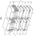
- FIG. 1 is a perspective view showing the secondary battery module according to the first embodiment.
- the secondary battery module 1 of the present embodiment mainly includes a plurality of battery cells 10 stacked on each other, and a first stacked body 11 and a second stacked body 11 arranged in a direction orthogonal to the stacking direction of the battery cells 10. It comprises a two-layered body 12 and a holding body 20 for holding the arranged first and second stacked bodies 11 and 12.
- Each of the first stacked body 11 and the second stacked body 12 includes a plurality of (here, six) flat rectangular battery cells 10 arranged according to a predetermined rule, and a double-sided protrusion between adjacent battery cells 10. They are laminated with an insulating plate 18 interposed and one-sided protruding insulating plates 19 arranged at both ends in the laminating direction.
- FIG. 2 is a perspective view showing a battery cell.
- the battery cell 10 is a flat secondary battery, and includes a battery can 13 and a battery cover 14.
- the battery can 13 has a so-called square cylindrical shape with a bottom. It has a surface portion 13b and a pair of narrow surface portions 13c having relatively small areas and facing each other. Inside the battery can 13, for example, an electrode group and an electrolytic solution wound in a flat shape are accommodated.
- the battery lid 14 is arranged at a position facing the bottom of the can, and is joined to the battery can 13 so as to close the opening of the battery can 13.
- a joining method laser welding or the like can be given.
- the battery cover 14 is also a narrow surface portion, and the battery cover 14 is provided with a positive electrode terminal 15 and a negative electrode terminal 16.
- the positive electrode terminal 15 and the negative electrode terminal 16 are connected to the positive electrode side bus bar 31, the inter-cell bus bar 32, the negative electrode side bus bar 33, or the laminated body bus bar 30 (described later) by laser welding, respectively.
- the end is formed in a planar shape.
- a liquid injection plug 17 for closing the liquid injection hole for the electrolyte is provided on the battery lid 14 on the side near the negative electrode terminal 16.
- the filling plug 17 is joined to the battery cover 14 by laser welding, for example, after filling the inside of the battery cell 10 with an electrolytic solution through a filling port.
- FIG. 3 is an exploded perspective view showing the first laminate and the second laminate. Since the first stacked body 11 and the second stacked body 12 have the same structure, an example of the first stacked body 11 will be described here. As shown in FIG. 3, the first stacked body 11 is configured by stacking six battery cells 10 in a state where the wide surface portions 13b face each other. The six battery cells 10 are connected in two parallels and two series.
- the two battery cells 10 are stacked such that the positive electrode terminal 15 of one battery cell 10 and the positive electrode terminal 15 of the other battery cell 10 are adjacent to each other in the stacking direction.
- the first stacked body 11 includes three such cell blocks (a lower cell block, an intermediate cell block, and an upper cell block arranged in order in the stacking direction in FIG. 1).
- the positive terminal group (ie, two positive terminals 15) of one adjacent cell block and the negative terminal group (ie, two negative terminals 16) of the other cell block are arranged in the stacking direction.
- the layers are alternately turned 180 ° so as to be adjacent to each other.
- a double-sided projection insulating plate 18 having a projection 18a is interposed between adjacent battery cells 10.
- a single-sided projection insulating plate 19 having a projection 19a is arranged outside the battery cell 10 positioned outermost in the stacking direction.
- the double-sided projection insulating plate 18 and the single-sided projection insulating plate 19 are formed of a resin material such as PBT (polybutylene terephthalate).
- the positive terminals 15 of the lower cell block are connected in parallel by a positive end bus bar 31.
- the negative electrode terminals 16 of the lower cell block are connected in parallel by the inter-cell bus bar 32 and further connected in series to the positive electrode terminals 15 of the adjacent intermediate cell block by the inter-cell bus bar 32. That is, the inter-cell bus bar 32 connects the negative terminals 16 of the lower cell block and the positive terminals 15 of the intermediate cell block in parallel with each other, and further connects these terminals in series.
- the negative electrode terminals 16 of the intermediate cell block are connected in parallel by the inter-cell bus bar 32, and further connected in series with the positive electrode terminals 15 of the adjacent upper cell block by the inter-cell bus bar 32.
- the negative electrode terminals 16 of the upper cell block are connected in parallel by the inter-laminate bus bar 30 (described later), and further connected to the positive electrode terminal 15 of the upper cell block of the second laminate 12 by the inter-laminate bus bar 30. They are connected in series.
- the positive-electrode-side end busbar 31 corresponds to the “busbar in the laminate” described in the claims.
- the positive-side end bus bar 31 is formed in a plate shape from, for example, a nickel material, and is mounted on these terminals so as to cover the adjacent positive terminals 15 by laser welding or screwing. It is joined with the terminal.
- the positive-side end bus bar 31 includes a convex vibration absorbing portion 31 a located between adjacent positive-electrode terminals 15, a projecting outside of the secondary battery module 1, and a module external connection terminal.
- the vibration absorbing portion 31a has a substantially U-shaped cross section, and extends in the direction in which the secondary battery module 1 and the second stacked body 12 are arranged.
- the inter-cell busbar 32 corresponds to the “busbar in the laminate” described in the claims.
- the inter-cell bus bar 32 is formed in a flat plate shape from, for example, a nickel material, and is placed on the adjacent positive electrode terminals 15 and negative electrode terminals 16 so as to cover the adjacent terminals. And these terminals are joined. As shown in FIG. 1, in the inter-cell bus bar 32, one between each of the adjacent positive terminals 15, between each of the adjacent negative terminals 16, and between each of the adjacent positive and negative terminals 15 and 16.
- Each of the convex vibration absorbing portions 32a is disposed.
- Each of the vibration absorbing portions 32a has a substantially U-shaped cross section, and extends in the arrangement direction of the secondary battery module 1 and the second stacked body 12.
- the second stacked body 12 further includes a negative electrode side end bus bar 33 in addition to the inter-cell bus bars 32, similarly to the first stacked body 11. As shown in FIG. 1, the negative electrode side end bus bar 33 connects the negative electrode terminals 16 of the lower cell block in the second stacked body 12 to each other in parallel.
- the negative-electrode-side end busbar 33 corresponds to the “busbar in the laminate” described in the claims, and includes a convex vibration absorbing portion 33a located between adjacent negative terminals 16 and a secondary A projecting portion 33b that extends outside the battery module 1 and functions as a module external connection terminal.
- the vibration absorbing portion 33a has a substantially U-shaped cross section, and extends in the direction in which the secondary battery module 1 and the second stacked body 12 are arranged.
- the sandwiching body 20 includes a pair of side plates 21 arranged on both sides in the arrangement direction of the first stacked body 11 and the second stacked body 12, and a pair of end plates arranged on both sides in the stacking direction of the battery cells 10. It has a plate 22 and a center plate 23 disposed between the pair of side plates 21 so as to partition the first stacked body 11 and the second stacked body 12.
- the side plate 21, the end plate 22, and the center plate 23 are formed of, for example, a metal material, and are fixed to each other by a plurality of screws 24.
- FIG. 4 is a perspective view showing a bus bar between laminated bodies.
- the inter-laminate bus bar 30 is formed in a plate shape from, for example, a nickel material, is bridged between the first laminate 11 and the second laminate 12, and is connected to the upper cell block of the first laminate 11 and the second cell block.
- the upper cell block of the stacked body 12 is electrically connected.
- the inter-laminate bus bar 30 is disposed on the first laminate 11 side, and has a convex first vibration absorbing portion 301 extending in the direction in which the first laminate 11 and the second laminate 12 are arranged; Between the first vibration absorber 301 and the second vibration absorber 302, which is disposed on the side of the second vibration absorber 12 and extends in the direction in which the first laminate 11 and the second laminate 12 are arranged. And a dividing portion 303 arranged at the same position.
- the first vibration absorbing portion 301 has a substantially U-shaped cross section, and is formed on the first stacked body 11 side of the inter-stacked bus bar 30 so as to be located between the adjacent negative electrode terminals 16.
- the second vibration absorbing portion 302 has a substantially U-shaped cross section, and is formed on the second stacked body 12 side of the inter-stacked bus bar 30 so as to be located between the adjacent positive electrode terminals 15.
- the first vibration absorber 301 and the second vibration absorber 302 are arranged coaxially, but may be arranged so as to be shifted from each other (that is, offset).
- first vibration absorbing portion 301 and the second vibration absorbing portion 302 may have the same length in the arrangement direction, the protrusion height, the width in the stacking direction, and the like, or may have different lengths. Further, the first vibration absorbing section 301 and the second vibration absorbing section 302 do not necessarily have to have a substantially U-shaped cross section, but may have a V-shaped cross section or a rectangular cross section.
- the dividing part 303 is a flat part formed between the first vibration absorbing part 301 and the second vibration absorbing part 302.
- through holes 304 are provided on both sides of the first vibration absorbing section 301 with the first vibration absorbing section 301 interposed therebetween, and on both sides of the second vibration absorbing section 302 with the second vibration absorbing section 302 interposed therebetween.
- the through-hole 304 functions as an insertion hole for a joining screw or a positioning hole at the time of laser welding when the inter-layer body bus bar 30 is joined to the positive electrode terminal 15 or the negative electrode terminal 16.
- the inter-laminate bus bar 30 is disposed on the first laminate 11 side and has a convex shape extending in the arrangement direction of the first laminate 11 and the second laminate 12.
- And a dividing section 303 Therefore, a load such as vibration or impact in the stacking direction of the battery cells 10 and a load resulting from expansion and contraction of the battery cells 10 are absorbed through the first vibration absorbing portions 301 and the second vibration absorbing portions 302 extending in the arrangement direction. be able to.
- the dividing portion 303 disposed between the first vibration absorbing portion 301 and the second vibration absorbing portion 302 causes a load such as a vibration or an impact in the arrangement direction of the first laminated body 11 and the second laminated body 12, The load caused by the twist between the first stacked body 11 and the second stacked body 12 can be absorbed.
- connection portion between the inter-laminate bus bar 30 and the positive electrode terminal 15 that is, a joint portion between the inter-laminate bus bar 30 and the positive electrode terminal 15
- a connection portion between the inter-laminate bus bar 30 and the negative electrode terminal 16 that is, the connection portion
- the load on the inter-laminate bus bar 30 and the negative electrode terminal 16 can be reduced, and the connection reliability between the inter-laminate bus bar 30 and the positive electrode terminal 15 or the negative electrode terminal 16 can be improved.
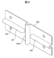
- FIG. 5 is a perspective view showing the inter-stack busbar of the secondary battery module according to the second embodiment.
- the secondary battery module of the present embodiment is different from the above-described first embodiment in the shape of the bus bar between the stacked bodies. In the following description, only the differences will be described.
- the dividing portion 303A of the inter-stack bus bar 30A is a convex vibration absorbing portion extending from one end to the other end in the stacking direction of the battery cells 10.
- the dividing portion 303A has a substantially U-shaped cross section, and is disposed between the first vibration absorbing portion 301 and the second vibration absorbing portion 302 so as to cross the inter-laminate bus bar 30A.
- the secondary battery module including the inter-stacked bus bar 30A the same operation and effect as those of the first embodiment can be obtained, and the dividing section 303A is a convex vibration absorbing section.
- the effect of absorbing a load such as vibration or impact in the arrangement direction and a load resulting from the twist between the first stacked body 11 and the second stacked body 12 can be further enhanced.
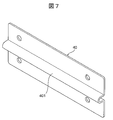
- FIG. 6 is a perspective view showing the inter-stack busbar of the secondary battery module according to the third embodiment.
- the secondary battery module of the present embodiment is different from the above-described first embodiment in the shape of the bus bar between the stacked bodies. In the following description, only the differences will be described.
- the dividing portion 303B of the inter-laminate bus bar 30B is a hole penetrating the inter-laminate bus bar 30B.
- the dividing section 303B is arranged between the first vibration absorbing section 301 and the second vibration absorbing section 302 so as to divide the communicating first vibration absorbing section 301 and second vibration absorbing section 302.
- the same operation and effect as in the first embodiment can be obtained, and the dividing portion 303B is a hole penetrating the inter-laminate bus bar 30B.
- the dividing portion 303B is a hole penetrating the inter-laminate bus bar 30B.
- the material used for the inter-busbar 30B can be reduced.
- the inter-laminate bus bar 30, the positive-side end bus bar 31, the inter-cell bus bar 32, and the negative-side end bus bar 33 are formed of a nickel material. It may be formed of a metal material or a metal composite material.
Landscapes
- Chemical & Material Sciences (AREA)
- Chemical Kinetics & Catalysis (AREA)
- Electrochemistry (AREA)
- General Chemical & Material Sciences (AREA)
- Connection Of Batteries Or Terminals (AREA)
- Battery Mounting, Suspending (AREA)
Abstract
La présente invention concerne un module d'accumulateurs (1) qui comporte : des premier et deuxième stratifiés (11, 12) qui sont formés chacun en stratifiant une pluralité d'éléments de batteries (10) et qui sont arrangés orthogonalement à la direction de stratification ; et une barre omnibus interstratifiés (30) qui est disposée entre les premier et deuxième stratifiés (11, 12) et qui connecte électriquement les éléments de batteries (10) de ces stratifiés. La barre omnibus interstratifiés (30) a une première partie d'absorption de vibrations (301) en saillie qui est disposée du côté du premier stratifié (11) afin de s'étendre dans la direction d'arrangement des premier et deuxième stratifiés (11, 12), une deuxième partie d'absorption de vibrations (302) en saillie qui est disposée du côté du deuxième stratifié (12) afin de s'étendre dans la direction d'arrangement, et une partie de division (303) qui est disposée entre les première et deuxième parties d'absorption de vibrations (301, 302).
Priority Applications (1)
| Application Number | Priority Date | Filing Date | Title |
|---|---|---|---|
| JP2020528686A JP6952195B2 (ja) | 2018-07-06 | 2019-03-01 | 二次電池モジュール |
Applications Claiming Priority (2)
| Application Number | Priority Date | Filing Date | Title |
|---|---|---|---|
| JP2018129065 | 2018-07-06 | ||
| JP2018-129065 | 2018-07-06 |
Publications (1)
| Publication Number | Publication Date |
|---|---|
| WO2020008681A1 true WO2020008681A1 (fr) | 2020-01-09 |
Family
ID=69059572
Family Applications (1)
| Application Number | Title | Priority Date | Filing Date |
|---|---|---|---|
| PCT/JP2019/008233 Ceased WO2020008681A1 (fr) | 2018-07-06 | 2019-03-01 | Module d'accumulateurs |
Country Status (2)
| Country | Link |
|---|---|
| JP (1) | JP6952195B2 (fr) |
| WO (1) | WO2020008681A1 (fr) |
Cited By (3)
| Publication number | Priority date | Publication date | Assignee | Title |
|---|---|---|---|---|
| JPWO2022024740A1 (fr) * | 2020-07-27 | 2022-02-03 | ||
| JP2024021232A (ja) * | 2022-08-03 | 2024-02-16 | プライムプラネットエナジー&ソリューションズ株式会社 | 電池モジュールおよび電池 |
| WO2024180950A1 (fr) * | 2023-02-28 | 2024-09-06 | 株式会社Gsユアサ | Dispositif de stockage d'énergie |
Citations (5)
| Publication number | Priority date | Publication date | Assignee | Title |
|---|---|---|---|---|
| JP2008251352A (ja) * | 2007-03-30 | 2008-10-16 | Mitsubishi Heavy Ind Ltd | 電池モジュール |
| JP2011065794A (ja) * | 2009-09-16 | 2011-03-31 | Toshiba Corp | 二次電池モジュール |
| JP2012079710A (ja) * | 2012-01-24 | 2012-04-19 | Auto Network Gijutsu Kenkyusho:Kk | バッテリ出力端子と端子金具の接続構造 |
| JP5976811B2 (ja) * | 2012-08-01 | 2016-08-24 | 株式会社東芝 | 二次電池の接続構造およびこれを備えた二次電池装置 |
| JP2017168340A (ja) * | 2016-03-17 | 2017-09-21 | パナソニックIpマネジメント株式会社 | 溶接構造体とそれを用いた電池および溶接構造体の製造方法 |
-
2019
- 2019-03-01 WO PCT/JP2019/008233 patent/WO2020008681A1/fr not_active Ceased
- 2019-03-01 JP JP2020528686A patent/JP6952195B2/ja active Active
Patent Citations (5)
| Publication number | Priority date | Publication date | Assignee | Title |
|---|---|---|---|---|
| JP2008251352A (ja) * | 2007-03-30 | 2008-10-16 | Mitsubishi Heavy Ind Ltd | 電池モジュール |
| JP2011065794A (ja) * | 2009-09-16 | 2011-03-31 | Toshiba Corp | 二次電池モジュール |
| JP2012079710A (ja) * | 2012-01-24 | 2012-04-19 | Auto Network Gijutsu Kenkyusho:Kk | バッテリ出力端子と端子金具の接続構造 |
| JP5976811B2 (ja) * | 2012-08-01 | 2016-08-24 | 株式会社東芝 | 二次電池の接続構造およびこれを備えた二次電池装置 |
| JP2017168340A (ja) * | 2016-03-17 | 2017-09-21 | パナソニックIpマネジメント株式会社 | 溶接構造体とそれを用いた電池および溶接構造体の製造方法 |
Cited By (7)
| Publication number | Priority date | Publication date | Assignee | Title |
|---|---|---|---|---|
| JPWO2022024740A1 (fr) * | 2020-07-27 | 2022-02-03 | ||
| WO2022024740A1 (fr) * | 2020-07-27 | 2022-02-03 | 株式会社村田製作所 | Système d'alimentation électrique et structure pour connecter une borne de connexion et une barre omnibus |
| JP7260066B2 (ja) | 2020-07-27 | 2023-04-18 | 株式会社村田製作所 | 電源システム、および、接続端子とバスバーとの接続構造 |
| US12388158B2 (en) | 2020-07-27 | 2025-08-12 | Murata Manufacturing Co., Ltd. | Power supply system and connection structure between connection terminal and busbar |
| JP2024021232A (ja) * | 2022-08-03 | 2024-02-16 | プライムプラネットエナジー&ソリューションズ株式会社 | 電池モジュールおよび電池 |
| JP7565981B2 (ja) | 2022-08-03 | 2024-10-11 | プライムプラネットエナジー&ソリューションズ株式会社 | 電池モジュールおよび電池 |
| WO2024180950A1 (fr) * | 2023-02-28 | 2024-09-06 | 株式会社Gsユアサ | Dispositif de stockage d'énergie |
Also Published As
| Publication number | Publication date |
|---|---|
| JP6952195B2 (ja) | 2021-10-20 |
| JPWO2020008681A1 (ja) | 2021-03-11 |
Similar Documents
| Publication | Publication Date | Title |
|---|---|---|
| EP3151307B1 (fr) | Module de batterie et bloc-batterie le comprenant | |
| KR101053208B1 (ko) | 용접 신뢰성이 향상된 전지모듈 및 이를 포함하는 중대형 전지팩 | |
| US11909062B2 (en) | Battery pack comprising battery pack frame capable of preventing welding defect and pressing jig for preparing the same | |
| KR101509474B1 (ko) | 단일 전극단자 결합부를 가진 전지 조합체 | |
| KR101305218B1 (ko) | 중공 구조의 고정부재와 결합 부재를 포함하는 전지모듈 및 이를 포함하는 전지팩 | |
| KR102170472B1 (ko) | 다중공동 배터리 모듈 | |
| EP2988344A1 (fr) | Module de batterie ayant une nouvelle structure et bloc batterie le comprenant | |
| US20210143505A1 (en) | Energy storage apparatus | |
| JP5160425B2 (ja) | 電池モジュールの製作に適した電池 | |
| KR102539569B1 (ko) | 복수의 전극을 갖는 배터리전지 및 이를 포함한 배터리모듈 | |
| KR20130110943A (ko) | 신규한 구조의 전지모듈 및 이를 포함하는 전지팩 | |
| KR20220037980A (ko) | 이차 전지 | |
| JP2006338934A (ja) | 蓄電体セルのパッケージ構造 | |
| JP6952195B2 (ja) | 二次電池モジュール | |
| US20260100483A1 (en) | Cell, battery, and electric device | |
| WO2019181411A1 (fr) | Module de batterie et bloc-batterie | |
| KR20220094758A (ko) | 배터리 모듈 | |
| CN119108735A (zh) | 电池组 | |
| KR102928821B1 (ko) | 전지 모듈 및 이를 포함하는 전지팩 | |
| WO2016084273A1 (fr) | Dispositif de source d'alimentation | |
| KR20150025207A (ko) | 리튬 이차전지 및 이를 포함하는 전지팩 | |
| KR20230046782A (ko) | 친환경 자동차용 전지모듈 | |
| KR20220133021A (ko) | 전지 팩 및 이를 포함하는 디바이스 | |
| KR20200092672A (ko) | 이차 전지 및 이를 포함하는 이차 전지 모듈 | |
| US20230198074A1 (en) | Power storage device |
Legal Events
| Date | Code | Title | Description |
|---|---|---|---|
| 121 | Ep: the epo has been informed by wipo that ep was designated in this application |
Ref document number: 19830630 Country of ref document: EP Kind code of ref document: A1 |
|
| ENP | Entry into the national phase |
Ref document number: 2020528686 Country of ref document: JP Kind code of ref document: A |
|
| NENP | Non-entry into the national phase |
Ref country code: DE |
|
| 122 | Ep: pct application non-entry in european phase |
Ref document number: 19830630 Country of ref document: EP Kind code of ref document: A1 |