WO2020008681A1 - 二次電池モジュール - Google Patents
二次電池モジュール Download PDFInfo
- Publication number
- WO2020008681A1 WO2020008681A1 PCT/JP2019/008233 JP2019008233W WO2020008681A1 WO 2020008681 A1 WO2020008681 A1 WO 2020008681A1 JP 2019008233 W JP2019008233 W JP 2019008233W WO 2020008681 A1 WO2020008681 A1 WO 2020008681A1
- Authority
- WO
- WIPO (PCT)
- Prior art keywords
- laminate
- vibration absorbing
- bus bar
- stacked body
- secondary battery
- Prior art date
- Legal status (The legal status is an assumption and is not a legal conclusion. Google has not performed a legal analysis and makes no representation as to the accuracy of the status listed.)
- Ceased
Links
Images


Classifications
-
- H—ELECTRICITY
- H01—ELECTRIC ELEMENTS
- H01M—PROCESSES OR MEANS, e.g. BATTERIES, FOR THE DIRECT CONVERSION OF CHEMICAL ENERGY INTO ELECTRICAL ENERGY
- H01M50/00—Constructional details or processes of manufacture of the non-active parts of electrochemical cells other than fuel cells, e.g. hybrid cells
- H01M50/20—Mountings; Secondary casings or frames; Racks, modules or packs; Suspension devices; Shock absorbers; Transport or carrying devices; Holders
- H01M50/204—Racks, modules or packs for multiple batteries or multiple cells
- H01M50/207—Racks, modules or packs for multiple batteries or multiple cells characterised by their shape
- H01M50/209—Racks, modules or packs for multiple batteries or multiple cells characterised by their shape adapted for prismatic or rectangular cells
-
- H—ELECTRICITY
- H01—ELECTRIC ELEMENTS
- H01M—PROCESSES OR MEANS, e.g. BATTERIES, FOR THE DIRECT CONVERSION OF CHEMICAL ENERGY INTO ELECTRICAL ENERGY
- H01M50/00—Constructional details or processes of manufacture of the non-active parts of electrochemical cells other than fuel cells, e.g. hybrid cells
- H01M50/50—Current conducting connections for cells or batteries
-
- Y—GENERAL TAGGING OF NEW TECHNOLOGICAL DEVELOPMENTS; GENERAL TAGGING OF CROSS-SECTIONAL TECHNOLOGIES SPANNING OVER SEVERAL SECTIONS OF THE IPC; TECHNICAL SUBJECTS COVERED BY FORMER USPC CROSS-REFERENCE ART COLLECTIONS [XRACs] AND DIGESTS
- Y02—TECHNOLOGIES OR APPLICATIONS FOR MITIGATION OR ADAPTATION AGAINST CLIMATE CHANGE
- Y02E—REDUCTION OF GREENHOUSE GAS [GHG] EMISSIONS, RELATED TO ENERGY GENERATION, TRANSMISSION OR DISTRIBUTION
- Y02E60/00—Enabling technologies; Technologies with a potential or indirect contribution to GHG emissions mitigation
- Y02E60/10—Energy storage using batteries
Definitions
- the present invention relates to a secondary battery module, and more particularly, to a secondary battery module used for a vehicle.
- This application claims priority based on Japanese Patent Application No. 2018-129065 filed on July 6, 2018, the contents of which are incorporated herein by reference.
- aqueous batteries such as lead batteries, nickel-cadmium batteries, and nickel-hydrogen batteries have been the mainstream.
- lithium ion secondary batteries having a high energy density, and research, development, and commercialization thereof have been rapidly advanced.
- prismatic lithium-ion secondary batteries have excellent volumetric efficiency when modularized (also referred to as packs), and have begun to be deployed in automotive applications for HEVs (hybrid vehicles) or EVs (electric vehicles). I have.
- Patent Document 1 discloses a structure in which a bus bar that electrically connects terminals of adjacent battery cells is provided with a vibration-absorbing portion that is convexly curved.
- Patent Literature 2 discloses a secondary battery module provided with a bus bar that connects a plurality of battery cells in parallel.
- the load such as vibration and impact in the stacking direction of the battery cells and the load due to the expansion and contraction of the battery cells can be absorbed by the vibration absorbing portion. It is difficult to cope with loads such as vibrations and shocks in the arrangement direction of the bodies, loads caused by torsion between the stacked bodies, and the like. For this reason, the load concentrates on the connection part between the inter-stack bus bar and the battery cell, and the connection part may be damaged. Therefore, there is a problem that the connection reliability between the inter-stack bus bar and the battery cell is impaired.
- the present invention has been made in order to solve such a technical problem, and reduces a load on a connection portion between a stacked body bus bar and a battery cell, and reduces a connection reliability between the stacked body bus bar and a battery cell. It is an object of the present invention to provide a secondary battery module capable of improving performance.
- the secondary battery module includes a first stacked body and a second stacked body each formed by stacking a plurality of battery cells and arranged along a direction orthogonal to a stacking direction of the battery cells, A stacked body that is bridged between a first stacked body and the second stacked body and electrically connects the plurality of battery cells of the first stacked body and the plurality of battery cells of the second stacked body.
- a bus bar wherein the inter-laminate bus bar is disposed on the first laminate side, and has a convex first vibration absorbing portion extending in an arrangement direction of the first laminate and the second laminate.
- a convex second vibration absorber arranged on the side of the second laminate and extending in an arrangement direction of the first laminate and the second laminate, the first vibration absorber and the second vibration absorber; And a dividing part disposed between the two.
- the inter-laminate bus bar is disposed on the first laminate side and extends in the direction in which the first laminate and the second laminate are arranged.
- a convex second vibration absorbing portion that is arranged and extends in the arrangement direction of the first laminate and the second laminate, and a dividing portion that is disposed between the first vibration absorbing portion and the second vibration absorbing portion. Accordingly, the load on the connection between the inter-laminate bus bar and the battery cell can be reduced, and the connection reliability between the inter-laminate bus bar and the battery cell can be improved.
- FIG. 2 is a perspective view showing the secondary battery module according to the first embodiment. It is a perspective view which shows a battery cell.
- FIG. 3 is an exploded perspective view showing a first stacked body and a second stacked body. It is a perspective view which shows the bus bar between laminated bodies. It is a perspective view which shows the bus bar between laminated bodies of the secondary battery module which concerns on 2nd Embodiment. It is a perspective view which shows the bus bar between laminated bodies of the secondary battery module which concerns on 3rd Embodiment. It is a perspective view which shows the conventional bus bar between laminated bodies.
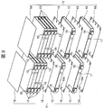
- FIG. 1 is a perspective view showing the secondary battery module according to the first embodiment.
- the secondary battery module 1 of the present embodiment mainly includes a plurality of battery cells 10 stacked on each other, and a first stacked body 11 and a second stacked body 11 arranged in a direction orthogonal to the stacking direction of the battery cells 10. It comprises a two-layered body 12 and a holding body 20 for holding the arranged first and second stacked bodies 11 and 12.
- Each of the first stacked body 11 and the second stacked body 12 includes a plurality of (here, six) flat rectangular battery cells 10 arranged according to a predetermined rule, and a double-sided protrusion between adjacent battery cells 10. They are laminated with an insulating plate 18 interposed and one-sided protruding insulating plates 19 arranged at both ends in the laminating direction.
- FIG. 2 is a perspective view showing a battery cell.
- the battery cell 10 is a flat secondary battery, and includes a battery can 13 and a battery cover 14.
- the battery can 13 has a so-called square cylindrical shape with a bottom. It has a surface portion 13b and a pair of narrow surface portions 13c having relatively small areas and facing each other. Inside the battery can 13, for example, an electrode group and an electrolytic solution wound in a flat shape are accommodated.
- the battery lid 14 is arranged at a position facing the bottom of the can, and is joined to the battery can 13 so as to close the opening of the battery can 13.
- a joining method laser welding or the like can be given.
- the battery cover 14 is also a narrow surface portion, and the battery cover 14 is provided with a positive electrode terminal 15 and a negative electrode terminal 16.
- the positive electrode terminal 15 and the negative electrode terminal 16 are connected to the positive electrode side bus bar 31, the inter-cell bus bar 32, the negative electrode side bus bar 33, or the laminated body bus bar 30 (described later) by laser welding, respectively.
- the end is formed in a planar shape.
- a liquid injection plug 17 for closing the liquid injection hole for the electrolyte is provided on the battery lid 14 on the side near the negative electrode terminal 16.
- the filling plug 17 is joined to the battery cover 14 by laser welding, for example, after filling the inside of the battery cell 10 with an electrolytic solution through a filling port.
- FIG. 3 is an exploded perspective view showing the first laminate and the second laminate. Since the first stacked body 11 and the second stacked body 12 have the same structure, an example of the first stacked body 11 will be described here. As shown in FIG. 3, the first stacked body 11 is configured by stacking six battery cells 10 in a state where the wide surface portions 13b face each other. The six battery cells 10 are connected in two parallels and two series.
- the two battery cells 10 are stacked such that the positive electrode terminal 15 of one battery cell 10 and the positive electrode terminal 15 of the other battery cell 10 are adjacent to each other in the stacking direction.
- the first stacked body 11 includes three such cell blocks (a lower cell block, an intermediate cell block, and an upper cell block arranged in order in the stacking direction in FIG. 1).
- the positive terminal group (ie, two positive terminals 15) of one adjacent cell block and the negative terminal group (ie, two negative terminals 16) of the other cell block are arranged in the stacking direction.
- the layers are alternately turned 180 ° so as to be adjacent to each other.
- a double-sided projection insulating plate 18 having a projection 18a is interposed between adjacent battery cells 10.
- a single-sided projection insulating plate 19 having a projection 19a is arranged outside the battery cell 10 positioned outermost in the stacking direction.
- the double-sided projection insulating plate 18 and the single-sided projection insulating plate 19 are formed of a resin material such as PBT (polybutylene terephthalate).
- the positive terminals 15 of the lower cell block are connected in parallel by a positive end bus bar 31.
- the negative electrode terminals 16 of the lower cell block are connected in parallel by the inter-cell bus bar 32 and further connected in series to the positive electrode terminals 15 of the adjacent intermediate cell block by the inter-cell bus bar 32. That is, the inter-cell bus bar 32 connects the negative terminals 16 of the lower cell block and the positive terminals 15 of the intermediate cell block in parallel with each other, and further connects these terminals in series.
- the negative electrode terminals 16 of the intermediate cell block are connected in parallel by the inter-cell bus bar 32, and further connected in series with the positive electrode terminals 15 of the adjacent upper cell block by the inter-cell bus bar 32.
- the negative electrode terminals 16 of the upper cell block are connected in parallel by the inter-laminate bus bar 30 (described later), and further connected to the positive electrode terminal 15 of the upper cell block of the second laminate 12 by the inter-laminate bus bar 30. They are connected in series.
- the positive-electrode-side end busbar 31 corresponds to the “busbar in the laminate” described in the claims.
- the positive-side end bus bar 31 is formed in a plate shape from, for example, a nickel material, and is mounted on these terminals so as to cover the adjacent positive terminals 15 by laser welding or screwing. It is joined with the terminal.
- the positive-side end bus bar 31 includes a convex vibration absorbing portion 31 a located between adjacent positive-electrode terminals 15, a projecting outside of the secondary battery module 1, and a module external connection terminal.
- the vibration absorbing portion 31a has a substantially U-shaped cross section, and extends in the direction in which the secondary battery module 1 and the second stacked body 12 are arranged.
- the inter-cell busbar 32 corresponds to the “busbar in the laminate” described in the claims.
- the inter-cell bus bar 32 is formed in a flat plate shape from, for example, a nickel material, and is placed on the adjacent positive electrode terminals 15 and negative electrode terminals 16 so as to cover the adjacent terminals. And these terminals are joined. As shown in FIG. 1, in the inter-cell bus bar 32, one between each of the adjacent positive terminals 15, between each of the adjacent negative terminals 16, and between each of the adjacent positive and negative terminals 15 and 16.
- Each of the convex vibration absorbing portions 32a is disposed.
- Each of the vibration absorbing portions 32a has a substantially U-shaped cross section, and extends in the arrangement direction of the secondary battery module 1 and the second stacked body 12.
- the second stacked body 12 further includes a negative electrode side end bus bar 33 in addition to the inter-cell bus bars 32, similarly to the first stacked body 11. As shown in FIG. 1, the negative electrode side end bus bar 33 connects the negative electrode terminals 16 of the lower cell block in the second stacked body 12 to each other in parallel.
- the negative-electrode-side end busbar 33 corresponds to the “busbar in the laminate” described in the claims, and includes a convex vibration absorbing portion 33a located between adjacent negative terminals 16 and a secondary A projecting portion 33b that extends outside the battery module 1 and functions as a module external connection terminal.
- the vibration absorbing portion 33a has a substantially U-shaped cross section, and extends in the direction in which the secondary battery module 1 and the second stacked body 12 are arranged.
- the sandwiching body 20 includes a pair of side plates 21 arranged on both sides in the arrangement direction of the first stacked body 11 and the second stacked body 12, and a pair of end plates arranged on both sides in the stacking direction of the battery cells 10. It has a plate 22 and a center plate 23 disposed between the pair of side plates 21 so as to partition the first stacked body 11 and the second stacked body 12.
- the side plate 21, the end plate 22, and the center plate 23 are formed of, for example, a metal material, and are fixed to each other by a plurality of screws 24.
- FIG. 4 is a perspective view showing a bus bar between laminated bodies.
- the inter-laminate bus bar 30 is formed in a plate shape from, for example, a nickel material, is bridged between the first laminate 11 and the second laminate 12, and is connected to the upper cell block of the first laminate 11 and the second cell block.
- the upper cell block of the stacked body 12 is electrically connected.
- the inter-laminate bus bar 30 is disposed on the first laminate 11 side, and has a convex first vibration absorbing portion 301 extending in the direction in which the first laminate 11 and the second laminate 12 are arranged; Between the first vibration absorber 301 and the second vibration absorber 302, which is disposed on the side of the second vibration absorber 12 and extends in the direction in which the first laminate 11 and the second laminate 12 are arranged. And a dividing portion 303 arranged at the same position.
- the first vibration absorbing portion 301 has a substantially U-shaped cross section, and is formed on the first stacked body 11 side of the inter-stacked bus bar 30 so as to be located between the adjacent negative electrode terminals 16.
- the second vibration absorbing portion 302 has a substantially U-shaped cross section, and is formed on the second stacked body 12 side of the inter-stacked bus bar 30 so as to be located between the adjacent positive electrode terminals 15.
- the first vibration absorber 301 and the second vibration absorber 302 are arranged coaxially, but may be arranged so as to be shifted from each other (that is, offset).
- first vibration absorbing portion 301 and the second vibration absorbing portion 302 may have the same length in the arrangement direction, the protrusion height, the width in the stacking direction, and the like, or may have different lengths. Further, the first vibration absorbing section 301 and the second vibration absorbing section 302 do not necessarily have to have a substantially U-shaped cross section, but may have a V-shaped cross section or a rectangular cross section.
- the dividing part 303 is a flat part formed between the first vibration absorbing part 301 and the second vibration absorbing part 302.
- through holes 304 are provided on both sides of the first vibration absorbing section 301 with the first vibration absorbing section 301 interposed therebetween, and on both sides of the second vibration absorbing section 302 with the second vibration absorbing section 302 interposed therebetween.
- the through-hole 304 functions as an insertion hole for a joining screw or a positioning hole at the time of laser welding when the inter-layer body bus bar 30 is joined to the positive electrode terminal 15 or the negative electrode terminal 16.
- the inter-laminate bus bar 30 is disposed on the first laminate 11 side and has a convex shape extending in the arrangement direction of the first laminate 11 and the second laminate 12.
- And a dividing section 303 Therefore, a load such as vibration or impact in the stacking direction of the battery cells 10 and a load resulting from expansion and contraction of the battery cells 10 are absorbed through the first vibration absorbing portions 301 and the second vibration absorbing portions 302 extending in the arrangement direction. be able to.
- the dividing portion 303 disposed between the first vibration absorbing portion 301 and the second vibration absorbing portion 302 causes a load such as a vibration or an impact in the arrangement direction of the first laminated body 11 and the second laminated body 12, The load caused by the twist between the first stacked body 11 and the second stacked body 12 can be absorbed.
- connection portion between the inter-laminate bus bar 30 and the positive electrode terminal 15 that is, a joint portion between the inter-laminate bus bar 30 and the positive electrode terminal 15
- a connection portion between the inter-laminate bus bar 30 and the negative electrode terminal 16 that is, the connection portion
- the load on the inter-laminate bus bar 30 and the negative electrode terminal 16 can be reduced, and the connection reliability between the inter-laminate bus bar 30 and the positive electrode terminal 15 or the negative electrode terminal 16 can be improved.
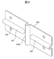
- FIG. 5 is a perspective view showing the inter-stack busbar of the secondary battery module according to the second embodiment.
- the secondary battery module of the present embodiment is different from the above-described first embodiment in the shape of the bus bar between the stacked bodies. In the following description, only the differences will be described.
- the dividing portion 303A of the inter-stack bus bar 30A is a convex vibration absorbing portion extending from one end to the other end in the stacking direction of the battery cells 10.
- the dividing portion 303A has a substantially U-shaped cross section, and is disposed between the first vibration absorbing portion 301 and the second vibration absorbing portion 302 so as to cross the inter-laminate bus bar 30A.
- the secondary battery module including the inter-stacked bus bar 30A the same operation and effect as those of the first embodiment can be obtained, and the dividing section 303A is a convex vibration absorbing section.
- the effect of absorbing a load such as vibration or impact in the arrangement direction and a load resulting from the twist between the first stacked body 11 and the second stacked body 12 can be further enhanced.
- FIG. 6 is a perspective view showing the inter-stack busbar of the secondary battery module according to the third embodiment.
- the secondary battery module of the present embodiment is different from the above-described first embodiment in the shape of the bus bar between the stacked bodies. In the following description, only the differences will be described.
- the dividing portion 303B of the inter-laminate bus bar 30B is a hole penetrating the inter-laminate bus bar 30B.
- the dividing section 303B is arranged between the first vibration absorbing section 301 and the second vibration absorbing section 302 so as to divide the communicating first vibration absorbing section 301 and second vibration absorbing section 302.
- the same operation and effect as in the first embodiment can be obtained, and the dividing portion 303B is a hole penetrating the inter-laminate bus bar 30B.
- the dividing portion 303B is a hole penetrating the inter-laminate bus bar 30B.
- the material used for the inter-busbar 30B can be reduced.
- the inter-laminate bus bar 30, the positive-side end bus bar 31, the inter-cell bus bar 32, and the negative-side end bus bar 33 are formed of a nickel material. It may be formed of a metal material or a metal composite material.
Landscapes
- Chemical & Material Sciences (AREA)
- Chemical Kinetics & Catalysis (AREA)
- Electrochemistry (AREA)
- General Chemical & Material Sciences (AREA)
- Connection Of Batteries Or Terminals (AREA)
- Battery Mounting, Suspending (AREA)
Abstract
二次電池モジュール1は、複数の電池セル10を積層してなるとともに積層方向と直交する方向に配列される第1積層体11と第2積層体12と、第1積層体11と第2積層体12との間に架け渡され、これらの積層体の電池セル10同士を電気的に接続する積層体間バスバー30とを備える。積層体間バスバー30は、第1積層体11側に配置され、第1積層体11と第2積層体12との配列方向に延びる凸状の第1振動吸収部301と、第2積層体12側に配置されて配列方向に延びる凸状の第2振動吸収部302と、第1振動吸収部301と第2振動吸収部302との間に配置される分断部303とを有する。
Description
本発明は、二次電池モジュールに関し、特に車載用途に使用される二次電池モジュールに関する。
本願は、2018年7月6日に出願された日本国特願2018-129065号に基づき優先権を主張し、その内容をここに援用する。
本願は、2018年7月6日に出願された日本国特願2018-129065号に基づき優先権を主張し、その内容をここに援用する。
従来、再充電可能な二次電池の分野では、鉛電池、ニッケル-カドミウム電池、ニッケル-水素電池等の水溶液系電池が主流であった。しかしながら、電気機器の小型化、軽量化が進むにつれ、高エネルギー密度を有するリチウムイオン二次電池が着目され、その研究、開発及び商品化が急速に進められた。特に角形リチウムイオン二次電池は、モジュール化(パック化ともいう)した際の体積効率が優れているため、HEV(ハイブリッド車)用あるいはEV(電気自動車)用として車載用途への展開も始まっている。
車両では、振動や衝撃等の負荷が二次電池モジュールに加わる場合がある。また、二次電池モジュールを構成する電池セルでは、膨張や収縮によって変形が発生し、これに起因して二次電池モジュールに負荷がかかる場合もある。これらの負荷で壊れにくい構造として、下記特許文献1では、隣接する電池セルの端子同士を電気的に接続するバスバーに凸状に湾曲した振動吸収部を設ける構造が開示されている。また、リチウムイオン二次電池に対する要求性能は年々高まっており、大電流化及び高容量化の要求に対応するため、電池セルを並列に接続したものも検討されている。下記特許文献2では、複数の電池セルを並列に接続するバスバーが設けられた二次電池モジュールが開示されている。
上記特許文献2で開示されている二次電池モジュールでは、複数の電池セルを積層した積層体同士を幅広いバスバーで接続する技術が示されているが、該幅広いバスバーに振動や衝撃等の負荷、電池セルの膨張収縮に起因する負荷を吸収するような構造を設けておらず、大きな振動や衝撃が加わった場合、又は電池セルが長期使用や充放電により膨張収縮した場合、バスバーと電池セルとの接続部に負荷が集中し、接続部が破損する懸念がある。
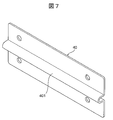
これに対して、特許文献2の幅広いバスバーに特許文献1で開示された振動吸収構造を適用することが考えられている。例えば図7に示すように、隣接する積層体同士の間に配置された積層体間バスバー40において、積層体同士の配列方向(すなわち、電池セルの積層方向と直交する方向)に沿って一端から他端まで延びる凸状の振動吸収部401を設けることにより、上述の負荷を吸収することが検討される。
しかし、このように構成された積層体間バスバーでは、電池セルの積層方向の振動や衝撃等の負荷、電池セルの膨張収縮に起因する負荷を該振動吸収部で吸収することができるが、積層体同士の配列方向の振動や衝撃等の負荷、積層体間の捩じれに起因する負荷等に対応し難い。このため、積層体間バスバーと電池セルとの接続部に負荷が集中し、接続部が破損する可能性があるので、積層体間バスバーと電池セルとの接続信頼性が損なわれる問題がある。
本発明は、このような技術課題を解決するためになされたものであって、積層体間バスバーと電池セルとの接続部への負荷を軽減し、積層体間バスバーと電池セルとの接続信頼性を向上できる二次電池モジュールを提供することを目的とする。
本発明に係る二次電池モジュールは、それぞれ複数の電池セルを積層してなるとともに、前記電池セルの積層方向と直交する方向に沿って配列される第1積層体と第2積層体と、前記第1積層体と前記第2積層体との間に架け渡され、前記第1積層体の複数の前記電池セルと前記第2積層体の複数の前記電池セルとを電気的に接続する積層体間バスバーと、を備え、前記積層体間バスバーは、前記第1積層体側に配置され、前記第1積層体と前記第2積層体との配列方向に延びる凸状の第1振動吸収部と、前記第2積層体側に配置され、前記第1積層体と前記第2積層体との配列方向に延びる凸状の第2振動吸収部と、前記第1振動吸収部と前記第2振動吸収部との間に配置される分断部と、を有することを特徴とする。
本発明によれば、積層体間バスバーが、第1積層体側に配置されて第1積層体と第2積層体との配列方向に延びる凸状の第1振動吸収部と、第2積層体側に配置されて第1積層体と第2積層体との配列方向に延びる凸状の第2振動吸収部と、第1振動吸収部と第2振動吸収部との間に配置される分断部とを有するので、積層体間バスバーと電池セルとの接続部への負荷を軽減でき、積層体間バスバーと電池セルとの接続信頼性を向上することができる。
以下、図面を参照して本発明に係る二次電池モジュールの実施形態について説明する。下記の説明において、上下等の位置は、説明が煩雑になるのを避けるために図面に従って便宜上付けたものであり、実際の使用状態での位置を指すとは限らない、また、説明の煩雑を避けるために、「電池セルの積層方向」を「積層方向」、「第1積層体と第2積層体との配列方向」を「配列方向」と省略する場合がある。
[第1実施形態]
図1は第1実施形態に係る二次電池モジュールを示す斜視図である。本実施形態の二次電池モジュール1は、主に、それぞれ複数の電池セル10を積層してなるとともに、電池セル10の積層方向と直交する方向に沿って配列される第1積層体11と第2積層体12と、配列された第1積層体11及び第2積層体12を挟持する挟持体20とを備えている。
図1は第1実施形態に係る二次電池モジュールを示す斜視図である。本実施形態の二次電池モジュール1は、主に、それぞれ複数の電池セル10を積層してなるとともに、電池セル10の積層方向と直交する方向に沿って配列される第1積層体11と第2積層体12と、配列された第1積層体11及び第2積層体12を挟持する挟持体20とを備えている。
第1積層体11及び第2積層体12は、それぞれ、複数(ここでは、6個)の扁平角形の電池セル10を所定の規則で配置するとともに、隣接する電池セル10同士の間に両面突起絶縁板18を介在させ且つ積層方向の両端に片面突起絶縁板19を配置した状態で積層されている。第1積層体11及び第2積層体12の構造を詳細に説明する前に、図2を基に電池セル10の構造を説明する。
図2は電池セルを示す斜視図である。図2に示すように、電池セル10は、扁平型の二次電池であり、電池缶13及び電池蓋14を有する。電池缶13は、いわゆる有底角筒状を呈しており、矩形状に形成された缶底部13aと、缶底部13aの四周から立ち上がるとともに相対的に面積が大きく形成されて互いに対向する一対の幅広面部13bと、相対的に面積が小さく形成されて互いに対向する一対の幅狭面部13cとを有する。電池缶13の内部には、例えば扁平状に捲回された電極群及び電解液が収容されている。
電池蓋14は、缶底部と対向する位置に配置されており、電池缶13の開口部を塞ぐように電池缶13と接合されている。接合方法として、レーザ溶接等が挙げられる。図2に示すように、電池蓋14も幅狭面部であり、該電池蓋14には正極端子15と負極端子16とが突設されている。正極端子15及び負極端子16は、レーザ溶接で正極側端部バスバー31、セル間バスバー32、負極側端部バスバー33又は積層体間バスバー30(後述する)と接合し易くするために、それぞれの端部が平面状に形成されている。
また、電池蓋14において、負極端子16寄り側には電解液の注液口を塞ぐための注液栓17が設けられている。注液栓17は、例えば注液口を介して電解液を電池セル10内部に充填した後に、レーザ溶接で電池蓋14と接合されている。
図3は第1積層体及び第2積層体を示す分解斜視図である。第1積層体11と第2積層体12とは、同じ構造を有するため、ここでは第1積層体11の例を挙げて説明する。図3に示すように、第1積層体11は、6個の電池セル10を、幅広面部13b同士を対向させた状態で積層することにより構成されている。6個の電池セル10は、2並列2直列に接続されるようになっている。
具体的には、2つの電池セル10は、一方の電池セル10の正極端子15と他方の電池セル10の正極端子15とが積層方向に隣り合うように積層されており、1つのセルブロックを構成する。従って、第1積層体11は、このようなセルブロックを3つ(図1では、積層方向に沿って順に配置された下側セルブロック、中間セルブロック及び上側セルブロック)有する。そして、3つのセルブロックは、隣接する一方のセルブロックの正極端子群(すなわち、2つの正極端子15)と他方のセルブロックの負極端子群(すなわち、2つの負極端子16)とが積層方向に隣り合うように交互に180°反転された状態で積層されている。
図3に示すように、隣接する電池セル10同士の間には、突起18aを有する両面突起絶縁板18が介在されている。また、積層方向において最も外側に位置する電池セル10の外側には、突起19aを有する片面突起絶縁板19が配置されている。両面突起絶縁板18及び片面突起絶縁板19は、例えばPBT(ポリブチレンテレフタレート)等の樹脂材料によって形成されている。
図1に示すように、第1積層体11を構成する3つのセルブロックのうち、下側セルブロックの正極端子15同士は、正極側端部バスバー31によって並列に接続されている。一方、下側セルブロックの負極端子16同士は、セル間バスバー32によって並列に接続されつつ、更に該セル間バスバー32によって隣接する中間セルブロックの正極端子15同士と直列に接続されている。すなわち、セル間バスバー32は、下側セルブロックの負極端子16同士、中間セルブロックの正極端子15同士をそれぞれ並列に接続した状態で、更にこれらの端子を直列に接続している。
同様に、中間セルブロックの負極端子16同士は、セル間バスバー32によって並列に接続されつつ、更に該セル間バスバー32によって隣接する上側セルブロックの正極端子15同士と直列に接続されている。そして、上側セルブロックの負極端子16同士は、積層体間バスバー30(後述する)によって並列に接続されつつ、更に該積層体間バスバー30によって第2積層体12の上側セルブロックの正極端子15と直列に接続されている。
正極側端部バスバー31は、特許請求の範囲に記載の「積層体内バスバー」に相当するものである。この正極側端部バスバー31は、例えばニッケル材料によって板状に形成されており、隣接する正極端子15同士を覆うようにこれらの端子の上に載せられた状態、レーザ溶接やネジ止めでこれらの端子と接合されている。図1に示すように、正極側端部バスバー31は、隣接する正極端子15同士の間に位置する凸状の振動吸収部31aと、二次電池モジュール1の外方に張り出してモジュール外部接続端子として機能する張出部31bとを有する。振動吸収部31aは、断面略U字状を呈しており、二次電池モジュール1と第2積層体12との配列方向に延びている。このように振動吸収部31aを設けることで、電池セル10の積層方向の振動や衝撃等の負荷、電池セル10の膨張収縮に起因する負荷を吸収することができる。
セル間バスバー32は、特許請求の範囲に記載の「積層体内バスバー」に相当するものである。このセル間バスバー32は、例えばニッケル材料によって平板状に形成されており、隣接する正極端子15同士及び負極端子16同士を覆うようにこれらの端子の上に載せられた状態、レーザ溶接やネジ止めでこれらの端子と接合されている。図1に示すように、セル間バスバー32において、隣接する正極端子15同士の間、隣接する負極端子16同士の間、及び隣接する正極端子15と負極端子16との間には、それぞれ1つずつの凸状の振動吸収部32aが配置されている。各振動吸収部32aは、断面略U字状を呈しており、二次電池モジュール1と第2積層体12との配列方向に延びている。
第2積層体12は、第1積層体11と同様にセル間バスバー32のほか、負極側端部バスバー33を更に備えている。図1に示すように、負極側端部バスバー33は、第2積層体12における下側セルブロックの負極端子16同士を並列に接続している。この負極側端部バスバー33は、特許請求の範囲に記載の「積層体内バスバー」に相当するものであり、隣接する負極端子16同士の間に位置する凸状の振動吸収部33aと、二次電池モジュール1の外方に張り出してモジュール外部接続端子として機能する張出部33bとを有する。振動吸収部33aは、断面略U字状を呈しており、二次電池モジュール1と第2積層体12との配列方向に延びている。
一方、挟持体20は、第1積層体11と第2積層体12との配列方向の両側に配置される一対のサイドプレート21と、電池セル10の積層方向の両側に配置される一対のエンドプレート22と、第1積層体11と第2積層体12とを仕切るように一対のサイドプレート21の間に配置されるセンタープレート23とを有する。サイドプレート21、エンドプレート22及びセンタープレート23は、例えば金属材料によって形成されており、複数のネジ24で互いに固定されている。
以下、図1に図4を加えて積層体間バスバー30の構造を説明する。図4は積層体間バスバーを示す斜視図である。積層体間バスバー30は、例えばニッケル材料によって板状に形成されており、第1積層体11と第2積層体12との間に架け渡され、第1積層体11の上側セルブロックと第2積層体12の上側セルブロックとを電気的に接続している。この積層体間バスバー30は、第1積層体11側に配置され、第1積層体11と第2積層体12との配列方向に延びる凸状の第1振動吸収部301と、第2積層体12側に配置され、第1積層体11と第2積層体12との配列方向に延びる凸状の第2振動吸収部302と、第1振動吸収部301と第2振動吸収部302との間に配置される分断部303と、を有する。
第1振動吸収部301は、断面略U字状を呈しており、隣接する負極端子16同士の間に位置するように積層体間バスバー30の第1積層体11側に形成されている。第2振動吸収部302は、断面略U字状を呈しており、隣接する正極端子15同士の間に位置するように積層体間バスバー30の第2積層体12側に形成されている。本実施形態において、第1振動吸収部301と第2振動吸収部302とは、同軸上に配置されているが、互いにずれる(すなわち、オフセットになる)ように配置されても良い。また、第1振動吸収部301及び第2振動吸収部302は、配列方向における長さ、凸出高さ、積層方向における幅等が同じであっても良く、異なっても良い。また、第1振動吸収部301及び第2振動吸収部302は、必ずしも断面略U字状を呈する必要がなく、断面V字状、断面矩形状を呈しても良い。
分断部303は、第1振動吸収部301と第2振動吸収部302との間に形成された平坦部である。
また、第1振動吸収部301を挟んで該第1振動吸収部301の両側、及び、第2振動吸収部302を挟んで該第2振動吸収部302の両側には、貫通孔304がそれぞれ設けられている。貫通孔304は、積層体間バスバー30を正極端子15又は負極端子16と接合させるときに、接合用ネジの挿入孔又はレーザ溶接時の位置決め孔として機能する。
以上の構成を有する二次電池モジュール1では、積層体間バスバー30は、第1積層体11側に配置されて第1積層体11と第2積層体12との配列方向に延びる凸状の第1振動吸収部301と、第2積層体12側に配置されて配列方向に延びる凸状の第2振動吸収部302と、第1振動吸収部301と第2振動吸収部302との間に配置される分断部303とを有する。このため、配列方向に延びる第1振動吸収部301及び第2振動吸収部302を介し、電池セル10の積層方向の振動や衝撃等の負荷、電池セル10の膨張収縮に起因する負荷を吸収することができる。
また、第1振動吸収部301と第2振動吸収部302との間に配置される分断部303によって、第1積層体11と第2積層体12との配列方向の振動や衝撃等の負荷、第1積層体11及び第2積層体12の間の捩じれに起因する負荷を吸収することができる。その結果、積層体間バスバー30と正極端子15との接続部(すなわち、積層体間バスバー30と正極端子15との接合部)、積層体間バスバー30と負極端子16との接続部(すなわち、積層体間バスバー30と負極端子16との接合部)への負荷を軽減することができ、積層体間バスバー30と正極端子15又は負極端子16との接続信頼性を向上することができる。
[第2実施形態]
図5は第2実施形態に係る二次電池モジュールの積層体間バスバーを示す斜視図である。本実施形態の二次電池モジュールは、積層体間バスバーの形状において上述の第1実施形態と相違している。以下の説明では、その相違点のみを説明する。
図5は第2実施形態に係る二次電池モジュールの積層体間バスバーを示す斜視図である。本実施形態の二次電池モジュールは、積層体間バスバーの形状において上述の第1実施形態と相違している。以下の説明では、その相違点のみを説明する。
図5に示すように、積層体間バスバー30Aの分断部303Aは、電池セル10の積層方向に沿って一端から他端まで延びる凸状の振動吸収部である。該分断部303Aは、断面略U字状を呈しており、積層体間バスバー30Aを横断するように、第1振動吸収部301と第2振動吸収部302との間に配置されている。
このような積層体間バスバー30Aを備える二次電池モジュールによれば、第1実施形態と同様な作用効果を得られるほか、分断部303Aが凸状の振動吸収部であるので、第1実施形態と比べて配列方向の振動や衝撃等の負荷、第1積層体11及び第2積層体12の間の捩じれに起因する負荷を吸収する効果を更に高めることができる。
[第3実施形態]
図6は第3実施形態に係る二次電池モジュールの積層体間バスバーを示す斜視図である。本実施形態の二次電池モジュールは、積層体間バスバーの形状において上述の第1実施形態と相違している。以下の説明では、その相違点のみを説明する。
図6は第3実施形態に係る二次電池モジュールの積層体間バスバーを示す斜視図である。本実施形態の二次電池モジュールは、積層体間バスバーの形状において上述の第1実施形態と相違している。以下の説明では、その相違点のみを説明する。
図6に示すように、積層体間バスバー30Bの分断部303Bは、該積層体間バスバー30Bを貫通する孔部である。該分断部303Bは、連通する第1振動吸収部301及び第2振動吸収部302を分断するように、第1振動吸収部301と第2振動吸収部302との間に配置されている。
このような積層体間バスバー30Bを備える二次電池モジュールによれば、第1実施形態と同様な作用効果を得られるほか、分断部303Bが積層体間バスバー30Bを貫通する孔部であるので、第1実施形態と比べて配列方向の振動や衝撃等の負荷、第1積層体11及び第2積層体12の間の捩じれに起因する負荷を吸収する効果を更に高めることができるとともに、積層体間バスバー30Bに使用する材料を削減することができる。
以上、本発明の実施形態について詳述したが、本発明は、上記の実施形態に限定されるものではなく、特許請求の範囲に記載された本発明の精神を逸脱しない範囲で、種々の設計変更を行うことができるものである。例えば、上述の実施形態において、積層体間バスバー30、正極側端部バスバー31、セル間バスバー32及び負極側端部バスバー33がニッケル材料によって形成される例を説明したが、銅、アルミニウム等の金属材料、または金属複合材料によって形成されても良い。
1 二次電池モジュール
10 電池セル
11 第1積層体
12 第2積層体
15 正極端子
16 負極端子
17 注液栓
18 両面突起絶縁板
18a,19a 突起
19 片面突起絶縁板
20 挟持体
21 サイドプレート
22 エンドプレート
23 センタープレート
24 ネジ
30,30A,30B 積層体間バスバー
31 正極側端部バスバー
31a 振動吸収部
31b 張出部
32 セル間バスバー
32a 振動吸収部
33 負極側端部バスバー
33a 振動吸収部
33b 張出部
40 積層体間バスバー
301 第1振動吸収部
302 第2振動吸収部
303,303A,303B 分断部
304 貫通孔
401 振動吸収部
Claims (7)
- それぞれ複数の電池セルを積層してなるとともに、前記電池セルの積層方向と直交する方向に沿って配列される第1積層体と第2積層体と、
前記第1積層体と前記第2積層体との間に架け渡され、前記第1積層体の複数の前記電池セルと前記第2積層体の複数の前記電池セルとを電気的に接続する積層体間バスバーと、
を備え、
前記積層体間バスバーは、
前記第1積層体側に配置され、前記第1積層体と前記第2積層体との配列方向に延びる凸状の第1振動吸収部と、
前記第2積層体側に配置され、前記第1積層体と前記第2積層体との配列方向に延びる凸状の第2振動吸収部と、
前記第1振動吸収部と前記第2振動吸収部との間に配置される分断部と、
を有することを特徴とする二次電池モジュール。 - 前記第1積層体と前記第2積層体とは、それぞれ、複数の前記電池セルを並列に接続したものを更に直列に接続してなる請求項1に記載の二次電池モジュール。
- 前記電池セルは、幅広面部と幅狭面部とを有する扁平型の二次電池であり、
前記幅狭面部には正極端子と負極端子とが設けられ、
前記第1積層体と前記第2積層体とは、それぞれ、複数前記電池セルを前記幅広面部同士を対向させるように積層してなり、
前記積層体間バスバーは、前記第1積層体の複数の前記負極端子と、前記第2積層体の複数の前記正極端子とを接続する請求項1又は2に記載の二次電池モジュール。 - 前記分断部は、前記第1振動吸収部と前記第2振動吸収部との間に配置されて前記積層体間バスバーを貫通する孔部である請求項1~3のいずれか一項に記載の二次電池モジュール。
- 前記分断部は、前記第1振動吸収部と前記第2振動吸収部との間に配置される平坦部である請求項1~3のいずれか一項に記載の二次電池モジュール。
- 前記分断部は、前記第1振動吸収部と前記第2振動吸収部との間に配置されて前記積層方向に延びる凸状の振動吸収部である請求項1~3のいずれか一項に記載の二次電池モジュール。
- 前記第1積層体と前記第2積層体とは、各積層体において隣接する前記電池セル同士を電気的に接続する積層体内バスバーをそれぞれ有し、
前記積層体内バスバーは、前記配列方向に延びる凸状の振動吸収部を有する請求項1~6のいずれか一項に記載の二次電池モジュール。
Priority Applications (1)
| Application Number | Priority Date | Filing Date | Title |
|---|---|---|---|
| JP2020528686A JP6952195B2 (ja) | 2018-07-06 | 2019-03-01 | 二次電池モジュール |
Applications Claiming Priority (2)
| Application Number | Priority Date | Filing Date | Title |
|---|---|---|---|
| JP2018129065 | 2018-07-06 | ||
| JP2018-129065 | 2018-07-06 |
Publications (1)
| Publication Number | Publication Date |
|---|---|
| WO2020008681A1 true WO2020008681A1 (ja) | 2020-01-09 |
Family
ID=69059572
Family Applications (1)
| Application Number | Title | Priority Date | Filing Date |
|---|---|---|---|
| PCT/JP2019/008233 Ceased WO2020008681A1 (ja) | 2018-07-06 | 2019-03-01 | 二次電池モジュール |
Country Status (2)
| Country | Link |
|---|---|
| JP (1) | JP6952195B2 (ja) |
| WO (1) | WO2020008681A1 (ja) |
Cited By (3)
| Publication number | Priority date | Publication date | Assignee | Title |
|---|---|---|---|---|
| JPWO2022024740A1 (ja) * | 2020-07-27 | 2022-02-03 | ||
| JP2024021232A (ja) * | 2022-08-03 | 2024-02-16 | プライムプラネットエナジー&ソリューションズ株式会社 | 電池モジュールおよび電池 |
| WO2024180950A1 (ja) * | 2023-02-28 | 2024-09-06 | 株式会社Gsユアサ | 蓄電装置 |
Citations (5)
| Publication number | Priority date | Publication date | Assignee | Title |
|---|---|---|---|---|
| JP2008251352A (ja) * | 2007-03-30 | 2008-10-16 | Mitsubishi Heavy Ind Ltd | 電池モジュール |
| JP2011065794A (ja) * | 2009-09-16 | 2011-03-31 | Toshiba Corp | 二次電池モジュール |
| JP2012079710A (ja) * | 2012-01-24 | 2012-04-19 | Auto Network Gijutsu Kenkyusho:Kk | バッテリ出力端子と端子金具の接続構造 |
| JP5976811B2 (ja) * | 2012-08-01 | 2016-08-24 | 株式会社東芝 | 二次電池の接続構造およびこれを備えた二次電池装置 |
| JP2017168340A (ja) * | 2016-03-17 | 2017-09-21 | パナソニックIpマネジメント株式会社 | 溶接構造体とそれを用いた電池および溶接構造体の製造方法 |
-
2019
- 2019-03-01 WO PCT/JP2019/008233 patent/WO2020008681A1/ja not_active Ceased
- 2019-03-01 JP JP2020528686A patent/JP6952195B2/ja active Active
Patent Citations (5)
| Publication number | Priority date | Publication date | Assignee | Title |
|---|---|---|---|---|
| JP2008251352A (ja) * | 2007-03-30 | 2008-10-16 | Mitsubishi Heavy Ind Ltd | 電池モジュール |
| JP2011065794A (ja) * | 2009-09-16 | 2011-03-31 | Toshiba Corp | 二次電池モジュール |
| JP2012079710A (ja) * | 2012-01-24 | 2012-04-19 | Auto Network Gijutsu Kenkyusho:Kk | バッテリ出力端子と端子金具の接続構造 |
| JP5976811B2 (ja) * | 2012-08-01 | 2016-08-24 | 株式会社東芝 | 二次電池の接続構造およびこれを備えた二次電池装置 |
| JP2017168340A (ja) * | 2016-03-17 | 2017-09-21 | パナソニックIpマネジメント株式会社 | 溶接構造体とそれを用いた電池および溶接構造体の製造方法 |
Cited By (7)
| Publication number | Priority date | Publication date | Assignee | Title |
|---|---|---|---|---|
| JPWO2022024740A1 (ja) * | 2020-07-27 | 2022-02-03 | ||
| WO2022024740A1 (ja) * | 2020-07-27 | 2022-02-03 | 株式会社村田製作所 | 電源システム、および、接続端子とバスバーとの接続構造 |
| JP7260066B2 (ja) | 2020-07-27 | 2023-04-18 | 株式会社村田製作所 | 電源システム、および、接続端子とバスバーとの接続構造 |
| US12388158B2 (en) | 2020-07-27 | 2025-08-12 | Murata Manufacturing Co., Ltd. | Power supply system and connection structure between connection terminal and busbar |
| JP2024021232A (ja) * | 2022-08-03 | 2024-02-16 | プライムプラネットエナジー&ソリューションズ株式会社 | 電池モジュールおよび電池 |
| JP7565981B2 (ja) | 2022-08-03 | 2024-10-11 | プライムプラネットエナジー&ソリューションズ株式会社 | 電池モジュールおよび電池 |
| WO2024180950A1 (ja) * | 2023-02-28 | 2024-09-06 | 株式会社Gsユアサ | 蓄電装置 |
Also Published As
| Publication number | Publication date |
|---|---|
| JP6952195B2 (ja) | 2021-10-20 |
| JPWO2020008681A1 (ja) | 2021-03-11 |
Similar Documents
| Publication | Publication Date | Title |
|---|---|---|
| EP3151307B1 (en) | Battery module and battery pack comprising same | |
| KR101053208B1 (ko) | 용접 신뢰성이 향상된 전지모듈 및 이를 포함하는 중대형 전지팩 | |
| US11909062B2 (en) | Battery pack comprising battery pack frame capable of preventing welding defect and pressing jig for preparing the same | |
| KR101509474B1 (ko) | 단일 전극단자 결합부를 가진 전지 조합체 | |
| KR101305218B1 (ko) | 중공 구조의 고정부재와 결합 부재를 포함하는 전지모듈 및 이를 포함하는 전지팩 | |
| KR102170472B1 (ko) | 다중공동 배터리 모듈 | |
| EP2988344A1 (en) | Battery module having novel structure and battery pack comprising same | |
| US20210143505A1 (en) | Energy storage apparatus | |
| JP5160425B2 (ja) | 電池モジュールの製作に適した電池 | |
| KR102539569B1 (ko) | 복수의 전극을 갖는 배터리전지 및 이를 포함한 배터리모듈 | |
| KR20130110943A (ko) | 신규한 구조의 전지모듈 및 이를 포함하는 전지팩 | |
| KR20220037980A (ko) | 이차 전지 | |
| JP2006338934A (ja) | 蓄電体セルのパッケージ構造 | |
| JP6952195B2 (ja) | 二次電池モジュール | |
| US20260100483A1 (en) | Cell, battery, and electric device | |
| WO2019181411A1 (ja) | 電池モジュールおよび電池パック | |
| KR20220094758A (ko) | 배터리 모듈 | |
| CN119108735A (zh) | 电池组 | |
| KR102928821B1 (ko) | 전지 모듈 및 이를 포함하는 전지팩 | |
| WO2016084273A1 (ja) | 電源装置 | |
| KR20150025207A (ko) | 리튬 이차전지 및 이를 포함하는 전지팩 | |
| KR20230046782A (ko) | 친환경 자동차용 전지모듈 | |
| KR20220133021A (ko) | 전지 팩 및 이를 포함하는 디바이스 | |
| KR20200092672A (ko) | 이차 전지 및 이를 포함하는 이차 전지 모듈 | |
| US20230198074A1 (en) | Power storage device |
Legal Events
| Date | Code | Title | Description |
|---|---|---|---|
| 121 | Ep: the epo has been informed by wipo that ep was designated in this application |
Ref document number: 19830630 Country of ref document: EP Kind code of ref document: A1 |
|
| ENP | Entry into the national phase |
Ref document number: 2020528686 Country of ref document: JP Kind code of ref document: A |
|
| NENP | Non-entry into the national phase |
Ref country code: DE |
|
| 122 | Ep: pct application non-entry in european phase |
Ref document number: 19830630 Country of ref document: EP Kind code of ref document: A1 |