WO2020008754A1 - 情報処理装置、最適時間推定方法、自己位置推定方法及びプログラムを記録した記録媒体 - Google Patents
情報処理装置、最適時間推定方法、自己位置推定方法及びプログラムを記録した記録媒体 Download PDFInfo
- Publication number
- WO2020008754A1 WO2020008754A1 PCT/JP2019/020971 JP2019020971W WO2020008754A1 WO 2020008754 A1 WO2020008754 A1 WO 2020008754A1 JP 2019020971 W JP2019020971 W JP 2019020971W WO 2020008754 A1 WO2020008754 A1 WO 2020008754A1
- Authority
- WO
- WIPO (PCT)
- Prior art keywords
- information
- map
- sensor
- time
- self
- Prior art date
- Legal status (The legal status is an assumption and is not a legal conclusion. Google has not performed a legal analysis and makes no representation as to the accuracy of the status listed.)
- Ceased
Links
Images




Classifications
-
- G—PHYSICS
- G05—CONTROLLING; REGULATING
- G05D—SYSTEMS FOR CONTROLLING OR REGULATING NON-ELECTRIC VARIABLES
- G05D1/00—Control of position, course, altitude or attitude of land, water, air or space vehicles, e.g. using automatic pilots
- G05D1/02—Control of position or course in two dimensions
- G05D1/021—Control of position or course in two dimensions specially adapted to land vehicles
- G05D1/0268—Control of position or course in two dimensions specially adapted to land vehicles using internal positioning means
- G05D1/0274—Control of position or course in two dimensions specially adapted to land vehicles using internal positioning means using mapping information stored in a memory device
-
- G—PHYSICS
- G01—MEASURING; TESTING
- G01C—MEASURING DISTANCES, LEVELS OR BEARINGS; SURVEYING; NAVIGATION; GYROSCOPIC INSTRUMENTS; PHOTOGRAMMETRY OR VIDEOGRAMMETRY
- G01C21/00—Navigation; Navigational instruments not provided for in groups G01C1/00 - G01C19/00
- G01C21/38—Electronic maps specially adapted for navigation; Updating thereof
- G01C21/3804—Creation or updating of map data
- G01C21/3833—Creation or updating of map data characterised by the source of data
-
- G—PHYSICS
- G05—CONTROLLING; REGULATING
- G05D—SYSTEMS FOR CONTROLLING OR REGULATING NON-ELECTRIC VARIABLES
- G05D1/00—Control of position, course, altitude or attitude of land, water, air or space vehicles, e.g. using automatic pilots
- G05D1/02—Control of position or course in two dimensions
- G05D1/021—Control of position or course in two dimensions specially adapted to land vehicles
- G05D1/0231—Control of position or course in two dimensions specially adapted to land vehicles using optical position detecting means
-
- G—PHYSICS
- G05—CONTROLLING; REGULATING
- G05D—SYSTEMS FOR CONTROLLING OR REGULATING NON-ELECTRIC VARIABLES
- G05D1/00—Control of position, course, altitude or attitude of land, water, air or space vehicles, e.g. using automatic pilots
- G05D1/02—Control of position or course in two dimensions
- G05D1/021—Control of position or course in two dimensions specially adapted to land vehicles
- G05D1/0268—Control of position or course in two dimensions specially adapted to land vehicles using internal positioning means
- G05D1/027—Control of position or course in two dimensions specially adapted to land vehicles using internal positioning means comprising intertial navigation means, e.g. azimuth detector
-
- G—PHYSICS
- G05—CONTROLLING; REGULATING
- G05D—SYSTEMS FOR CONTROLLING OR REGULATING NON-ELECTRIC VARIABLES
- G05D1/00—Control of position, course, altitude or attitude of land, water, air or space vehicles, e.g. using automatic pilots
- G05D1/02—Control of position or course in two dimensions
- G05D1/021—Control of position or course in two dimensions specially adapted to land vehicles
- G05D1/0276—Control of position or course in two dimensions specially adapted to land vehicles using signals provided by a source external to the vehicle
- G05D1/0278—Control of position or course in two dimensions specially adapted to land vehicles using signals provided by a source external to the vehicle using satellite positioning signals, e.g. GPS
-
- G—PHYSICS
- G06—COMPUTING OR CALCULATING; COUNTING
- G06F—ELECTRIC DIGITAL DATA PROCESSING
- G06F18/00—Pattern recognition
- G06F18/20—Analysing
- G06F18/24—Classification techniques
-
- G—PHYSICS
- G06—COMPUTING OR CALCULATING; COUNTING
- G06T—IMAGE DATA PROCESSING OR GENERATION, IN GENERAL
- G06T7/00—Image analysis
- G06T7/70—Determining position or orientation of objects or cameras
- G06T7/73—Determining position or orientation of objects or cameras using feature-based methods
-
- G—PHYSICS
- G06—COMPUTING OR CALCULATING; COUNTING
- G06V—IMAGE OR VIDEO RECOGNITION OR UNDERSTANDING
- G06V10/00—Arrangements for image or video recognition or understanding
- G06V10/70—Arrangements for image or video recognition or understanding using pattern recognition or machine learning
- G06V10/74—Image or video pattern matching; Proximity measures in feature spaces
- G06V10/75—Organisation of the matching processes, e.g. simultaneous or sequential comparisons of image or video features; Coarse-fine approaches, e.g. multi-scale approaches; using context analysis; Selection of dictionaries
- G06V10/757—Matching configurations of points or features
-
- G—PHYSICS
- G06—COMPUTING OR CALCULATING; COUNTING
- G06V—IMAGE OR VIDEO RECOGNITION OR UNDERSTANDING
- G06V20/00—Scenes; Scene-specific elements
- G06V20/50—Context or environment of the image
- G06V20/56—Context or environment of the image exterior to a vehicle by using sensors mounted on the vehicle
-
- G—PHYSICS
- G06—COMPUTING OR CALCULATING; COUNTING
- G06T—IMAGE DATA PROCESSING OR GENERATION, IN GENERAL
- G06T2207/00—Indexing scheme for image analysis or image enhancement
- G06T2207/10—Image acquisition modality
- G06T2207/10016—Video; Image sequence
-
- G—PHYSICS
- G06—COMPUTING OR CALCULATING; COUNTING
- G06T—IMAGE DATA PROCESSING OR GENERATION, IN GENERAL
- G06T2207/00—Indexing scheme for image analysis or image enhancement
- G06T2207/10—Image acquisition modality
- G06T2207/10028—Range image; Depth image; 3D point clouds
-
- G—PHYSICS
- G06—COMPUTING OR CALCULATING; COUNTING
- G06T—IMAGE DATA PROCESSING OR GENERATION, IN GENERAL
- G06T2207/00—Indexing scheme for image analysis or image enhancement
- G06T2207/30—Subject of image; Context of image processing
- G06T2207/30248—Vehicle exterior or interior
- G06T2207/30252—Vehicle exterior; Vicinity of vehicle
Definitions
- the present disclosure relates to an information processing apparatus, an optimal time estimation method, a self-position estimation method, and a recording medium on which a program is recorded.
- self-position In an autonomous mobile body, the current position and attitude of the own aircraft (hereinafter referred to as “self-position”) are accurately estimated not only to reliably reach a destination but also to safely act according to the surrounding environment. It becomes important.
- SLAM Simultaneous Localization and Mapping
- SLAM is a technology for simultaneously estimating a self-position and creating an environmental map.
- a self- Estimate the position For example, in estimating a self-position using an environmental map, a wide-area map created in advance (hereinafter referred to as an advance map) is compared with a local environmental map created from information acquired in real time by a sensor.
- the self-position is estimated by (map matching) specifying the location where both match.
- the advance map is, for example, information in which the shape of an environment such as an obstacle existing in a certain area is recorded as a two-dimensional map or a three-dimensional map
- the environmental map is, for example, around an autonomous mobile object. This is information expressing the shape of an environment such as an existing obstacle as a two-dimensional map or a three-dimensional map.
- the pre-map used for the self-position estimation using the environmental map is created, for example, by acquiring necessary information when the autonomous mobile body itself moves in the target area.
- a preliminary map is created in a situation where there are many moving objects such as a person and a car, the precision of the preliminary map is reduced, and accordingly, the accuracy of the self-position estimation is reduced.
- the present disclosure proposes an information processing apparatus capable of improving the accuracy of self-position estimation, an optimal time estimation method, a self-position estimation method, and a recording medium on which a program is recorded.
- an information processing apparatus provides time information regarding a time when a moving object is present in the predetermined area based on external world information of a predetermined area detected by an external sensor.
- a determining unit that determines an acquisition time for acquiring information for creating a pre-map used when the mobile body estimates its own position based on the information.
- an information processing apparatus it is possible to estimate an optimal time for acquiring information used in creating a preliminary map based on time information regarding a time at which a moving object was present. This makes it possible to create a pre-map that enables more accurate self-position estimation. As a result, it is possible to realize an information processing apparatus, an optimal time estimating method, a self-position estimating method, and a recording medium on which a program is recorded, which can improve the accuracy of the self-position estimation.
- FIG. 1 is a block diagram illustrating a schematic configuration example of an autonomous mobile body according to an embodiment of the present disclosure.
- 1 is a block diagram illustrating a schematic configuration example of a self-position estimation device (system) according to an embodiment of the present disclosure.
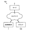
- FIG. 1 is a diagram illustrating an example of a self-position estimation system according to an embodiment of the present disclosure.
- 1 is a block diagram illustrating a more detailed configuration example of a self-position estimation device (system) according to an embodiment of the present disclosure. It is a figure showing an example of the prior art object information table concerning one embodiment of this indication.
- 5 is a flowchart illustrating a schematic flow of a self-position estimation operation according to an embodiment of the present disclosure.
- FIG. 15 is a block diagram illustrating a detailed configuration example of a self-position estimating device (system) according to a modified example of an embodiment of the present disclosure.
- the self-position estimation is performed by estimating the optimal time or time zone (hereinafter, referred to as an optimal time) for creating a preliminary map, and acquiring information for creating a preliminary map at the estimated optimal time. Create a pre-map to improve the accuracy of the map.
- FIG. 1 is a block diagram showing a schematic configuration example of the autonomous mobile according to the present embodiment.
- the autonomous mobile body 1 includes, for example, a CPU (Central Processing Unit) 12, a DRAM (Dynamic Random Access Memory) 13, a flash ROM (Read Only Memory) 14, and a PC (Personal Computer) card interface (I).
- / F) 15, a control unit 10 formed by connecting the wireless communication unit 16 and the signal processing circuit 11 to each other via an internal bus 17, and a battery 18 as a power source of the autonomous mobile unit 1.
- the autonomous mobile body 1 has a movable part 26 such as a joint part of an arm and a leg, a wheel or a caterpillar, and an operating mechanism for realizing an operation such as movement and gesture, and a drive part for driving the movable part. And an actuator 27.
- the autonomous mobile body 1 serves as a sensor for acquiring information such as a moving distance, a moving speed, a moving direction, and a posture (hereinafter, referred to as an inner field sensor) for detecting the direction and the acceleration of the own machine.
- An inertial measurement device (Inertial Measurement Unit) (IMU) 20 and an encoder (or potentiometer) 28 for detecting a driving amount of an actuator 27 are provided.
- an acceleration sensor, an angular velocity sensor, or the like can be used as the inner field sensor.
- the autonomous mobile body 1 captures an external situation as a sensor (hereinafter, referred to as an external sensor) that acquires information such as the terrain around the own device and the distance and direction to an object existing around the own device.
- an external sensor that acquires information such as the terrain around the own device and the distance and direction to an object existing around the own device.
- ToF Time of Flight
- LIDAR Light Detection and Ranging or Laser Imaging and Detection and Ranging
- GPS Global Positioning System
- magnetic sensor magnetic sensor
- Bluetooth registered trademark
- Wi-Fi Wi-Fi
- a measurement unit hereinafter, referred to as a radio field intensity sensor of the radio field intensity in the wireless communication unit 16 such as a trademark may be used.
- the autonomous mobile body 1 includes a touch sensor 22 for detecting a physical pressure received from the outside, a microphone 23 for collecting external sounds, and a speaker 24 for outputting sounds and the like to the surroundings. Also, a display unit 25 for displaying various information to a user or the like may be provided.
- various sensors such as the IMU 20, the touch sensor 22, the ToF sensor 21, the microphone 23, the speaker 24, and the encoder (or potentiometer) 28, the display unit, the actuator 27, the CCD camera (hereinafter simply referred to as a camera) 19, and the battery Reference numerals 18 are connected to the signal processing circuit 11 of the control unit 10, respectively.
- the signal processing circuit 14 sequentially captures sensor data, image data, and audio data supplied from the various sensors described above, and sequentially stores them at predetermined positions in the DRAM 13 via the internal bus 17.
- the signal processing circuit 11 sequentially takes in remaining battery power data indicating the remaining battery power supplied from the battery 18 and stores the data in a predetermined position in the DRAM 13.
- the sensor data, image data, audio data, and battery remaining amount data stored in the DRAM 13 in this manner are used when the CPU 12 controls the operation of the autonomous mobile unit 1 and, if necessary, perform wireless communication.
- the data is transmitted to an external server or the like via the unit 16.
- the wireless communication unit 16 communicates with an external server or the like via a predetermined network such as a wireless LAN (Local Area Network) or a mobile communication network in addition to Bluetooth (registered trademark) and Wi-Fi (registered trademark). It may be a communication unit for performing communication.
- the CPU 12 transmits the control program stored in the memory card 30 or the flash ROM 14 loaded in the PC card slot (not shown) via the PC card interface 15 or directly. Read and store this in the DRAM 13.
- the CPU 12 based on the sensor data, image data, audio data, and remaining battery power data sequentially stored in the DRAM 13 from the signal processing circuit 11 as described above, the status of its own device and the surroundings, and instructions from the user. Judge whether there is any action or not.
- the CPU 12 performs self-position estimation and various operations using map data stored in the DRAM 13 or the like or map data acquired from an external server or the like via the wireless communication unit 16 and various information. .
- the CPU 12 determines the subsequent action based on the above-described determination result, the estimated self-position, the control program stored in the DRAM 13, and drives the necessary actuator 27 based on the determination result.
- various actions such as movement and gesture are executed.
- the CPU 12 generates audio data as necessary, and supplies the generated audio data to the speaker 24 as an audio signal via the signal processing circuit 11 so that the audio based on the audio signal is output to the outside, or the display unit 25 To display various information.
- the autonomous mobile body 1 is configured to be able to act autonomously according to its own device and surrounding conditions, and instructions and actions from the user.
- the configuration of the autonomous mobile 1 described above is merely an example, and various autonomous mobiles can be applied according to purposes and applications. That is, the autonomous mobile object 1 according to the present disclosure is not limited to an autonomous mobile robot such as a domestic pet robot, a robot cleaner, an unmanned aerial vehicle, a following transport robot, and the like, but may include various mobile objects such as a car that estimates its own position. It is possible to apply.
- an autonomous mobile robot such as a domestic pet robot, a robot cleaner, an unmanned aerial vehicle, a following transport robot, and the like
- various mobile objects such as a car that estimates its own position. It is possible to apply.
- SLAM exists as a technique for estimating its own position.
- map matching exists as one of the techniques for realizing SLAM.
- Map matching is, for example, a technique for identifying matching feature points and mismatching feature points between different map data. Moving object detection, map combination, and self-position estimation (also referred to as map search) when performing SLAM are performed. And so on.
- map matching For example, in the moving object detection, two or more map data created using information acquired by the sensor at different times are compared (map matching) to specify a matching feature point and a mismatching feature point.
- a stationary object wall, sign, etc.
- a moving object person, chair, etc.
- map matching is used when a large-scale map data (for example, an advance map) is created by aligning and combining a collection of small-scale map data (for example, an environmental map).
- a large-scale map data for example, an advance map
- small-scale map data for example, an environmental map
- map search a pre-created map is compared with an environment map created in real time (map matching) to identify a location where both match. , Its own position is estimated.
- the high information density means that the number of stationary objects (or the number of feature points) per unit area is large, for example.
- the preliminary map used for the self-position estimation is, for example, an occupied grid map created using information (hereinafter, referred to as outside world information) acquired by an outside world sensor that detects the surrounding environment such as a camera, a ToF sensor, and a LIDAR sensor. And image feature point information. Therefore, if the external information used to create the preliminary map includes moving objects such as people, pets, and chairs, creating a preliminary map using the external information as it is will result in moving objects that have already moved. Since a prior map included as if it were a stationary object is created, the accuracy of self-position estimation by map matching is reduced.
- information on the own device acquired by the inside sensor is referred to as inside information, in contrast to the outside information acquired by the outside sensor.
- a method of removing the moving object information from the external world information acquired for the preparation of the preliminary map can be considered.
- the external information is a still image acquired by a camera
- a region occupied by the moving object in the still image is removed by a mask process or the like.
- the information density of the pre-map is reduced, which may make it difficult to perform highly accurate self-position estimation.
- an information processing apparatus an information processing system, an optimal time estimation method, a self-position estimation method, and a program that enable a highly accurate self-position estimation while suppressing a decrease in the information density of the preliminary map are described. A description will be given.
- FIG. 2 is a block diagram illustrating a schematic configuration example of a self-location estimation device (system) according to the present embodiment.
- the self-position estimating apparatus (system) 100 includes a pre-mapping optimum time estimating unit 101, a self-position estimating pre-map creating unit 102, a pre-map database (map storage unit) 103, A position estimating unit (determining unit) 104.
- Advance map creation optimal time estimating section 101 estimates and determines an optimal time to acquire information used in creating an advance map for a specific area in which autonomous mobile body 1 operates. Specifically, the pre-mapping optimal time estimating unit 101 determines a time zone in which the ratio of the information of the moving object in the external world information acquired by using the external sensor mounted on the autonomous mobile body 1 will be the smallest. It is estimated as an optimal time for acquiring information used in creating a preliminary map, and this time is determined as a time for acquiring information used in creating a preliminary map. For example, the advance map creation optimum time estimation unit 101 determines a time zone in which the proportion of the region occupied by the moving object in the image acquired by the camera (for example, the camera 19 in FIG.
- the advance map creation optimal time estimation unit 101 uses a time zone in which the number of moving objects included in the image acquired by the camera (for example, the camera 19 in FIG. 1) will be the smallest in the creation of the advance map. It is estimated and determined as the optimal time for acquiring the information to be performed.
- the self-position estimating prior map creation unit 102 acquires information on the region where the autonomous mobile 1 operates at the optimal time estimated by the advance map creation optimal time estimating unit 101, and uses the acquired information to advance Create a map.
- the self-position estimation pre-map creation unit 102 stores the data of the prepared pre-map in the pre-map database 103.
- the self-position estimating unit 104 performs the self-position estimation of the autonomous mobile 1 using the pre-map obtained from the pre-map database 103. For example, the self-position estimating unit 104 obtains a pre-map of the area to which the autonomous mobile 1 currently belongs and the surrounding map of the autonomous mobile 1 from the pre-map database 103, and obtains the obtained pre-map and information obtained in real time by the sensor. Is used to estimate the self-position of the autonomous mobile 1. For example, the self-position estimating unit 104 compares the acquired prior map with a local environmental map created from information acquired in real time from the sensor, and identifies a location where both match (map matching). The self-position of the autonomous mobile body 1 is estimated.
- the self-position estimation device (system) 100 shown in FIG. 2 may be realized by the autonomous mobile 1 alone, or the autonomous mobile 1 and the server 2 may be connected to the Internet, a LAN, or the like as shown in FIG. It may be realized by a system (including the case of cloud computing) connected via a predetermined network 3 such as a mobile communication network.
- FIG. 4 is a block diagram showing a more detailed configuration example of the self-position estimating apparatus (system) according to the present embodiment.
- FIG. 2 is a block diagram focusing on the configuration of FIG.
- the pre-map creation optimal time estimating unit 101 and the pre-map self-position estimating unit 102 in the self-position estimating apparatus (system) 100 include a sensor group 111 including an external sensor 112 and an internal sensor 113.
- the sensor group 111, the moving object detecting unit 114, the self-position estimating unit 115, and the pre-map creating unit 118 constitute the pre-map creating unit 102 for self-position estimating.
- the external sensor 112 in the sensor group 111 is a sensor for acquiring information on the environment around the autonomous mobile 1.
- a LIDAR sensor in addition to the camera 19 and the ToF sensor 21, a LIDAR sensor, a GPS sensor, a magnetic sensor, a radio wave intensity sensor, or the like can be used.
- image data which may be a still image or a moving image.
- ToF sensor 21 information on the distance to an object existing around the autonomous mobile 1 and its direction are acquired.
- the inner field sensor 113 is a sensor for acquiring information on the direction, movement, posture, and the like of the autonomous mobile body 1.
- an acceleration sensor, a gyro sensor, or the like can be used in addition to the encoder (or a potentiometer) 28 of each wheel and each joint, the IMU 20, and the like.
- the self-position estimating unit 115 estimates the current position and the posture (self-position) of the autonomous mobile 1 using the external information input from the external sensor 112 and / or the internal information input from the internal sensor 113. .
- a dead reckoning method and a star reckoning method are exemplified as a method of estimating the self-position of the autonomous mobile body 1 (hereinafter, simply referred to as a self-position estimating method).
- self-position estimating section 115 may have the same configuration as self-position estimating section 104, or may have a separate and independent configuration.
- the self-position estimation method of the dead reckoning method refers to a self-position estimation method of the autonomous mobile body 1 using inner field information input from an inner field sensor 113 such as an encoder 28, an IMU 20, an acceleration sensor, a gyro sensor, and a kinematic calculation. This is a method of estimating.
- the dead reckoning self-position estimation method also includes an odometry calculation method based on forward dynamics calculation based on the value of the encoder 28 attached to each joint of the autonomous mobile 1 and information on the geometric shape of the autonomous mobile 1. Have been. Physical quantities that can be acquired as inner world information include speed, acceleration, relative position, angular velocity, and the like.
- the absolute position and orientation required for the self-position estimation are calculated by integrating these physical quantities.
- the self-position estimation by the dead reckoning method has an advantage in that information on the self-position can be continuously calculated without interruption at a constant rate of a higher rate than the external sensor 112.
- since integration processing is performed to estimate an absolute position or posture there is a demerit that a cumulative error occurs in a long-time measurement.
- the self-position estimation method of the star reckoning method refers to autonomous movement by map matching or geometric shape matching using external information input from an external sensor 112 such as a camera 19, a ToF sensor 21, a GPS sensor, a magnetic sensor, and a radio wave intensity sensor. This is a method for estimating the self-position of the body 1.
- the physical quantities that can be acquired as external information include a position, a posture, and the like.
- the self-position estimation based on the star reckoning method has a merit that an absolute position or orientation can be directly calculated from a physical quantity acquired each time. Therefore, for example, it is possible to correct the accumulated error of the position and orientation accumulated by the self-position estimation of the dead reckoning method by the self-position estimation of the star reckoning method.
- it cannot be used in places or situations where it is not possible to obtain information such as pre-maps or radio wave intensity and it has the disadvantage of high computational costs due to the need to process large volumes of data such as images and point cloud data. Also exists.
- more accurate self-position estimation can be performed by combining the self-position estimation by the dead reckoning method and the self-position estimation by the star reckoning method.
- the self-position estimating unit 104 corrects the self-position estimated by the self-position estimation by the dead reckoning method with the self-position estimated by the self-position estimation by the star reckoning method.
- the self-position estimating unit 115 cannot perform self-position estimation by the star recording method if a preliminary map has not been created. Position estimation may be combined.
- the moving object detection unit 114 detects a moving object existing around the autonomous moving object 1 from information acquired by the external sensor 112 such as the camera 19 and the ToF sensor 21.
- a moving object detection method by the moving object detection unit 114 for example, in addition to the above-described moving object detection by map matching, moving object detection using an optical flow, a grid map, or the like can be applied.
- the moving object detection unit 114 specifies the time at which the moving object was detected by referring to, for example, an internal clock mounted in the autonomous moving object 1. Further, the moving object detection unit 114 inputs information on the position or area where the autonomous mobile object 1 was present when the moving object was detected, from the self-position estimation unit 115.
- the moving object detection unit 114 stores the information on the moving object obtained as described above (hereinafter, referred to as prior moving object information) in the prior moving object information database 116.
- prior moving object information the information on the moving object obtained as described above
- the moving object detection unit 114 stores the information on the moving object obtained as described above (hereinafter, referred to as prior moving object information) in the prior moving object information database 116.
- the moving object to be detected includes, for example, humans, animals such as pets, movable furniture such as chairs and potted plants, office equipment, and running objects such as cars and bicycles. There are various moving objects that are assumed to move in.
- the pre-moving object information database 116 receives and stores pre-moving object information from the moving object detecting unit 114.
- the advance moving object information is stored in the advance moving object information database 116 as, for example, data in a table format.
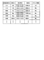
- FIG. 5 shows an example of the advance moving object information table.
- the items of the prior moving object information registered in the prior moving object information table include a moving object type ID, an individual ID, a detection time, an area ID, and gadget information. I have.
- the body type ID is information for identifying the type of a body such as a person, an animal (a cat or a dog), a movable furniture (a chair or a potted plant, etc.).
- the moving object type ID can be generated, for example, by the moving object detecting unit 114 executing a recognition process such as feature point extraction or pattern matching on the external world information.
- Individual ID is information for identifying an individual of a moving object.
- the individual ID is information for identifying an individual.
- This moving object type ID is, for example, a feature point extraction process or a pattern matching process for external world information based on information learned in the past by the moving object detection unit 114 or information registered in advance in a moving object information table by a user. And the like can be generated by executing a recognition process such as.
- the detection time is time information on the time (may be a time or a time zone) when the moving object exists in the target area, and is information on the time or the time zone when the moving object is detected.
- the detection time can be generated, for example, by the time when the moving object detection unit 114 specifies the time at which the external environment sensor 112 has acquired the external world information, or the time at which the external world information has been input from the external world sensor 112.
- Area ID is information for identifying the position or area where the moving object was detected, or the position or area where the autonomous mobile body 1 was present when the moving object was detected.
- region ID for example, information for specifying the position or region input from the self-position estimating unit 115 when the moving object detecting unit 114 detects the moving object can be used.
- the gadget information is information on whether or not a gadget is registered for the moving object when the individual identification (identification of the individual ID) of the moving object is successful, and when the gadget is registered for the moving object. Is the identification information.
- the gadget information may be, for example, information registered directly or indirectly in the advance moving object information table by the administrator of the autonomous mobile object 1 or the owner or administrator of the gadget.
- the gadget 105 in the present embodiment is a wearable terminal such as a mobile phone (including a smartphone), a smart watch, a portable game machine, a portable music player, a digital camera, a notebook personal computer (PC), and the like.
- the communication terminal may be a communication terminal equipped with an external sensor such as the sensor 105a, the IMU 105b, and the radio wave intensity sensor 105c that can specify the current position. Further, information registered in the advance moving object information table may be manually added / changed / deleted via a predetermined communication terminal such as the gadget 105.
- the optimum time estimating unit 117 determines that the ratio of the moving object information to the external world information acquired by using the external environment sensor 112 is the smallest based on the preliminary moving object information registered in the preliminary moving object information database 116. Estimate the deaf time zone. For example, the optimal time estimating unit 117 specifies the number of moving objects existing in the target area for each time zone, and determines the time zone in which the number of moving objects is the smallest based on the number to determine the optimal time for the target area. It is estimated. At this time, the optimal time may be estimated while weighting is performed according to the size of the moving object that can be specified from the moving object type ID or the individual ID.
- a value obtained by multiplying the number of detected persons by 10 is the same as a value obtained by multiplying the number of detected pets by 3. May be summed for each time zone, and the time zone with the smallest score may be estimated as the optimal time. Thereby, it is possible to estimate the time zone in which the proportion of the area occupied by the moving object in the image acquired by the camera 19 will be the smallest as the optimal time for acquiring the information used in creating the pre-map. It becomes.
- the optimal time estimating unit 117 In the estimation of the optimal time by the optimal time estimating unit 117, information acquired by an external sensor (GPS sensor 105a, IMU 105b, radio wave intensity sensor 105c, etc.) mounted on the gadget 105 owned by a person is utilized. Is also good. For example, if a gadget is registered for a moving object (mainly a person) identified by the individual ID in the prior moving object information table, the detection time and the area ID associated with the moving object are registered.
- the information specified by the external sensor of the gadget 105 may be preferentially used to estimate the optimal time.
- a preliminary map is created at an optimum time estimated using the information registered in the preliminary moving object information table
- information for example, presence / absence information
- information obtained in real time by an external sensor of the gadget 105. May be used to determine whether the process can be executed. In this case, for example, when there is a person who should normally go out, it is possible to determine that the preparation of the preliminary map is not executed.
- the optimum time estimated by the optimum time estimating unit 117 may vary depending on the type of the external sensor used, the target area, the weather condition (may be a forecast), the day of the week, and the like. For example, when an external sensor such as the camera 19 that is easily affected by the illuminance is used as the external sensor 112, the optimal time estimating unit 117 determines a high illuminance such as a bright time zone when the sun is coming out or a sunny day. A date and time that are easy to secure may be preferentially estimated as the optimal time.
- the optimal time estimating unit 117 preferentially prefers nighttime when it is estimated that there are relatively few moving objects.
- the optimal time may be estimated.
- an illuminance sensor is separately provided as the external sensor 112, and based on the value obtained by the illuminance sensor, an optimal time is estimated and a determination is made as to whether or not to execute the preliminary map creation process immediately before. May be.
- the illuminance may be detected using the camera 19 instead of the illuminance sensor.
- the optimal time estimating unit 117 instructs the preliminary map creating unit 118 (and, if necessary, the self-position estimating unit 115) to create a preliminary map at the optimal time estimated as described above.
- the preliminary map creator 118 moves the autonomous mobile 1 at the optimal time estimated by the optimal time estimator 117 to obtain external world information on the area for which the preliminary map is to be generated, and obtains the external world information thus obtained. Create a preliminary map using Then, the preliminary map creating unit 118 stores the created preliminary map in the preliminary map database 103.
- the self-position estimating unit 104 obtains, for example, a pre-map around the autonomous mobile 1 or an area to which the autonomous mobile 1 belongs from the pre-map database 103, and obtains the obtained pre-map and the external information input from the external sensor 112.
- the self-position of the autonomous mobile body 1 is estimated by the self-position estimation by the star reckoning method using.
- the self-position estimating unit 104 estimates the self-position of the autonomous moving body 1 by the self-position estimation of the dead reckoning method using the inner world information input from the inner world sensor 113, and Alternatively, a pre-map of the area to which the autonomous mobile unit 1 belongs is obtained from the pre-map database 103, and the self-position estimation is performed by the star reckoning method using the obtained pre-map and the external information input from the external sensor 112. The self-position estimated by the self-position estimation based on the dead reckoning method is corrected based on the self-position obtained by the above.
- each unit incorporated in the autonomous mobile unit 1 is realized by, for example, the CPU 12 (see FIG. 1) reading and executing a control program stored in the memory card 30 or the flash ROM 14.
- the CPU 12 see FIG. 1
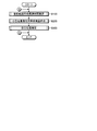
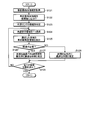
- FIG. 6 is a flowchart illustrating a schematic flow of the self-position estimation operation according to the present embodiment.
- the self-position estimating operation according to the present embodiment mainly includes a pre-mapping optimum time estimating step (step S100) for estimating an optimum time for pre-mapping, and an estimating optimum time.
- a self-position estimating prior map creating step (step S200) for creating a prior map and a self-position estimating step (step S300) for estimating a self-position using the created prior map are included.
- Step S100 in FIG. 6 is started.
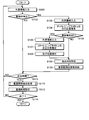
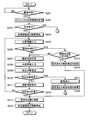
- FIG. 7 is a flowchart illustrating an operation example of the preliminary map creation optimum time estimation step according to the present embodiment.
- the outside world information acquired by the outside world sensor 112 of the autonomous moving object 1 is input to the moving object detection unit 114 (step S101), and the moving object detection is performed.
- the moving object detection is performed in the unit 114 (step S102).
- map matching and optical flow can be used for this moving object detection.
- the information specified by the moving object detection includes, for example, at least one of the moving object type ID and the individual ID.
- step S102 If the moving object is not detected as a result of the moving object detection in step S102 (NO in step S102), the operation proceeds to step S111.
- step S103 the inner-field information acquired by the inner-field sensor 113 is input to the self-position estimating unit 115 (step S103).
- Self-position estimation by the method is executed (step S104). Thereby, the self-position of the autonomous mobile body 1 is estimated.
- step S105 it is determined whether or not a pre-map for the area to which the autonomous mobile object 1 currently belongs has been created and downloaded from the pre-map database 103 (step S105). NO), the operation proceeds to step S109. On the other hand, if the prior map of the corresponding area has been downloaded (YES in step S105), the external information acquired by the external sensor 112 is input to the self-position estimating unit 115 (step S106). Self-position estimation by the star reckoning method is executed (step S107).
- step S104 the self-position estimated by the self-position estimation by the dead reckoning method in step S104 is corrected based on the self-position estimated by the self-position estimation by the star reckoning method in step S107 (step S108), and the process proceeds to step S109.
- the self-position obtained in step S104 or step S108 is information for specifying an area (area ID) in which the moving object has been detected in step S102, and is acquired as one of prior moving object information relating to this moving object. Is done.
- step S109 for example, the current time is specified as the time at which the moving object was detected in step S102 (step S109).
- This time is information for specifying the time (or time zone) at which the moving object was detected in step S102, and is acquired as one of the prior moving object information relating to this moving object.
- the advance moving object information database 116 may be arranged in the autonomous moving object 1 or may be arranged on the server 2 (see FIG. 3) connected to the autonomous moving object 1 via a predetermined network.
- step S111 it is determined whether a predetermined time has been reached.
- the predetermined time is a time at which a process of estimating an optimal time for acquiring information used in creating a pre-map is performed, for example, a predetermined time after the activation of the autonomous mobile body 1. It may be a time. If the predetermined time has not been reached (NO in step S111), the operation returns to step S101. On the other hand, when the predetermined time has been reached (YES in step S111), the optimal time estimating unit 117 executes an optimal time estimating process for estimating an optimal time for acquiring information used in creating a pre-map ( Step S112). A detailed example of the optimal time estimation process will be described later with reference to FIG.
- step S114 After setting the optimal time estimated in step S112 (step S113), it is determined whether or not the operation is to be ended (step S114). If not (NO in step S114), the process returns to step S101. . On the other hand, when the operation is to be ended (YES in step S114), the present operation is ended, and the process returns to the operation illustrated in FIG.
- the optimal time estimation unit 117 acquires a preliminary moving object information table (see FIG. 5) from the preliminary moving object information database 116 (Step S121). Subsequently, the optimal time estimating unit 117 sorts the advance moving object information for each moving object registered in the acquired optimal time information table for each area according to the area ID (step S122).
- the optimal time estimating unit 117 specifies the type of the external sensor 112 used when the autonomous mobile unit 1 acquires the external information for creating a preliminary map (step S123). For example, the optimal time estimating unit 117 determines whether the external sensor 112 used when acquiring external information for creating a pre-map from the pre-registered model or the like of the autonomous mobile body 1 is used when the information such as the camera 19 is acquired. It specifies whether the sensor requires illuminance or a sensor that does not require illuminance, such as the ToF sensor 21 or the LIDAR sensor.
- the optimal time estimating unit 117 selects one unselected region from among the region IDs whose information is registered in the advance moving object information table (step S124), and the moving object detected in the selected region.
- the prior moving object information relating to the moving object information is extracted from the prior moving object information table (step S125).
- the optimal time estimating unit 117 determines whether or not illuminance is required when obtaining external information for creating a preliminary map (step S126). If the illuminance is necessary (YES in step S126), the optimal time estimation unit 117 gives priority to the date and time at which a high illuminance can be easily secured, such as a bright time zone when the sun is coming, and the advance moving object for the selected area. An optimal time is estimated based on the information (step S127).
- the optimum time estimating unit 117 gives priority to nighttime in which the number of moving objects is estimated to be relatively small, based on the prior moving object information on the selected area. An optimal time is estimated (step S128).
- the number of moving objects existing in the target area is specified for each time zone, and the number of moving objects is determined based on the number.
- the time zone in which the number decreases is estimated as the optimal time for the target area.
- the optimal time may be estimated while weighting is performed according to the size of the moving object that can be specified from the moving object type ID or the individual ID.
- the optimal time estimating unit 117 determines whether or not all of the area IDs whose information is registered in the advance moving object information table have been selected (step S129), and if they have been selected (step S129). YES), this operation ends. On the other hand, when there is an unselected area (NO in step S129), the optimal time estimation unit 117 returns to step S124, selects one unselected area, and thereafter performs the same operation. As a result, for each of the area IDs whose information is registered in the advance moving object information table, the optimal time for acquiring the information used in creating the advance map is estimated.
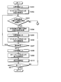
- FIG. 9 is a flowchart illustrating an operation example of the self-position estimation prior map creation step according to the present embodiment. Although the regions are not distinguished in FIG. 9, the self-position estimation preliminary map creation step shown in FIG. 9 may be executed for each region.
- the optimal time estimation unit 117 determines whether or not the optimal time set in the preliminary map creation optimal time estimation step has been reached (Ste S201).
- the optimal time estimating unit 117 acquires external world information from external sensors such as the GPS sensor 105a, the IMU 105b, and the radio wave intensity sensor 105c mounted on the gadget 105 (step S202). Then, it is determined whether or not a preliminary map can be created based on the outside world information (step S203).
- the optimum time estimating unit 117 determines that the creation of the advance map is not permitted when it is specified that the owner is present in the target area based on the outside world information acquired from the outside world sensor of the gadget 105. (NO in step S203). On the other hand, when it is determined that the owner does not exist in the target area, the optimal time estimating unit 117 determines that the creation of the advance map is permitted (YES in step S203).
- Step S203 is not limited to the external information acquired from the external sensor of the gadget 105, and it may be determined whether or not to create a preliminary map based on the illuminance information acquired by the illuminance sensor or the camera 19.
- step S203 If it is determined that the creation of the advance map is not permitted (NO in step S203), the operation returns to, for example, step S100 in FIG. 6, and executes the advance map creation optimal time estimation step again.
- the autonomous mobile body 1 is requested to reach the destination set in advance based on the advance terrain information or the information input by the user. The movement is started (step S204). Alternatively, the autonomous mobile unit 1 starts at random movement. Then, while the autonomous mobile object 1 is moving, the external world information acquired by the external sensor 112 of the autonomous mobile object 1 is sequentially input to the moving object detection unit 114 (step S205). Moving object detection is performed (step S206).
- step S206 for example, the number of moving objects included in the acquired external world information, the ratio of the moving object information in the external world information, and the like are specified.
- step S206 If no moving object is detected in step S206 (NO in step S206), the operation proceeds to step S207. On the other hand, if a moving object is detected (YES in step S206), it is determined whether the number of detected moving objects is larger than a predetermined number set in advance (step S215). If the number of detected moving objects is larger than the predetermined number (YES in step S215), the pre-map created for the area and stored in the pre-map database 103 is discarded (step S216), and this operation is performed. Proceed to step S213. On the other hand, when the number of detected moving objects is equal to or smaller than the predetermined number (NO in step S215), the operation proceeds to step S207.
- step S207 a local environment map around the autonomous mobile 1 is created as a part of the pre-map for the target area by using the external world information input in step S205.
- the inner field information acquired by the inner field sensor 113 of the autonomous moving body 1 is input to the self-position estimating unit 115 (step S208), and the self-position estimating unit 115 performs the self-position estimating by the dead reckoning method. (Step S209).
- it is determined whether the autonomous mobile body 1 has lost its own position step S210.
- the autonomous mobile body 1 is urgently stopped (step S217), and the area has been created and stored in the preliminary map database 103.
- the prior map is discarded (step S218), and then the operation is terminated (see FIG. 6).
- step S210 if the autonomous mobile body 1 has not lost its own position (NO in step S210), the local environment map created in step S207 is subjected to map matching with the pre-map stored in the pre-map database 103.
- the map is stored in the pre-map database 103 while being combined (step S211).
- step S212 it is determined whether or not the autonomous mobile body 1 has reached the destination (step S212). If the autonomous mobile body 1 has not reached the destination (NO in step S212), the process returns to step S205 to create a preliminary map. continue. On the other hand, when the autonomous mobile body 1 has reached the destination (YES in step S212), the autonomous mobile body 1 is moved to a predetermined position, for example, the position at the start of the movement in step S204 (for example, when the charger of the autonomous mobile body 1 is charged). Position) (step S213), and then stop the movement of the autonomous mobile body 1 (step S214), and then return to the operation shown in FIG.
- a predetermined position for example, the position at the start of the movement in step S204 (for example, when the charger of the autonomous mobile body 1 is charged). Position
- FIG. 10 is a flowchart illustrating an operation example of the self-position estimation step according to the present embodiment.
- the inner-field information acquired by the inner-field sensor 113 of the autonomous mobile 1 is input to the self-position estimator 104 (step S301).
- self-position estimating section 104 may have the same configuration as self-position estimating section 115, or may have a separate and independent configuration.
- the self-position estimating unit 104 performs self-position estimation by the dead reckoning method using the input inner world information (step S302). Thereby, the self-position of the autonomous mobile body 1 is estimated.
- the self-position estimating unit 104 determines whether or not a pre-map for the area to which the autonomous mobile 1 currently belongs is stored in the pre-map database 103. It is determined (step S303), and if it is not stored (NO in step S303), the process returns to step S100 in FIG. 6, and the execution from the preliminary map creation optimum time estimation step is repeated. On the other hand, when the pre-map of the area is stored in the pre-map database 103 (YES in step S303), the self-position estimating unit 104 acquires the pre-map of the area from the pre-map database 103 (step S304).
- the self-position estimating unit 104 inputs the inner-field information acquired by the inner-field sensor 113 of the autonomous mobile 1 (step S305), and performs self-position estimation by the dead reckoning method using the input inner-field information. Execute (step S306). Thereby, the self-position of the autonomous mobile body 1 is estimated again.
- the self-position estimating unit 104 determines whether or not the area to which the autonomous moving body 1 belongs has been changed based on the self-position of the autonomous moving body 1 estimated in step S306 (step S307). If YES (YES in step S307), the process returns to step S303 to execute the subsequent operations. On the other hand, when the area to which the autonomous mobile body 1 belongs has not been changed (NO in step S307), the self-position estimating unit 104 inputs the external world information acquired by the external sensor 112 of the autonomous mobile body 1 (step S308). Then, self-position estimation is performed by the star reckoning method using the input external world information and the pre-map obtained in step S304 (step S309).
- the self-position estimating unit 104 corrects the self-position estimated by the self-position estimation by the dead reckoning method in step S306 based on the self-position estimated by the self-position estimation by the star reckoning method in step S309 (step S309). S310).
- step S311 determines whether or not to end the operation (step S311), and if not (NO in step S311), returns to step S305 to execute the subsequent operations. On the other hand, when ending this operation (YES in step S311), self-position estimating section 104 ends this operation.
- the optimal time for acquiring the information used in creating the preliminary map is estimated, and the information for creating the preliminary map is estimated at the estimated optimal time.
- a time zone where the number of moving objects is small is estimated and a preliminary map is created in the time zone.
- the moving object is actually detected. For example, a case where the owner of the autonomous mobile body 1 returns home at a time different from the usual time, a case where a pet or the like starts moving at a time at which the autonomous mobile body 1 does not usually move, and the like can be considered. Therefore, in this embodiment, in order to cope with such a case, the moving object detection (step S206 in FIG. 9) is executed during the self-position estimation prior map creation step, and the detection result satisfies a predetermined condition. In this case (YES in step S215 in FIG. 9), the prior map created and stored in the prior map database 103 is discarded (step S216 in FIG. 9). As a result, it is possible to avoid storing a pre-map having a low information density in the pre-map database 103.
- the self-position estimation pre-map creation step it is necessary to estimate the self-position of the autonomous mobile 1 also during the self-position estimation pre-map creation step (step S209 in FIG. 9), but at this stage, the pre-map is still created. Not even if there is.
- the self-position estimation by the star reckoning method cannot be performed, and the self-position of the autonomous moving body 1 is estimated only by the self-position estimation by the dead reckoning method.
- the occurrence of the accumulated error may cause the autonomous mobile body 1 to lose its own position.
- the prior map created in a state where the autonomous moving body 1 has lost its own position may be an incorrect map. Therefore, in the present embodiment, the autonomous moving body 1 has lost its own position (FIG. 9).
- step S210 (YES in step S210), the autonomous mobile unit 1 is urgently stopped (step S217 in FIG. 9), and the preliminary map created and stored in the preliminary map database 103 is discarded (step S218 in FIG. 9). ). As a result, it is possible to prevent an inaccurate advance map from being stored in the advance map database 103.
- the self-position estimation prior map creation step (step S200 in FIG. 6) is not limited to one time for the activation of the autonomous mobile body 1, but is periodically (for example, every day) repeatedly executed. You may.
- the pre-map creation optimal time estimation step (step S100 in FIG. 6) is also periodically (for example, every day) repeatedly executed to accumulate pre-moving object information on many moving objects in the pre-moving object information database 116. It is possible to estimate the optimal time to obtain the information used in the preparation of the pre-map, and to prepare the pre-map at the optimum time, the information density of the pre-map The decrease is further suppressed, and more accurate self-position estimation becomes possible.
- the external sensor 112 obtains the external information used in the preparation of the pre-map at the optimum time estimated by the optimum time estimating unit 117, and the external sensor 112 obtains the information at the optimum time.
- the present invention is not limited to such a configuration and operation.
- an external world information database (external world information storage unit) 218 that stores the external world information acquired by the external world sensor 112 at the optimal time estimated by the optimal time estimation unit 117 is provided, and a preliminary map creation is performed.
- the unit 118 it is also possible to configure the unit 118 to create a preliminary map using the outside world information stored in the outside world information database 218 at an arbitrary or predetermined time.
- Other configurations and operations of the self-position estimating device (system) 200 shown in FIG. 11 may be the same as those of the self-position estimating device (system) 100 shown in FIG. .
- the present technology may also have the following configurations.
- (1) Based on time information on the time when the moving object has been present in the predetermined area based on the external world information of the predetermined area detected by the external world sensor, to create a preliminary map used when the mobile body estimates its own position based on the time information
- a determination unit that determines an acquisition time for acquiring the information of An information processing device comprising: (2) The information processing apparatus according to (1), wherein the determination unit determines the acquisition time based on a ratio of information of a moving object in external world information obtained using the external world sensor. (3) The information processing device according to (1), wherein the determination unit determines the acquisition time based on the number of moving objects existing in the predetermined area.
- a moving object information storage unit that stores the time information; The information processing apparatus according to (1), wherein the determination unit determines the acquisition time based on the time information stored in the moving object information storage unit.
- a detection unit that detects a moving object present around the external sensor using the external information acquired by the external sensor, The information processing device according to (1), wherein the determination unit determines the acquisition time based on time information specified when the detection unit detects the moving object.
- the apparatus further includes a generation unit that generates a type ID for specifying the type of the moving object based on the external information acquired by the external sensor.
- the information processing device according to (5), wherein the determination unit determines the acquisition time by weighting each time zone based on the time information and the type ID.
- a moving object information storage unit that stores the time information and the type ID relating to the same moving object in association with each other;
- the information processing device according to (6), wherein the determination unit determines the acquisition time based on the time information and the type ID stored in the moving object information storage unit.
- the method according to (1) further including a creating unit that creates a preliminary map using external world information acquired by the external world sensor as information for creating the preliminary map at the acquisition time determined by the determining unit.
- Information processing device is
- the creating unit in the process of creating a preliminary map using information for creating the preliminary map acquired at the acquisition time determined by the determination unit, the external world information acquired by the external sensor Based on the number of moving objects detected on the basis of the above, it is determined whether or not the prior map created based on the information for creating the advance map acquired at the acquisition time is to be discarded.
- An information processing apparatus according to claim 1.
- the image processing apparatus further includes: a generation unit configured to identify the moving object existing around the external sensor and generate an individual ID for identifying the identified moving object; Based on the time information and the individual ID regarding the same moving object, the determination unit determines whether or not a gadget including an external sensor related to the individual identified by the individual ID is provided and the gadget is registered.
- the acquisition time is determined by associating gadget information for identifying the gadget with the individual ID
- the creating unit determines whether the advance map can be created based on the gadget information.
- An inner field sensor that obtains at least one inner field information of a moving distance, a moving speed, a moving direction, and a posture of the moving body;
- a second estimating unit that estimates a second self-position of the moving body using the inner world information acquired by the inner world sensor;
- a generating unit that generates an area ID for specifying an area including the second self-position estimated by the second estimating unit when the moving object is detected,
- the information processing apparatus 11), wherein the determination unit determines the acquisition time for each area based on the time information and the area ID.
- the information processing apparatus in the process of creating a preliminary map using the information for creating the preliminary map acquired at the acquisition time determined by the determination unit, the creating unit, the second estimating unit of the moving body
- the information processing apparatus wherein when the self-position has been lost, the advance map created based on the information for creating the advance map acquired at the acquisition time is discarded.
- the apparatus further includes an inner field sensor for acquiring at least one piece of inner field information of a moving distance, a moving speed, a moving direction, and a posture of the moving body,
- the first estimating unit estimates a second self-position of the moving body using the inner-field information acquired by the inner-field sensor, and corrects the second self-position with the first self-position.
- An information processing device according to 11).
- the first estimating unit acquires the preliminary map created by the creating unit from the map storage unit, and uses the acquired preliminary map and the information acquired by the outside world sensor to acquire the moving object.
- the information processing apparatus according to (11), wherein the first self-position is estimated.
- the external sensor is at least one of a camera, a ToF (Time of Flight) sensor, a LIDAR (Light Detection and Ranging or Laser Imaging Detection and Ranging) sensor, a GPS (Global Positioning System) sensor, a magnetic sensor, and a radio wave intensity sensor.
- the information processing device including: (17) The information processing device according to (12), wherein the inner field sensor includes at least one of an inertial measurement device, an encoder, a potentiometer, an acceleration sensor, and an angular velocity sensor. (18) Based on time information on the time when the moving object has been present in the predetermined area based on the external world information of the predetermined area detected by the external world sensor, to create a preliminary map used when the mobile body estimates its own position based on the time information Determine the acquisition time to get the information of The optimal time estimation method.
- the inner field sensor includes at least one of an inertial measurement device, an encoder, a potentiometer, an acceleration sensor, and an angular velocity sensor.
- a self-position estimating method comprising estimating a self-position of the moving object using the created prior map and the external information acquired by the external sensor.
- the information processing device according to (4), wherein the determination unit determines, based on the time information, a time at which the number of moving objects existing in the predetermined area is estimated to be the smallest as the acquisition time. (23) The creating unit, when the number of moving objects present in the predetermined area exceeds a predetermined number, the creating unit based on the information for creating the advance map acquired at the acquisition time. The information processing device according to (12), wherein the previous map is discarded. (24) (10) The creating unit according to (10), wherein the creating unit specifies a current position of the gadget based on the gadget information, and disables creation of the advance map when the gadget exists in the predetermined area. Information processing device.
- a determination unit that determines an acquisition time for acquiring the information of An information processing system comprising:
Landscapes
- Engineering & Computer Science (AREA)
- Radar, Positioning & Navigation (AREA)
- Remote Sensing (AREA)
- Physics & Mathematics (AREA)
- General Physics & Mathematics (AREA)
- Automation & Control Theory (AREA)
- Theoretical Computer Science (AREA)
- Aviation & Aerospace Engineering (AREA)
- Computer Vision & Pattern Recognition (AREA)
- Multimedia (AREA)
- Evolutionary Computation (AREA)
- Artificial Intelligence (AREA)
- Data Mining & Analysis (AREA)
- Databases & Information Systems (AREA)
- Medical Informatics (AREA)
- Software Systems (AREA)
- Computing Systems (AREA)
- Health & Medical Sciences (AREA)
- General Health & Medical Sciences (AREA)
- Electromagnetism (AREA)
- Bioinformatics & Computational Biology (AREA)
- Bioinformatics & Cheminformatics (AREA)
- Life Sciences & Earth Sciences (AREA)
- Evolutionary Biology (AREA)
- General Engineering & Computer Science (AREA)
- Control Of Position, Course, Altitude, Or Attitude Of Moving Bodies (AREA)
- Navigation (AREA)
Abstract
自己位置推定の精度を向上する。情報処理装置(システム)(100)は、外界センサ(112)によって検出された所定の領域の外界情報に基づく前記所定の領域に動物体が存在した時間に関する時間情報に基づいて、移動体が自己位置を推定する際に使用する事前地図を作成するための情報を取得する取得時間を決定する決定部(117)を備える。
Description
本開示は、情報処理装置、最適時間推定方法、自己位置推定方法及びプログラムを記録した記録媒体に関する。
近年、家庭におけるロボット掃除機やペットロボット、工場や物流倉庫における運搬ロボットなど、人工知能を備えた自律移動体の開発が盛んに行なわれている。
自律移動体においては、目的地まで確実に到達するためだけでなく、周囲の環境に応じて安全に行動する上でも、自機の現在位置や姿勢(以下、自己位置という)を正確に推定することが重要となる。
自己位置を推定するための技術としては、例えば、SLAM(Simultaneous Localization and Mapping)が存在する。SLAMとは、自己位置の推定と環境地図の作成とを同時に行なう技術であり、各種センサで取得された情報を用いて環境地図を作成するのと同時に、この作成された環境地図を用いて自己位置を推定する。環境地図を用いた自己位置の推定では、例えば、予め作成しておいた広域の地図(以下、事前地図という)と、センサでリアルタイムに取得された情報から作成した局所的な環境地図とを比較(マップマッチング)して両者が一致する箇所を特定することで、自己位置が推定される。なお、事前地図とは、例えば、ある領域内に存在する障害物等の環境の形状を2次元地図又は3次元地図として記録した情報であり、環境地図とは、例えば、自律移動体の周囲に存在する障害物等の環境の形状を2次元地図又は3次元地図として表現した情報である。
環境地図を用いた自己位置推定に用いられる事前地図は、例えば、自律移動体自身が対象の領域を移動した際に必要な情報を取得して作成される。ただし、人物や自動車などの多くの動物体が存在する状況下で事前地図を作成した場合、事前地図の精度が低下し、それにより、自己位置推定の精度が低下してしまう。
そこで本開示では、自己位置推定の精度を向上することが可能な情報処理装置、最適時間推定方法、自己位置推定方法及びプログラムを記録した記録媒体を提案する。
上記の課題を解決するために、本開示に係る一形態の情報処理装置は、外界センサによって検出された所定の領域の外界情報に基づく前記所定の領域に動物体が存在した時間に関する時間情報に基づいて、移動体が自己位置を推定する際に使用する事前地図を作成するための情報を取得する取得時間を決定する決定部を備える。
(作用)本開示に係る一形態の情報処理装置によれば、動物体が存在した時間に関する時間情報に基づいて事前地図の作成において使用する情報を取得するのに最適な時間を推定することが可能となるため、より精度の高い自己位置推定を可能にする事前地図を作成することが可能になる。その結果、自己位置推定の精度を向上することが可能な情報処理装置、最適時間推定方法、自己位置推定方法及びプログラムを記録した記録媒体を実現することが可能となる。
本開示によれば、自己位置推定の精度を向上することが可能となる。なお、ここに記載された効果は必ずしも限定されるものではなく、本開示中に記載された何れかの効果であってもよい。
以下に、本開示の一実施形態について図面に基づいて詳細に説明する。なお、以下の実施形態において、同一の部位には同一の符号を付することにより重複する説明を省略する。
また、以下に示す項目順序に従って本開示を説明する。
1.一実施形態
1.1 自律移動体
1.2 自己位置推定装置(システム)
1.2.1 SLAMとマップマッチングについて
1.2.2 自己位置推定装置(システム)の概略構成例
1.2.3 自己位置推定装置(システム)の詳細な構成例
1.3 自己位置推定動作
1.3.1 自己位置推定動作の概略フロー
1.3.2 事前地図作成最適時間推定ステップ
1.3.2.1 最適時間推定処理
1.3.3 自己位置推定用事前地図作成ステップ
1.3.4 自己位置推定ステップ
1.4 作用・効果
1.5 変形例
1.一実施形態
1.1 自律移動体
1.2 自己位置推定装置(システム)
1.2.1 SLAMとマップマッチングについて
1.2.2 自己位置推定装置(システム)の概略構成例
1.2.3 自己位置推定装置(システム)の詳細な構成例
1.3 自己位置推定動作
1.3.1 自己位置推定動作の概略フロー
1.3.2 事前地図作成最適時間推定ステップ
1.3.2.1 最適時間推定処理
1.3.3 自己位置推定用事前地図作成ステップ
1.3.4 自己位置推定ステップ
1.4 作用・効果
1.5 変形例
1.一実施形態
以下、本開示の一実施形態に係る情報処理装置、最適時間推定方法、自己位置推定方法及びプログラムを記録した記録媒体について、図面を参照して詳細に説明する。本実施形態では、事前地図の作成に最適な時刻又は時間帯(以下、最適な時間と称する)を推定し、推定した最適な時間に事前地図作成用の情報を取得することで、自己位置推定の精度向上を可能にする事前地図を作成する。
以下、本開示の一実施形態に係る情報処理装置、最適時間推定方法、自己位置推定方法及びプログラムを記録した記録媒体について、図面を参照して詳細に説明する。本実施形態では、事前地図の作成に最適な時刻又は時間帯(以下、最適な時間と称する)を推定し、推定した最適な時間に事前地図作成用の情報を取得することで、自己位置推定の精度向上を可能にする事前地図を作成する。
1.1 自律移動体
図1は、本実施形態に係る自律移動体の概略構成例を示すブロック図である。図1に示すように、自律移動体1は、例えば、CPU(Central Processing Unit)12、DRAM(Dynamic Random Access Memory)13、フラッシュROM(Read Only Memory)14、PC(Personal Computer)カードインタフェース(I/F)15、無線通信部16及び信号処理回路11が内部バス17を介して相互に接続されることにより形成されたコントロール部10と、この自律移動体1の動力源としてのバッテリ18とを備える。
図1は、本実施形態に係る自律移動体の概略構成例を示すブロック図である。図1に示すように、自律移動体1は、例えば、CPU(Central Processing Unit)12、DRAM(Dynamic Random Access Memory)13、フラッシュROM(Read Only Memory)14、PC(Personal Computer)カードインタフェース(I/F)15、無線通信部16及び信号処理回路11が内部バス17を介して相互に接続されることにより形成されたコントロール部10と、この自律移動体1の動力源としてのバッテリ18とを備える。
また、自律移動体1は、移動やジェスチャーなどの動作を実現するための稼働機構として、腕部及び脚部の関節部分や車輪やキャタピラ等の可動部26と、この可動部を駆動するためのアクチュエータ27とを備える。
さらに、自律移動体1は、移動距離や移動速度や移動方向や姿勢などの情報を取得するためのセンサ(以下、内界センサという)として、自機の向きや動きの加速度を検出するための慣性計測装置(Inertial Measurement Unit:IMU)20と、アクチュエータ27の駆動量を検出するエンコーダ(又はポテンショメータ)28とを備える。なお、内界センサとしては、これらの他にも、加速度センサや角速度センサ等を用いることができる。
さらにまた、自律移動体1は、自機の周囲の地形や自機の周囲に存在する物体までの距離や方向などの情報を取得するセンサ(以下、外界センサという)として、外部の状況を撮像するCCD(Charge Coupled Device)カメラ19と、自機に対して特定の方向に存在する物体までの距離を測定するToF(Time of Flight)センサ21とを備える。なお、外界センサとしては、これらの他にも、LIDAR(Light Detection and Ranging又はLaser Imaging Detection and Ranging)センサ、GPS(Global Positioning System)センサ、磁気センサ、Bluetooth(登録商標)やWi-Fi(登録商標)などの無線通信部16における電波強度の測定部(以下、電波強度センサという)等を用いることができる。
なお、自律移動体1には、外部から受けた物理的な圧力を検出するためのタッチセンサ22や、外部音を集音するためのマイク23や、周囲へ音声等を出力するためのスピーカ24や、ユーザ等へ各種情報を表示するための表示部25などが設けられてもよい。
以上の構成において、IMU20、タッチセンサ22、ToFセンサ21、マイク23、スピーカ24及びエンコーダ(又はポテンショメータ)28などの各種センサ、表示部、アクチュエータ27、CCDカメラ(以下、単にカメラという)19及びバッテリ18は、それぞれコントロール部10の信号処理回路11と接続されている。
信号処理回路l4は、上述の各種センサから供給されるセンサデータや画像データ及び音声データを順次取り込み、これらをそれぞれ内部バス17を介してDRAM13内の所定位置に順次格納する。また、信号処理回路11は、これと共にバッテリ18から供給されるバッテリ残量を表すバッテリ残量データを順次取り込み、これをDRAM13内の所定位置に格納する。
このようにしてDRAM13に格納された各センサデータ、画像データ、音声データ及びバッテリ残量データは、CPU12が自律移動体1の動作制御を行う際に利用されるとともに、必要に応じて、無線通信部16を介して外部のサーバ等へ送信される。なお、無線通信部16は、Bluetooth(登録商標)やWi-Fi(登録商標)などの他、無線LAN(Local Area Network)や移動体通信網等の所定のネットワークを介して外部のサーバ等と通信を行なうための通信部であってよい。
CPU12は、例えば、自律移動体1の電源が投入された初期時、不図示のPCカードスロットに装填されたメモリカード30又はフラッシュROM14に格納された制御プログラムをPCカードインタフェース15を介して又は直接読み出し、これをDRAM13に格納する。
また、CPU12は、上述のように信号処理回路11よりDRAM13に順次格納される各センサデータ、画像データ、音声データ及びバッテリ残量データに基づいて自機及び周囲の状況や、ユーザからの指示及び働きかけの有無などを判断する。
さらに、CPU12は、DRAM13等に格納されている地図データ又は無線通信部16を介して外部のサーバ等から取得した地図データと各種情報とを利用して、自己位置推定や種々の動作を実行する。
そして、CPU12は、上述の判断結果や推定された自己位置やDRAM13に格納されている制御プログラム等に基づいて、その後の行動を決定すると共に、当該決定結果に基づいて必要なアクチュエータ27を駆動させることにより、移動やジェスチャーなどの各種行動を実行する。
その際、CPU12は、必要に応じて音声データを生成し、これを信号処理回路11を介して音声信号としてスピーカ24に与えることにより当該音声信号に基づく音声を外部に出力させたり、表示部25に各種情報を表示させたりする。
このようにして、自律移動体1は、自機及び周囲の状況や、ユーザからの指示及び働きかけに応じて自律的に行動し得るように構成されている。
なお、以上で説明した自律移動体1の構成は、単なる一例に過ぎず、目的や用途に応じて種々の自律移動体を適用することが可能である。すなわち、本開示における自律移動体1には、家庭内ペットロボットなどの自律移動ロボットやロボット掃除機や無人航空機や追従運搬ロボットなどに限られず、自動車などの自己位置を推定する種々の移動体を適用することが可能である。
1.2 自己位置推定装置(システム)
つづいて、自律移動体1の自己位置を推定する自己位置推定装置(システム)について、図面を用いて詳細に説明する。
つづいて、自律移動体1の自己位置を推定する自己位置推定装置(システム)について、図面を用いて詳細に説明する。
1.2.1 SLAMとマップマッチングについて
上述したように、自己位置を推定するための技術としては、例えば、SLAMが存在する。ここで、SLAMを実現するための技術の一つとして、マップマッチングが存在する。マップマッチングとは、例えば、異なる地図データ間において一致する特徴点と不一致の特徴点とを特定する技術であり、SLAMを行なう際の動物体検出、地図結合、自己位置推定(地図検索ともいう)等において用いられる。
上述したように、自己位置を推定するための技術としては、例えば、SLAMが存在する。ここで、SLAMを実現するための技術の一つとして、マップマッチングが存在する。マップマッチングとは、例えば、異なる地図データ間において一致する特徴点と不一致の特徴点とを特定する技術であり、SLAMを行なう際の動物体検出、地図結合、自己位置推定(地図検索ともいう)等において用いられる。
例えば、動物体検出では、異なる時刻にセンサで取得された情報を用いて作成した2つ以上の地図データを比較(マップマッチング)して一致する特徴点と不一致の特徴点とを特定することで、地図データに含まれる静止物体(壁、標識等)と動物体(人、イス等)とが識別される。
地図結合では、小規模な地図データ(例えば環境地図)の集まりを位置合せ・結合して大規模な地図データ(例えば事前地図)を作成する際にマップマッチングが用いられる。
自己位置推定(地図検索)では、上述したように、予め作成しておいた事前地図と、リアルタイムに作成された環境地図とを比較(マップマッチング)して両者が一致する箇所を特定することで、自己位置が推定される。
このようなマップマッチングを用いたSLAMでは、特に自己位置推定において、情報密度の高い事前地図を用意することが、その精度を向上する上で重要となる。なお、情報密度が高いとは、例えば、単位面積あたりに含まれる静止物体の数(特徴点の数であってもよい)が多いことなどである。
自己位置推定に使用される事前地図は、例えば、カメラ、ToFセンサ、LIDARセンサ等の周囲の環境を検出する外界センサで取得した情報(以下、外界情報という)を用いて作成された占有格子地図や画像特徴点情報などである。そのため、事前地図作成に用いた外界情報に人、ペット、椅子などの動物体が含まれていた場合、そのままの外界情報を用いて事前地図を作成すると、既に移動してしまっている動物体が静止物体であるかのように含まれる事前地図が作成されてしまうため、マップマッチングによる自己位置推定の精度が低下してしまう。なお、以下の説明において、外界センサで取得された外界情報に対し、内界センサで取得された自機に関する情報を内界情報という。
動物体が静止物体として事前地図に含まれることを回避する方法としては、事前地図作成のために取得した外界情報から動物体の情報を除去する方法が考えられる。この方法によれば、例えば、外界情報がカメラで取得した静止画像である場合には、当該静止画像において動物体が占める領域がマスク処理等により除去される。ただし、この方法では、事前地図作成に使用する情報の量が削減されるため、事前地図の情報密度が低下し、それにより、精度の高い自己位置推定が困難になる可能性がある。そこで本実施形態では、事前地図の情報密度の低下を抑制して、精度の高い自己位置推定を可能にする情報処理装置、情報処理システム、最適時間推定方法、自己位置推定方法及びプログラムについて、例を挙げて説明する。
1.2.2 自己位置推定装置(システム)の概略構成例
図2は、本実施形態に係る自己位置推定装置(システム)の概略構成例を示すブロック図である。図2に示すように、自己位置推定装置(システム)100は、事前地図作成最適時間推定部101と、自己位置推定用事前地図作成部102と、事前地図データベース(地図記憶部)103と、自己位置推定部(決定部)104とを備える。
図2は、本実施形態に係る自己位置推定装置(システム)の概略構成例を示すブロック図である。図2に示すように、自己位置推定装置(システム)100は、事前地図作成最適時間推定部101と、自己位置推定用事前地図作成部102と、事前地図データベース(地図記憶部)103と、自己位置推定部(決定部)104とを備える。
事前地図作成最適時間推定部101は、自律移動体1が稼働する特定の領域について、事前地図の作成において使用する情報を取得するのに最適な時間を推定して決定する。具体的には、事前地図作成最適時間推定部101は、自律移動体1が搭載する外界センサを用いて取得した外界情報において動物体の情報が占める割合が最も小さくなるであろう時間帯を、事前地図の作成において使用する情報を取得するのに最適な時間として推定し、この時間を事前地図の作成において使用する情報を取得する時間として決定する。例えば、事前地図作成最適時間推定部101は、外界センサであるカメラ(例えば、図1のカメラ19)で取得した画像における動物体が占める領域の割合が最も小さくなるであろう時間帯を、事前地図の作成において使用する情報を取得するのに最適な時間として推定して決定する。又は、事前地図作成最適時間推定部101は、カメラ(例えば、図1のカメラ19)で取得した画像に含まれる動物体の数が最も小さくなるであろう時間帯を、事前地図の作成において使用する情報を取得するのに最適な時間として推定して決定する。
自己位置推定用事前地図作成部102は、事前地図作成最適時間推定部101で推定された最適な時間に、自律移動体1が稼働する領域に関する情報を取得し、この取得した情報を用いて事前地図を作成する。また、自己位置推定用事前地図作成部102は、作成した事前地図のデータを事前地図データベース103に格納する。
自己位置推定部104は、事前地図データベース103から取得した事前地図を用いて自律移動体1の自己位置推定を実行する。例えば、自己位置推定部104は、自律移動体1が現在属する領域や自律移動体1の周囲の事前地図を事前地図データベース103から取得し、この取得した事前地図と、センサでリアルタイムに取得した情報とを用いて、自律移動体1の自己位置を推定する。例えば、自己位置推定部104は、取得した事前地図と、センサからリアルタイムに取得した情報から作成した局所的な環境地図とを比較して両者が一致する箇所を特定(マップマッチング)することで、自律移動体1の自己位置を推定する。
なお、図2に示す自己位置推定装置(システム)100は、自律移動体1単体で実現されてもよいし、図3に示すような、自律移動体1とサーバ2とが、インターネットやLANや移動体通信網等の所定のネットワーク3を介して接続されたシステム(クラウド・コンピューティングの場合を含む)によって実現されてもよい。
1.2.3 自己位置推定装置(システム)の詳細な構成例
つづいて、本実施形態に係る自己位置推定装置(システム)100のより詳細な構成例を、以下に図面を用いて詳細に説明する。図4は、本実施形態に係る自己位置推定装置(システム)のより詳細な構成例を示すブロック図であって、特に、事前地図作成最適時間推定部101と、自己位置推定用事前地図作成部102との構成に着目したブロック図である。
つづいて、本実施形態に係る自己位置推定装置(システム)100のより詳細な構成例を、以下に図面を用いて詳細に説明する。図4は、本実施形態に係る自己位置推定装置(システム)のより詳細な構成例を示すブロック図であって、特に、事前地図作成最適時間推定部101と、自己位置推定用事前地図作成部102との構成に着目したブロック図である。
図4に示すように、自己位置推定装置(システム)100における事前地図作成最適時間推定部101及び自己位置推定用事前地図作成部102は、外界センサ112と内界センサ113とを含むセンサ群111と、動物体検出部(検出部、生成部)114と、自己位置推定部115と、事前動物体情報データベース(動物体情報記憶部)116と、最適時間推定部117と、事前地図作成部118とから構成されている。これらのうち、例えば、センサ群111と、動物体検出部114と、自己位置推定部115と、事前動物体情報データベース116と、最適時間推定部117とは、事前地図作成最適時間推定部101を構成する。また、例えば、センサ群111と、動物体検出部114と、自己位置推定部115と、事前地図作成部118とは、自己位置推定用事前地図作成部102を構成する。
センサ群111における外界センサ112は、自律移動体1の周囲の環境の情報を取得するためのセンサである。この外界センサ112には、カメラ19やToFセンサ21の他に、LIDARセンサ、GPSセンサ、磁気センサ、電波強度センサ等を用いることができる。例えば、外界センサ112にカメラ19を用いた場合、自律移動体1の周囲の情報が画像データ(静止画、動画のいずれであってもよい)として取得される。また、外界センサ112にToFセンサ21を用いた場合、自律移動体1の周囲に存在する物体までの距離とその方向に関する情報が取得される。
内界センサ113は、自律移動体1の向きや動きや姿勢等に関する情報を取得するためのセンサである。この内界センサ113には、車輪や各関節のエンコーダ(ポテンショメータであってもよい)28、IMU20等の他に、加速度センサやジャイロセンサなどを用いることができる。
自己位置推定部115は、外界センサ112から入力された外界情報及び/又は内界センサ113から入力された内界情報を用いて、自律移動体1の現在位置及び姿勢(自己位置)を推定する。本実施形態では、自律移動体1の自己位置の推定方法(以下、単に自己位置推定方法という)として、デッドレコニング方式と、スターレコニング方式とを例示する。なお、自己位置推定部115は、自己位置推定部104と同一の構成であってもよいし、別途独立した構成であってもよい。
デッドレコニング方式の自己位置推定方法とは、エンコーダ28やIMU20や加速度センサやジャイロセンサや運動力学的な演算などの内界センサ113から入力された内界情報を用いて自律移動体1の自己位置を推定する方法である。このデッドレコニング方式の自己位置推定方法には、自律移動体1の各関節に取り付けられたエンコーダ28の値と自律移動体1の幾何形状の情報とから、順動力学計算によるオドメトリ算出手法も含まれている。内界情報として取得可能な物理量には、速度、加速度、相対位置、角速度などが含まれる。デッドレコニング方式の自己位置推定では、これらの物理量を積算することで、自己位置推定に必要な絶対的な位置や姿勢が算出される。このデッドレコニング方式の自己位置推定は、外界センサ112と比較して高いレートの一定の周期で途切れることなく連続的に自己位置の情報を演算可能である点でメリットを有する。ただし、デッドレコニング方式の自己位置推定では、絶対的な位置や姿勢を推定するために積分処理が行なわれることから、長時間の計測で累積誤差が発生するというデメリットも存在する。
スターレコニング方式の自己位置推定方法とは、カメラ19やToFセンサ21やGPSセンサや磁気センサや電波強度センサなどの外界センサ112から入力された外界情報を用いたマップマッチングや幾何形状マッチングにより自律移動体1の自己位置を推定する方法である。外界情報として取得可能な物理量には、位置、姿勢などが含まれる。スターレコニング方式の自己位置推定では、都度取得された物理量から絶対的な位置や姿勢を直接算出することができるというメリットが存在する。そのため、例えば、デッドレコニング方式の自己位置推定で蓄積した位置や姿勢の累積誤差を、スターレコニング方式の自己位置推定で補正することが可能である。ただし、事前地図や電波強度の情報などを取得できない場所や状況では使用することができないというデメリットや、画像やポイントクラウドデータなどの大容量のデータを処理する必要があるため計算コストが高いというデメリットも存在する。
そこで本実施形態では、デッドレコニング方式による自己位置推定とスターレコニング方式による自己位置推定とを組み合わせることで、より精度の高い自己位置推定を可能にする。具体的には、自己位置推定部104は、デッドレコニング方式による自己位置推定で推定された自己位置を、スターレコニング方式による自己位置推定で推定された自己位置で補正する。なお、自己位置推定部115については、事前地図が未作成である場合にはスターレコニング方式による自己位置推定ができないため、可能な場合に適宜、デッドレコニング方式による自己位置推定とスターレコニング方式による自己位置推定とが組み合わされてよい。
動物体検出部114は、カメラ19やToFセンサ21などの外界センサ112により取得された情報から、自律移動体1の周囲に存在する動物体を検出する。動物体検出部114による動物体の検出手法には、例えば、上述したようなマップマッチングによる動物体検出の他に、オプティカルフローやグリッドマップなどを用いた動物体検出を適用することができる。また、動物体検出部114は、例えば自律移動体1内に搭載された内部時計を参照することで、動物体が検出された時刻を特定する。さらに、動物体検出部114は、上記動物体を検出した際に自律移動体1が存在していた位置又は領域の情報を自己位置推定部115から入力する。そして、動物体検出部114は、以上のようにして取得した動物体に関する情報(以下、事前動物体情報という)を事前動物体情報データベース116に格納する。なお、動物体検出部114が検出する事前動物体情報の項目は、事前動物体情報データベース116の説明の際に触れる。また、本実施形態において、検出対象となる動物体としては、例えば、人、ペットなどの動物、イスや鉢植えの植物などの移動可能な家具や事務機器、自動車や自転車等の走行体等、日常において移動することが想定される種々の動物体を挙げることができる。
事前動物体情報データベース116は、動物体検出部114から事前動物体情報を受信して格納する。事前動物体情報は、例えば、テーブル形式のデータとして事前動物体情報データベース116に格納される。図5に、事前動物体情報テーブルの一例を示す。図5に示すように、事前動物体情報テーブルに登録される事前動物体情報の項目には、動物体種別IDと、個体IDと、検出時刻と、領域IDと、ガジェット情報とが含まれている。
動物体種別IDとは、人、動物(ネコやイヌ等)、移動可能な家具(イスや鉢植えの植物等)等の動物体の種別を識別するための情報である。この動物体種別IDは、例えば、動物体検出部114が外界情報に対して特徴点抽出やパターンマッチング等の認識処理を実行することで生成することが可能である。
個体IDとは、動物体の個体を識別するための情報であり、例えば動物体が人であれば、個人を識別するための情報である。この動物体種別IDは、例えば、動物体検出部114が過去に学習した情報やユーザによって事前に動物体情報テーブルに登録された情報等に基づいて、外界情報に対する特徴点抽出処理やパターンマッチング処理等の認識処理を実行することで生成することができる。
検出時刻とは、対象の領域にその動物体が存在した時間(時刻又は時間帯であってよい)に関する時間情報であって、その動物体を検出した時刻若しくは時間帯に関する情報である。この検出時刻は、例えば、外界センサ112が外界情報を取得した時刻、又は、外界センサ112から外界情報が入力された時刻を動物体検出部114が特定することで生成することができる。
領域IDとは、その動物体を検出した位置又は領域、又は、その動物体を検出した際に自律移動体1が存在していた位置又は領域を特定する情報である。この領域IDには、例えば、動物体検出部114が動物体を検出した際に自己位置推定部115から入力された位置又は領域を特定するための情報を用いることが可能である。
ガジェット情報とは、その動物体の個体識別(個体IDの特定)に成功している場合において、その動物体に対してガジェットが登録されているか否かに関する情報、及び、登録されている場合にはその識別情報である。このガジェット情報は、例えば、自律移動体1の管理者又はガジェットの所有者若しくは管理者等が事前動物体情報テーブルに直接又は間接に登録した情報であってよい。なお、本実施形態におけるガジェット105とは、携帯電話(スマートフォンを含む)やスマートウォッチや携帯ゲーム機や携帯音楽プレーヤやデジタルカメラやノート型パーソナルコンピュータ(PC)などのウエアラブル端末等であって、GPSセンサ105a、IMU105b、電波強度センサ105cなどの現在位置を特定することを可能にする外界センサを搭載した通信端末であってよい。また、事前動物体情報テーブルに登録されている情報は、ガジェット105などの所定の通信端末を介して、手動で追加・変更・削除することが可能であってもよい。
図4に戻り説明する。最適時間推定部117は、事前動物体情報データベース116に登録されている事前動物体情報を元に、外界センサ112を用いて取得した外界情報において動物体の情報が占める割合が最も小さくなるであろう時間帯を推定する。例えば、最適時間推定部117は、時間帯ごとに対象の領域に存在する動物体の数を特定し、その数に基づいて動物体の数が最も少なくなる時間帯を対象の領域に対する最適な時間と推定する。その際、動物体種別IDや個体ID等から特定できる動物体の大きさに応じて重み付けをしつつ、最適な時間を推定してもよい。例えば、人の重みを10とし、人よりもサイズの小さいペットの重みを3とした場合、検出された人の数に10を乗算した値と同じく検出されたペットの数に3を乗算した値とを時間帯ごとに合計するスコアリングを行い、最もスコアの小さい時間帯を最適な時間と推定してもよい。それにより、カメラ19で取得した画像における動物体が占める領域の割合が最も小さくなるであろう時間帯を、事前地図の作成において使用する情報を取得するのに最適な時間として推定することが可能となる。
また、最適時間推定部117による最適な時間の推定では、人が所有するガジェット105に搭載されている外界センサ(GPSセンサ105a、IMU105b、電波強度センサ105c等)で取得された情報が活用されてもよい。例えば、事前動物体情報テーブルにおいて、個体IDにより個体識別がなされた動物体(主に人)に対してガジェットが登録されていた場合には、この動物体に対応付けられた検出時刻及び領域IDの情報よりも、ガジェット105の外界センサにより特定された情報(例えば在/不在の時間帯に関する情報)を優先的に使用して、最適な時間が推定されてもよい。又は、事前動物体情報テーブルに登録された情報を用いて推定された最適な時間に事前地図作成を実行するに際して、ガジェット105の外界センサでリアルタイムに得られた情報(例えば在/不在の情報)から当該処理実行の可否を判断してもよい。その場合、例えば、通常では出かけているはずの人物が居る場合には事前地図の作成を実行しないと判断することが可能となる。
さらに、最適時間推定部117によって推定される最適な時間は、使用する外界センサの種類や対象領域や気象条件(予報でもよい)や曜日等によって変化してもよい。例えば、最適時間推定部117は、外界センサ112としてカメラ19などの照度の影響を受け易い外界センサが使用される場合には、日が出ている明るい時間帯や晴れの日など、高い照度を確保しやすい日時を優先的に最適な時間と推定してもよい。これに対し、ToFセンサ21やLIDARセンサなどの照度の影響を受け難い外界センサが使用される場合には、最適時間推定部117は、比較的動物体が少ないと推測される夜間を優先的に最適な時間と推定してもよい。ただし、照度については、外界センサ112として別途、照度センサを設け、この照度センサで得られた値に基づいて、最適な時間の推定や、直前での事前地図作成処理実行の可否判断が実行されてもよい。なお、照度センサの代わりにカメラ19を用いて照度が検出されてもよい。
最適時間推定部117は、上記のようにして推定した最適な時間に事前地図を作成することを、事前地図作成部118へ(必要であれば自己位置推定部115へも)指示する。
事前地図作成部118は、最適時間推定部117で推定された最適な時間に、自律移動体1を移動させて事前地図作成対象の領域に関する外界情報を取得し、これにより取得された外界情報を用いて事前地図を作成する。そして、事前地図作成部118は、作成した事前地図を事前地図データベース103に格納する。
自己位置推定部104は、例えば、自律移動体1の周囲又は自律移動体1が属する領域の事前地図を事前地図データベース103から取得し、取得した事前地図と外界センサ112から入力された外界情報とを用いたスターレコニング方式による自己位置推定にて、自律移動体1の自己位置を推定する。又は、自己位置推定部104は、内界センサ113から入力された内界情報を用いたデッドレコニング方式の自己位置推定にて自律移動体1の自己位置を推定するとともに、自律移動体1の周囲又は自律移動体1が属する領域の事前地図を事前地図データベース103から取得し、取得した事前地図と外界センサ112から入力された外界情報とを用いたスターレコニング方式による自己位置推定を実行し、これにより得られた自己位置に基づいて、デッドレコニング方式の自己位置推定にて推定された自己位置を補正する。
なお、図4に示すブロック構成を図3に示すシステム構成にて実現する場合には、例えば、センサ群111と動物体検出部114と自己位置推定部115及び104とが自律移動体1に組み込まれ、自己位置推定部115と事前動物体情報データベース116と最適時間推定部117と事前地図作成部118と事前地図データベース103とがサーバ2に組み込まれる。その場合、自律移動体1に組み込まれる各部は、例えばCPU12(図1参照)がメモリカード30又はフラッシュROM14に格納された制御プログラムを読み出して実行することで実現される。ただし、このような配置に限定されず、種々変形することが可能である。
1.3 自己位置推定動作
つぎに、本実施形態に係る自己位置推定動作について、以下に図面を参照して詳細に説明する。
つぎに、本実施形態に係る自己位置推定動作について、以下に図面を参照して詳細に説明する。
1.3.1 自己位置推定動作の概略フロー
図6は、本実施形態に係る自己位置推定動作の概略的な流れを示すフローチャートである。図6に示すように、本実施形態に係る自己位置推定動作は、主として、事前地図作成の最適な時間を推定する事前地図作成最適時間推定ステップ(ステップS100)と、推定された最適な時間に事前地図を作成する自己位置推定用事前地図作成ステップ(ステップS200)と、作成された事前地図を用いて自己位置を推定する自己位置推定ステップ(ステップS300)とからなる。
図6は、本実施形態に係る自己位置推定動作の概略的な流れを示すフローチャートである。図6に示すように、本実施形態に係る自己位置推定動作は、主として、事前地図作成の最適な時間を推定する事前地図作成最適時間推定ステップ(ステップS100)と、推定された最適な時間に事前地図を作成する自己位置推定用事前地図作成ステップ(ステップS200)と、作成された事前地図を用いて自己位置を推定する自己位置推定ステップ(ステップS300)とからなる。
1.3.2 事前地図作成最適時間推定ステップ
自律移動体1が起動して稼働を開始すると、自律移動体1を含む自己位置推定装置(システム)100は、まず、事前地図作成最適時間推定ステップ(図6のステップS100)を開始する。図7は、本実施形態に係る事前地図作成最適時間推定ステップの動作例を示すフローチャートである。
自律移動体1が起動して稼働を開始すると、自律移動体1を含む自己位置推定装置(システム)100は、まず、事前地図作成最適時間推定ステップ(図6のステップS100)を開始する。図7は、本実施形態に係る事前地図作成最適時間推定ステップの動作例を示すフローチャートである。
図7に示すように、事前地図作成最適時間推定ステップでは、まず、自律移動体1の外界センサ112で取得された外界情報が動物体検出部114に入力されて(ステップS101)、動物体検出部114において動物体検出が実行される(ステップS102)。この動物体検出には、上述したように、マップマッチングやオプティカルフローなどを用いることができる。また、この動物体検出により特定される情報には、例えば、動物体種別ID及び個体IDのうちの少なくとも1つが含まれている。
ステップS102の動物体検出の結果、動物体が検出されなかった場合(ステップS102のNO)、本動作は、ステップS111へ進む。一方、動物体が検出された場合(ステップS102のYES)、内界センサ113で取得された内界情報が自己位置推定部115に入力されて(ステップS103)、自己位置推定部115においてデッドレコニング方式による自己位置推定が実行される(ステップS104)。これにより、自律移動体1の自己位置が推定される。
つづいて、例えば自律移動体1が現在属する領域についての事前地図が作成済みであって事前地図データベース103からダウンロード済みであるか否かが判断され(ステップS105)、ダウンロード済みでない場合(ステップS105のNO)、本動作がステップS109へ進む。一方、該当領域の事前地図をダウンロード済みである場合(ステップS105のYES)、外界センサ112で取得された外界情報が自己位置推定部115へ入力されて(ステップS106)、自己位置推定部115においてスターレコニング方式による自己位置推定が実行される(ステップS107)。
そして、ステップS104のデッドレコニング方式による自己位置推定で推定された自己位置を、ステップS107のスターレコニング方式による自己位置推定で推定された自己位置に基づいて補正し(ステップS108)、ステップS109へ進む。なお、ステップS104又はステップS108で得られた自己位置は、ステップS102で動物体を検出した領域(領域ID)を特定するための情報であり、この動物体に関する事前動物体情報の一つとして取得される。
また、ステップS109では、ステップS102で動物体を検出した時刻として、例えば現在の時刻が特定される(ステップS109)。この時刻は、ステップS102で動物体を検出した時刻(又は時間帯)を特定するための情報であり、この動物体に関する事前動物体情報の一つとして取得される。
つぎに、以上のようにして取得された事前動物体情報が、事前動物体情報データベース116に格納される(ステップS110)。事前動物体情報データベース116は、自律移動体1内に配置されてもよいし、自律移動体1と所定のネットワークを介して接続されたサーバ2(図3参照)側に配置されてもよい。
ステップS111では、所定の時刻に達したか否かが判定される。なお、ここでの所定の時刻とは、事前地図の作成において使用する情報を取得するのに最適な時間の推定処理を実行する時刻であり、例えば、自律移動体1の起動から所定時間後の時刻などであってよい。所定の時刻に達していない場合(ステップS111のNO)、本動作は、ステップS101へリターンする。一方、所定の時刻に達している場合(ステップS111のYES)、最適時間推定部117が事前地図の作成において使用する情報を取得するのに最適な時間の推定する最適時間推定処理を実行する(ステップS112)。最適時間推定処理の詳細な例については、後述において図8を用いて説明する。
その後、ステップS112で推定された最適時間を設定(ステップS113)した後、本動作を終了するか否かを判定し(ステップS114)、終了しない場合(ステップS114のNO)、ステップS101へリターンする。一方、終了する場合(ステップS114のYES)、本動作を終了して、図6に示す動作へリターンする。
1.3.2.1 最適時間推定処理
ここで、図7のステップS112における最適時間推定処理の一例について、図8を用いて詳細に説明する。図8に示すように、本実施形態に係る最適時間推定処理では、最適時間推定部117は、事前動物体情報データベース116から事前動物体情報テーブル(図5参照)を取得する(ステップS121)。つづいて、最適時間推定部117は、取得した最適時間情報テーブルに登録されている動物体ごとの事前動物体情報を、領域IDにしたがって、領域ごとに仕分けする(ステップS122)。
ここで、図7のステップS112における最適時間推定処理の一例について、図8を用いて詳細に説明する。図8に示すように、本実施形態に係る最適時間推定処理では、最適時間推定部117は、事前動物体情報データベース116から事前動物体情報テーブル(図5参照)を取得する(ステップS121)。つづいて、最適時間推定部117は、取得した最適時間情報テーブルに登録されている動物体ごとの事前動物体情報を、領域IDにしたがって、領域ごとに仕分けする(ステップS122)。
つぎに、最適時間推定部117は、自律移動体1が事前地図作成用の外界情報を取得する際に使用する外界センサ112の種類を特定する(ステップS123)。例えば、最適時間推定部117は、予め登録されている自律移動体1の型式等から、事前地図作成用の外界情報を取得する際に使用する外界センサ112が、カメラ19などの情報取得時の照度が必要なセンサであるか、ToFセンサ21やLIDARセンサなどの照度を必要としないセンサであるかを特定する。
つぎに、最適時間推定部117は、事前動物体情報テーブルに情報が登録されている領域IDのうち未選択の領域を1つ選択し(ステップS124)、この選択した領域で検出された動物体に関する事前動物体情報を事前動物体情報テーブルから抽出する(ステップS125)。
つぎに、最適時間推定部117は、ステップS123で特定した外界センサ112の種類に基づいて、事前地図作成用の外界情報の取得時に照度が必要であるか否かを判定する(ステップS126)。照度が必要である場合(ステップS126のYES)、最適時間推定部117は、日が出ている明るい時間帯など、高い照度を確保しやすい日時を優先しつつ、選択した領域についての事前動物体情報に基づいて、最適な時間を推定する(ステップS127)。一方、照度が必要でない場合(ステップS126のNO)、最適時間推定部117は、比較的動物体が少ないと推測される夜間を優先しつつ、選択した領域についての事前動物体情報に基づいて、最適な時間を推定する(ステップS128)。
なお、ステップS127又はS128における最適な時間の推定では、上述したように、例えば、時間帯ごとに対象の領域に存在する動物体の数が特定され、その数に基づいて動物体の数が最も少なくなる時間帯が対象の領域に対する最適な時間として推定される。その際、動物体種別IDや個体ID等から特定できる動物体の大きさに応じて重み付けをしつつ、最適な時間が推定されてもよい。
その後、最適時間推定部117は、事前動物体情報テーブルに情報が登録されている領域IDの全てを選択済みであるか否かを判定し(ステップS129)、選択済みである場合(ステップS129のYES)、本動作を終了する。一方、未選択の領域が存在する場合(ステップS129のNO)、最適時間推定部117は、ステップS124へリターンして未選択の領域を1つ選択し、以降、同様の動作を実行する。これにより、事前動物体情報テーブルに情報が登録されている領域IDそれぞれに対して、事前地図の作成において使用する情報を取得するのに最適な時間が推定される。
1.3.3 自己位置推定用事前地図作成ステップ
事前地図作成最適時間推定ステップが完了すると、つづいて自己位置推定用事前地図作成ステップ(図6のステップS200)が実行される。図9は、本実施形態に係る自己位置推定用事前地図作成ステップの動作例を示すフローチャートである。なお、図9では、領域が区別されていないが、領域ごとに図9に示す自己位置推定用事前地図作成ステップが実行されてもよい。
事前地図作成最適時間推定ステップが完了すると、つづいて自己位置推定用事前地図作成ステップ(図6のステップS200)が実行される。図9は、本実施形態に係る自己位置推定用事前地図作成ステップの動作例を示すフローチャートである。なお、図9では、領域が区別されていないが、領域ごとに図9に示す自己位置推定用事前地図作成ステップが実行されてもよい。
図9に示すように、自己位置推定用事前地図作成ステップでは、まず、最適時間推定部117が、事前地図作成最適時間推定ステップにて設定した最適な時間に達したか否かを判断する(ステップS201)。最適な時間に達した場合(ステップS201のYES)、最適時間推定部117は、ガジェット105が搭載するGPSセンサ105aやIMU105bや電波強度センサ105c等の外界センサから外界情報を取得し(ステップS202)、この外界情報に基づいて、事前地図の作成の可否を判断する(ステップS203)。例えば、最適時間推定部117は、ガジェット105の外界センサから取得した外界情報に基づいて、その所有者が対象の領域内に存在することを特定した場合、事前地図の作成を不許可と判断する(ステップS203のNO)。一方、最適時間推定部117は、所有者が対象の領域内に存在しないことを特定した場合、事前地図の作成を許可と判断する(ステップS203のYES)。なお、ステップS203は、ガジェット105の外界センサから取得した外界情報に限られず、照度センサやカメラ19で取得された照度情報に基づいて、事前地図の作成の可否が判断されてもよい。
事前地図の作成を不許可と判断した場合(ステップS203のNO)、本動作は、例えば、図6のステップS100へリターンし、再度、事前地図作成最適時間推定ステップを実行する。一方、事前地図の作成を許可と判断した場合(ステップS203のYES)、自律移動体1に対し、事前の地形情報やユーザから入力された情報に基づいて予め設定しておいた目的地までの移動を開始させる(ステップS204)。もしくは、自律移動体1に対してアトランダムな移動を開始させる。そして、自律移動体1が移動している過程において、自律移動体1の外界センサ112で取得された外界情報が順次、動物体検出部114に入力され(ステップS205)、動物体検出部114において動物体検出が実行される(ステップS206)。この動物体検出には、上述と同様に、マップマッチングやオプティカルフローなどを用いることができる。ただし、ステップS206では、例えば、取得した外界情報に含まれる動物体の数や外界情報において動物体の情報が占める割合等が特定される。
ステップS206において動物体が検出されなかった場合(ステップS206のNO)、本動作はステップS207へ進む。一方、動物体が検出された場合(ステップS206のYES)、検出された動物体の数が予め設定しておいた所定数よりも大きいか否かが判定される(ステップS215)。検出された動物体の数が所定数よりも大きい場合(ステップS215のYES)、当該領域について作成して事前地図データベース103に保存済みであった事前地図が破棄され(ステップS216)、本動作がステップS213へ進む。一方、検出された動物体の数が所定数以下であった場合(ステップS215のNO)、本動作がステップS207へ進む。
ステップS207では、ステップS205で入力された外界情報を用いることで、自律移動体1周囲の局所的な環境地図が対象の領域についての事前地図の一部として作成される。
つぎに、自律移動体1の内界センサ113で取得された内界情報が自己位置推定部115に入力されて(ステップS208)、自己位置推定部115においてデッドレコニング方式による自己位置推定が実行される(ステップS209)。つづいて、自己位置推定の結果に基づいて、自律移動体1が自己位置を喪失したか否かが判定される(ステップS210)。自律移動体1が自己位置を喪失していた場合(ステップS210のYES)、自律移動体1を緊急停止するとともに(ステップS217)、当該領域について作成して事前地図データベース103に保存済みであった事前地図を破棄し(ステップS218)、その後、本動作を終了する(図6参照)。一方、自律移動体1が自己位置を喪失していなかった場合(ステップS210のNO)、ステップS207で作成した局所的な環境地図を、事前地図データベース103に保存済みの事前地図にマップマッチングにて地図結合しつつ、事前地図データベース103に保存する(ステップS211)。
つぎに、自律移動体1が目的地に到達したか否かが判断され(ステップS212)、目的地まで到達していない場合(ステップS212のNO)、ステップS205へリターンして、事前地図作成を継続する。一方、自律移動体1が目的地まで到達していた場合(ステップS212のYES)、自律移動体1を所定の位置、例えばステップS204の移動開始時の位置(例えば自律移動体1の充電器の位置)まで移動させ(ステップS213)、その後、自律移動体1の移動を停止(ステップS214)した後、図6に示す動作へリターンする。
1.3.4 自己位置推定ステップ
以上のようにして事前地図を作成すると、その後、作成した事前地図を用いた自己位置推定ステップ(図6のステップS300)が実行される。図10は、本実施形態に係る自己位置推定ステップの動作例を示すフローチャートである。
以上のようにして事前地図を作成すると、その後、作成した事前地図を用いた自己位置推定ステップ(図6のステップS300)が実行される。図10は、本実施形態に係る自己位置推定ステップの動作例を示すフローチャートである。
図10に示すように、自己位置推定ステップでは、自律移動体1の内界センサ113で取得された内界情報が自己位置推定部104に入力される(ステップS301)。なお、上述したように、自己位置推定部104は、自己位置推定部115と同一の構成であってもよいし、別途独立した構成であってもよい。自己位置推定部104は、入力された内界情報を用いてデッドレコニング方式による自己位置推定を実行する(ステップS302)。これにより、自律移動体1の自己位置が推定される。
つぎに、自己位置推定部104は、ステップS302で推定された自律移動体1の自己位置に基づいて、現在自律移動体1が属する領域についての事前地図が事前地図データベース103に格納されているか否かを判定し(ステップS303)、格納されていない場合(ステップS303のNO)、図6のステップS100へリターンして、事前地図作成最適時間推定ステップからの実行をやり直す。一方、該当領域の事前地図が事前地図データベース103に格納されている場合(ステップS303のYES)、自己位置推定部104は、事前地図データベース103から該当領域の事前地図を取得する(ステップS304)。
つぎに、自己位置推定部104は、自律移動体1の内界センサ113で取得された内界情報を入力し(ステップS305)、入力した内界情報を用いてデッドレコニング方式による自己位置推定を実行する(ステップS306)。これにより、自律移動体1の自己位置が再度推定される。
つぎに、自己位置推定部104は、ステップS306で推定された自律移動体1の自己位置に基づいて、自律移動体1が属する領域が変更されたか否かを判定し(ステップS307)、変更されている場合(ステップS307のYES)、ステップS303へリターンして、以降の動作を実行する。一方、自律移動体1が属する領域が変更されていない場合(ステップS307のNO)、自己位置推定部104は、自律移動体1の外界センサ112で取得された外界情報を入力し(ステップS308)、入力した外界情報と、ステップS304で取得した事前地図とを用いたスターレコニング方式による自己位置推定を実行する(ステップS309)。
そして、自己位置推定部104は、ステップS306のデッドレコニング方式による自己位置推定で推定された自己位置を、ステップS309のスターレコニング方式による自己位置推定で推定された自己位置に基づいて補正する(ステップS310)。
その後、自己位置推定部104は、本動作を終了するか否かを判定し(ステップS311)、終了しない場合(ステップS311のNO)、ステップS305へリターンして、以降の動作を実行する。一方、本動作を終了する場合(ステップS311のYES)、自己位置推定部104は、本動作を終了する。
1.4 作用・効果
以上のように、本実施形態によれば、事前地図の作成において使用する情報を取得するのに最適な時間を推定し、推定した最適な時間に事前地図作成用の情報を取得するため、自己位置推定の精度向上を可能にする事前地図を作成することが可能になる。その結果、自己位置推定の精度を向上することが可能な情報処理装置、最適時間推定方法、自己位置推定方法及びプログラムを記録した記録媒体を実現することが可能となる。
以上のように、本実施形態によれば、事前地図の作成において使用する情報を取得するのに最適な時間を推定し、推定した最適な時間に事前地図作成用の情報を取得するため、自己位置推定の精度向上を可能にする事前地図を作成することが可能になる。その結果、自己位置推定の精度を向上することが可能な情報処理装置、最適時間推定方法、自己位置推定方法及びプログラムを記録した記録媒体を実現することが可能となる。
また、本実施形態では、動物体が少ない時間帯を推定してその時間帯に事前地図を作成するが、実際には動物体が検出されてしまうケースも存在する。例えば、いつもと異なる時間帯に自律移動体1の所有者が帰宅したケースや、いつもは動かない時間帯にペットなどが動きだしたケースなどが考えられる。そこで本実施形態では、このようなケースに対応するために、自己位置推定用事前地図作成ステップ中に動物体検出(図9のステップS206)を実行し、その検出結果が所定の条件に当てはまった場合(図9のステップS215のYES)には、作成して事前地図データベース103に保存済みであった事前地図を破棄する(図9のステップS216)。これにより、事前地図データベース103に情報密度の低い事前地図が格納されることを回避することが可能となる。
さらに、本実施形態では、事自己位置推定用事前地図作成ステップ中にも自律移動体1の自己位置を推定する必要があるが(図9のステップS209)、この段階では未だ事前地図が作成されていない場合も存在する。そのような場合、スターレコニング方式による自己位置推定ができず、デッドレコニング方式による自己位置推定のみで自律移動体1の自己位置を推定することとなるが、デッドレコニング方式による自己位置推定のみでは、累積誤差の発生により自律移動体1が自己位置を喪失してしまう可能性がある。自律移動体1が自己位置を喪失した状態で作成された事前地図は、不正確な地図である可能性があるため、本実施形態では、自律移動体1が自己位置を喪失した場合(図9のステップS210のYES)には、自律移動体1を緊急停止するとともに(図9のステップS217)、作成して事前地図データベース103に保存済みであった事前地図を破棄する(図9のステップS218)。これにより、事前地図データベース103に不正確な事前地図が格納されることを回避することが可能となる。
1.5 変形例
なお、自己位置推定用事前地図作成ステップ(図6のステップS200)は、自律移動体1の起動に対して1回に限られず、定期的に(例えば毎日)、繰り返し実行されてもよい。その場合、事前地図作成最適時間推定ステップ(図6のステップS100)も定期的に(例えば毎日)繰り返し実行することで、事前動物体情報データベース116に多くの動物体に関する事前動物体情報を蓄積することが可能となるため、事前地図の作成において使用する情報を取得するのに最適な時間を推定し、その最適な時間に事前地図を作成することが可能となるため、事前地図の情報密度の低下をさらに抑制して、より精度の高い自己位置推定が可能になる。
なお、自己位置推定用事前地図作成ステップ(図6のステップS200)は、自律移動体1の起動に対して1回に限られず、定期的に(例えば毎日)、繰り返し実行されてもよい。その場合、事前地図作成最適時間推定ステップ(図6のステップS100)も定期的に(例えば毎日)繰り返し実行することで、事前動物体情報データベース116に多くの動物体に関する事前動物体情報を蓄積することが可能となるため、事前地図の作成において使用する情報を取得するのに最適な時間を推定し、その最適な時間に事前地図を作成することが可能となるため、事前地図の情報密度の低下をさらに抑制して、より精度の高い自己位置推定が可能になる。
また、上述した実施形態では、最適時間推定部117により推定された最適な時間に事前地図の作成において使用する外界情報を外界センサ112で取得することと、この最適な時間に外界センサ112で取得された外界情報を用いて事前地図を作成することとを一連の流れで実行する場合(図9参照)を例示したが、このような構成及び動作に限定されるものではない。例えば、図11に示すように、最適時間推定部117により推定された最適な時間に外界センサ112で取得された外界情報を記憶する外界情報データベース(外界情報記憶部)218を設け、事前地図作成部118が任意又は所定の時間に外界情報データベース218に蓄積されている外界情報を用いて事前地図を作成するように構成することも可能である。なお、図11に示す自己位置推定装置(システム)200の他の構成及び動作は、図4に示す自己位置推定装置(システム)100と同様であってよいため、ここでは詳細な説明を省略する。
以上、本開示の実施形態について説明したが、本開示の技術的範囲は、上述の各実施形態そのままに限定されるものではなく、本開示の要旨を逸脱しない範囲において種々の変更が可能である。また、異なる実施形態及び変形例にわたる構成要素を適宜組み合わせてもよい。
また、本明細書に記載された各実施形態における効果はあくまで例示であって限定されるものでは無く、他の効果があってもよい。
なお、本技術は以下のような構成も取ることができる。
(1)
外界センサによって検出された所定の領域の外界情報に基づく前記所定の領域に動物体が存在した時間に関する時間情報に基づいて、移動体が自己位置を推定する際に使用する事前地図を作成するための情報を取得する取得時間を決定する決定部と、
を備える情報処理装置。
(2)
前記決定部は、前記外界センサを用いて取得した外界情報における動物体の情報が占める割合に基づいて前記取得時間を決定する前記(1)に記載の情報処理装置。
(3)
前記決定部は、前記所定の領域内に存在する動物体の数に基づいて前記取得時間を決定する前記(1)に記載の情報処理装置。
(4)
前記時間情報を記憶する動物体情報記憶部をさらに備え、
前記決定部は、前記動物体情報記憶部に記憶されている前記時間情報に基づいて前記取得時間を決定する
前記(1)に記載の情報処理装置。
(5)
前記外界センサで取得された前記外界情報を用いて前記外界センサの周囲に存在する動物体を検出する検出部をさらに備え、
前記決定部は、前記検出部が前記動物体を検出した際に特定された時間情報に基づいて前記取得時間を決定する
前記(1)に記載の情報処理装置。
(6)
前記外界センサで取得された前記外界情報に基づいて前記動物体の種別を特定するための種別IDを生成する生成部をさらに備え、
前記決定部は、前記時間情報と前記種別IDとに基づいて、時間帯ごとに重み付けして前記取得時間を決定する
前記(5)に記載の情報処理装置。
(7)
同一の動物体に関する前記時間情報と前記種別IDとを対応付けて記憶する動物体情報記憶部をさらに備え、
前記決定部は、前記動物体情報記憶部に記憶されている前記時間情報と前記種別IDとに基づいて前記取得時間を決定する
前記(6)に記載の情報処理装置。
(8)
前記決定部で決定された前記取得時間に前記事前地図を作成するための情報として前記外界センサで取得された外界情報を用いて事前地図を作成する作成部をさらに備える前記(1)に記載の情報処理装置。
(9)
前記作成部は、前記決定部で決定された前記取得時間に取得された前記事前地図を作成するための情報を用いて事前地図を作成する過程において、前記外界センサで取得された前記外界情報に基づき検出された動物体の数に基づいて、前記取得時間に取得された前記事前地図を作成するための情報に基づいて作成した事前地図を破棄するか否かを決定する
前記(8)に記載の情報処理装置。
(10)
前記外界センサの周囲に存在した前記動物体を個体識別し、識別した前記動物体の個体を特定するための個体IDを生成する生成部をさらに備え、
前記決定部は、同一の動物体に関する前記時間情報と前記個体IDとに基づいて、前記個体IDで特定される前記個体に関する外界センサを備えたガジェットの登録の有無及び前記ガジェットが登録されている場合は当該ガジェットを特定するためのガジェット情報を前記個体IDに対応付けて前記取得時間を決定し、
前記作成部は、前記取得時間に取得された前記事前地図を作成するための情報を用いて前記事前地図を作成するにあたり、前記ガジェット情報に基づいて、前記事前地図の作成の可否を判断する
前記(8)に記載の情報処理装置。
(11)
前記作成部で作成された前記事前地図と、前記外界センサで取得された前記外界情報とを用いて前記移動体の第1自己位置を推定する第1推定部をさらに備える前記(8)に記載の情報処理装置。
(12)
前記移動体の移動距離、移動速度、移動方向及び姿勢のうちの少なくとも1つの内界情報を取得する内界センサと、
前記内界センサで取得された前記内界情報を用いて前記移動体の第2自己位置を推定する第2推定部と、
前記動物体を検出した際に前記第2推定部が推定した前記第2自己位置を含む領域を特定するための領域IDを生成する生成部をさらに備え、
前記決定部は、前記時間情報と前記領域IDとに基づいて、領域ごとに、前記取得時間を決定する
前記(11)に記載の情報処理装置。
(13)
前記作成部は、前記決定部で決定された前記取得時間に取得された前記事前地図を作成するための情報を用いて事前地図を作成する過程において、前記第2推定部が前記移動体の自己位置を喪失していた場合、前記取得時間に取得された前記事前地図を作成するための情報に基づいて作成した前記事前地図を破棄する前記(12)に記載の情報処理装置。
(14)
前記移動体の移動距離、移動速度、移動方向及び姿勢のうちの少なくとも1つの内界情報を取得する内界センサをさらに備え、
前記第1推定部は、前記内界センサで取得された前記内界情報を用いて前記移動体の第2自己位置を推定し、前記第2自己位置を前記第1自己位置で補正する
前記(11)に記載の情報処理装置。
(15)
前記作成部により作成された前記事前地図を格納する地図記憶部をさらに備え、
前記第1推定部は、前記地図記憶部から前記作成部で作成された前記事前地図を取得し、取得した前記事前地図と、前記外界センサで取得された情報とを用いて前記移動体の第1自己位置を推定する
前記(11)に記載の情報処理装置。
(16)
前記外界センサは、カメラ、ToF(Time of Flight)センサ、LIDAR(Light Detection and Ranging又はLaser Imaging Detection and Ranging)センサ、GPS(Global Positioning System)センサ、磁気センサ及び電波強度センサのうちの少なくとも1つを含む前記(1)に記載の情報処理装置。
(17)
前記内界センサは、慣性計測装置、エンコーダ、ポテンショメータ、加速度センサ及び角速度センサのうちの少なくとも1つを含む前記(12)に記載の情報処理装置。
(18)
外界センサによって検出された所定の領域の外界情報に基づく前記所定の領域に動物体が存在した時間に関する時間情報に基づいて、移動体が自己位置を推定する際に使用する事前地図を作成するための情報を取得する取得時間を決定する、
ことを含む最適時間推定方法。
(19)
外界センサによって検出された所定の領域の外界情報に基づく前記所定の領域に動物体が存在した時間に関する時間情報に基づいて、移動体が自己位置を推定する際に使用する事前地図を作成するための情報を取得する取得時間を決定し、
決定された前記取得時間に前記外界センサで取得された外界情報を用いて事前地図を作成し、
作成された前記事前地図と、前記外界センサで取得された前記外界情報とを用いて前記移動体の自己位置を推定する
ことを含む自己位置推定方法。
(20)
外界センサによって検出された所定の領域の外界情報に基づく前記所定の領域に動物体が存在した時間に関する時間情報に基づいて、移動体が自己位置を推定する際に使用する事前地図を作成するための情報を取得する取得時間を決定する、
ことをコンピュータに実行させるためのプログラムを記録した記録媒体。
(21)
前記決定部は、前記時間情報に基づいて、前記外界センサを用いて取得した外界情報において動物体の情報が占める割合が最も小さくなる時間を前記取得時間と決定する前記(2)に記載の情報処理装置。
(22)
前記決定部は、前記時間情報に基づいて、前記所定の領域内に存在する動物体の数が最も小さくなると推定した時間を前記取得時間と決定する前記(4)に記載の情報処理装置。
(23)
前記作成部は、前記所定の領域内に存在する動物体の数が所定数を超えていた場合、前記取得時間に取得された前記事前地図を作成するための情報に基づいて作成した前記事前地図を破棄する前記(12)に記載の情報処理装置。
(24)
前記作成部は、前記ガジェット情報に基づいて当該ガジェットの現在位置を特定し、当該ガジェットが前記所定の領域内に存在する場合、前記事前地図の作成を不可とする前記(10)に記載の情報処理装置。
(25)
外界センサによって検出された所定の領域の外界情報に基づく前記所定の領域に動物体が存在した時間に関する時間情報に基づいて、移動体が自己位置を推定する際に使用する事前地図を作成するための情報を取得する取得時間を決定する決定部と、
を備える情報処理システム。
(1)
外界センサによって検出された所定の領域の外界情報に基づく前記所定の領域に動物体が存在した時間に関する時間情報に基づいて、移動体が自己位置を推定する際に使用する事前地図を作成するための情報を取得する取得時間を決定する決定部と、
を備える情報処理装置。
(2)
前記決定部は、前記外界センサを用いて取得した外界情報における動物体の情報が占める割合に基づいて前記取得時間を決定する前記(1)に記載の情報処理装置。
(3)
前記決定部は、前記所定の領域内に存在する動物体の数に基づいて前記取得時間を決定する前記(1)に記載の情報処理装置。
(4)
前記時間情報を記憶する動物体情報記憶部をさらに備え、
前記決定部は、前記動物体情報記憶部に記憶されている前記時間情報に基づいて前記取得時間を決定する
前記(1)に記載の情報処理装置。
(5)
前記外界センサで取得された前記外界情報を用いて前記外界センサの周囲に存在する動物体を検出する検出部をさらに備え、
前記決定部は、前記検出部が前記動物体を検出した際に特定された時間情報に基づいて前記取得時間を決定する
前記(1)に記載の情報処理装置。
(6)
前記外界センサで取得された前記外界情報に基づいて前記動物体の種別を特定するための種別IDを生成する生成部をさらに備え、
前記決定部は、前記時間情報と前記種別IDとに基づいて、時間帯ごとに重み付けして前記取得時間を決定する
前記(5)に記載の情報処理装置。
(7)
同一の動物体に関する前記時間情報と前記種別IDとを対応付けて記憶する動物体情報記憶部をさらに備え、
前記決定部は、前記動物体情報記憶部に記憶されている前記時間情報と前記種別IDとに基づいて前記取得時間を決定する
前記(6)に記載の情報処理装置。
(8)
前記決定部で決定された前記取得時間に前記事前地図を作成するための情報として前記外界センサで取得された外界情報を用いて事前地図を作成する作成部をさらに備える前記(1)に記載の情報処理装置。
(9)
前記作成部は、前記決定部で決定された前記取得時間に取得された前記事前地図を作成するための情報を用いて事前地図を作成する過程において、前記外界センサで取得された前記外界情報に基づき検出された動物体の数に基づいて、前記取得時間に取得された前記事前地図を作成するための情報に基づいて作成した事前地図を破棄するか否かを決定する
前記(8)に記載の情報処理装置。
(10)
前記外界センサの周囲に存在した前記動物体を個体識別し、識別した前記動物体の個体を特定するための個体IDを生成する生成部をさらに備え、
前記決定部は、同一の動物体に関する前記時間情報と前記個体IDとに基づいて、前記個体IDで特定される前記個体に関する外界センサを備えたガジェットの登録の有無及び前記ガジェットが登録されている場合は当該ガジェットを特定するためのガジェット情報を前記個体IDに対応付けて前記取得時間を決定し、
前記作成部は、前記取得時間に取得された前記事前地図を作成するための情報を用いて前記事前地図を作成するにあたり、前記ガジェット情報に基づいて、前記事前地図の作成の可否を判断する
前記(8)に記載の情報処理装置。
(11)
前記作成部で作成された前記事前地図と、前記外界センサで取得された前記外界情報とを用いて前記移動体の第1自己位置を推定する第1推定部をさらに備える前記(8)に記載の情報処理装置。
(12)
前記移動体の移動距離、移動速度、移動方向及び姿勢のうちの少なくとも1つの内界情報を取得する内界センサと、
前記内界センサで取得された前記内界情報を用いて前記移動体の第2自己位置を推定する第2推定部と、
前記動物体を検出した際に前記第2推定部が推定した前記第2自己位置を含む領域を特定するための領域IDを生成する生成部をさらに備え、
前記決定部は、前記時間情報と前記領域IDとに基づいて、領域ごとに、前記取得時間を決定する
前記(11)に記載の情報処理装置。
(13)
前記作成部は、前記決定部で決定された前記取得時間に取得された前記事前地図を作成するための情報を用いて事前地図を作成する過程において、前記第2推定部が前記移動体の自己位置を喪失していた場合、前記取得時間に取得された前記事前地図を作成するための情報に基づいて作成した前記事前地図を破棄する前記(12)に記載の情報処理装置。
(14)
前記移動体の移動距離、移動速度、移動方向及び姿勢のうちの少なくとも1つの内界情報を取得する内界センサをさらに備え、
前記第1推定部は、前記内界センサで取得された前記内界情報を用いて前記移動体の第2自己位置を推定し、前記第2自己位置を前記第1自己位置で補正する
前記(11)に記載の情報処理装置。
(15)
前記作成部により作成された前記事前地図を格納する地図記憶部をさらに備え、
前記第1推定部は、前記地図記憶部から前記作成部で作成された前記事前地図を取得し、取得した前記事前地図と、前記外界センサで取得された情報とを用いて前記移動体の第1自己位置を推定する
前記(11)に記載の情報処理装置。
(16)
前記外界センサは、カメラ、ToF(Time of Flight)センサ、LIDAR(Light Detection and Ranging又はLaser Imaging Detection and Ranging)センサ、GPS(Global Positioning System)センサ、磁気センサ及び電波強度センサのうちの少なくとも1つを含む前記(1)に記載の情報処理装置。
(17)
前記内界センサは、慣性計測装置、エンコーダ、ポテンショメータ、加速度センサ及び角速度センサのうちの少なくとも1つを含む前記(12)に記載の情報処理装置。
(18)
外界センサによって検出された所定の領域の外界情報に基づく前記所定の領域に動物体が存在した時間に関する時間情報に基づいて、移動体が自己位置を推定する際に使用する事前地図を作成するための情報を取得する取得時間を決定する、
ことを含む最適時間推定方法。
(19)
外界センサによって検出された所定の領域の外界情報に基づく前記所定の領域に動物体が存在した時間に関する時間情報に基づいて、移動体が自己位置を推定する際に使用する事前地図を作成するための情報を取得する取得時間を決定し、
決定された前記取得時間に前記外界センサで取得された外界情報を用いて事前地図を作成し、
作成された前記事前地図と、前記外界センサで取得された前記外界情報とを用いて前記移動体の自己位置を推定する
ことを含む自己位置推定方法。
(20)
外界センサによって検出された所定の領域の外界情報に基づく前記所定の領域に動物体が存在した時間に関する時間情報に基づいて、移動体が自己位置を推定する際に使用する事前地図を作成するための情報を取得する取得時間を決定する、
ことをコンピュータに実行させるためのプログラムを記録した記録媒体。
(21)
前記決定部は、前記時間情報に基づいて、前記外界センサを用いて取得した外界情報において動物体の情報が占める割合が最も小さくなる時間を前記取得時間と決定する前記(2)に記載の情報処理装置。
(22)
前記決定部は、前記時間情報に基づいて、前記所定の領域内に存在する動物体の数が最も小さくなると推定した時間を前記取得時間と決定する前記(4)に記載の情報処理装置。
(23)
前記作成部は、前記所定の領域内に存在する動物体の数が所定数を超えていた場合、前記取得時間に取得された前記事前地図を作成するための情報に基づいて作成した前記事前地図を破棄する前記(12)に記載の情報処理装置。
(24)
前記作成部は、前記ガジェット情報に基づいて当該ガジェットの現在位置を特定し、当該ガジェットが前記所定の領域内に存在する場合、前記事前地図の作成を不可とする前記(10)に記載の情報処理装置。
(25)
外界センサによって検出された所定の領域の外界情報に基づく前記所定の領域に動物体が存在した時間に関する時間情報に基づいて、移動体が自己位置を推定する際に使用する事前地図を作成するための情報を取得する取得時間を決定する決定部と、
を備える情報処理システム。
1 自律移動体
10 コントロール部
11 信号処理回路
12 CPU
13 DRAM
14 フラッシュROM
15 PCカードインタフェース
16 無線通信部
17 内部バス
18 バッテリ
19 CCDカメラ
20 IMU
21 ToFセンサ
22 タッチセンサ
23 マイク
24 スピーカ
25 表示部
26 可動部
27 アクチュエータ
28 エンコーダ(ポテンショメータ)
30 メモリカード
100、200 自己位置推定装置(システム)
101 事前地図作成最適時間推定部
102 自己位置推定用事前地図作成部
103 事前地図データベース
104 自己位置推定部
105 ガジェット
105a GPSセンサ
105b IMU
105c 電波強度センサ
111 センサ群
112 外界センサ
113 内界センサ
114 動物体検出部
115 自己位置推定部
116 事前動物体情報データベース
117 最適時間推定部
118 事前地図作成部
218 外界情報データベース
10 コントロール部
11 信号処理回路
12 CPU
13 DRAM
14 フラッシュROM
15 PCカードインタフェース
16 無線通信部
17 内部バス
18 バッテリ
19 CCDカメラ
20 IMU
21 ToFセンサ
22 タッチセンサ
23 マイク
24 スピーカ
25 表示部
26 可動部
27 アクチュエータ
28 エンコーダ(ポテンショメータ)
30 メモリカード
100、200 自己位置推定装置(システム)
101 事前地図作成最適時間推定部
102 自己位置推定用事前地図作成部
103 事前地図データベース
104 自己位置推定部
105 ガジェット
105a GPSセンサ
105b IMU
105c 電波強度センサ
111 センサ群
112 外界センサ
113 内界センサ
114 動物体検出部
115 自己位置推定部
116 事前動物体情報データベース
117 最適時間推定部
118 事前地図作成部
218 外界情報データベース
Claims (20)
- 外界センサによって検出された所定の領域の外界情報に基づく前記所定の領域に動物体が存在した時間に関する時間情報に基づいて、移動体が自己位置を推定する際に使用する事前地図を作成するための情報を取得する取得時間を決定する決定部を備える情報処理装置。
- 前記決定部は、前記外界センサを用いて取得した外界情報における動物体の情報が占める割合に基づいて前記取得時間を決定する請求項1に記載の情報処理装置。
- 前記決定部は、前記所定の領域内に存在する動物体の数に基づいて前記取得時間を決定する請求項1に記載の情報処理装置。
- 前記時間情報を記憶する動物体情報記憶部をさらに備え、
前記決定部は、前記動物体情報記憶部に記憶されている前記時間情報に基づいて前記取得時間を決定する
請求項1に記載の情報処理装置。 - 前記外界センサで取得された前記外界情報を用いて前記外界センサの周囲に存在する動物体を検出する検出部をさらに備え、
前記決定部は、前記検出部が前記動物体を検出した際に特定された時間情報に基づいて前記取得時間を決定する
請求項1に記載の情報処理装置。 - 前記外界センサで取得された前記外界情報に基づいて前記動物体の種別を特定するための種別IDを生成する生成部をさらに備え、
前記決定部は、前記時間情報と前記種別IDとに基づいて、時間帯ごとに重み付けして前記取得時間を決定する
請求項5に記載の情報処理装置。 - 同一の動物体に関する前記時間情報と前記種別IDとを対応付けて記憶する動物体情報記憶部をさらに備え、
前記決定部は、前記動物体情報記憶部に記憶されている前記時間情報と前記種別IDとに基づいて前記取得時間を決定する
請求項6に記載の情報処理装置。 - 前記決定部で決定された前記取得時間に前記事前地図を作成するための情報として前記外界センサで取得された外界情報を用いて事前地図を作成する作成部をさらに備える請求項1に記載の情報処理装置。
- 前記作成部は、前記決定部で決定された前記取得時間に取得された前記事前地図を作成するための情報を用いて事前地図を作成する過程において、前記外界センサで取得された前記外界情報に基づき検出された動物体の数に基づいて、前記取得時間に取得された前記事前地図を作成するための情報に基づいて作成した事前地図を破棄するか否かを決定する
請求項8に記載の情報処理装置。 - 前記外界センサの周囲に存在した前記動物体を個体識別し、識別した前記動物体の個体を特定するための個体IDを生成する生成部をさらに備え、
前記決定部は、同一の動物体に関する前記時間情報と前記個体IDとに基づいて、前記個体IDで特定される前記個体に関する外界センサを備えたガジェットの登録の有無及び前記ガジェットが登録されている場合は当該ガジェットを特定するためのガジェット情報を前記個体IDに対応付けて前記取得時間を決定し、
前記作成部は、前記取得時間に取得された前記事前地図を作成するための情報を用いて前記事前地図を作成するにあたり、前記ガジェット情報に基づいて、前記事前地図の作成の可否を判断する
請求項8に記載の情報処理装置。 - 前記作成部で作成された前記事前地図と、前記外界センサで取得された前記外界情報とを用いて前記移動体の第1自己位置を推定する第1推定部をさらに備える請求項8に記載の情報処理装置。
- 前記移動体の移動距離、移動速度、移動方向及び姿勢のうちの少なくとも1つの内界情報を取得する内界センサと、
前記内界センサで取得された前記内界情報を用いて前記移動体の第2自己位置を推定する第2推定部と、
前記動物体を検出した際に前記第2推定部が推定した前記第2自己位置を含む領域を特定するための領域IDを生成する生成部をさらに備え、
前記決定部は、前記時間情報と前記領域IDとに基づいて、領域ごとに、前記取得時間を決定する
請求項11に記載の情報処理装置。 - 前記作成部は、前記決定部で決定された前記取得時間に取得された前記事前地図を作成するための情報を用いて事前地図を作成する過程において、前記第2推定部が前記移動体の自己位置を喪失していた場合、前記取得時間に取得された前記事前地図を作成するための情報に基づいて作成した前記事前地図を破棄する請求項12に記載の情報処理装置。
- 前記移動体の移動距離、移動速度、移動方向及び姿勢のうちの少なくとも1つの内界情報を取得する内界センサをさらに備え、
前記第1推定部は、前記内界センサで取得された前記内界情報を用いて前記移動体の第2自己位置を推定し、前記第2自己位置を前記第1自己位置で補正する
請求項11に記載の情報処理装置。 - 前記作成部により作成された前記事前地図を格納する地図記憶部をさらに備え、
前記第1推定部は、前記地図記憶部から前記作成部で作成された前記事前地図を取得し、取得した前記事前地図と、前記外界センサで取得された情報とを用いて前記移動体の第1自己位置を推定する
請求項11に記載の情報処理装置。 - 前記外界センサは、カメラ、ToF(Time of Flight)センサ、LIDAR(Light Detection and Ranging又はLaser Imaging Detection and Ranging)センサ、GPS(Global Positioning System)センサ、磁気センサ及び電波強度センサのうちの少なくとも1つを含む請求項1に記載の情報処理装置。
- 前記内界センサは、慣性計測装置、エンコーダ、ポテンショメータ、加速度センサ及び角速度センサのうちの少なくとも1つを含む請求項12に記載の情報処理装置。
- 外界センサによって検出された所定の領域の外界情報に基づく前記所定の領域に動物体が存在した時間に関する時間情報に基づいて、移動体が自己位置を推定する際に使用する事前地図を作成するための情報を取得する取得時間を決定する、
ことを含む最適時間推定方法。 - 外界センサによって検出された所定の領域の外界情報に基づく前記所定の領域に動物体が存在した時間に関する時間情報に基づいて、移動体が自己位置を推定する際に使用する事前地図を作成するための情報を取得する取得時間を決定し、
決定された前記取得時間に前記外界センサで取得された外界情報を用いて事前地図を作成し、
作成された前記事前地図と、前記外界センサで取得された前記外界情報とを用いて前記移動体の自己位置を推定する
ことを含む自己位置推定方法。 - 外界センサによって検出された所定の領域の外界情報に基づく前記所定の領域に動物体が存在した時間に関する時間情報に基づいて、移動体が自己位置を推定する際に使用する事前地図を作成するための情報を取得する取得時間を決定する、
ことをコンピュータに実行させるためのプログラムを記録した記録媒体。
Priority Applications (1)
| Application Number | Priority Date | Filing Date | Title |
|---|---|---|---|
| US17/250,296 US20210271257A1 (en) | 2018-07-06 | 2019-05-27 | Information processing device, optimum time estimation method, self-position estimation method, and record medium recording computer program |
Applications Claiming Priority (2)
| Application Number | Priority Date | Filing Date | Title |
|---|---|---|---|
| JP2018129411 | 2018-07-06 | ||
| JP2018-129411 | 2018-07-06 |
Publications (1)
| Publication Number | Publication Date |
|---|---|
| WO2020008754A1 true WO2020008754A1 (ja) | 2020-01-09 |
Family
ID=69060070
Family Applications (1)
| Application Number | Title | Priority Date | Filing Date |
|---|---|---|---|
| PCT/JP2019/020971 Ceased WO2020008754A1 (ja) | 2018-07-06 | 2019-05-27 | 情報処理装置、最適時間推定方法、自己位置推定方法及びプログラムを記録した記録媒体 |
Country Status (2)
| Country | Link |
|---|---|
| US (1) | US20210271257A1 (ja) |
| WO (1) | WO2020008754A1 (ja) |
Cited By (2)
| Publication number | Priority date | Publication date | Assignee | Title |
|---|---|---|---|---|
| WO2021157173A1 (ja) * | 2020-02-04 | 2021-08-12 | パナソニックIpマネジメント株式会社 | 運転支援装置、車両、及び、運転支援方法 |
| WO2021256322A1 (ja) * | 2020-06-16 | 2021-12-23 | ソニーグループ株式会社 | 情報処理装置、情報処理方法及び情報処理プログラム |
Families Citing this family (5)
| Publication number | Priority date | Publication date | Assignee | Title |
|---|---|---|---|---|
| WO2020183659A1 (ja) * | 2019-03-13 | 2020-09-17 | 学校法人 千葉工業大学 | 情報処理装置および移動ロボット |
| WO2021117079A1 (ja) * | 2019-12-09 | 2021-06-17 | 日本電気株式会社 | 自己位置推定装置、自己位置推定方法及びプログラム |
| JP7766406B2 (ja) * | 2021-03-12 | 2025-11-10 | キヤノン株式会社 | 画像処理装置および画像処理方法 |
| US12132986B2 (en) * | 2021-12-12 | 2024-10-29 | Avanti R&D, Inc. | Computer vision system used in vehicles |
| JP7527322B2 (ja) * | 2022-03-24 | 2024-08-02 | 三菱重工業株式会社 | 情報処理方法、情報処理装置及びプログラム |
Citations (4)
| Publication number | Priority date | Publication date | Assignee | Title |
|---|---|---|---|---|
| JP2004298975A (ja) * | 2003-03-28 | 2004-10-28 | Sony Corp | ロボット装置、障害物探索方法 |
| JP2014203145A (ja) * | 2013-04-02 | 2014-10-27 | パナソニック株式会社 | 自律移動装置 |
| JP2014209293A (ja) * | 2013-04-16 | 2014-11-06 | 富士ゼロックス株式会社 | 経路探索装置、自走式作業装置、プログラム及び記録媒体 |
| JP2018005470A (ja) * | 2016-06-30 | 2018-01-11 | カシオ計算機株式会社 | 自律移動装置、自律移動方法及びプログラム |
Family Cites Families (12)
| Publication number | Priority date | Publication date | Assignee | Title |
|---|---|---|---|---|
| JP4175165B2 (ja) * | 2002-04-17 | 2008-11-05 | 松下電工株式会社 | 自律移動装置 |
| JP4211654B2 (ja) * | 2004-03-30 | 2009-01-21 | 株式会社デンソー | ナビゲーション装置および情報センタ |
| JP5366046B2 (ja) * | 2009-03-04 | 2013-12-11 | 株式会社国際電気通信基礎技術研究所 | 移動体管理システム、移動体管理装置および移動体管理プログラム |
| KR20130127822A (ko) * | 2012-05-15 | 2013-11-25 | 한국전자통신연구원 | 도로상 물체 분류 및 위치검출을 위한 이종 센서 융합처리 장치 및 방법 |
| JP2015111336A (ja) * | 2013-12-06 | 2015-06-18 | トヨタ自動車株式会社 | 移動ロボット |
| JP6413621B2 (ja) * | 2014-10-22 | 2018-10-31 | 株式会社デンソー | 車載用物体判別装置 |
| JP6520048B2 (ja) * | 2014-10-30 | 2019-05-29 | 村田機械株式会社 | 移動体 |
| US9474042B1 (en) * | 2015-09-16 | 2016-10-18 | Ivani, LLC | Detecting location within a network |
| JP2017091845A (ja) * | 2015-11-11 | 2017-05-25 | 三菱電機株式会社 | 照明制御システム |
| JP6752118B2 (ja) * | 2016-11-09 | 2020-09-09 | 東芝ライフスタイル株式会社 | 自律走行体 |
| JP6882664B2 (ja) * | 2017-02-07 | 2021-06-02 | 富士通株式会社 | 移動体位置推定システム、移動体位置推定端末装置、情報格納装置、及び移動体位置推定方法 |
| JP7353747B2 (ja) * | 2018-01-12 | 2023-10-02 | キヤノン株式会社 | 情報処理装置、システム、方法、およびプログラム |
-
2019
- 2019-05-27 WO PCT/JP2019/020971 patent/WO2020008754A1/ja not_active Ceased
- 2019-05-27 US US17/250,296 patent/US20210271257A1/en not_active Abandoned
Patent Citations (4)
| Publication number | Priority date | Publication date | Assignee | Title |
|---|---|---|---|---|
| JP2004298975A (ja) * | 2003-03-28 | 2004-10-28 | Sony Corp | ロボット装置、障害物探索方法 |
| JP2014203145A (ja) * | 2013-04-02 | 2014-10-27 | パナソニック株式会社 | 自律移動装置 |
| JP2014209293A (ja) * | 2013-04-16 | 2014-11-06 | 富士ゼロックス株式会社 | 経路探索装置、自走式作業装置、プログラム及び記録媒体 |
| JP2018005470A (ja) * | 2016-06-30 | 2018-01-11 | カシオ計算機株式会社 | 自律移動装置、自律移動方法及びプログラム |
Cited By (15)
| Publication number | Priority date | Publication date | Assignee | Title |
|---|---|---|---|---|
| CN115053279B (zh) * | 2020-02-04 | 2023-10-20 | 松下知识产权经营株式会社 | 驾驶辅助装置、车辆及驾驶辅助方法 |
| US12103519B2 (en) | 2020-02-04 | 2024-10-01 | Panasonic Automotive Systems Co., Ltd. | Driving assistance apparatus, vehicle, and driving assistance method |
| JP7838132B2 (ja) | 2020-02-04 | 2026-03-31 | パナソニックオートモーティブシステムズ株式会社 | 運転支援装置、及び、運転支援方法 |
| CN115053279A (zh) * | 2020-02-04 | 2022-09-13 | 松下知识产权经营株式会社 | 驾驶辅助装置、车辆及驾驶辅助方法 |
| JP7316612B2 (ja) | 2020-02-04 | 2023-07-28 | パナソニックIpマネジメント株式会社 | 運転支援装置、車両、及び、運転支援方法 |
| JP2023130448A (ja) * | 2020-02-04 | 2023-09-20 | パナソニックIpマネジメント株式会社 | 運転支援方法、及び、運転支援装置 |
| JP2021124898A (ja) * | 2020-02-04 | 2021-08-30 | パナソニックIpマネジメント株式会社 | 運転支援装置、車両、及び、運転支援方法 |
| JP7445881B2 (ja) | 2020-02-04 | 2024-03-08 | パナソニックIpマネジメント株式会社 | 運転支援方法、及び、運転支援装置 |
| WO2021157173A1 (ja) * | 2020-02-04 | 2021-08-12 | パナソニックIpマネジメント株式会社 | 運転支援装置、車両、及び、運転支援方法 |
| JP2024050891A (ja) * | 2020-02-04 | 2024-04-10 | パナソニックオートモーティブシステムズ株式会社 | 運転支援装置、及び、運転支援方法 |
| JP2025061006A (ja) * | 2020-02-04 | 2025-04-10 | パナソニックオートモーティブシステムズ株式会社 | 運転支援装置、及び、運転支援方法 |
| JP7619748B2 (ja) | 2020-02-04 | 2025-01-22 | パナソニックオートモーティブシステムズ株式会社 | 運転支援装置、及び、運転支援方法 |
| US20230350422A1 (en) * | 2020-06-16 | 2023-11-02 | Sony Group Corporation | Information processing apparatus, information processing method, and information processing program |
| US12455572B2 (en) | 2020-06-16 | 2025-10-28 | Sony Group Corporation | Information processing apparatus, information processing method, and information processing program |
| WO2021256322A1 (ja) * | 2020-06-16 | 2021-12-23 | ソニーグループ株式会社 | 情報処理装置、情報処理方法及び情報処理プログラム |
Also Published As
| Publication number | Publication date |
|---|---|
| US20210271257A1 (en) | 2021-09-02 |
Similar Documents
| Publication | Publication Date | Title |
|---|---|---|
| US20210271257A1 (en) | Information processing device, optimum time estimation method, self-position estimation method, and record medium recording computer program | |
| JP3945279B2 (ja) | 障害物認識装置、障害物認識方法、及び障害物認識プログラム並びに移動型ロボット装置 | |
| US10948907B2 (en) | Self-driving mobile robots using human-robot interactions | |
| CN113116224B (zh) | 机器人及其控制方法 | |
| CN111837083B (zh) | 信息处理装置、信息处理方法和存储介质 | |
| CN114564027B (zh) | 足式机器人的路径规划方法、电子设备及可读存储介质 | |
| CN110400490A (zh) | 轨迹预测方法和装置 | |
| CN107194970B (zh) | 自主移动装置、自主移动方法以及程序存储介质 | |
| KR102826068B1 (ko) | 로봇의 위치 인식 | |
| JP2019500693A (ja) | 自律視覚ナビゲーション | |
| JP2004110802A (ja) | 環境同定装置、環境同定方法、プログラム及び記録媒体、並びにロボット装置 | |
| KR102837653B1 (ko) | 대면적의 공간에서 로컬 영역별로 위치를 추정하는 방법 및 이를 구현하는 로봇과 클라우드 서버 | |
| CN114683290B (zh) | 一种足式机器人位姿优化的方法,装置以及存储介质 | |
| CN109839118A (zh) | 路径规划方法、系统、机器人和计算机可读存储介质 | |
| JP2018163614A (ja) | 自律移動装置、自律移動方法およびプログラム | |
| US12265392B2 (en) | Information processing device, information processing system, and behavior planning method | |
| US11926038B2 (en) | Information processing apparatus and information processing method | |
| KR102368734B1 (ko) | 드론 및 드론 제어 방법 | |
| US12216467B2 (en) | Self-location estimation device, autonomous mobile body, and self-location estimation method | |
| CN114995459A (zh) | 机器人的控制方法、装置、设备及存储介质 | |
| KR102830221B1 (ko) | 로봇의 위치 인식 | |
| EP3832421A1 (en) | Information processing device, action determination method, and program | |
| US12422850B2 (en) | Information processing apparatus and information processing method to manage path information of a mobile robot | |
| US20210107143A1 (en) | Recording medium, information processing apparatus, and information processing method | |
| US20240118703A1 (en) | Display apparatus, communication system, display control method, and recording medium |
Legal Events
| Date | Code | Title | Description |
|---|---|---|---|
| 121 | Ep: the epo has been informed by wipo that ep was designated in this application |
Ref document number: 19829965 Country of ref document: EP Kind code of ref document: A1 |
|
| NENP | Non-entry into the national phase |
Ref country code: DE |
|
| 122 | Ep: pct application non-entry in european phase |
Ref document number: 19829965 Country of ref document: EP Kind code of ref document: A1 |
|
| NENP | Non-entry into the national phase |
Ref country code: JP |