WO2020027313A1 - アスファルトフィニッシャ - Google Patents
アスファルトフィニッシャ Download PDFInfo
- Publication number
- WO2020027313A1 WO2020027313A1 PCT/JP2019/030410 JP2019030410W WO2020027313A1 WO 2020027313 A1 WO2020027313 A1 WO 2020027313A1 JP 2019030410 W JP2019030410 W JP 2019030410W WO 2020027313 A1 WO2020027313 A1 WO 2020027313A1
- Authority
- WO
- WIPO (PCT)
- Prior art keywords
- screed
- light
- asphalt finisher
- tractor
- emitting unit
- Prior art date
- Legal status (The legal status is an assumption and is not a legal conclusion. Google has not performed a legal analysis and makes no representation as to the accuracy of the status listed.)
- Ceased
Links
Images


Classifications
-
- E—FIXED CONSTRUCTIONS
- E01—CONSTRUCTION OF ROADS, RAILWAYS, OR BRIDGES
- E01C—CONSTRUCTION OF, OR SURFACES FOR, ROADS, SPORTS GROUNDS, OR THE LIKE; MACHINES OR AUXILIARY TOOLS FOR CONSTRUCTION OR REPAIR
- E01C19/00—Machines, tools or auxiliary devices for preparing or distributing paving materials, for working the placed materials, or for forming, consolidating, or finishing the paving
- E01C19/48—Machines, tools or auxiliary devices for preparing or distributing paving materials, for working the placed materials, or for forming, consolidating, or finishing the paving for laying-down the materials and consolidating them, or finishing the surface, e.g. slip forms therefor, forming kerbs or gutters in a continuous operation in situ
-
- B—PERFORMING OPERATIONS; TRANSPORTING
- B60—VEHICLES IN GENERAL
- B60Q—ARRANGEMENT OF SIGNALLING OR LIGHTING DEVICES, THE MOUNTING OR SUPPORTING THEREOF OR CIRCUITS THEREFOR, FOR VEHICLES IN GENERAL
- B60Q1/00—Arrangement of optical signalling or lighting devices, the mounting or supporting thereof or circuits therefor
- B60Q1/02—Arrangement of optical signalling or lighting devices, the mounting or supporting thereof or circuits therefor the devices being primarily intended to illuminate the way ahead or to illuminate other areas of way or environments
- B60Q1/24—Arrangement of optical signalling or lighting devices, the mounting or supporting thereof or circuits therefor the devices being primarily intended to illuminate the way ahead or to illuminate other areas of way or environments for lighting other areas than only the way ahead
-
- B—PERFORMING OPERATIONS; TRANSPORTING
- B60—VEHICLES IN GENERAL
- B60Q—ARRANGEMENT OF SIGNALLING OR LIGHTING DEVICES, THE MOUNTING OR SUPPORTING THEREOF OR CIRCUITS THEREFOR, FOR VEHICLES IN GENERAL
- B60Q1/00—Arrangement of optical signalling or lighting devices, the mounting or supporting thereof or circuits therefor
- B60Q1/26—Arrangement of optical signalling or lighting devices, the mounting or supporting thereof or circuits therefor the devices being primarily intended to indicate the vehicle, or parts thereof, or to give signals, to other traffic
- B60Q1/2615—Arrangement of optical signalling or lighting devices, the mounting or supporting thereof or circuits therefor the devices being primarily intended to indicate the vehicle, or parts thereof, or to give signals, to other traffic mounted on the vehicle body, e.g. with magnets
-
- B—PERFORMING OPERATIONS; TRANSPORTING
- B60—VEHICLES IN GENERAL
- B60Q—ARRANGEMENT OF SIGNALLING OR LIGHTING DEVICES, THE MOUNTING OR SUPPORTING THEREOF OR CIRCUITS THEREFOR, FOR VEHICLES IN GENERAL
- B60Q2800/00—Features related to particular types of vehicles not otherwise provided for
- B60Q2800/20—Utility vehicles, e.g. for agriculture, construction work
-
- E—FIXED CONSTRUCTIONS
- E01—CONSTRUCTION OF ROADS, RAILWAYS, OR BRIDGES
- E01C—CONSTRUCTION OF, OR SURFACES FOR, ROADS, SPORTS GROUNDS, OR THE LIKE; MACHINES OR AUXILIARY TOOLS FOR CONSTRUCTION OR REPAIR
- E01C2301/00—Machine characteristics, parts or accessories not otherwise provided for
- E01C2301/14—Extendable screeds
Definitions
- the present disclosure relates to an asphalt finisher.
- Patent Document 1 An asphalt finisher equipped with lighting equipment has been known (see Patent Document 1).
- the lighting equipment is configured to illuminate a work location during nighttime work.
- the above-mentioned lighting equipment is not configured to irradiate a portion that protrudes from the width of the tractor such as a bucket and a screed. For this reason, there is a possibility that a portion protruding from the width of the tractor is difficult to be seen from the surroundings.
- the asphalt finisher according to the embodiment of the present invention includes a tractor, a protruding portion that protrudes from the width of the tractor, and a light emitting unit that is continuously or intermittently arranged in the protruding portion.
- an asphalt finisher is provided which improves the visibility of a portion protruding from the width of the tractor.
- FIG. 1A to 1C show an asphalt finisher 100 which is an example of a road machine according to an embodiment of the present invention.
- FIG. 1A is a side view of the asphalt finisher 100
- FIGS. 1B and 1C are top views of the asphalt finisher 100.
- the coarsest dot pattern AP in FIG. 1B indicates the surface of an existing pavement
- the cross pattern NP indicates a new pavement.
- the asphalt finisher 100 mainly includes a tractor 1, a hopper 2, and a screed 3.
- the direction of the hopper 2 (+ X direction) as viewed from the tractor 1 is defined as the front
- the direction of the screed 3 as viewed from the tractor 1 is defined as the rear.
- the tractor 1 is a mechanism for running the asphalt finisher 100.
- the tractor 1 moves the asphalt finisher 100 by rotating the rear wheel 5 using a rear wheel traveling motor and rotating the front wheel 6 using a front wheel traveling motor.
- the rear wheel running motor and the front wheel running motor receive supply of hydraulic oil from a hydraulic pump and rotate.
- the rear wheel 5 and the front wheel 6 may be replaced by crawlers.
- the controller 50 is a control device that controls the asphalt finisher 100.
- the controller 50 includes an arithmetic processing device including a CPU, a volatile storage device, and a nonvolatile storage device, and is mounted on the tractor 1.
- Various functions of the controller 50 are realized by the CPU executing a program stored in the nonvolatile storage device.
- the hopper 2 is a mechanism for receiving a pavement material.
- the hopper 2 is installed on the front side of the tractor 1 and includes a hopper wing 2W.
- the hopper wing 2W is configured to be opened and closed by the hopper cylinder 24 in the Y-axis direction (vehicle width direction).
- hopper wing 2W includes left hopper wing 2WL and right hopper wing 2WR
- hopper cylinder 24 includes left hopper cylinder 24L and right hopper cylinder 24R.
- the left hopper wing 2WL is configured to be openable and closable in the Y-axis direction (vehicle width direction) by the left hopper cylinder 24L
- the right hopper wing 2WR is configured in the Y-axis direction (vehicle width direction) by the right hopper cylinder 24R. It is configured so that it can be opened and closed.
- the hopper wing 2W When the hopper wing 2W is opened, the hopper wing 2W protrudes from the width of the tractor 1 (length in the Y-axis direction), so that the width (length in the Y-axis direction) of the asphalt finisher 100 is increased.
- the asphalt finisher 100 normally receives the paving material (for example, asphalt mixture) from the bed of the dump truck with the hopper wing 2W fully opened.
- 1A to 1C show a fully opened state of the hopper wing 2W.
- the hopper wing 2W is closed, and the pavement material near the inner wall of the hopper wing 2W is collected at the center of the hopper 2.
- the conveyor CV at the center of the hopper 2 can feed the pavement material to the rear side of the tractor 1.
- the pavement material fed to the rear side of the tractor 1 is spread in the vehicle width direction behind the tractor 1 and in front of the screed 3 by the screw SC.
- the screw SC is in a state where the extension screw is connected to the left and right.
- the screed 3 is a mechanism for spreading the paving material.
- the screed 3 mainly includes a front screed 30 and a rear telescopic screed 31.
- the screed 3 is a floating screed pulled by the tractor 1, and is connected to the tractor 1 via a leveling arm 3A.
- the screed 3 is moved up and down together with the leveling arm 3A by expansion and contraction of the screen drift cylinder 25.
- the front screed 30 includes a left front screed 30L and a right front screed 30R
- the rear telescopic screed 31 includes a left rear telescopic screed 31L and a right rear telescopic screed 31R.
- the left rear telescopic screed 31L is expanded and contracted in the vehicle width direction using a screed telescopic cylinder 26L
- the right rear telescopic screed 31R is expanded and contracted in the vehicle width direction using a screed telescopic cylinder 26R.
- the rear telescopic screed 31 When the rear telescopic screed 31 extends, the rear telescopic screed 31 protrudes from the width of the tractor 1 (length in the Y-axis direction), so that the width (length in the Y-axis direction) of the asphalt finisher 100 increases.
- the front left screed 30L is vibrated by the front left vibrator 27L and the front right screed 30R is vibrated by the front right vibrator 27R.
- the left rear telescopic screed 31L is vibrated by the left rear vibrator 28L
- the right rear telescopic screed 31R is vibrated by the right rear vibrator 28R.
- the leveling cylinder 23 is a hydraulic cylinder that moves the front end of the leveling arm 3A up and down to adjust the spread thickness of the asphalt mixture.
- a side plate 40 is attached to an end of the screed 3.
- the side plate 40 limits excessive spread of the paving material PV spread by the screw SC in the vehicle width direction.
- 1A and 1B show a pavement material PV spread by the screw SC in a fine dot pattern.
- the side plate 40 includes a right side plate 40R extending forward from the right rear telescopic screed 31R, and a left side plate 40L extending forward from the left rear telescopic screed 31L.
- a retaining plate 42 is attached to the side of the tractor 1.
- the retaining plate 42 prevents the paving material PV from scattering forward in the vicinity of the tractor 1 (particularly, the rear wheel 5) due to the rotation of the screw SC.
- the retaining plate 42 includes a right retaining plate 42R attached to the right side of the tractor 1 and a left retaining plate 42L attached to the left side of the tractor 1.
- the left retaining plate 42L is rotatably (foldable) attached to the left side surface of the tractor 1. The same applies to the right retaining plate 42R.
- a telescopic mold board 43 is attached to the front of the screed 3.
- the elastic mold board 43 is a mechanism for adjusting the amount of the pavement material PV staying in front of the screed 3.
- the telescopic mold board 43 is configured to expand and contract in accordance with expansion and contraction of the rear telescopic screed 31 by a hydraulic actuator (not shown).
- the pavement material PV reaches below the screed 3 through a gap between the lower end of the elastic mold board 43 and the roadbed RB.
- the telescopic mold board 43 includes a right telescopic mold board 43R attached in front of the right rear telescopic screed 31R, and a left telescopic mold board 43L mounted in front of the left rear telescopic screed 31L.
- the left telescopic mold board 43L is configured so that the height can be adjusted in the Z-axis direction irrespective of the left side plate 40L and the left rear telescopic screed 31L. By moving the left telescopic mold board 43L up and down, it is possible to adjust the amount of pavement material staying in front of the left rear telescopic screed 31L. The same applies to the right telescopic mold board 43R.
- Step 32 is attached to the rear of screed 3.
- Step 32 is a step ladder available to the operator.
- the step 32 includes a central step 32C attached to the rear part of the front screed 30, a right step 32R attached to the rear part of the right rear telescopic screed 31R, and a rear part attached to the rear part of the left rear telescopic screed 31L. Left step 32L.
- the asphalt finisher 100 includes work lights W1 to W4.
- the work lights W1 to W4 typically illuminate a predetermined space using electric power generated by a generator 12 (alternator) mounted on the tractor 1.
- the generator 12 is driven by the engine 11 as a drive source mounted on the tractor 1.
- the work lights W1 to W4 may illuminate a predetermined space using the power of a storage battery 13 such as a battery mounted on the tractor 1.
- the work lights W1 to W4 are LED lamps. However, the work lights W1 to W4 may be HID lamps or halogen lamps.
- the work lights W1 to W4 are typically configured to be turned on and off by a switch SW.
- the switch SW is typically included in an operation panel installed in front of a driver's seat, as shown in FIG. 1A. However, the switch SW may be provided on another portion of the asphalt finisher 100, such as the operation box SB (see FIG. 2) installed on the screed 3.
- the work lights W1 to W4 may be configured to be switched on and off by one switch SW, or may be configured to be individually switched on and off by separate switches SW.
- the work light W1 is a headlight that illuminates the front (the traveling direction) of the asphalt finisher 100. As shown in FIG. 1B, the work light W1 includes a left headlight W1L installed at the left end of the front end of the tractor 1, and a right headlight W1R installed at the right end of the front end of the tractor 1.
- the work light W2 illuminates the inside of the hopper 2. 1B, the work light W2 is installed at the center of the front end of the tractor 1 and illuminates a range R1 inside the hopper 2 indicated by a coarse dot pattern in FIG. 1C.
- the work light W3 illuminates the space in front of the rear telescopic screed 31.
- the work light W3 is installed on a side wall of the tractor 1, as shown in FIGS. 1A and 1B.
- the work light W3 includes a left side light W3L and a right side light W3R.
- the left side light W3L illuminates a range R2 in front of the left rear expandable screed 31L, as indicated by the coarse dot pattern in FIG. 1C.
- the right side light W3R illuminates a range R3 in front of the right rear telescopic screed 31R, as indicated by the coarse dot pattern in FIG. 1C.
- the work light W4 illuminates the space behind the rear telescopic screed 31.
- the work light W4 is installed at the rear end of the canopy CP as shown in FIGS. 1A and 1B.
- the work light W4 includes a left backlight W4L and a right backlight W4R.
- the left backlight W4L illuminates a range R4 behind the left rear expandable screed 31L, shown by the coarse dot pattern in FIG. 1C.
- the right backlight W4R illuminates a range R5 behind the right rear telescopic screed 31R, shown by the coarse dot pattern in FIG. 1C.
- the asphalt finisher 100 includes a light emitting portion that is continuously or intermittently arranged at a portion protruding from the width of the tractor 1.
- the protruding portion includes the hopper 2, the rear-side telescopic screed 31, the telescopic mold board 43, and the like.
- the light emitting section includes warning lights E1 to E3.
- the caution lights E1 to E3 typically emit light using the power generated by the generator 12 (alternator), similarly to the work lights W1 to W4.
- the warning lights E1 to E3 may emit light using the power of the storage battery 13 mounted on the tractor 1.
- Attention lights E1 to E3 are LED ribbon lights in the present embodiment.
- the warning lights E1 to E3 may be a filament lamp, a xenon lamp, or the like.
- the caution lights E1 to E3 are typically configured to be turned on when the work lights W1 to W4 are turned on.
- the caution lights E1 to E3 are configured to be turned on when the work lights W1 to W4 are turned on by the switch SW, and to be turned off when the work lights W1 to W4 are turned off by the switch SW. I have.
- the warning lights E1 to E3 may be switched on and off independently of the work lights W1 to W4.
- the caution lights E1 to E3 may be configured to be automatically turned on when it is determined that the surroundings have become dark based on the output of an illuminance sensor (not shown).
- Each of the caution lights E1 to E3 may be configured to emit light in an arbitrary lighting / flashing mode such as continuous lighting, simultaneous flashing, or sequential flashing.
- the constant lighting indicates, for example, a lighting mode in which all of the plurality of LED luminous elements constituting the caution light E2 are continuously lit.
- the simultaneous blinking indicates, for example, a blinking mode in which each of the plurality of LED light-emitting elements constituting the caution light E2 blinks at the same timing.
- the sequential blinking indicates a blinking mode in which each of the plurality of LED light-emitting elements constituting the caution light E2 blinks at different timings and in a predetermined order.
- the lighting / flashing mode may be configured to change according to the degree of protrusion of the protruding portion, the protruding speed, or the like.
- the protrusion speed includes, for example, the opening / closing speed of the hopper 2, the expansion / contraction speed of the rear telescopic screed 31, or the expansion / contraction speed of the elastic mold board 43.
- the caution light E1 is a light emitting unit that enhances the visibility of the hopper wing 2W as a protruding part.
- the caution light E1 includes a left ribbon light E1L installed along the edge of the edge of the left hopper wing 2WL and a right ribbon installed along the edge of the edge of the right hopper wing 2WR. And a light E1R.
- the left ribbon light E1L is connected to the controller 50 via a signal line S1L
- the right ribbon light E1R is connected to the controller 50 via a signal line S1R.
- the caution light E1 may be installed in a portion near the edge of the outer wall of the hopper wing 2W.
- the driver of the dump truck that supplies the paving material to the hopper 2 can easily recognize the opening / closing state of the hopper wing 2W when moving backward toward the asphalt finisher 100 during nighttime work.
- a driver of a vehicle traveling on an existing road adjacent to the road under construction can easily recognize the opening / closing state of the hopper wing 2W when approaching the asphalt finisher 100 from the front (+ X side) during night driving.
- the caution light E2 is a light emitting unit that enhances the visibility of the rear telescopic screed 31 as a protruding part from the front. As shown in FIG. 1B, the caution light E2 is installed along the front left edge of the left front telescopic screed 31R and the left front ribbon light E2L installed along the front edge of the right rear telescopic screed 31R. Right front ribbon light E2R.
- the front left ribbon light E2L is connected to the controller 50 via a signal line S2L
- the front right ribbon light E2R is connected to the controller 50 via a signal line S2R.
- the front left ribbon light E2L illuminates a range R2A in front of the left rear expandable screed 31L, shown by the fine dot pattern in FIG. 1C.
- the range R2A is a part of the range R2.
- the right front ribbon light E2R illuminates a range R3A in front of the right rear telescopic screed 31R, shown by the fine dot pattern in FIG. 1C.
- the range R3A is a part of the range R3.
- the driver of the vehicle traveling on the existing road adjacent to the road under construction can easily extend and contract the rear telescopic screed 31 when approaching the asphalt finisher 100 from the front (+ X side) during night driving.
- the caution light E2 can also function as an auxiliary light for assisting illumination by the work light W3.
- the caution light E3 is a light emitting unit that enhances visibility from behind the rear telescopic screed 31 as a protruding part.
- the caution light E3 includes a left rear ribbon light E3L installed along the rear edge of the upper surface of the left rear telescopic screed 31L and a rear edge of the upper surface of the right rear telescopic screed 31R. And the right rear ribbon light E3R installed.
- the rear left ribbon light E3L is connected to the controller 50 via a signal line S3L
- the rear right ribbon light E3R is connected to the controller 50 via a signal line S3R.
- the left rear ribbon light E3L illuminates a range R4A behind the left rear telescopic screed 31L, shown by the fine dot pattern in FIG. 1C.
- the range R4A is a part of the range R4.
- the right rear ribbon light E3R illuminates a range R5A behind the right rear telescopic screed 31R, shown by the fine dot pattern in FIG. 1C.
- the range R5A is a part of the range R5.
- the driver of a vehicle traveling on an existing road adjacent to the road under construction when approaching the asphalt finisher 100 from behind ( ⁇ X side) during night driving, needs to adjust the degree of expansion and contraction of the rear-side elastic screed 31. Easy to recognize.
- the caution light E3 can also function as an auxiliary light for assisting illumination by the work light W4.
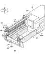
- FIG. 2 is a perspective view of the right rear telescopic screed 31R.
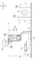
- FIG. 3 is a side view of the right rear telescopic screed 31R when the right rear telescopic screed 31R is viewed from the ⁇ Y side (right side). However, in FIG. 3, the illustration of the right side plate 40R is omitted for clarity. The following description regarding the right rear telescopic screed 31R also applies to the left rear telescopic screed 31L.
- the right rear telescopic screed 31R mainly includes a shaft cover UF, a guide shaft GS, a strike-off 33, and a screed plate 35, as shown in FIGS. Then, the -Z side portion (bottom portion) of the right rear telescopic screed 31R is mainly composed of a strike-off 33 and a screed plate 35 as shown in FIG.
- the shaft cover UF is a member that constitutes the upper end of the right rear telescopic screed 31R.
- the shaft cover UF has a substantially rectangular parallelepiped shape, and is configured to cover an upper portion of the guide shaft GS.
- the guide shaft GS is configured to guide the expansion and contraction of the right rear telescopic screed 31R.
- the guide shaft GS includes an upper guide shaft GS1 and a lower guide shaft GS2.
- the strike-off 33 is a member for swallowing (pressing) the pavement material PV spread and spread by the screw SC and adjusted in amount by the right telescopic mold board 43R under the right rear telescopic screed 31R.
- the strike-off 33 extends over the entire length of the right rear telescopic screed 31R in the Y-axis direction (vehicle width direction).
- an inclined surface that is inclined with respect to the ⁇ Z side surface (bottom surface) of the screed plate 35 is provided at a lower portion thereof. The inclined surface of strike-off 33 and the bottom surface of screed plate 35 form a pavement material swallowing angle.
- the screed plate 35 is a member constituting the bottom of the rear telescopic screed 31 vibrated by the vibrator, and compacts the pavement material PV swallowed through between the roadbed RB and the strike-off 33.
- the screed plate 35 extends over the entire length of the rear telescopic screed 31 in the vehicle width direction.
- the operation box SB is a device used by a worker working behind the asphalt finisher 100 to operate the asphalt finisher 100.
- the operation box SB includes a lever switch, a push switch, a monitor, and the like (not shown), and the degree of expansion and contraction of the leveling cylinder 23, the degree of expansion and contraction of the rear-side telescopic screed 31, and the speed of dispensing the conveyor CV ( (Operating speed) and the like can be adjusted by an operator.
- the right front ribbon light E2R is a front edge (+ X side edge) of the upper surface of the substantially rectangular parallelepiped shaft cover UF constituting the right rear elastic screed 31R, and is disposed along the elastic direction (Y-axis direction).
- the right front ribbon light E2R has a configuration in which 15 LED light emitters are intermittently arranged at predetermined regular intervals. Each LED emitter has the same size. However, each LED light emitter may be intermittently arranged at unequal intervals, or may be arranged continuously so that each LED light emitter is connected in the expansion and contraction direction. Further, each LED light emitter may have a different size from each other.
- the right front ribbon light E2R may be configured by one elongated LED light emitter. The same applies to the left front ribbon light E2L.
- Right front ribbon light E2R may be configured to emit light of any emission color.
- the right front ribbon light E2R is configured to emit light in the same emission color as the right side light W3R.
- the right front ribbon light E2R may be configured to emit light of a different emission color from the right side light W3R. The same applies to the left front ribbon light E2L.
- the right front ribbon light E2R may be arranged on the front surface (the surface on the + X side) of the shaft cover UF, or may be arranged on the front edge of the lower surface of the shaft cover UF.
- the right front ribbon light E2R may be arranged on another member (preferably, an elongated member extending in the expansion and contraction direction) of the right rear elastic screed 31R. The same applies to the left front ribbon light E2L.
- the right front ribbon light E2R is desirably disposed at a relatively high position so that the worker or the like does not hide behind other members when viewed from the front side (+ X side).
- the height H1 of the right front ribbon light E2R from the ground is higher than the height H2 of the right retaining plate 42R from the ground, and the ground of the right telescopic mold board 43R. Higher than the height H3. The same applies to the left front ribbon light E2L.
- the right rear ribbon light E3R is arranged along the direction of expansion and contraction (Y-axis direction) at the rear edge (the -X side edge) of the upper surface of the shaft cover UF of the right rear telescopic screed 31R.
- the right rear ribbon light E3R similarly to the right front ribbon light E2R, has a configuration in which 15 LED light emitters are intermittently arranged at predetermined regular intervals. Each LED emitter has the same size. However, each LED light emitter may be intermittently arranged at unequal intervals, or may be arranged continuously so that each LED light emitter is connected in the expansion and contraction direction. Further, each LED light emitter may have a different size from each other. Further, the right rear ribbon light E3R may be formed of one elongated LED light emitter. The same applies to the left rear ribbon light E3L.
- the right rear ribbon light E3R may be configured to emit light of an arbitrary emission color.
- the right rear ribbon light E3R is configured to emit light in the same emission color as the right backlight W4R.
- the right rear ribbon light E3R may be configured to emit light of a different emission color from the right backlight W4R. The same applies to the left rear ribbon light E3L.
- the right rear ribbon light E3R may be disposed on the rear surface (the surface on the ⁇ X side) of the shaft cover UF, or may be disposed on the rear edge of the lower surface of the shaft cover UF. Further, the right rear ribbon light E3R may be arranged on another member (preferably, an elongated member extending in the expansion and contraction direction) constituting the right rear telescopic screed 31R. The same applies to the left rear ribbon light E3L.
- the right rear ribbon light E3R is arranged at a relatively high position so that the work light does not hide behind other members when viewed from the back side ( ⁇ X side).
- the height H4 of the right rear ribbon light E3R from the ground is higher than the height H5 of the right step 32R from the ground, as shown in FIG. The same applies to the left rear ribbon light E3L.
- both the right front ribbon light E2R and the right rear ribbon light E3R are attached to the right rear telescopic screed 31R so as not to prevent the right rear telescopic screed 31R from being stored in the screed cover 3C. Therefore, in the present embodiment, the right front ribbon light E2R and the right rear ribbon light E3R are configured to be housed in the screed cover 3C together with the right rear telescopic screed 31R. That is, the caution light E3 as a light emitting unit is configured to be housed in the screed cover 3C when the rear-side telescopic screed 31 is in a contracted state.
- the right front ribbon light E2R and the right rear ribbon light E3R may be configured to be easily detachable from the right rear telescopic screed 31R.
- each LED light emitter may be configured to be easily detachable.
- the right front ribbon light E2R and the right rear ribbon light E3R may be removed from the right rear telescopic screed 31R when the right rear telescopic screed 31R is stored in the screed cover 3C.
- the asphalt finisher 100 includes the tractor 1, a protruding portion that protrudes from the width of the tractor 1, and a light emitting unit that is continuously or intermittently disposed in the protruding portion.
- the protruding portion is, for example, the hopper 2, the rear-side telescopic screed 31, the telescopic mold board 43, or the like.
- the light emitting units are, for example, caution lights E1 to E3.
- the asphalt finisher 100 can improve the visibility of a portion protruding from the width of the tractor 1. Therefore, a person who looks at the asphalt finisher 100 from the outside can easily confirm the presence of the protruding portion such as the hopper 2, the rear-side telescopic screed 31, or the telescopic mold board 43 even at night. As a result, the asphalt finisher 100 can enhance the work safety.
- the caution lights E2 and E3 as light emitting units are desirably arranged continuously or intermittently along the direction in which the rear telescopic screed 31 expands and contracts.
- the protruding portion may be a rear telescopic screed 31 that can expand and contract in the vehicle width direction.
- the caution lights E2 and E3 as light emitting units may be arranged so as to illuminate the front space and the rear space of the rear telescopic screed 31.
- the asphalt finisher 100 can illuminate the front space and the rear space of the rear telescopic screed 31 brighter than when illuminating only with the work lights W3 and W4.
- an operator working around the asphalt finisher 100 can easily check the amount of the pavement material PV held around the screw SC even at night.
- the protruding portion may be a telescopic mold board 43 that can expand and contract in the vehicle width direction.
- the light emitting unit may be continuously or intermittently arranged on the elastic mold board 43 along the elastic direction of the elastic mold board 43. With this configuration, the asphalt finisher 100 can improve the visibility of the stretch mold board 43.
- the protruding portion may be a hopper 2 that can be opened and closed in the vehicle width direction.
- the protruding portion may be a hopper wing 2W that can be opened and closed in the vehicle width direction.
- the caution light E1 as a light emitting unit may be arranged continuously or intermittently along the end face of the hopper wing 2W. With this configuration, the asphalt finisher 100 can improve the visibility of the hopper 2.
- the asphalt finisher 100 typically includes work lights W1 to W4. Therefore, the caution lights E1 to E3 as the light emitting units may be configured to be turned on when the work lights W1 to W4 are turned on. With this configuration, the operator can reliably turn on the attention lights E1 to E3 when turning on the work lights W1 to W4. For this reason, forgetting to turn on the caution lights E1 to E3 during nighttime work can be reliably prevented.
- the light emitting unit includes the caution light E1 installed along the end surface of the edge of the hopper wing 2W and the caution light E2 installed along the front edge of the upper surface of the rear telescopic screed 31. And a caution light E3 installed along the rear edge of the upper surface of the rear telescopic screed 31.
- the light emitting unit may include a caution light arranged before and after the screed cover 3C.
- the light emitting unit may include a caution light provided along a front edge of the upper surface of the screed cover 3C and a caution light provided along a rear edge of the upper surface of the screed cover 3C.
Landscapes
- Engineering & Computer Science (AREA)
- Mechanical Engineering (AREA)
- Architecture (AREA)
- Civil Engineering (AREA)
- Structural Engineering (AREA)
- Road Paving Machines (AREA)
Abstract
アスファルトフィニッシャ(100)は、トラクタ(1)と、トラクタ(1)の幅からはみ出すはみ出し部としての後側伸縮スクリード(31)と、後側伸縮スクリード(31)の伸縮方向に沿って連続的に或いは断続的に配置される発光部としての注意灯(E2)及び注意灯(E3)と、を備えている。注意灯(E2)は、後側伸縮スクリード(31)の前側の空間を照らすように配置されていてもよい。
Description
本開示は、アスファルトフィニッシャに関する。
従来、照明設備を備えたアスファルトフィニッシャが知られている(特許文献1参照。)。この照明設備は、夜間作業の際に作業箇所を照射できるように構成されている。
しかしながら、上述の照明設備は、バケット及びスクリード等のようなトラクタの幅からはみ出す部分を照射するようには構成されていない。そのため、トラクタの幅からはみ出す部分は、周囲から見えにくいおそれがある。
そこで、トラクタの幅からはみ出す部分の視認性を向上できるアスファルトフィニッシャの提供が望まれる。
本発明の実施形態に係るアスファルトフィニッシャは、トラクタと、前記トラクタの幅からはみ出すはみ出し部と、前記はみ出し部に連続的に或いは断続的に配置される発光部と、を備える。
上述の手段により、トラクタの幅からはみ出す部分の視認性を向上させるアスファルトフィニッシャが提供される。
図1A~図1Cは、本発明の実施形態に係る道路機械の一例であるアスファルトフィニッシャ100を示す。具体的には、図1Aはアスファルトフィニッシャ100の側面図であり、図1B及び図1Cはアスファルトフィニッシャ100の上面図である。図1Bにおける最も粗いドットパターンAPは既設舗装体等の表面を示し、クロスパターンNPは新設舗装体を示す。
アスファルトフィニッシャ100は、主に、トラクタ1、ホッパ2、及びスクリード3で構成されている。以下では、トラクタ1から見たホッパ2の方向(+X方向)を前方とし、トラクタ1から見たスクリード3の方向(-X方向)を後方とする。
トラクタ1は、アスファルトフィニッシャ100を走行させるための機構である。本実施形態では、トラクタ1は、後輪走行用モータを用いて後輪5を回転させ、且つ、前輪走行用モータを用いて前輪6を回転させてアスファルトフィニッシャ100を移動させる。後輪走行用モータ及び前輪走行用モータは油圧ポンプから作動油の供給を受けて回転する。後輪5及び前輪6はクローラで置き換えられてもよい。
コントローラ50は、アスファルトフィニッシャ100を制御する制御装置である。本実施形態では、コントローラ50は、CPU、揮発性記憶装置、及び不揮発性記憶装置を含む演算処理装置で構成され、トラクタ1に搭載されている。コントローラ50の各種機能は、不揮発性記憶装置に格納されたプログラムをCPUが実行することで実現される。
ホッパ2は、舗装材を受け入れるための機構である。本実施形態では、ホッパ2は、トラクタ1の前側に設置され、ホッパウイング2Wを含む。ホッパウイング2Wは、ホッパシリンダ24によってY軸方向(車幅方向)に開閉可能となるように構成されている。
具体的には、ホッパウイング2Wは、左ホッパウイング2WL及び右ホッパウイング2WRを含み、ホッパシリンダ24は、左ホッパシリンダ24L及び右ホッパシリンダ24Rを含む。そして、左ホッパウイング2WLは、左ホッパシリンダ24LによってY軸方向(車幅方向)に開閉可能となるように構成され、右ホッパウイング2WRは、右ホッパシリンダ24RによってY軸方向(車幅方向)に開閉可能となるように構成されている。ホッパウイング2Wが開くと、トラクタ1の幅(Y軸方向長さ)からホッパウイング2Wがはみ出すため、アスファルトフィニッシャ100の幅(Y軸方向長さ)は大きくなる。
アスファルトフィニッシャ100は、通常、ホッパウイング2Wを全開状態にしてダンプトラックの荷台から舗装材(例えばアスファルト混合物である。)を受け入れる。図1A~図1Cは、ホッパウイング2Wの全開状態を示している。ホッパ2内の舗装材が減少するとホッパウイング2Wが閉じられ、ホッパウイング2Wの内壁付近にあった舗装材がホッパ2の中央部に集められる。ホッパ2の中央部にあるコンベアCVがトラクタ1の後側に舗装材を給送できるようにするためである。トラクタ1の後側に給送された舗装材は、スクリュSCによってトラクタ1の後側且つスクリード3の前側で車幅方向に敷き拡げられる。本実施形態では、スクリュSCは、エクステンションスクリュが左右に連結された状態にある。
スクリード3は、舗装材を敷き均すための機構である。本実施形態では、スクリード3は、主に、前側スクリード30、及び、後側伸縮スクリード31を含む。スクリード3は、トラクタ1によって牽引される浮動スクリードであり、レベリングアーム3Aを介してトラクタ1に連結されている。スクリード3は、スクリードリフトシリンダ25の伸縮によってレベリングアーム3Aと共に上下動される。
前側スクリード30は左前側スクリード30L及び右前側スクリード30Rを含み、後側伸縮スクリード31は左後側伸縮スクリード31L及び右後側伸縮スクリード31Rを含む。左後側伸縮スクリード31Lはスクリード伸縮シリンダ26Lを用いて車幅方向に伸縮され、右後側伸縮スクリード31Rはスクリード伸縮シリンダ26Rを用いて車幅方向に伸縮される。後側伸縮スクリード31が伸長すると、トラクタ1の幅(Y軸方向長さ)から後側伸縮スクリード31がはみ出すため、アスファルトフィニッシャ100の幅(Y軸方向長さ)は大きくなる。
舗装体を締め固めるため、左前側スクリード30Lは左前側バイブレータ27Lによって振動させられ、右前側スクリード30Rは右前側バイブレータ27Rによって振動させられる。同様に、左後側伸縮スクリード31Lは左後側バイブレータ28Lによって振動させられ、右後側伸縮スクリード31Rは右後側バイブレータ28Rによって振動させられる。
レベリングシリンダ23は、アスファルト混合物の敷き均し厚さを調整するためにレベリングアーム3Aの前端部分を上下動させる油圧シリンダである。
スクリード3の端部にはサイドプレート40が取り付けられている。サイドプレート40は、スクリュSCによって敷き拡げられる舗装材PVの車幅方向への過度の拡がりを制限する。図1A及び図1Bは、スクリュSCによって敷き拡げられる舗装材PVを細かいドットパターンで示している。サイドプレート40は、右後側伸縮スクリード31Rから前方に延びる右サイドプレート40Rと、左後側伸縮スクリード31Lから前方に延びる左サイドプレート40Lとを含む。
トラクタ1の側部にはリテーニングプレート42が取り付けられている。リテーニングプレート42は、スクリュSCの回転によってトラクタ1(特に後輪5)の近傍で舗装材PVが前方に飛び散るのを防止する。本実施形態では、リテーニングプレート42は、トラクタ1の右側面に取り付けられる右リテーニングプレート42Rと、トラクタ1の左側面に取り付けられる左リテーニングプレート42Lとを含む。左リテーニングプレート42Lは、トラクタ1の左側面に回動可能(折り畳み可能)に取り付けられている。右リテーニングプレート42Rについても同様である。
スクリード3の前部には伸縮モールドボード43が取り付けられている。伸縮モールドボード43は、スクリード3の前方に滞留する舗装材PVの量を調整するための機構である。本実施形態では、伸縮モールドボード43は、不図示の油圧アクチュエータにより、後側伸縮スクリード31の伸縮に合わせて伸縮するように構成されている。舗装材PVは、伸縮モールドボード43の下端と路盤RBとの間の隙間を通ってスクリード3の下に至る。本実施形態では、伸縮モールドボード43は、右後側伸縮スクリード31Rの前方に取り付けられた右伸縮モールドボード43Rと、左後側伸縮スクリード31Lの前方に取り付けられた左伸縮モールドボード43Lとを含む。左伸縮モールドボード43Lは、左サイドプレート40L及び左後側伸縮スクリード31Lとは無関係に、Z軸方向に高さ調節ができるように構成されている。左伸縮モールドボード43Lを上下に移動させることで、左後側伸縮スクリード31Lの前方に滞留する舗装材の量を調整できるようにするためである。右伸縮モールドボード43Rについても同様である。
スクリード3の後部にはステップ32が取り付けられている。ステップ32は、作業者が利用できる踏み台である。本実施形態では、ステップ32は、前側スクリード30の後部に取り付けられた中央ステップ32Cと、右後側伸縮スクリード31Rの後部に取り付けられた右ステップ32Rと、左後側伸縮スクリード31Lの後部に取り付けられた左ステップ32Lとを含む。
アスファルトフィニッシャ100は、作業灯W1~W4を備えている。本実施形態では、作業灯W1~W4は、典型的には、トラクタ1に搭載された発電機12(オルタネータ)が発電した電力を用いて所定の空間を照らす。発電機12は、トラクタ1に搭載された駆動源としてのエンジン11によって駆動される。但し、作業灯W1~W4は、トラクタ1に搭載されたバッテリ等の蓄電池13の電力を用いて所定の空間を照らしてもよい。
本実施形態では、作業灯W1~W4は、LEDランプである。但し、作業灯W1~W4は、HIDランプ又はハロゲンランプ等であってもよい。作業灯W1~W4は、典型的には、スイッチSWによって点灯・消灯が切り換えられるように構成されている。スイッチSWは、典型的には、図1Aに示すように、運転席の前方に設置された操作パネルに含まれている。但し、スイッチSWは、スクリード3に設置された操作ボックスSB(図2参照。)等、アスファルトフィニッシャ100の他の部分に設けられていてもよい。作業灯W1~W4は、1つのスイッチSWによって点灯・消灯が切り換えられるように構成されていてもよく、別々のスイッチSWによって個別に点灯・消灯が切り換えられるように構成されていてもよい。
作業灯W1は、アスファルトフィニッシャ100の前方(進行方向)を照らす前照灯である。作業灯W1は、図1Bに示すように、トラクタ1の前端部の左端に設置された左ヘッドライトW1Lと、トラクタ1の前端部の右端に設置された右ヘッドライトW1Rと、を含む。
作業灯W2は、ホッパ2の内部を照らす。作業灯W2は、図1Bに示すように、トラクタ1の前端部の中央部に設置され、図1Cの粗いドットパターンで示すホッパ2の内側の範囲R1を照らす。
作業灯W3は、後側伸縮スクリード31の前方の空間を照らす。作業灯W3は、図1A及び図1Bに示すように、トラクタ1の側壁に設置されている。具体的には、作業灯W3は、左サイドライトW3L及び右サイドライトW3Rを含む。左サイドライトW3Lは、図1Cの粗いドットパターンで示す、左後側伸縮スクリード31Lの前方にある範囲R2を照らす。右サイドライトW3Rは、図1Cの粗いドットパターンで示す、右後側伸縮スクリード31Rの前方にある範囲R3を照らす。
作業灯W4は、後側伸縮スクリード31の後方の空間を照らす。作業灯W4は、図1A及び図1Bに示すように、キャノピCPの後端に設置されている。具体的には、作業灯W4は、左バックライトW4L及び右バックライトW4Rを含む。左バックライトW4Lは、図1Cの粗いドットパターンで示す、左後側伸縮スクリード31Lの後方にある範囲R4を照らす。右バックライトW4Rは、図1Cの粗いドットパターンで示す、右後側伸縮スクリード31Rの後方にある範囲R5を照らす。
アスファルトフィニッシャ100は、トラクタ1の幅からはみ出すはみ出し部に連続的に或いは断続的に配置される発光部を備えている。本実施形態では、はみ出し部は、ホッパ2、後側伸縮スクリード31、及び伸縮モールドボード43等を含む。発光部は、注意灯E1~E3を含む。
本実施形態では、注意灯E1~E3は、典型的には、作業灯W1~W4と同様に、発電機12(オルタネータ)が発電した電力を用いて発光する。但し、注意灯E1~E3は、トラクタ1に搭載された蓄電池13の電力を用いて発光してもよい。
注意灯E1~E3は、本実施形態では、LEDリボンライトである。但し、注意灯E1~E3は、フィラメントランプ又はキセノンランプ等であってもよい。注意灯E1~E3は、典型的には、作業灯W1~W4が点灯したときに点灯するように構成されている。本実施形態では、注意灯E1~E3は、スイッチSWによって作業灯W1~W4が点灯されたときに点灯し、スイッチSWによって作業灯W1~W4が消灯されたときに消灯するように構成されている。但し、注意灯E1~E3は、作業灯W1~W4とは無関係に点灯・消灯が切り換えられてもよい。例えば、注意灯E1~E3は、不図示の照度センサの出力に基づいて周囲が暗くなったと判断したときに自動的に点灯するように構成されていてもよい。
注意灯E1~E3のそれぞれは、常時点灯、同時点滅、又は順次点滅等、任意の点灯・点滅モードで発光するように構成されていてもよい。常時点灯は、例えば、注意灯E2を構成する複数のLED発光体の全てを継続的に点灯させる点灯モードを表す。同時点滅は、例えば、注意灯E2を構成する複数のLED発光体のそれぞれを同じタイミングで点滅させる点滅モードを表す。順次点滅は、注意灯E2を構成する複数のLED発光体のそれぞれを異なるタイミングで且つ所定の順番で点滅させる点滅モードを表す。点灯・点滅モードは、はみ出し部のはみ出し具合又ははみ出し速度等に応じて変化するように構成されていてもよい。はみ出し速度は、例えば、ホッパ2の開閉速度、後側伸縮スクリード31の伸縮速度、又は、伸縮モールドボード43の伸縮速度等を含む。
注意灯E1は、はみ出し部としてのホッパウイング2Wの視認性を高める発光部である。注意灯E1は、図1Bに示すように、左ホッパウイング2WLの縁部の端面に沿って設置された左リボンライトE1Lと、右ホッパウイング2WRの縁部の端面に沿って設置された右リボンライトE1Rと、を含む。左リボンライトE1Lは、信号線S1Lを介してコントローラ50に接続され、右リボンライトE1Rは、信号線S1Rを介してコントローラ50に接続されている。なお、注意灯E1は、ホッパウイング2Wの外壁の縁部に近い部分に設置されていてもよい。
この構成により、ホッパ2に舗装材を供給するダンプトラックの運転者は、夜間作業の際にアスファルトフィニッシャ100に向かって後進するとき、ホッパウイング2Wの開閉具合を容易に認識できる。また、施工中の道路に隣接する既設道路を走行する車両の運転者は、夜間走行中にアスファルトフィニッシャ100に前方(+X側)から接近するとき、ホッパウイング2Wの開閉具合を容易に認識できる。
注意灯E2は、はみ出し部としての後側伸縮スクリード31の前方からの視認性を高める発光部である。注意灯E2は、図1Bに示すように、左後側伸縮スクリード31Lの上面の前縁に沿って設置された左前リボンライトE2Lと、右後側伸縮スクリード31Rの上面の前縁に沿って設置された右前リボンライトE2Rと、を含む。左前リボンライトE2Lは、信号線S2Lを介してコントローラ50に接続され、右前リボンライトE2Rは、信号線S2Rを介してコントローラ50に接続されている。
左前リボンライトE2Lは、図1Cの細かいドットパターンで示す、左後側伸縮スクリード31Lの前方にある範囲R2Aを照らす。範囲R2Aは、範囲R2の一部である。右前リボンライトE2Rは、図1Cの細かいドットパターンで示す、右後側伸縮スクリード31Rの前方にある範囲R3Aを照らす。範囲R3Aは、範囲R3の一部である。
この構成により、施工中の道路に隣接する既設道路を走行する車両の運転者は、夜間走行中にアスファルトフィニッシャ100に前方(+X側)から接近するとき、後側伸縮スクリード31の伸縮具合を容易に認識できる。また、注意灯E2は、作業灯W3による照明を補助する補助灯としても機能し得る。
注意灯E3は、はみ出し部としての後側伸縮スクリード31の後方からの視認性を高める発光部である。注意灯E3は、図1Bに示すように、左後側伸縮スクリード31Lの上面の後縁に沿って設置された左後リボンライトE3Lと、右後側伸縮スクリード31Rの上面の後縁に沿って設置された右後リボンライトE3Rと、を含む。左後リボンライトE3Lは、信号線S3Lを介してコントローラ50に接続され、右後リボンライトE3Rは、信号線S3Rを介してコントローラ50に接続されている。
左後リボンライトE3Lは、図1Cの細かいドットパターンで示す、左後側伸縮スクリード31Lの後方にある範囲R4Aを照らす。範囲R4Aは、範囲R4の一部である。右後リボンライトE3Rは、図1Cの細かいドットパターンで示す、右後側伸縮スクリード31Rの後方にある範囲R5Aを照らす。範囲R5Aは、範囲R5の一部である。
この構成により、施工中の道路に隣接する既設道路を走行する車両の運転者は、夜間走行中にアスファルトフィニッシャ100に後方(-X側)から接近するとき、後側伸縮スクリード31の伸縮具合を容易に認識できる。また、注意灯E3は、作業灯W4による照明を補助する補助灯としても機能し得る。
次に、図2及び図3を参照し、後側伸縮スクリード31について説明する。図2は、右後側伸縮スクリード31Rの斜視図である。図3は、右後側伸縮スクリード31Rを-Y側(右側)から見たときの右後側伸縮スクリード31Rの側面図である。但し、図3は、明瞭化のため、右サイドプレート40Rの図示を省略している。右後側伸縮スクリード31Rに関する以下の説明は、左後側伸縮スクリード31Lにも適用される。
右後側伸縮スクリード31Rは、図2及び図3に示すように、主に、シャフトカバーUF、ガイドシャフトGS、ストライクオフ33、及びスクリードプレート35で構成されている。そして、右後側伸縮スクリード31Rの-Z側部分(底部)は、図3に示すように、主に、ストライクオフ33及びスクリードプレート35で構成されている。
シャフトカバーUFは、右後側伸縮スクリード31Rの上端部を構成する部材である。本実施形態では、シャフトカバーUFは、略直方体をなし、ガイドシャフトGSの上部を覆うように構成されている。
ガイドシャフトGSは、右後側伸縮スクリード31Rの伸縮を案内するように構成されている。本実施形態では、ガイドシャフトGSは、上側ガイドシャフトGS1及び下側ガイドシャフトGS2を含む。
ストライクオフ33は、スクリュSCによって敷き拡げられ且つ右伸縮モールドボード43Rによって量が調整された舗装材PVを右後側伸縮スクリード31Rの下に呑み込む(押し込む)ための部材である。本実施形態では、ストライクオフ33は、Y軸方向(車幅方向)における右後側伸縮スクリード31Rの全長にわたって延びる。また、スクリードプレート35の-Z側面(底面)に対して傾斜する傾斜面をその下部に備えている。ストライクオフ33の傾斜面とスクリードプレート35の底面は舗装材呑み込み角度を形成する。
スクリードプレート35は、バイブレータによって振動させられる後側伸縮スクリード31の底部を構成する部材であり、路盤RBとストライクオフ33の間を通って呑み込まれた舗装材PVを締め固める。本実施形態では、スクリードプレート35は、車幅方向における後側伸縮スクリード31の全長にわたって延びる。
操作ボックスSBは、アスファルトフィニッシャ100の後方で作業する作業者がアスファルトフィニッシャ100を操作するために用いる装置である。本実施形態では、操作ボックスSBは、不図示のレバースイッチ、プッシュスイッチ、及びモニタ等を含み、レベリングシリンダ23の伸縮具合、後側伸縮スクリード31の伸縮具合、及び、コンベアCVの撒き出し速度(動作速度)等を作業者が調節できるように構成されている。
右前リボンライトE2Rは、右後側伸縮スクリード31Rを構成する略直方体のシャフトカバーUFの上面の前縁(+X側の縁)で、伸縮方向(Y軸方向)に沿って配置されている。具体的には、右前リボンライトE2Rは、15個のLED発光体が所定の等間隔で断続的に配置された構成を有する。各LED発光体は、同じサイズを有する。但し、各LED発光体は、不等間隔で断続的に配置されていてもよく、伸縮方向において各LED発光体が繋がるように連続的に配置されていてもよい。また、各LED発光体は、互いに異なるサイズを有していてもよい。また、右前リボンライトE2Rは、1つの細長いLED発光体で構成されていてもよい。左前リボンライトE2Lについても同様である。
右前リボンライトE2Rは、任意の発光色で発光するように構成されていてもよい。本実施形態では、右前リボンライトE2Rは、右サイドライトW3Rと同じ発光色で発光するように構成されている。但し、右前リボンライトE2Rは、右サイドライトW3Rとは異なる発光色で発光するように構成されていてもよい。左前リボンライトE2Lについても同様である。
右前リボンライトE2Rは、シャフトカバーUFの前面(+X側の面)に配置されていてもよく、シャフトカバーUFの下面の前縁に配置されていてもよい。また、右前リボンライトE2Rは、右後側伸縮スクリード31Rを構成する他の部材(望ましくは伸縮方向に延びる細長い部材)に配置されていてもよい。左前リボンライトE2Lについても同様である。
右前リボンライトE2Rは、望ましくは、作業者等が正面側(+X側)から見たときに他の部材の陰に隠れてしまわないように、比較的高い位置に配置されている。本実施形態では、右前リボンライトE2Rの地面からの高さH1は、図3に示すように、右リテーニングプレート42Rの地面からの高さH2よりも高く、且つ、右伸縮モールドボード43Rの地面からの高さH3よりも高い。左前リボンライトE2Lについても同様である。
右後リボンライトE3Rは、右後側伸縮スクリード31RのシャフトカバーUFの上面の後縁(-X側の縁)で、伸縮方向(Y軸方向)に沿って配置されている。具体的には、右後リボンライトE3Rは、右前リボンライトE2Rと同様に、15個のLED発光体が所定の等間隔で断続的に配置された構成を有する。各LED発光体は、同じサイズを有する。但し、各LED発光体は、不等間隔で断続的に配置されていてもよく、伸縮方向において各LED発光体が繋がるように連続的に配置されていてもよい。また、各LED発光体は、互いに異なるサイズを有していてもよい。また、右後リボンライトE3Rは、1つの細長いLED発光体で構成されていてもよい。左後リボンライトE3Lについても同様である。
右後リボンライトE3Rは、任意の発光色で発光するように構成されていてもよい。本実施形態では、右後リボンライトE3Rは、右バックライトW4Rと同じ発光色で発光するように構成されている。但し、右後リボンライトE3Rは、右バックライトW4Rとは異なる発光色で発光するように構成されていてもよい。左後リボンライトE3Lについても同様である。
右後リボンライトE3Rは、シャフトカバーUFの後面(-X側の面)に配置されていてもよく、シャフトカバーUFの下面の後縁に配置されていてもよい。また、右後リボンライトE3Rは、右後側伸縮スクリード31Rを構成する他の部材(望ましくは伸縮方向に延びる細長い部材)に配置されていてもよい。左後リボンライトE3Lについても同様である。
右後リボンライトE3Rは、作業灯が背面側(-X側)から見たときに他の部材の陰に隠れてしまわないように、比較的高い位置に配置されている。本実施形態では、右後リボンライトE3Rの地面からの高さH4は、図3に示すように、右ステップ32Rの地面からの高さH5よりも高い。左後リボンライトE3Lについても同様である。
右前リボンライトE2R及び右後リボンライトE3Rは何れも、右後側伸縮スクリード31Rがスクリードカバー3C内に収納されるのを妨げないように、右後側伸縮スクリード31Rに取り付けられている。そのため、本実施形態では、右前リボンライトE2R及び右後リボンライトE3Rは、右後側伸縮スクリード31Rと共にスクリードカバー3C内に収納されるように構成されている。すなわち、発光部としての注意灯E3は、後側伸縮スクリード31が収縮状態の場合には、スクリードカバー3C内に収容されるように構成されている。但し、右前リボンライトE2R及び右後リボンライトE3Rは、右後側伸縮スクリード31Rに対して容易に着脱できるように構成されていてもよい。例えば、各LED発光体は、容易に着脱できるように構成されていてもよい。この場合、右前リボンライトE2R及び右後リボンライトE3Rは、右後側伸縮スクリード31Rがスクリードカバー3C内に収納される際に、右後側伸縮スクリード31Rから取り外されてもよい。左前リボンライトE2L及び左後リボンライトE3Lについても同様である。
上述のように、アスファルトフィニッシャ100は、トラクタ1と、トラクタ1の幅からはみ出すはみ出し部と、はみ出し部に連続的に或いは断続的に配置される発光部と、を備えている。はみ出し部は、例えば、ホッパ2、後側伸縮スクリード31、又は伸縮モールドボード43等である。発光部は、例えば、注意灯E1~E3等である。
この構成により、アスファルトフィニッシャ100は、トラクタ1の幅からはみ出す部分の視認性を向上させることができる。そのため、アスファルトフィニッシャ100を外から見ている者は、夜間であっても、ホッパ2、後側伸縮スクリード31、又は伸縮モールドボード43等のはみ出し部の存在を容易に確認できる。その結果、アスファルトフィニッシャ100は、作業に関する安全性を高めることができる。
発光部としての注意灯E2及びE3は、望ましくは、後側伸縮スクリード31の伸縮方向に沿って連続的に或いは断続的に配置されている。この構成により、アスファルトフィニッシャ100を外から見ている者は、後側伸縮スクリード31が車幅方向に連続的に延びていること、すなわち、アスファルトフィニッシャ100の本体に繋がっていることを容易に認識できる。そのため、この構成は、例えば、アスファルトフィニッシャ100を外から見ている者が、アスファルトフィニッシャ100の本体と後側伸縮スクリード31の端部との間に隙間(空間)が存在すると誤って認識してしまうのを防止できる。
はみ出し部は、車幅方向に伸縮可能な後側伸縮スクリード31であってもよい。この場合、発光部としての注意灯E2及びE3は、後側伸縮スクリード31の前側の空間及び後側の空間を照らすように配置されていてもよい。この構成により、アスファルトフィニッシャ100は、作業灯W3及びW4のみで照らす場合よりも、後側伸縮スクリード31の前側の空間及び後側の空間を明るく照らすことができる。その結果、例えば、アスファルトフィニッシャ100の周囲で作業する作業者は、夜間であっても、スクリュSCの周囲に抱え込まれている舗装材PVの量を容易に確認することができる。
はみ出し部は、車幅方向に伸縮可能な伸縮モールドボード43であってもよい。この場合、発光部は、伸縮モールドボード43の伸縮方向に沿って伸縮モールドボード43に連続的に或いは断続的に配置されていてもよい。この構成により、アスファルトフィニッシャ100は、伸縮モールドボード43の視認性を向上させることができる。
はみ出し部は、車幅方向に開閉可能なホッパ2であってもよい。具体的には、はみ出し部は、車幅方向に開閉可能なホッパウイング2Wであってもよい。この場合、発光部としての注意灯E1は、ホッパウイング2Wの端面に沿って連続的に或いは断続的に配置されていてもよい。この構成により、アスファルトフィニッシャ100は、ホッパ2の視認性を向上させることができる。
アスファルトフィニッシャ100は、典型的には、作業灯W1~W4を備えている。そのため、発光部としての注意灯E1~E3は、作業灯W1~W4が点灯したときに点灯するように構成されていてもよい。この構成により、操作者は、作業灯W1~W4を点灯させたときに、注意灯E1~E3を確実に点灯させることができる。そのため、夜間作業の際の注意灯E1~E3の点灯し忘れを確実に防止できる。
以上、本発明の好ましい実施形態が説明された。しかしながら、本発明は、上述した実施形態に限定されることはない。上述した実施形態は、本発明の範囲を逸脱することなしに、種々の変形又は置換等が適用され得る。また、上述の実施形態を参照して説明された特徴のそれぞれは、技術的に矛盾しない限り、適宜に組み合わされてもよい。
例えば、上述の実施形態では、発光部は、ホッパウイング2Wの縁部の端面に沿って設置された注意灯E1と、後側伸縮スクリード31の上面の前縁に沿って設置された注意灯E2と、後側伸縮スクリード31の上面の後縁に沿って設置された注意灯E3と、を含む。しかしながら、発光部は、スクリードカバー3Cの前後に配置される注意灯を含んでいてもよい。例えば、発光部は、スクリードカバー3Cの上面の前縁に沿って設置された注意灯と、スクリードカバー3Cの上面の後縁に沿って設置された注意灯と、を含んでいてもよい。
本願は、2018年8月3日に出願した日本国特許出願2018-146897号に基づく優先権を主張するものであり、この日本国特許出願の全内容を本願に参照により援用する。
1・・・トラクタ 2・・・ホッパ 2W・・・ホッパウイング 2WL・・・左ホッパウイング 2WR・・・右ホッパウイング 3・・・スクリード 3A・・・レベリングアーム 5・・・後輪 6・・・前輪 11・・・エンジン 12・・・発電機 13・・・蓄電池 23・・・レベリングシリンダ 24・・・ホッパシリンダ 25・・・スクリードリフトシリンダ 26L、26R・・・スクリード伸縮シリンダ 27L・・・左前側バイブレータ 27R・・・右前側バイブレータ 28L・・・左後側バイブレータ 28R・・・右後側バイブレータ 30・・・前側スクリード 31・・・後側伸縮スクリード 32・・・ステップ 33・・・ストライクオフ 35・・・スクリードプレート 40・・・サイドプレート 42・・・リテーニングプレート 43・・・伸縮モールドボード 50・・・コントローラ 100・・・アスファルトフィニッシャ CP・・・キャノピ CV・・・コンベア E1~E3・・・注意灯 PV・・・舗装材 RB・・・路盤 S1L、S1R、S2L、S2R、S3L、S3R・・・信号線 SC・・・スクリュ SW・・・スイッチ UF・・・シャフトカバー W1~W4・・・作業灯
Claims (9)
- トラクタと、
前記トラクタの幅からはみ出すはみ出し部と、
前記はみ出し部に連続的に或いは断続的に配置される発光部と、を備える、
アスファルトフィニッシャ。 - 前記はみ出し部は、車幅方向に伸縮可能な伸縮スクリードであり、
前記発光部は、前記伸縮スクリードの伸縮方向に沿って連続的に或いは断続的に配置されている、
請求項1に記載のアスファルトフィニッシャ。 - 前記発光部は、前記伸縮スクリードの前側の空間及び後側の空間を照らすように配置されている、
請求項2に記載のアスファルトフィニッシャ。 - 前記はみ出し部は、車幅方向に伸縮可能な伸縮モールドボードであり、
前記発光部は、前記伸縮モールドボードの伸縮方向に沿って前記伸縮モールドボードに連続的に或いは断続的に配置されている、
請求項1に記載のアスファルトフィニッシャ。 - 前記はみ出し部は、車幅方向に開閉可能なホッパであり、
前記発光部は、前記ホッパの端面に沿って連続的に或いは断続的に配置されている、
請求項1に記載のアスファルトフィニッシャ。 - 作業灯を備え、
前記発光部は、前記作業灯が点灯したときに点灯するように構成されている、
請求項1に記載のアスファルトフィニッシャ。 - 前記発光部は、前記伸縮スクリードが収縮状態の場合には、スクリードカバー内に収容されるように構成されている、
請求項2に記載のアスファルトフィニッシャ。 - 前記発光部は、前記スクリードカバーの前後に配置される、
請求項7に記載のアスファルトフィニッシャ。 - 前記発光部は、点滅するように構成されている、
請求項1に記載のアスファルトフィニッシャ。
Priority Applications (3)
| Application Number | Priority Date | Filing Date | Title |
|---|---|---|---|
| JP2020534765A JP7585787B2 (ja) | 2018-08-03 | 2019-08-02 | アスファルトフィニッシャ |
| CN201980044327.XA CN112368446A (zh) | 2018-08-03 | 2019-08-02 | 沥青滚平机 |
| EP19844096.8A EP3832018B1 (en) | 2018-08-03 | 2019-08-02 | Asphalt finisher |
Applications Claiming Priority (2)
| Application Number | Priority Date | Filing Date | Title |
|---|---|---|---|
| JP2018-146897 | 2018-08-03 | ||
| JP2018146897 | 2018-08-03 |
Publications (1)
| Publication Number | Publication Date |
|---|---|
| WO2020027313A1 true WO2020027313A1 (ja) | 2020-02-06 |
Family
ID=69231861
Family Applications (1)
| Application Number | Title | Priority Date | Filing Date |
|---|---|---|---|
| PCT/JP2019/030410 Ceased WO2020027313A1 (ja) | 2018-08-03 | 2019-08-02 | アスファルトフィニッシャ |
Country Status (4)
| Country | Link |
|---|---|
| EP (1) | EP3832018B1 (ja) |
| JP (1) | JP7585787B2 (ja) |
| CN (1) | CN112368446A (ja) |
| WO (1) | WO2020027313A1 (ja) |
Cited By (2)
| Publication number | Priority date | Publication date | Assignee | Title |
|---|---|---|---|---|
| JP2021131011A (ja) * | 2020-02-20 | 2021-09-09 | ヨゼフ フェゲーレ アーゲー | 作業領域の間接照明付きの路面仕上げ機 |
| JP2024021360A (ja) * | 2022-08-03 | 2024-02-16 | 日本道路株式会社 | 道路工事表示装置および道路工事箇所の表示方法 |
Citations (15)
| Publication number | Priority date | Publication date | Assignee | Title |
|---|---|---|---|---|
| JPH0660608U (ja) * | 1993-02-03 | 1994-08-23 | 範多機械株式会社 | アスファルトフィニッシャのホッパー |
| US5352063A (en) * | 1992-09-30 | 1994-10-04 | Allen Engineering Corporation | Polymer concrete paving machine |
| JPH074166U (ja) * | 1993-06-17 | 1995-01-20 | 株式会社アイチコーポレーション | 作業車の作業表示装置 |
| JPH0731907U (ja) * | 1993-04-09 | 1995-06-16 | 建設省東北地方建設局長 | 舗装作業車の自動操向装置 |
| JP2001138803A (ja) * | 1999-11-12 | 2001-05-22 | Shin Caterpillar Mitsubishi Ltd | 作業装置の車幅灯取付構造 |
| JP2002160575A (ja) * | 2000-11-28 | 2002-06-04 | Shinmeiwa Auto Engineering Ltd | 作業車両の警報装置 |
| JP2004116448A (ja) | 2002-09-27 | 2004-04-15 | Shin Caterpillar Mitsubishi Ltd | アスファルトフィニッシャのエンジン制御装置 |
| JP2004143894A (ja) * | 2002-10-21 | 2004-05-20 | Seki Kogyo Kk | 除雪用ブレードの車幅表示灯 |
| JP2006062545A (ja) * | 2004-08-27 | 2006-03-09 | Souji Kobayashi | 自動車のドア開放時の衝突事故防止装置 |
| JP2006290186A (ja) * | 2005-04-12 | 2006-10-26 | Shin Caterpillar Mitsubishi Ltd | 建設機械における照明装置の取り付け構造。 |
| JP2012241454A (ja) * | 2011-05-20 | 2012-12-10 | Sumitomo (Shi) Construction Machinery Co Ltd | スクリード装置の伸縮モールドボード上下調整機構 |
| JP2013079571A (ja) * | 2011-10-04 | 2013-05-02 | Joseph Voegele Ag | 建設機械用外部コントロールスタンド |
| JP2017166310A (ja) * | 2016-03-04 | 2017-09-21 | ヨゼフ フェゲーレ アーゲー | 側方に操作ユニットを有する道路仕上げ機 |
| JP2018146897A (ja) | 2017-03-08 | 2018-09-20 | 株式会社リコー | 電源装置及び画像形成装置 |
| JP2019002205A (ja) * | 2017-06-15 | 2019-01-10 | 範多機械株式会社 | アスファルトフィニッシャ |
Family Cites Families (5)
| Publication number | Priority date | Publication date | Assignee | Title |
|---|---|---|---|---|
| JPH0743133Y2 (ja) * | 1991-04-17 | 1995-10-04 | 株式会社新潟鉄工所 | アスファルトフィニッシャにおけるダンプカーの誘導装置 |
| DE102015008315A1 (de) | 2015-06-30 | 2017-01-05 | Dynapac Gmbh | Einbaubohle und Straßenfertiger |
| CN205951811U (zh) | 2016-08-19 | 2017-02-15 | 南京快联路桥建设工程有限公司 | 摊铺机照明结构 |
| CN206800131U (zh) * | 2017-06-08 | 2017-12-26 | 路敏 | 沥青路面热再生摊铺机 |
| CN207619871U (zh) * | 2017-12-12 | 2018-07-17 | 漆亮 | 一种太阳能建筑施工警示装置 |
-
2019
- 2019-08-02 WO PCT/JP2019/030410 patent/WO2020027313A1/ja not_active Ceased
- 2019-08-02 CN CN201980044327.XA patent/CN112368446A/zh active Pending
- 2019-08-02 JP JP2020534765A patent/JP7585787B2/ja active Active
- 2019-08-02 EP EP19844096.8A patent/EP3832018B1/en active Active
Patent Citations (15)
| Publication number | Priority date | Publication date | Assignee | Title |
|---|---|---|---|---|
| US5352063A (en) * | 1992-09-30 | 1994-10-04 | Allen Engineering Corporation | Polymer concrete paving machine |
| JPH0660608U (ja) * | 1993-02-03 | 1994-08-23 | 範多機械株式会社 | アスファルトフィニッシャのホッパー |
| JPH0731907U (ja) * | 1993-04-09 | 1995-06-16 | 建設省東北地方建設局長 | 舗装作業車の自動操向装置 |
| JPH074166U (ja) * | 1993-06-17 | 1995-01-20 | 株式会社アイチコーポレーション | 作業車の作業表示装置 |
| JP2001138803A (ja) * | 1999-11-12 | 2001-05-22 | Shin Caterpillar Mitsubishi Ltd | 作業装置の車幅灯取付構造 |
| JP2002160575A (ja) * | 2000-11-28 | 2002-06-04 | Shinmeiwa Auto Engineering Ltd | 作業車両の警報装置 |
| JP2004116448A (ja) | 2002-09-27 | 2004-04-15 | Shin Caterpillar Mitsubishi Ltd | アスファルトフィニッシャのエンジン制御装置 |
| JP2004143894A (ja) * | 2002-10-21 | 2004-05-20 | Seki Kogyo Kk | 除雪用ブレードの車幅表示灯 |
| JP2006062545A (ja) * | 2004-08-27 | 2006-03-09 | Souji Kobayashi | 自動車のドア開放時の衝突事故防止装置 |
| JP2006290186A (ja) * | 2005-04-12 | 2006-10-26 | Shin Caterpillar Mitsubishi Ltd | 建設機械における照明装置の取り付け構造。 |
| JP2012241454A (ja) * | 2011-05-20 | 2012-12-10 | Sumitomo (Shi) Construction Machinery Co Ltd | スクリード装置の伸縮モールドボード上下調整機構 |
| JP2013079571A (ja) * | 2011-10-04 | 2013-05-02 | Joseph Voegele Ag | 建設機械用外部コントロールスタンド |
| JP2017166310A (ja) * | 2016-03-04 | 2017-09-21 | ヨゼフ フェゲーレ アーゲー | 側方に操作ユニットを有する道路仕上げ機 |
| JP2018146897A (ja) | 2017-03-08 | 2018-09-20 | 株式会社リコー | 電源装置及び画像形成装置 |
| JP2019002205A (ja) * | 2017-06-15 | 2019-01-10 | 範多機械株式会社 | アスファルトフィニッシャ |
Non-Patent Citations (1)
| Title |
|---|
| See also references of EP3832018A4 |
Cited By (2)
| Publication number | Priority date | Publication date | Assignee | Title |
|---|---|---|---|---|
| JP2021131011A (ja) * | 2020-02-20 | 2021-09-09 | ヨゼフ フェゲーレ アーゲー | 作業領域の間接照明付きの路面仕上げ機 |
| JP2024021360A (ja) * | 2022-08-03 | 2024-02-16 | 日本道路株式会社 | 道路工事表示装置および道路工事箇所の表示方法 |
Also Published As
| Publication number | Publication date |
|---|---|
| EP3832018B1 (en) | 2024-12-18 |
| JPWO2020027313A1 (ja) | 2021-08-10 |
| EP3832018A1 (en) | 2021-06-09 |
| EP3832018A4 (en) | 2021-09-15 |
| CN112368446A (zh) | 2021-02-12 |
| JP7585787B2 (ja) | 2024-11-19 |
Similar Documents
| Publication | Publication Date | Title |
|---|---|---|
| CN103031800B (zh) | 用于建筑机械的外部控制台 | |
| JP5341465B2 (ja) | 車両用前照灯 | |
| WO2020027313A1 (ja) | アスファルトフィニッシャ | |
| DE112015000723T5 (de) | Scheinwerfersteuervorrichtung | |
| JP7257320B2 (ja) | アスファルトフィニッシャ | |
| EP3421669B1 (en) | Working machine | |
| DE69908365T2 (de) | Sicherheitspedal für fahrrad | |
| JP2025128272A (ja) | 照明設備を備える建設機械 | |
| JP6459305B2 (ja) | 車両用前照灯 | |
| JP2018044281A (ja) | 路面切削車両の安全監視装置 | |
| KR102673372B1 (ko) | 주변환경 적응적 조명 시스템 | |
| JP2023151437A (ja) | 道路機械 | |
| KR101911921B1 (ko) | 교통 신호 기능을 갖는 분리대 | |
| JP6503025B2 (ja) | 作業機 | |
| WO2023190355A1 (ja) | 道路機械 | |
| JP2024021360A (ja) | 道路工事表示装置および道路工事箇所の表示方法 | |
| KR101385160B1 (ko) | 헤드램프 | |
| JP6833276B2 (ja) | 灯具 | |
| JP6571722B2 (ja) | 作業機 | |
| JP3797978B2 (ja) | 道路作業用仮設交通信号機 | |
| KR101886783B1 (ko) | 자전거용 야간 보조 led 조명장치 | |
| JP2014168984A (ja) | 車両用前照灯装置 |
Legal Events
| Date | Code | Title | Description |
|---|---|---|---|
| 121 | Ep: the epo has been informed by wipo that ep was designated in this application |
Ref document number: 19844096 Country of ref document: EP Kind code of ref document: A1 |
|
| ENP | Entry into the national phase |
Ref document number: 2020534765 Country of ref document: JP Kind code of ref document: A |
|
| NENP | Non-entry into the national phase |
Ref country code: DE |
|
| ENP | Entry into the national phase |
Ref document number: 2019844096 Country of ref document: EP Effective date: 20210303 |