WO2020031501A1 - Dispositif manipulable et partie manipulable - Google Patents
Dispositif manipulable et partie manipulable Download PDFInfo
- Publication number
- WO2020031501A1 WO2020031501A1 PCT/JP2019/023538 JP2019023538W WO2020031501A1 WO 2020031501 A1 WO2020031501 A1 WO 2020031501A1 JP 2019023538 W JP2019023538 W JP 2019023538W WO 2020031501 A1 WO2020031501 A1 WO 2020031501A1
- Authority
- WO
- WIPO (PCT)
- Prior art keywords
- unit
- housing
- conductive
- operating
- supported
- Prior art date
- Legal status (The legal status is an assumption and is not a legal conclusion. Google has not performed a legal analysis and makes no representation as to the accuracy of the status listed.)
- Ceased
Links
Images


Classifications
-
- H—ELECTRICITY
- H01—ELECTRIC ELEMENTS
- H01H—ELECTRIC SWITCHES; RELAYS; SELECTORS; EMERGENCY PROTECTIVE DEVICES
- H01H3/00—Mechanisms for operating contacts
- H01H3/02—Operating parts, i.e. for operating driving mechanism by a mechanical force external to the switch
-
- H—ELECTRICITY
- H01—ELECTRIC ELEMENTS
- H01H—ELECTRIC SWITCHES; RELAYS; SELECTORS; EMERGENCY PROTECTIVE DEVICES
- H01H3/00—Mechanisms for operating contacts
- H01H3/02—Operating parts, i.e. for operating driving mechanism by a mechanical force external to the switch
- H01H3/04—Levers
-
- G—PHYSICS
- G06—COMPUTING OR CALCULATING; COUNTING
- G06F—ELECTRIC DIGITAL DATA PROCESSING
- G06F3/00—Input arrangements for transferring data to be processed into a form capable of being handled by the computer; Output arrangements for transferring data from processing unit to output unit, e.g. interface arrangements
- G06F3/01—Input arrangements or combined input and output arrangements for interaction between user and computer
- G06F3/03—Arrangements for converting the position or the displacement of a member into a coded form
- G06F3/033—Pointing devices displaced or positioned by the user, e.g. mice, trackballs, pens or joysticks; Accessories therefor
-
- H—ELECTRICITY
- H01—ELECTRIC ELEMENTS
- H01H—ELECTRIC SWITCHES; RELAYS; SELECTORS; EMERGENCY PROTECTIVE DEVICES
- H01H3/00—Mechanisms for operating contacts
- H01H3/02—Operating parts, i.e. for operating driving mechanism by a mechanical force external to the switch
- H01H3/08—Turn knobs
-
- H—ELECTRICITY
- H01—ELECTRIC ELEMENTS
- H01H—ELECTRIC SWITCHES; RELAYS; SELECTORS; EMERGENCY PROTECTIVE DEVICES
- H01H3/00—Mechanisms for operating contacts
- H01H3/02—Operating parts, i.e. for operating driving mechanism by a mechanical force external to the switch
- H01H3/12—Push-buttons
-
- H—ELECTRICITY
- H01—ELECTRIC ELEMENTS
- H01H—ELECTRIC SWITCHES; RELAYS; SELECTORS; EMERGENCY PROTECTIVE DEVICES
- H01H3/00—Mechanisms for operating contacts
- H01H3/02—Operating parts, i.e. for operating driving mechanism by a mechanical force external to the switch
- H01H2003/0293—Operating parts, i.e. for operating driving mechanism by a mechanical force external to the switch with an integrated touch switch
-
- H—ELECTRICITY
- H01—ELECTRIC ELEMENTS
- H01H—ELECTRIC SWITCHES; RELAYS; SELECTORS; EMERGENCY PROTECTIVE DEVICES
- H01H2239/00—Miscellaneous
- H01H2239/006—Containing a capacitive switch or usable as such
-
- H—ELECTRICITY
- H01—ELECTRIC ELEMENTS
- H01H—ELECTRIC SWITCHES; RELAYS; SELECTORS; EMERGENCY PROTECTIVE DEVICES
- H01H33/00—High-tension or heavy-current switches with arc-extinguishing or arc-preventing means
- H01H33/60—Switches wherein the means for extinguishing or preventing the arc do not include separate means for obtaining or increasing flow of arc-extinguishing fluid
- H01H33/66—Vacuum switches
- H01H33/664—Contacts; Arc-extinguishing means, e.g. arcing rings
- H01H33/6642—Contacts; Arc-extinguishing means, e.g. arcing rings having cup-shaped contacts, the cylindrical wall of which being provided with inclined slits to form a coil
-
- H—ELECTRICITY
- H01—ELECTRIC ELEMENTS
- H01H—ELECTRIC SWITCHES; RELAYS; SELECTORS; EMERGENCY PROTECTIVE DEVICES
- H01H33/00—High-tension or heavy-current switches with arc-extinguishing or arc-preventing means
- H01H33/60—Switches wherein the means for extinguishing or preventing the arc do not include separate means for obtaining or increasing flow of arc-extinguishing fluid
- H01H33/66—Vacuum switches
- H01H33/666—Operating arrangements
Definitions
- the present invention relates to an operation device and an operation unit.
- Patent Document 1 Conventionally, for example, in a game machine or an automobile, an operation device capable of performing a tilting operation using an operation lever has been used (for example, see Patent Document 1 below).
- the operating device has a housing having a conductive portion on a surface thereof, and the operating device is movably supported by the housing based on an operation by the operating body, and the operating device and the conductive portion are respectively And an operation unit capable of capacitively coupling, and a detection unit that detects a proximity state of the operation tool to the operation unit based on a change in capacitance in the conductive unit.
- the finger proximity circuit is not arranged on a movable portion such as a stick, it is possible to improve the degree of freedom in arranging members and extend the life.
- FIG. 3 is a cross-sectional view (first example) of the operation device according to the embodiment along the YZ plane. It is sectional drawing by the YZ plane (2nd example) of the operating device which concerns on one Embodiment. It is a block diagram showing the electric connection composition of the operation device concerning one embodiment.
- FIG. 2 is a block diagram illustrating a functional configuration of a control circuit according to one embodiment. It is sectional drawing of the push switch which concerns on 2nd Embodiment. It is a top view of the slide switch concerning a 3rd embodiment. It is a top view of the slide switch concerning a 3rd embodiment. It is sectional drawing of the rotary switch which concerns on 4th Embodiment.
- the Z-axis direction in the drawing is referred to as the up-down direction
- the X-axis direction in the drawing is referred to as the front-back direction
- the Y-axis direction in the drawing is referred to as the left-right direction.
- FIG. 1 is an external perspective view of an operation device 100 according to an embodiment.
- the operating device 100 illustrated in FIG. 1 is a device that allows the operating body 10 to tilt the operating lever 120 (an example of an “operating unit”).
- the operation device 100 is mounted on an operation target device 20 such as a game machine or an in-vehicle device, and is used for performing various application operations on the operation target device 20.
- the operation device 100 includes an operation lever 120 provided on an upper portion of a housing 110.
- the operating lever 120 can be tilted by the operating body 10 in the front-back direction (X-axis direction) and the left-right direction (Y-axis direction).
- the operator's finger is shown as the operating body 10, but the present invention is not limited to this.
- FIG. 2 is an exploded perspective view of the operation device 100 according to the embodiment.
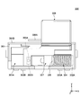
- FIGS. 3A and 3B are cross-sectional views (first and second examples) of the operating device 100 according to the embodiment along the YZ plane.
- the operating device 100 includes a housing 110, an operating lever 120, an encoder 132, an encoder 134, a substrate 135, and a control circuit 140.
- the housing 110 is a box-like member having a substantially rectangular parallelepiped shape.
- the housing 110 supports the operation lever 120 so that the operation lever 120 can be tilted.
- the surface (frame portion) of the housing 110 is formed of a conductive material (for example, a metal plate).
- a conductive material for example, a metal plate.
- the outer periphery of the housing 110 is surrounded by the operation knob 124 of the operation lever 120.
- the housing 110 can be capacitively coupled to the operation knob 124 on its surface.
- the operation lever 120 can be tilted in the front-rear direction (X-axis direction) and the left-right direction (Y-axis direction), and includes a shaft 122 and an operation knob 124.
- the shaft portion 122 is a bar-shaped member that stands upright in an opening 110 ⁇ / b> A formed on the upper surface of the housing 110.
- the shaft portion 122 is supported by the housing 110 so as to be tiltable in the front-rear direction (X-axis direction) and the left-right direction (Y-axis direction).
- a return means such as a spring.
- the operation knob 124 is attached to the tip of the shaft 122.
- the operation knob 124 is a member that can be attached to the shaft portion 122 to increase the contact area of the operation body 10 and enhance operability.
- the operation knob 124 is made of a relatively hard material (eg, resin, silicon, rubber, or the like).
- the operation knob 124 has an operation part 124A and an umbrella-shaped part 124B.
- the operation unit 124 ⁇ / b> A is a portion that is attached to the tip of the shaft unit 122, and on which a contact operation by the operation body 10 is performed.
- the operation section 124A has a substantially elliptical shape, but may have another shape (for example, a spherical shape or a flat shape).
- the umbrella-shaped portion 124B is a portion that extends outward and downward from the operation portion 124A in a curved manner along the outer periphery of the lower portion of the operation portion 124A.
- the umbrella-shaped portion 124 ⁇ / b> B has a shape close to the surface of the housing 110 and surrounding the outer periphery of the housing 110.
- a conductive layer 124C is formed on the surface of the operation knob 124.
- the conductive layer 124C can be formed by applying a conductive paint (for example, a paint containing carbon) on the surface of the operation knob 124.
- the operation knob 124 has an entire surface having conductivity, and can be capacitively coupled to each of the operation body 10 and the housing 110.
- the operation knob 124 can be capacitively coupled to the operation body 10 adjacent to the operation unit 124A at the operation unit 124A (“first capacitance coupling unit”).
- the operation knob 124 can be capacitively coupled to the surface of the housing 110 adjacent to the umbrella-shaped portion 124B at the umbrella-shaped portion 124B (“second capacitive coupling portion”).
- an insulating layer 124D (e.g., an elastomer) may be formed on the conductive layer 124C formed on the surface of the operation knob 124.
- the operation knob 124 itself may be a conductor, and the insulating layer 124 ⁇ / b> D may be formed on the surface of the operation knob 124.
- the operation knob 124 may not have the conductive layer 124C.
- the operation knob 124 can be capacitively coupled to each of the operation body 10 and the housing 110, and the insulating layer 124D formed on the surface of the operation knob 124 can stably detect capacitance coupling.
- the insulating layer 124D may cover the entire conductive layer 124C, or may cover only the region of the conductive layer 124C that is operated by the operating body.
- the encoder 132 and the encoder 134 are attached to the side surface of the housing 110.
- the encoder 132 detects an operation amount of the operation lever 120 in the X-axis direction (a rotation amount of the rotating shaft 112 that rotates in the X-axis direction) and outputs an operation signal (analog signal) corresponding to the operation amount in the X-axis direction. I do.
- the encoder 134 detects an operation amount of the operation lever 120 in the Y-axis direction (a rotation amount of the rotating shaft 114 rotating in the Y-axis direction) and outputs an operation signal (analog signal) corresponding to the operation amount in the Y-axis direction. I do.
- an optical rotary encoder is used as the encoder 132 and the encoder 134.
- the substrate 135 is a flat member on the upper surface of which the housing 110 and the control circuit 140 are mounted.
- a rigid substrate such as PWB (Printed Wired Board) or PCB (Printed Circuit Board) is used.
- the control circuit 140 is electrically connected to the surface of the housing 110 and each of the encoders 132 and 134 via wiring, metal terminals and the like (not shown).
- the control circuit 140 performs various controls of the operation device 100 (for example, driving of the surface of the housing 110, detection of capacitance on the surface of the housing 110, acquisition of operation signals from the encoders 132 and 134, and control of the operation target device 20). Output of operation signals, processing of operation signals, etc.).
- the control circuit 140 includes an IC (Integrated Circuit), a drive circuit, an AD (Analog Digital) converter, and the like in order to realize each function described later with reference to FIG.
- FIG. 4 is a block diagram illustrating an electrical connection configuration of the operating device 100 according to the embodiment.
- the operation knob 124 has a conductive layer 124 ⁇ / b> C on its surface, so that it can be capacitively coupled to the surface of the housing 110 and each of the operation bodies 10.
- the control circuit 140 is electrically connected to the surface of the housing 110 via wiring or the like. Thereby, the control circuit 140 can drive the surface of the housing 110 as a detection electrode by applying an AC voltage to the surface of the housing 110.
- control circuit 140 detects a current value corresponding to a change in the capacitance on the surface of the housing 110, and can determine the proximity state of the operating tool 10 based on the current value.
- control circuit 140 is electrically connected to the encoders 132 and 134 and the operation target device 20 via wiring and the like. Accordingly, the control circuit 140 receives the operation signals output from the encoders 132 and 134, performs various processes on the operation signals (for example, an analog-digital conversion process, a correction process of the operation position, and the like), and then performs the process. An operation signal can be output to the operation target device 20.
- FIG. 5 is a block diagram illustrating a functional configuration of the control circuit 140 according to the embodiment.
- the control circuit 140 includes a driving unit 142, an AD conversion unit 143, a detection unit 144, an acquisition unit 146, an AD conversion unit 147, and an output unit 154.
- the drive unit 142 drives the surface of the housing 110 as a detection electrode by applying an AC voltage to the surface of the housing 110.
- the AD conversion unit 143 converts an analog signal indicating a current value on the surface of the housing 110 driven by the driving unit 142 into a digital signal.
- the detecting unit 144 determines the proximity state of the operating tool 10 to the operating knob 124 based on a change in the current value (current value after AD conversion by the AD converting unit 143) on the surface of the housing 110 driven by the driving unit 142. To detect.
- the capacitance on the surface of the housing 110 changes when the proximity state of the operating tool 10 to the operation knob 124 changes, so that the capacitance on the surface of the housing 110 changes. I do.
- the detection unit 144 can detect the proximity state of the operation tool 10 to the operation knob 124 based on the current value on the surface of the housing 110.
- the detection unit 144 determines that the operating tool 10 is not close to the housing 110, and the current value on the surface of the housing 110 is equal to or more than the predetermined threshold th1. In the case of, it is determined that the operating tool 10 is close.
- the predetermined threshold value th1 for example, a suitable value capable of determining the proximity state of the operating tool 10 is stored in the memory in advance. The value of the predetermined threshold th1 may be changeable from an external information processing device.
- the acquisition unit 146 acquires operation signals (analog signals) corresponding to the operation of the operation lever 120 from the encoders 132 and 134. Specifically, the acquisition unit 146 acquires from the encoder 132 an operation signal corresponding to the operation amount of the operation lever 120 in the X-axis direction. Further, the acquisition unit 146 acquires an operation signal corresponding to the operation amount of the operation lever 120 in the Y-axis direction from the encoder 134.
- the AD conversion unit 147 converts the operation signal (analog signal) acquired by the acquisition unit 146 into a digital signal.
- the output unit 154 outputs an operation signal to the operation target device 20.
- the operation target device 20 can perform the operation of the operation target application with high accuracy based on the operation signal output from the output unit 154.
- the operating device 100 of the present embodiment is configured to make an electrical connection for capacitance detection to the surface of the housing 110 that is a fixed portion, instead of the operating lever 120 that is a movable portion. And thus, according to the operating device 100 of the present embodiment, the electrical connection in the manufacturing process can be performed relatively easily, and the durability of the electrical connection portion can be increased. Further, since the electrical connection member such as the wiring does not interfere with the movement of the operation lever 120, the operability of the operation lever 120 can be improved.
- the operating lever 120 can be capacitively coupled to the operating body 10 and the housing 110. Accordingly, the operating device 100 of the present embodiment can easily operate the operating lever 120 regardless of the shape or the material of the operating lever 120 and without changing the design of the shape and the material of the operating lever 120. And the housing 110 can be capacitively coupled.
- the operating device 100 of the present embodiment includes an operating portion 124A operated by the operating body 10 and an umbrella-shaped portion 124B extending downward from the operating portion 124A and surrounding the outer periphery of the housing 110. And thereby, the operation device 100 of the present embodiment can efficiently capacitively couple the operation knob 124 to both the operation body 10 and the housing 110 without increasing the number of components of the operation knob 124.
- the frame part forming the surface of the housing 110 is used as a conductive part for detecting capacitance.
- the operating device 100 of the present embodiment can detect a change in the capacitance of the housing 110 without increasing the number of components of the housing 110.
- the operation lever is not limited to the configuration described in the embodiment as long as it can be capacitively coupled to at least the operation body and the housing.
- the operation lever may be one in which the operation knob and the shaft are integrally formed.
- a conductive member for example, an electric wire
- the operation knob may be provided on the surface or inside instead of the conductive layer.
- the operation knob may be formed using a conductive material. In this case, since the operation knob has conductivity as a whole, it is not necessary to have a conductive layer on the surface.
- the conductivity is formed on the entire surface of the operation lever.
- the present invention is not limited to this.
- a conductive layer may be formed.
- the entire surface of the housing is defined as the “conductive portion” using a conductive material.
- the present invention is not limited to this, and a part of the surface of the housing may be formed of a conductive material. It may be used as a “conductive portion”.
- a metal plate may be attached to the surface of the housing, and this may be used as a “conductive portion”.
- the present invention is applied to the operation lever that can be tilted in both the X-axis direction and the Y-axis direction.
- the present invention is not limited to this, and the invention may be applied to either the X-axis direction or the Y-axis direction.
- the present invention is also applicable to an operation lever that can be tilted.
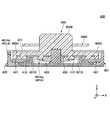
- FIG. 6 is a sectional view of a push switch 200 according to the second embodiment.
- the push switch 200 includes a housing 201, a pressing operation member 202, a rubber contact 203, fixed contacts 204A and 204B, and a movable contact 205.
- the housing 201 holds each component (the rubber contact 203 and the fixed contacts 204A and 204B).
- the surface of the housing 201 is covered with a conductive portion 201A formed using a conductive material (for example, a metal plate).
- Fixed contacts 204A and 204B are provided side by side at the center of the upper surface of the housing 201.
- the pressing operation member 202 is a member on which a pressing operation is performed by the operator.
- the pressing operation member 202 has an operation portion 202A, a flange portion 202B, and a side wall portion 202C.
- the operation unit 202A is a columnar part on which a pressing operation is performed by an operator.
- the operation unit 202A is fixed to the rubber contact 203 (the upper surface of the central part 203A) on the bottom surface.
- the flange portion 202B is a horizontal portion provided along the outer peripheral side surface of the operation portion 202A so as to expand outward from a lower end portion of the outer peripheral side surface.
- the side wall portion 202C is a wall-shaped portion provided along the outer peripheral edge of the flange portion 202B and hanging downward from the outer peripheral edge.
- the rubber contact 203 is provided on the upper surface of the housing 201.
- Rubber contact 203 has central portion 203A and leg portion 203B.
- the rubber contact 203 is formed using an elastic material such as rubber or silicon.
- the central portion 203A is a portion that moves up and down together with the pressing operation member 202 when the pressing operation member 202 is fixed to the upper surface thereof.
- a movable contact 205 is provided on the bottom surface of the central portion 203A.
- the central portion 203A is supported on its outer peripheral side surface by a leg portion 203B. When a pressing operation of the pressing operation member 202 is performed, the central portion 203A moves downward due to elastic deformation of the leg portion 203B.
- the central portion 203A can make the movable contact 205 conductive with each of the fixed contacts 204A and 204B.
- the pressing operation member 202 when no pressing operation is performed by the operator, the pressing operation member 202 is located at the initial position as shown in FIG. At this time, the movable contact 205 is separated from the fixed contacts 204A and 204B. Therefore, the push switch 200 is in an off state in which the fixed contact 204A and the fixed contact 204B are not electrically connected to each other.
- the push operation member 202 moves downward, and the leg portion 203B of the rubber contact 203 is elastically deformed. Move down. As a result, the movable contact 205 contacts the fixed contacts 204A and 204B. As a result, the push switch 200 is turned on, in which the fixed contact 204A and the fixed contact 204B are electrically connected to each other.
- the push switch 200 when the pressing operation by the operator is released, the push switch 200 returns the pressing operation member 202 to the initial position by the elastic return force of the leg portion 203B. Thus, the push switch 200 is turned off as shown in FIG. 6, in which the fixed contact 204A and the fixed contact 204B are not electrically connected to each other.
- the pressing operation member 202 has a side wall 202 ⁇ / b> C that is spaced apart from the side surface of the housing 201 by a certain distance and is provided in parallel with the side surface of the housing 301.
- the side wall portion 202C moves up and down on the side of the side surface of the housing 301 with the pressing operation of the pressing operation member 202.
- the pressing operation member 202 is formed using a conductive material (for example, a conductive resin) including the side wall portion 202C.
- the side surface of the housing 201 is covered with a conductive portion 201A formed using a material having conductivity.
- the push switch 200 can capacitively couple the pressing operation member 202 with each of the operating body (for example, the user's finger) and the side surface of the housing 201.
- the operation unit 202A corresponds to “a first capacitance coupling unit capable of capacitive coupling with the operation body”
- the side wall unit 202C has a “capacitive coupling with the conductive unit included in the housing”.
- Second capacitive coupling section ". Therefore, similarly to the first embodiment, the push switch 200 according to the second embodiment drives the side surface (the conductive portion 201A) of the housing 201 as a detection electrode to reduce the capacitance of the side surface of the housing 201.
- the proximity state of the operating tool can be determined based on the current value. Therefore, according to the push switch 200 according to the second embodiment, since the finger proximity circuit is not arranged on the pressing operation member 202 which is a movable portion, it is possible to improve the degree of freedom in the arrangement of members and extend the life.
- the push switch 200 the overlapping area of the side wall portion 202C and the conductive portion 201A changes according to the operation amount of the pressing operation member 202. Accordingly, the push switch 200 has a configuration in which the capacitance of the conductive portion 201A changes according to the operation amount of the pressing operation member 202.
- FIGS. 7A and 7B are plan views of the slide switch 300 according to the third embodiment.
- the slide switch 300 shown in FIGS. 7A and 7B is a so-called self-return type slide switch.
- the slide switch 300 includes a housing 301, fixed contacts 302A and 302B, connection terminals 303A and 303B, a coil spring 304, a movable contact 305, a holding member 307, and a slide operation member 308.
- the slide switch 300 includes a lid member (not shown) that covers an upper opening of the housing space 301A of the housing 301.
- FIGS. 7A and 7B the slide switch 300 with the lid member removed is illustrated. Is shown.
- the housing 301 houses and holds the components (fixed contacts 302A and 302B, connection terminals 303A and 303B, coil spring 304, movable contact 305, holding member 307, and slide operation member 308).
- the slide operation member 308 is provided to be slidable in the X-axis direction with respect to the housing 301 in accordance with a slide operation by an operator.
- the holding member 307 is provided in the housing space 301A of the housing 301 and holds the movable contact 305.
- the holding member 307 slides in the X-axis direction together with the slide operation member 308.
- the coil spring 304 is provided on the X-axis positive side of the holding member 307 so as to be elastically deformable in the X-axis direction.
- the coil spring 304 urges the holding member 307 and the slide operation member 308 toward the X axis negative side. Thereby, the coil spring 304 can return the slide operation member 308 to the initial position when the slide operation by the operator is released.
- the end on the X axis positive side of the coil spring 304 is in contact with the fixed contact 302A.
- An end on the X axis negative side of the coil spring 304 is in contact with the movable contact 305.
- the movable contact 305 is held by the holding member 307, and slides in the X-axis direction together with the holding member 307.
- the movable contact 305 is formed using a conductive material.
- the movable contact 305 is in contact with the end of the coil spring 304 on the negative side of the X axis, and is electrically connected to the fixed contact 302A via the coil spring 304.
- the movable contact 305 has a contact portion 305A below the holding member 307.
- the movable contact 305 is slid in the positive direction of the X-axis along with the sliding operation by the operator, so that the contact portion 305A is electrically connected to the fixed contact 302B (see FIG. 7B). As a result, the slide switch 300 is turned on.
- the movable contact 305 is slid in the negative direction of the X-axis with the release of the sliding operation by the operator, so that the conduction between the contact portion 305A and the fixed contact 302B is released (see FIG. 7A). As a result, the slide switch 300 is turned off.
- connection terminals 303A and 303B are provided on the side surface of the housing 301 and are connected to the outside (the target of the switch operation by the slide switch 300).
- the connection terminals 303A and 303B are formed using a conductive material.
- the connection terminal 303A is electrically connected to the fixed contact 302A.
- the connection terminal 303B is electrically connected to the fixed contact 302B.
- the fixed contact 302 ⁇ / b> A is provided in the housing space 301 ⁇ / b> A of the housing 301 in contact with the end of the coil spring 304 on the X axis positive side.
- the fixed contact 302B is provided below the holding member 307 in the housing space 301A of the housing 301.
- the fixed contacts 302A and 302B are formed using a conductive material.
- the slide operation member 308 when the operator does not perform the slide operation, the slide operation member 308 is located at the initial position by the urging force of the coil spring 304 as shown in FIG. 7A. At this time, the contact portion 305A of the movable contact 305 and the fixed contact 302B are not electrically connected to each other, so that the fixed contact 302A and the fixed contact 302B are not electrically connected to each other (ie, in an off state).
- the slide switch 300 slides the movable contact 305 along with the slide operation member 308 in the positive direction of the X axis.
- the contact portion 305A of the movable contact 305 and the fixed contact 302B conduct with each other, and thus the fixed contact 302A and the fixed contact 302B conduct with each other via the movable contact 305 and the coil spring 304 (ie, , ON state).
- the slide operation member 308 has a plate-shaped capacitive coupling portion 308A that is provided at a predetermined distance from the side surface of the housing 301 and is provided in parallel with the side surface of the housing 301. Further, the slide operation member 308 is formed using a conductive material (for example, a conductive resin) including the capacitive coupling portion 308A. Further, a conductive portion 301B having conductivity is provided on at least a side surface of the housing 301 facing the capacitive coupling portion 308A.
- the slide operation member 308 can be capacitively coupled to each of the operation body (for example, the user's finger) and the surface of the housing 301.
- the slide switch 300 drives the surface of the housing 301 (the conductive portion 301B) as a detection electrode, as in the first embodiment, to reduce the capacitance of the surface of the housing 301. By detecting a current value corresponding to the change, the proximity state of the operating tool can be determined based on the current value. Therefore, according to the slide switch 300 according to the third embodiment, since the finger proximity circuit is not disposed on the slide operation member 308 that is a movable portion, it is possible to improve the degree of freedom of member arrangement and extend the life.
- the slide switch 300 may have a configuration in which the overlapping area between the capacitive coupling unit 308A and the conductive unit 301B changes according to the operation amount of the slide operation member 308. Thereby, the slide switch 300 can be configured to change the capacitance of the conductive portion 301B according to the operation amount of the slide operation member 308.
- FIG. 8 is a sectional view of a rotary switch 400 according to the fourth embodiment.
- the rotary switch 400 includes a housing 401, a fixed contact 404, a connection terminal 405, a support shaft 406, a click plate 407, a movable contact 408, and a rotation operation member 409.
- the housing 401 houses and holds each component (fixed contact 404, connection terminal 405, support shaft 406, click plate 407, movable contact 408, and rotation operation member 409).
- An accommodation space 401A is formed inside the housing 401.
- the accommodation space 401A has an inner peripheral area 401Aa and an outer peripheral area 401Ab.
- An annular dustproof wall 401B is provided at the boundary between the inner peripheral area 401Aa and the outer peripheral area 401Ab in plan view.
- the upper opening of the accommodation space 401 is closed by a flat holding member 411.
- the holding member 411 is formed using a conductive material.
- the fixed contact 404 is provided at the bottom of the inner peripheral area 401Aa.
- the fixed contact 404 includes an annular common contact and a plurality of individual contacts arranged on the same circumference outside the common contact. Each of the common contact and the plurality of individual contacts is connected to a corresponding one of the plurality of connection terminals 405 exposed to the outside of the housing 401.
- the support shaft 406 is provided upright at the center of the bottom of the inner peripheral area 401Aa.
- the support shaft 406 rotatably supports the base 409A of the rotation operation member 409.
- the click plate 407 is an annular and flat member provided in the bottom of the outer peripheral area 401Ab in plan view.
- the click plate 407 is formed using a metal plate.
- the click plate 407 has a plurality of click generators formed side by side on the same circumference. Each of the plurality of click generators has an opening shape.
- the rotation operation member 409 has a base 409A arranged at the center of the accommodation space 401, and a cylindrical grip 409B provided to protrude upward from the center of the base 409A.
- the base 409A is rotatably supported by a support shaft 406.
- the grip portion 409B is a portion that protrudes from the upper surface of the housing 401 (the opening of the holding member 411) and that can be rotated by an operator.
- the rotation operation member 409 is formed using a resin material.
- the movable contact 408 is an annular member arranged in the inner peripheral area 401Aa and fixed to the bottom surface of the rotation operation member 409 (base 409A).
- the movable contact 408 includes a first slider that can slide while contacting the common contact of the fixed contact 404 and a second slider that can slide while sequentially contacting a plurality of individual contacts of the fixed contact 404. It is configured to have.
- the elastic member 410 is an annular member which is held by the rotation operating member 409 and is made of an elastic metal plate such as a stainless steel plate.
- the elastic member 410 has an engaging / disengaging portion projecting downward toward the click plate 407.
- the elastic member 410 rotates together with the rotation operation member 409.
- the engaging and disengaging portion of the elastic member 410 moves on the circumference of the click plate 407 to sequentially engage and disengage with a plurality of click generating portions formed side by side on the click plate 407.
- the elastic member 410 can give a click feeling to the rotation operation of the rotation operation member 409.
- the rotary switch 400 configured as described above, when the rotation operation of the rotation operation member 409 is performed by the operator, the movable contact 408 and the elastic member 410 rotate together with the rotation operation member 409. As a result, the common contact of the fixed contact 404 is sequentially connected to the plurality of individual contacts of the fixed contact 404 via the movable contact 408. At this time, the rotary switch 400 is configured to rotate and engage the elastic member 410 sequentially with a plurality of click generating portions arranged on the same circumference on the click plate 407 so that the rotating operation member 409 is rotated. Can be given a click feeling.
- the rotation operation member 409 has a capacitive coupling portion 409C.
- the capacitive coupling portion 409C is a horizontal and flat plate-shaped portion provided along the outer peripheral side surface of the grip portion 409B so as to expand outward from the outer peripheral side surface.
- the capacitive coupling portion 409C is separated from the holding member 411 forming the upper surface of the housing 401 by a certain distance, and is parallel to the holding member 411.
- the rotation operation member 409 is formed using a conductive material (for example, a conductive resin) including the capacitive coupling portion 409C.
- the holding member 411 configuring the upper surface of the housing 401 is formed using a conductive material (for example, a metal plate).
- the rotary operation member 409 can be capacitively coupled to each of the operating body (for example, a user's finger) and the holding member 411 configuring the upper surface of the housing 401.
- the grip portion 409B corresponds to “a first capacitive coupling portion capable of capacitive coupling with the operating body”
- the capacitive coupling portion 409C corresponds to “capacitive coupling with the conductive portion of the housing.
- the rotary switch 400 drives the upper surface of the housing 401 (the holding member 411) as a detection electrode, as in the first embodiment, to reduce the capacitance of the upper surface of the housing 401.
- the proximity state of the operating tool can be determined based on the current value. Therefore, according to the rotary switch 400 according to the fourth embodiment, since the finger proximity circuit is not arranged on the rotary operation member 409, which is a movable portion, it is possible to improve the degree of freedom of member arrangement and extend the life.
- the rotary switch 400 may have a configuration in which the overlapping area between the capacitive coupling portion 409C and the holding member 411 changes according to the operation amount of the rotary operation member 409.
- the rotary switch 400 can be configured to change the capacitance of the holding member 411 according to the operation amount of the rotation operation member 409.
Landscapes
- Engineering & Computer Science (AREA)
- General Engineering & Computer Science (AREA)
- Theoretical Computer Science (AREA)
- Human Computer Interaction (AREA)
- Physics & Mathematics (AREA)
- General Physics & Mathematics (AREA)
- Switches With Compound Operations (AREA)
- Switches That Are Operated By Magnetic Or Electric Fields (AREA)
- Rotary Switch, Piano Key Switch, And Lever Switch (AREA)
- Slide Switches (AREA)
- Switch Cases, Indication, And Locking (AREA)
- Push-Button Switches (AREA)
Abstract
Le dispositif manipulable est pourvu : d'un boîtier ayant des parties conductrices sur sa surface ; une unité manipulable supportée par le boîtier de manière à pouvoir se déplacer sur la base d'une manipulation par un corps manipulable et capable de couplage capacitif avec le corps manipulable et avec chacune des parties conductrices ; et une unité de détection pour détecter un état du corps manipulable à proximité de l'unité manipulable sur la base de changements des capacités électrostatiques au niveau des parties conductrices.
Priority Applications (3)
| Application Number | Priority Date | Filing Date | Title |
|---|---|---|---|
| CN201980052774.XA CN112602161A (zh) | 2018-08-08 | 2019-06-13 | 操作装置以及操作部 |
| JP2020536356A JP7286655B2 (ja) | 2018-08-08 | 2019-06-13 | 操作装置 |
| US17/165,123 US11424086B2 (en) | 2018-08-08 | 2021-02-02 | Operation device and operation member |
Applications Claiming Priority (2)
| Application Number | Priority Date | Filing Date | Title |
|---|---|---|---|
| JP2018149572 | 2018-08-08 | ||
| JP2018-149572 | 2018-08-08 |
Related Child Applications (1)
| Application Number | Title | Priority Date | Filing Date |
|---|---|---|---|
| US17/165,123 Continuation US11424086B2 (en) | 2018-08-08 | 2021-02-02 | Operation device and operation member |
Publications (1)
| Publication Number | Publication Date |
|---|---|
| WO2020031501A1 true WO2020031501A1 (fr) | 2020-02-13 |
Family
ID=69415465
Family Applications (1)
| Application Number | Title | Priority Date | Filing Date |
|---|---|---|---|
| PCT/JP2019/023538 Ceased WO2020031501A1 (fr) | 2018-08-08 | 2019-06-13 | Dispositif manipulable et partie manipulable |
Country Status (4)
| Country | Link |
|---|---|
| US (1) | US11424086B2 (fr) |
| JP (1) | JP7286655B2 (fr) |
| CN (1) | CN112602161A (fr) |
| WO (1) | WO2020031501A1 (fr) |
Cited By (2)
| Publication number | Priority date | Publication date | Assignee | Title |
|---|---|---|---|---|
| JP2022118534A (ja) * | 2021-02-02 | 2022-08-15 | オムロン株式会社 | トリガスイッチ |
| JPWO2023084976A1 (fr) * | 2021-11-15 | 2023-05-19 |
Families Citing this family (1)
| Publication number | Priority date | Publication date | Assignee | Title |
|---|---|---|---|---|
| TWI801056B (zh) * | 2021-12-23 | 2023-05-01 | 宏碁股份有限公司 | 旋鈕裝置 |
Citations (3)
| Publication number | Priority date | Publication date | Assignee | Title |
|---|---|---|---|---|
| JP2009218785A (ja) * | 2008-03-10 | 2009-09-24 | Toto Ltd | 静電容量式操作スイッチ及びそれを用いた水栓装置 |
| JP2011243399A (ja) * | 2010-05-18 | 2011-12-01 | Shin Etsu Polymer Co Ltd | スイッチ |
| JP2018073731A (ja) * | 2016-11-02 | 2018-05-10 | 池上通信機株式会社 | トグルスイッチ付き電子機器 |
Family Cites Families (6)
| Publication number | Priority date | Publication date | Assignee | Title |
|---|---|---|---|---|
| US7105762B1 (en) * | 2005-06-07 | 2006-09-12 | Eaton Corporation | Rocker switch and actuator therefor |
| JP2007173098A (ja) * | 2005-12-22 | 2007-07-05 | Alps Electric Co Ltd | 多方向スイッチ装置 |
| JP5993889B2 (ja) * | 2014-03-07 | 2016-09-14 | アルプス電気株式会社 | 静電容量式入力装置および静電容量式入力装置の製造方法 |
| JP2015191783A (ja) * | 2014-03-28 | 2015-11-02 | パナソニックIpマネジメント株式会社 | 入力装置 |
| CN106716580B (zh) * | 2014-11-10 | 2020-07-28 | 松下知识产权经营株式会社 | 输入装置 |
| US9804693B2 (en) | 2015-12-18 | 2017-10-31 | Oculus Vr, Llc | Handheld controller with activation sensors |
-
2019
- 2019-06-13 JP JP2020536356A patent/JP7286655B2/ja active Active
- 2019-06-13 CN CN201980052774.XA patent/CN112602161A/zh active Pending
- 2019-06-13 WO PCT/JP2019/023538 patent/WO2020031501A1/fr not_active Ceased
-
2021
- 2021-02-02 US US17/165,123 patent/US11424086B2/en active Active
Patent Citations (3)
| Publication number | Priority date | Publication date | Assignee | Title |
|---|---|---|---|---|
| JP2009218785A (ja) * | 2008-03-10 | 2009-09-24 | Toto Ltd | 静電容量式操作スイッチ及びそれを用いた水栓装置 |
| JP2011243399A (ja) * | 2010-05-18 | 2011-12-01 | Shin Etsu Polymer Co Ltd | スイッチ |
| JP2018073731A (ja) * | 2016-11-02 | 2018-05-10 | 池上通信機株式会社 | トグルスイッチ付き電子機器 |
Cited By (5)
| Publication number | Priority date | Publication date | Assignee | Title |
|---|---|---|---|---|
| JP2022118534A (ja) * | 2021-02-02 | 2022-08-15 | オムロン株式会社 | トリガスイッチ |
| JPWO2023084976A1 (fr) * | 2021-11-15 | 2023-05-19 | ||
| WO2023084976A1 (fr) * | 2021-11-15 | 2023-05-19 | アルプスアルパイン株式会社 | Dispositif d'entrée multidirectionnel |
| JP2025003725A (ja) * | 2021-11-15 | 2025-01-09 | アルプスアルパイン株式会社 | 多方向入力装置 |
| JP7783955B2 (ja) | 2021-11-15 | 2025-12-10 | アルプスアルパイン株式会社 | 多方向入力装置 |
Also Published As
| Publication number | Publication date |
|---|---|
| US11424086B2 (en) | 2022-08-23 |
| US20210159027A1 (en) | 2021-05-27 |
| CN112602161A (zh) | 2021-04-02 |
| JP7286655B2 (ja) | 2023-06-05 |
| JPWO2020031501A1 (ja) | 2021-08-10 |
Similar Documents
| Publication | Publication Date | Title |
|---|---|---|
| CN1447216B (zh) | 旋转操作型输入装置以及使用该装置的电子设备 | |
| US5613600A (en) | Rotatively-operated electronic component with push switch | |
| CN110506317B (zh) | 触摸面板用按钮结构、触摸面板用按钮以及电子设备 | |
| CN1133188C (zh) | 按压转动操作型电子装置及使用该装置的通讯终端设备 | |
| EP2755219B1 (fr) | Commutateur | |
| JP2011146297A (ja) | スイッチ機構並びに入力装置 | |
| JP2020514875A (ja) | 自動車用の操作装置 | |
| JP7286655B2 (ja) | 操作装置 | |
| CN1834879A (zh) | 轨迹球装置 | |
| JP2000003637A (ja) | 起倒スティック式指示装置 | |
| CN101815977A (zh) | 指尖触觉输入装置 | |
| JP2007123101A (ja) | 入力デバイス及び電子機器 | |
| CN117258273B (zh) | 电容摇杆、游戏手柄及游戏控制方法 | |
| JP4426209B2 (ja) | スライド入力キー | |
| CN119998769A (zh) | 用于电容式触摸屏的控制输入设备 | |
| KR20110048880A (ko) | 입력장치 | |
| KR101977054B1 (ko) | 자동차의 스위치 장치 | |
| CN112970086B (zh) | 输入装置 | |
| KR101514154B1 (ko) | 차량용 멀티 오퍼레이팅 스위치 유니트 | |
| JP4557599B2 (ja) | ポインティングデバイス及び端末装置 | |
| JP2013157106A (ja) | スイッチ装置 | |
| JP2006073249A (ja) | 携帯機器 | |
| TW202025195A (zh) | 具觸控螢幕之旋轉按壓開關 | |
| JP4063753B2 (ja) | ジョイスティック型入力装置 | |
| CN103824723B (zh) | 具有鼓轮和多个切换通道的增强的控制器件 |
Legal Events
| Date | Code | Title | Description |
|---|---|---|---|
| 121 | Ep: the epo has been informed by wipo that ep was designated in this application |
Ref document number: 19848337 Country of ref document: EP Kind code of ref document: A1 |
|
| ENP | Entry into the national phase |
Ref document number: 2020536356 Country of ref document: JP Kind code of ref document: A |
|
| NENP | Non-entry into the national phase |
Ref country code: DE |
|
| 122 | Ep: pct application non-entry in european phase |
Ref document number: 19848337 Country of ref document: EP Kind code of ref document: A1 |