WO2020031702A1 - Corps fritté à base de fe, procédé de production de corps fritté à base de fe et matrice de pressage à chaud - Google Patents
Corps fritté à base de fe, procédé de production de corps fritté à base de fe et matrice de pressage à chaud Download PDFInfo
- Publication number
- WO2020031702A1 WO2020031702A1 PCT/JP2019/029057 JP2019029057W WO2020031702A1 WO 2020031702 A1 WO2020031702 A1 WO 2020031702A1 JP 2019029057 W JP2019029057 W JP 2019029057W WO 2020031702 A1 WO2020031702 A1 WO 2020031702A1
- Authority
- WO
- WIPO (PCT)
- Prior art keywords
- sintered body
- based sintered
- sintering
- matrix
- phase
- Prior art date
- Legal status (The legal status is an assumption and is not a legal conclusion. Google has not performed a legal analysis and makes no representation as to the accuracy of the status listed.)
- Ceased
Links
Images

Classifications
-
- C—CHEMISTRY; METALLURGY
- C22—METALLURGY; FERROUS OR NON-FERROUS ALLOYS; TREATMENT OF ALLOYS OR NON-FERROUS METALS
- C22C—ALLOYS
- C22C33/00—Making ferrous alloys
- C22C33/02—Making ferrous alloys by powder metallurgy
- C22C33/0257—Making ferrous alloys by powder metallurgy characterised by the range of the alloying elements
- C22C33/0278—Making ferrous alloys by powder metallurgy characterised by the range of the alloying elements with at least one alloying element having a minimum content above 5%
- C22C33/0292—Making ferrous alloys by powder metallurgy characterised by the range of the alloying elements with at least one alloying element having a minimum content above 5% with more than 5% preformed carbides, nitrides or borides
-
- B—PERFORMING OPERATIONS; TRANSPORTING
- B22—CASTING; POWDER METALLURGY
- B22F—WORKING METALLIC POWDER; MANUFACTURE OF ARTICLES FROM METALLIC POWDER; MAKING METALLIC POWDER; APPARATUS OR DEVICES SPECIALLY ADAPTED FOR METALLIC POWDER
- B22F3/00—Manufacture of workpieces or articles from metallic powder characterised by the manner of compacting or sintering; Apparatus specially adapted therefor ; Presses and furnaces
- B22F3/10—Sintering only
- B22F3/105—Sintering only by using electric current other than for infrared radiant energy, laser radiation or plasma ; by ultrasonic bonding
-
- B—PERFORMING OPERATIONS; TRANSPORTING
- B22—CASTING; POWDER METALLURGY
- B22F—WORKING METALLIC POWDER; MANUFACTURE OF ARTICLES FROM METALLIC POWDER; MAKING METALLIC POWDER; APPARATUS OR DEVICES SPECIALLY ADAPTED FOR METALLIC POWDER
- B22F3/00—Manufacture of workpieces or articles from metallic powder characterised by the manner of compacting or sintering; Apparatus specially adapted therefor ; Presses and furnaces
- B22F3/004—Filling molds with powder
-
- B—PERFORMING OPERATIONS; TRANSPORTING
- B22—CASTING; POWDER METALLURGY
- B22F—WORKING METALLIC POWDER; MANUFACTURE OF ARTICLES FROM METALLIC POWDER; MAKING METALLIC POWDER; APPARATUS OR DEVICES SPECIALLY ADAPTED FOR METALLIC POWDER
- B22F3/00—Manufacture of workpieces or articles from metallic powder characterised by the manner of compacting or sintering; Apparatus specially adapted therefor ; Presses and furnaces
- B22F3/10—Sintering only
- B22F3/1039—Sintering only by reaction
-
- B—PERFORMING OPERATIONS; TRANSPORTING
- B22—CASTING; POWDER METALLURGY
- B22F—WORKING METALLIC POWDER; MANUFACTURE OF ARTICLES FROM METALLIC POWDER; MAKING METALLIC POWDER; APPARATUS OR DEVICES SPECIALLY ADAPTED FOR METALLIC POWDER
- B22F3/00—Manufacture of workpieces or articles from metallic powder characterised by the manner of compacting or sintering; Apparatus specially adapted therefor ; Presses and furnaces
- B22F3/12—Both compacting and sintering
- B22F3/14—Both compacting and sintering simultaneously
-
- B—PERFORMING OPERATIONS; TRANSPORTING
- B22—CASTING; POWDER METALLURGY
- B22F—WORKING METALLIC POWDER; MANUFACTURE OF ARTICLES FROM METALLIC POWDER; MAKING METALLIC POWDER; APPARATUS OR DEVICES SPECIALLY ADAPTED FOR METALLIC POWDER
- B22F5/00—Manufacture of workpieces or articles from metallic powder characterised by the special shape of the product
- B22F5/007—Manufacture of workpieces or articles from metallic powder characterised by the special shape of the product of moulds
-
- B—PERFORMING OPERATIONS; TRANSPORTING
- B22—CASTING; POWDER METALLURGY
- B22F—WORKING METALLIC POWDER; MANUFACTURE OF ARTICLES FROM METALLIC POWDER; MAKING METALLIC POWDER; APPARATUS OR DEVICES SPECIALLY ADAPTED FOR METALLIC POWDER
- B22F9/00—Making metallic powder or suspensions thereof
- B22F9/02—Making metallic powder or suspensions thereof using physical processes
- B22F9/04—Making metallic powder or suspensions thereof using physical processes starting from solid material, e.g. by crushing, grinding or milling
-
- C—CHEMISTRY; METALLURGY
- C22—METALLURGY; FERROUS OR NON-FERROUS ALLOYS; TREATMENT OF ALLOYS OR NON-FERROUS METALS
- C22C—ALLOYS
- C22C38/00—Ferrous alloys, e.g. steel alloys
-
- B—PERFORMING OPERATIONS; TRANSPORTING
- B22—CASTING; POWDER METALLURGY
- B22F—WORKING METALLIC POWDER; MANUFACTURE OF ARTICLES FROM METALLIC POWDER; MAKING METALLIC POWDER; APPARATUS OR DEVICES SPECIALLY ADAPTED FOR METALLIC POWDER
- B22F3/00—Manufacture of workpieces or articles from metallic powder characterised by the manner of compacting or sintering; Apparatus specially adapted therefor ; Presses and furnaces
- B22F3/10—Sintering only
- B22F3/105—Sintering only by using electric current other than for infrared radiant energy, laser radiation or plasma ; by ultrasonic bonding
- B22F2003/1051—Sintering only by using electric current other than for infrared radiant energy, laser radiation or plasma ; by ultrasonic bonding by electric discharge
-
- B—PERFORMING OPERATIONS; TRANSPORTING
- B22—CASTING; POWDER METALLURGY
- B22F—WORKING METALLIC POWDER; MANUFACTURE OF ARTICLES FROM METALLIC POWDER; MAKING METALLIC POWDER; APPARATUS OR DEVICES SPECIALLY ADAPTED FOR METALLIC POWDER
- B22F9/00—Making metallic powder or suspensions thereof
- B22F9/02—Making metallic powder or suspensions thereof using physical processes
- B22F9/04—Making metallic powder or suspensions thereof using physical processes starting from solid material, e.g. by crushing, grinding or milling
- B22F2009/043—Making metallic powder or suspensions thereof using physical processes starting from solid material, e.g. by crushing, grinding or milling by ball milling
-
- B—PERFORMING OPERATIONS; TRANSPORTING
- B22—CASTING; POWDER METALLURGY
- B22F—WORKING METALLIC POWDER; MANUFACTURE OF ARTICLES FROM METALLIC POWDER; MAKING METALLIC POWDER; APPARATUS OR DEVICES SPECIALLY ADAPTED FOR METALLIC POWDER
- B22F2301/00—Metallic composition of the powder or its coating
- B22F2301/35—Iron
-
- B—PERFORMING OPERATIONS; TRANSPORTING
- B22—CASTING; POWDER METALLURGY
- B22F—WORKING METALLIC POWDER; MANUFACTURE OF ARTICLES FROM METALLIC POWDER; MAKING METALLIC POWDER; APPARATUS OR DEVICES SPECIALLY ADAPTED FOR METALLIC POWDER
- B22F2302/00—Metal Compound, non-Metallic compound or non-metal composition of the powder or its coating
- B22F2302/05—Boride
-
- B—PERFORMING OPERATIONS; TRANSPORTING
- B22—CASTING; POWDER METALLURGY
- B22F—WORKING METALLIC POWDER; MANUFACTURE OF ARTICLES FROM METALLIC POWDER; MAKING METALLIC POWDER; APPARATUS OR DEVICES SPECIALLY ADAPTED FOR METALLIC POWDER
- B22F2998/00—Supplementary information concerning processes or compositions relating to powder metallurgy
- B22F2998/10—Processes characterised by the sequence of their steps
-
- B—PERFORMING OPERATIONS; TRANSPORTING
- B22—CASTING; POWDER METALLURGY
- B22F—WORKING METALLIC POWDER; MANUFACTURE OF ARTICLES FROM METALLIC POWDER; MAKING METALLIC POWDER; APPARATUS OR DEVICES SPECIALLY ADAPTED FOR METALLIC POWDER
- B22F2999/00—Aspects linked to processes or compositions used in powder metallurgy
Definitions
- the present invention relates to an Fe-based sintered body, a method for producing an Fe-based sintered body, and a mold for hot pressing.
- hot press technology has been used, for example, in the manufacture of automobile body parts.
- the steel sheet is heated (press forming) by pressing the steel sheet using a hot pressing mold in a heated state.
- the steel is hardened by quenching (quenching) during the press forming.
- Such a hot pressing technique has become an important technique for securing molding accuracy and strength after molding when manufacturing a product (part) using ultra-high tensile strength steel.
- the performance required of the hot press mold includes high durability (long life) and high cooling performance that can be used repeatedly.
- Patent Document 1 describes a technique for improving the thermal conductivity of tool steel at room temperature.
- SKD61 is known as a material for a hot press mold.
- This material has a hardness of about 50H R C in Rockwell hardness.
- the thermal conductivity of the material is about 24 W / (m ⁇ K), and further improvement of the thermal conductivity is required.
- Patent Document 1 describes a tool steel in which the internal structure of the steel is metallurgically defined to improve the thermal conductivity at room temperature. However, it is difficult to precisely control the internal structure of steel, and there is a problem that the tool steel is difficult to stably produce.
- the present invention has been made in view of the above situation, and has both high hardness and high thermal conductivity, and can be manufactured more stably. Material). Another object of the present invention is to provide a method for producing an Fe-based sintered body that can more stably produce an Fe-based sintered body having both high hardness and high thermal conductivity.
- an Fe-based sintered body is an Fe-based sintered body having a matrix containing Fe as a main component and a dispersed phase dispersed in the matrix.
- the matrix is formed in a network and contains ⁇ Fe, and the dispersed phase contains TiC.
- a method for manufacturing an Fe-based sintered body includes a step of forming a compact obtained by press-molding a mixed powder containing Fe powder and TiB 2 powder,
- the method includes a sintering step of heating and sintering while applying pressure using a graphite pressing member.
- the sintering step includes applying a pressure in a pressure range of 15 MPa or more and heating at a temperature of 1323 K or more.
- a network-like matrix containing Fe as a main component and Ti is formed, and the matrix contains ⁇ Fe, and Ti derived from TiB 2 and C derived from the pressing member. And sintering to produce TiC dispersed in the matrix.
- an Fe-based sintered body that has both high hardness and high thermal conductivity and can be manufactured more stably.
- a method for producing an Fe-based sintered body that can more stably produce an Fe-based sintered body having both high hardness and high thermal conductivity.
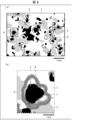
- FIG. 4 is a reflected electron image obtained by observing the material structure of the Fe-based sintered body according to one embodiment of the present invention using an electron microscope.
- (A) is a schematic diagram of the reflected electron image shown in FIG. 1, and (b) is an enlarged view of a part of the schematic diagram shown in (a).
- FIG. 2 is a backscattered electron image obtained by observing a sample polished so that the material structure of the Fe-based sintered body in one embodiment of the present invention can be observed, (a) is a sample surface, and (b) is a sample. It is a reflected electron image which observed the sample cross section.
- FIG. 3C is an enlarged view showing a diffraction angle 2 ⁇ of around 45 ° in the X-ray diffraction pattern shown in FIG. (A) is a figure which shows the location which performed local WDX in the reflection electron image of the sample produced on the conditions of the sintering temperature of 1373K, (b) is the composition analysis result of 8 places which performed WDX. It is a table shown.
- FIG. 3C is an enlarged view showing a diffraction angle 2 ⁇ of about 35 ° in the X-ray diffraction pattern in the X-ray diffraction pattern shown in FIG. 9 is a table collectively showing test results of each sample in a second example.
- (A) is a reflection electron image obtained by observing the material structure of a sample prepared with a mass ratio of pure Fe: TiB 2 of 80:20 using an electron microscope, and (b) is a reflection electron image of the sample. It is a table
- alloy tool steel for example, SKD61
- SKD61 has a specific chemical composition and is subjected to various heat treatments, thereby achieving desired performance.
- various microstructures are formed in steel. Such a microstructure acts to improve the hardness of the steel, while acting to hinder heat conduction.
- the higher the hardness of a substance the lower the electron conductivity and the phonon conductivity, so that the substance is inferior in thermal conductivity.
- Patent Document 1 discloses a technique for reducing the content of carbon and chromium in a steel matrix and improving the thermal conductivity of tool steel at room temperature by increasing the phonon conductivity of carbides as a dispersed phase. Has been described. However, it is not easy to stably control the internal structure of steel to a desired state because the internal structure of steel can be variously affected by the composition of components, heat treatment, and various other conditions. Absent.
- the present inventors have attempted to create a material that has both high hardness and high thermal conductivity and that can increase the stability of production by a different approach from the conventional one.
- the Fe-based sintered body produced by sintering a mixed powder of pure iron (Fe) and titanium boride (TiB 2 ) exhibits the following properties by adjusting the sintering conditions. I found that.
- a hard material containing TiC in the Fe-based sintered body A phase forms.
- This hard phase can be obtained by suitably finely dispersing it in an Fe matrix.
- the Fe matrix has a network-like structure (a network-like structure) and contains ⁇ Fe, and can suitably function as a heat conduction path.
- the thermal conductivity may decrease.
- the Fe-based sintered body according to one embodiment of the present invention is manufactured using iron having a low carbon content as a raw material, and in the manufacturing process, when TiB 2 is decomposed, Fe and C are bonded. Ti and C bond more easily to form TiC than to generate cementite. Therefore, in the present Fe-based sintered body, the production of cementite can be suppressed during production, and the content of cementite can be reduced.
- FIG. 1 is a reflected electron image obtained by observing the internal structure (material structure) of the Fe-based sintered body of the present embodiment using an electron microscope.
- the Fe-based sintered body of the present embodiment contains a matrix (matrix) 1 containing Fe as a main component and a dispersed phase containing various phases.
- the Fe-based sintered body of the present embodiment is generally formed (manufactured) by sintering a mixed powder of Fe and TiB 2 under a condition where C is supplied as described above. Therefore, the dispersed phase includes a particulate phase (first subphase) 2 containing TiB 2 as a raw material, and a hard phase 4 containing fine TiC generated by a reaction between TiB 2 and C.
- the dispersed phase further includes a by-product phase (second sub-phase) 3 containing Fe 2 B generated by a reaction between Fe and B supplied from TiB 2 .
- FIG. 2A is a schematic view of the backscattered electron image shown in FIG.
- FIG. 2B is an enlarged view of a part of the schematic diagram.
- the matrix 1 is shown as a region with the lightest shade (white)
- the particulate phase 2 is shown as a region with the darkest shade (black).
- the by-product phase 3 is shown as a region where the density is slightly darker (light gray) than the matrix 1
- the hard phase 4 is shown as a region where the density is between the by-product phase 3 and the particulate phase 2 (dark gray). Is shown.
- the matrix 1 is a phase having the largest proportion of the Fe-based sintered body and is formed in a network.
- the matrix 1 preferably accounts for 75% by mass or more, more preferably 60% by mass or more and 80% by mass or less, based on 100 parts by weight of the entire Fe-based sintered body. .
- the matrix 1 is a phase containing Fe as a main component, and the concentration of Fe in the matrix 1 is 99 atomic percent (hereinafter, referred to as at%) or more, and preferably 99.9 at% or more.
- Matrix 1 contains ⁇ Fe.
- the matrix 1 preferably consists for the most part of ⁇ Fe. When C atoms are dissolved in ⁇ Fe, ⁇ Fe in which C atoms are dissolved is also expressed as a ferrite phase.
- the network shape means that, when the material structure is viewed in a plan view (when a cross section is observed), for example, as shown in FIG. 2A, a network-like continuous phase is formed.
- the particulate phase 2, the by-product phase 3, and the hard phase 4 are dispersed in the form of islands in the interstices of the network in the network structure of the matrix 1, forming an island-like composite structure of the Fe-based sintered body.
- the matrix 1 since the matrix 1 is polycrystalline, a crystal grain boundary exists in a network-like structure (a network-like structure). Since the Fe-based sintered body is formed by sintering, the matrix 1 may have some voids (voids).
- the matrix 1 may have a concentration distribution and may have a plurality of phases. Such a matrix 1 has excellent thermal conductivity.
- FIG. 2 is a schematic view of the material structure in plan view, but in practice, the matrix 1 has a network-like structure in a three-dimensional space.
- the matrix 1 can function as a continuous path (heat conduction path) effective for heat conduction.
- the matrix 1 may have a cementite content of 5% by mass or less, preferably 1% by mass or less.
- the matrix 1 may have a content of ⁇ Fe of 70% by mass or more, and may be 60% by mass or more and 80% by mass or less. Further, ⁇ Fe is a ferrite phase, and a two-phase structure of the ferrite phase and cementite may be a layered structure, and it is preferable that cementite, which easily inhibits heat conduction, is in a localized state.
- the matrix 1 may satisfy at least one of the conditions of a Cu content of 0.1% by mass or less and a Si content of 0.1% by mass or less, and contains other impurities. You may. However, such impurities can have an effect of reducing thermal conductivity or promoting generation of carbides. Therefore, the matrix 1 is preferably manufactured to have a low impurity content.
- the particulate phase 2 is a phase derived from the TiB 2 powder used when producing the Fe-based sintered body. Part of the TiB 2 powder remaining after the sintering reaction becomes the particulate phase 2. Therefore, the proportion of the particulate phase 2 in the Fe-based sintered body changes depending on the conditions of the sintering reaction. Therefore, the proportion of the particulate phase 2 is not particularly limited.
- the proportion of the particulate phase 2 in the Fe-based sintered body is 10% by mass or more. Preferably, it is 15% by mass or more and 20% by mass or less. Since the particulate phase 2 has higher hardness than the matrix 1, the hardness of the Fe-based sintered body is improved.
- the by-product phase 3 is a phase containing Fe 2 B generated by the reaction between Fe and B supplied from TiB 2 .
- the by-product phase 3 is a phase containing Fe 2 B generated as a by-product by the decomposition of TiB 2 accompanying the reaction of generating TiC during the sintering reaction. From FIG. 2A, it can be seen that the by-product phase 3 is formed in a place where the raw material TiB 2 powder originally existed. In addition, it can be seen from the figure that a hard phase 4 described later is formed near the by-product phase 3 and the particulate phase 2.
- Hard phase 4 The hard phase 4 will be described with reference to FIG. 2B showing a part of the backscattered electron image in an enlarged manner.
- the hard phase 4 in the present embodiment has a ring shape or a ring-like shape as a characteristic shape.
- the ring shape or the ring-like shape means not only a perfect circular shape but also a distorted circular shape (irregularly bent in the circumferential direction) as shown in the example shown in FIG. Shape).
- the hard phase 4 may be a continuous ring (closed circle) having no circumferential end as in the example shown in FIG. 2B, or may be a partially open ring. Good. That is, the hard phase 4 may have a shape extending from one end to the other end.
- the hard phase 4 has a width L in a direction perpendicular to the circumferential direction of 1.0 ⁇ m or less, preferably 0.4 ⁇ m or less, and more preferably 0.2 ⁇ m or more and 0.4 ⁇ m or less.
- the width L can be measured as follows. That is, first, as shown in FIG. 2B, for example, a region of the hard phase 4 (dark gray region) and a region of another phase (for example, the matrix 1 or the by-product phase 3) in the backscattered electron image, Identify the boundaries of In the direction perpendicular to the circumferential direction of the hard phase 4, the width L of the hard phase 4 can be measured based on the specified boundary.
- the width L of the hard phase 4 can be an average value obtained by measuring a plurality of locations for one hard phase 4.
- the hard phase 4 can also be said to be a finely dispersed phase finely dispersed in the matrix.
- the hard phase 4 may have various shapes as shown in FIG. 2A, or may have a string shape.
- the hard phase 4 may have a width L in a direction perpendicular to the longitudinal direction (a direction extending from one end to the other end) satisfying the above-described conditions.
- the hard phase 4 contains TiC which is known to be very excellent in hardness. Therefore, the Fe-based sintered body according to the present embodiment includes the hard phase 4, so that the hardness can be greatly improved. Then, as described above, the matrix 1 functions as a heat conduction path. As a result, the Fe-based sintered body according to the present embodiment can have both high hardness and high thermal conductivity.
- the hard phase 4 is formed by a non-equilibrium reaction between C supplied by diffusion from the periphery of the green compact to the inside and a TiB 2 powder in a minute region during a sintering reaction. Therefore, for example, the Fe-based sintered body of the present embodiment can be manufactured more stably than when alloy steel is manufactured by controlling the material structure of steel.
- the Fe-based sintered body in one embodiment of the present invention has a hardness of 300 HV (Vickers hardness) or more and a thermal conductivity of 30 W / (m ⁇ K) or more.
- the hardness of 300 HV or more can be roughly converted to Rockwell hardness and expressed as 30 HRC or more (the conversion formula will be described later).
- the hardness of the Fe-based sintered body may be different between the surface portion exposed to the outside and the inside located closer to the center than the surface portion.
- the hardness of the surface portion tends to be higher than that of the inside based on a reaction during sintering as described later.
- “hardness” means the hardness of the surface unless otherwise specified. What is important as the characteristics (material characteristics) of the Fe-based sintered body is the hardness of the surface portion.
- the Fe-based sintered body in one embodiment of the present invention may have a hardness of 400 HV (40 HRC) or more, and may have a hardness of 525 HV (50 HRC) or more.
- the Fe-based sintered body according to one embodiment of the present invention may have a thermal conductivity of 40 W / (m ⁇ K) or more, 45 W / (m ⁇ K) or more, and 50 W / (m ⁇ K). K) or more.
- thermal conductivity means the thermal conductivity at room temperature unless otherwise specified.
- the Fe-based sintered body in one embodiment of the present invention has a hardness of 525 HV (50 HRC) or more and a thermal conductivity of 40 W / (m ⁇ K) or more.
- a fine powder of Fe and a fine powder of TiB 2 are used as a raw material of the Fe-based sintered body.
- the shape of these fine powders is not particularly limited, but is preferably a fine powder in order to obtain a uniformly mixed powder in a powder mixing step described later.
- the fine powder of Fe may have an average particle size of 10 ⁇ m or less, and preferably 3 ⁇ m or more and 5 ⁇ m or less.
- the fine powder of TiB 2 may have an average particle size of 5 ⁇ m or less, and preferably 2 ⁇ m or more and 3 ⁇ m or less.
- the fine powder of Fe is preferably a fine powder of pure iron having a carbon concentration of 0.1% by mass or less.
- the TiB 2 fine powder may be commercially available standard purity TiB 2 fine powder.
- the fine powder of Fe and the fine powder of TiB 2 are uniformly mixed (mixing step).
- the specific method is not particularly limited.
- the powder may be mixed using a ball mill, and a planetary ball mill is preferably used.
- wet mixing may be performed by adding ethanol or the like, or dry mixing may be performed.
- a drying step for volatilizing the used ethanol and the like is performed.
- the specific drying method in the drying step is not particularly limited.
- a mixed powder obtained by mixing a fine powder of Fe and a fine powder of TiB 2 at a desired ratio (amount ratio) is formed (press-formed) to obtain a formed body.
- the density and the molding pressure of the obtained molded body are not particularly limited.
- sintering may be performed while forming the mixed powder (while performing the forming step).
- sintering process In the sintering step in the present embodiment, sintering is performed by heating while applying pressure. As a method for performing such sintering, a conventionally known solid phase sintering method may be appropriately selected and applied. However, the sintering conditions (temperature, pressure, atmosphere) need to be appropriately adjusted so as to obtain the above-described Fe-based sintered body.
- sintering step for example, pressurization is performed using a pressurizing member made of graphite.
- C derived from the pressing member enters the inside of the compact during sintering. Therefore, C is supplied to a reaction field where a sintering reaction occurs, and fine TiC is generated by the reaction between TiB 2 and C.
- the following reaction occurs in the sintering step. That is, first, at least a part of the raw TiB 2 fine powder is decomposed, and the fine Fe powders are combined with each other to form a network-like matrix containing Fe as a main component and Ti. Then, by the reaction between Ti derived from the fine powder of TiB 2 and C derived from the pressing member or the like (which may be originally present in Fe), TiC finely dispersed in the matrix 1 is generated. I do.
- the sintering temperature is a temperature at which ⁇ Fe is contained in the matrix and ⁇ Fe is hardly generated.
- the temperature at which ⁇ Fe is hardly generated means a temperature at which ⁇ Fe is hardly generated during the sintering process under various spark sintering conditions including local temperatures.
- C is mainly consumed for producing TiC. Thereby, production of cementite can be suppressed and an Fe-based sintered body can be manufactured.
- the method for producing an Fe-based sintered body in the present embodiment includes a sintering step in which such a reaction occurs.
- the sintering step is performed under conditions of a temperature of 1323 K or more and a pressure of 15 MPa or more.
- the above-mentioned temperature is a sintering temperature set in the sintering apparatus, in other words, the highest temperature reached in the sintering process.
- the temperature is preferably 1373K or higher, more preferably 1423K or higher. Further, it is preferable that the temperature be 1323K or more and 1447K or less. This is to avoid that Fe and Fe 2 B react to form a liquid phase.
- the pressure is preferably 15 MPa or more and 90 MPa or less.
- the rate of temperature rise is not particularly limited, but may be, for example, 100 K / min.
- the holding time at the highest temperature may be approximately 0 seconds, and may be more than 0 seconds and 600 seconds or less.
- the sintering step it is preferable to use a spark sintering method.
- an electric current is generated between a mold and a sintered material (powder) filled in the mold, and a sintering reaction is performed using heat (Joule heat) generated by the electric current. It is a way to make it happen.
- the electric discharge sintering machine used in the electric discharge sintering method employs a graphite cylinder and a graphite punch to cover the material to be sintered (compact or powder) with a punch and pressurize the material with a punch. Perform a knot.
- the discharge sintering machine may perform the discharge sintering by applying a pulse current or a continuous current.
- the current to be passed may be set to a condition at which a critical voltage or more is applied to the material to be sintered.
- a critical voltage or more is applied to the material to be sintered.
- a sintering reaction sufficiently proceeds at a temperature of about 1000K.
- the sintering temperature is about 1000 K
- the Fe-based sintered body of the present embodiment cannot be obtained because the TiC hard phase 4 is not generated.
- the present inventors have conducted intensive studies and found that the above-described sintering conditions (that is, a temperature of 1323 K or more and a pressure of 15 MPa or more) make it possible to obtain a hard phase containing TiC, although the mechanism is not completely clear. 4 was found to improve the hardness of the Fe-based sintered body, and the present invention was conceived based on the findings.
- the material such as the punch may not be made of graphite, and in that case, sintering may be performed after coating the surface of the molded body with graphite or impregnating with C. Good. Further, sintering may be performed in a state where carbon powder is adhered to the surface of the molded body.
- the above-described discharge sintering method is relatively easy to operate, and the temperature and pressure during sintering can be controlled relatively stably. Therefore, it is easy to stably produce the Fe-based sintered body.
- the method of manufacturing the Fe-based sintered body may include a step of polishing and cleaning the surface of the sintered body after the sintering step.
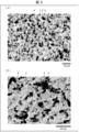
- FIG. 3 shows an example of a result of observing the surface and the cross section of the Fe-based sintered body according to one embodiment of the present invention manufactured by the above steps.
- FIG. 3 is a backscattered electron image obtained by observing a sample polished so that the material structure of the Fe-based sintered body according to one embodiment of the present invention can be observed.
- (B) is a backscattered electron image obtained by observing the cross section of the sample.
- the Fe-based sintered body has the above-described island-shaped composite structure (see FIG. 2). It can be seen that the hard phase 4 is also formed inside the Fe-based sintered body (sample cross section).
- the Fe-based sintered body of the present embodiment may be used for manufacturing a hot-pressing die, and the hot-pressing die manufactured using the Fe-based sintered body of the present embodiment may also be used. Included in the scope of the invention.
- a calcining step may be included between the forming step and a sintering step described below, and may not be included.
- fine carbon particles are added to the fine powder of Fe and the fine powder of TiB 2 and mixed, and the obtained mixed powder is molded to obtain a molded body.
- a calcination step is performed using the molded body.
- the Fe-based sintered body according to one embodiment of the present invention may be manufactured.
- Example preparation The fine powder of pure Fe having an average particle diameter of 3 to 5 ⁇ m and the fine powder of TiB 2 having an average particle diameter of 2 to 3 ⁇ m were dry-mixed at 100 rpm for 1 hour using a planetary ball mill.
- the ratio of pure Fe: TiB 2 was 80:20 by mass (70:30 by volume).
- ceramic balls (balls) were added at a ratio of 150 g to 15 g of the mixed powder to mix.
- the obtained mixed powder was filled in a graphite mold of a discharge sintering machine. Heating and energization were performed while applying pressure using a graphite punch, and electric discharge sintering was performed.
- the sintering temperature (maximum ultimate temperature) was 1273K to 1423K, and the pressure was 50 MPa.
- the heating rate was 100 k / min, and the holding time at the maximum attained temperature was approximately 0 seconds.
- the sample was taken out from the discharge sintering machine, polished, and then subjected to X-ray diffraction measurement, electron microscope observation, thermal conductivity measurement, density measurement, and hardness test.
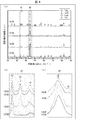
- FIG. 4 shows the measurement results.
- FIG. 4A is a view showing an example of an X-ray diffraction pattern obtained by performing a powder X-ray diffraction measurement on a powder sample produced at a sintering temperature of 1273 K to 1423 K using an X-ray diffractometer.
- FIG. 1 is an enlarged view of a diffraction angle 2 ⁇ of about 35 ° in the X-ray diffraction pattern
- (c) is an enlarged view of a diffraction angle 2 ⁇ of about 45 ° in the X-ray diffraction pattern.
- a circle corresponds to the diffraction peak of TiB 2
- a triangle corresponds to ⁇ Fe
- a square corresponds to the diffraction peak of Fe 2 B
- a triangle corresponds to the diffraction peak of TiC.
- FIG. 4B in the sample at the sintering temperature of 1273 K, clear peaks of TiC and Fe 2 B were not observed, and no TiC was generated.
- the samples having sintering temperatures of 1323 K, 1373 K, and 1423 K clear diffraction peaks of TiC and Fe 2 B were observed.
- the fact that the diffraction peaks of Fe 2 B are observed in the samples at the sintering temperatures of 1323 K, 1373 K and 1423 K can also be seen from the diffraction pattern shown in FIG. 4C.
- the electron microscope observation of the sample surface and the sample cross section was performed about each sample.
- the sample surface is a surface obtained by polishing a portion in contact with a graphite punch during spark sintering.
- the sample cross section is an internal portion of the Fe-based sintered body, and is a surface obtained by cutting the sintered body after sintering and polishing the cross section.
- a backscattered electron image was taken of the sample surface and the sample cross section, and a composition analysis was performed by wavelength dispersive X-ray analysis (WDX). Further, the concentration of TiB 2 was measured on the sample surface and the sample cross section by WDX. As a result, on both the sample surface and the sample cross section, the concentration of TiB 2 decreased as the sintering temperature increased (see FIG. 6 described later).
- WDX wavelength dispersive X-ray analysis
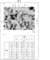
- FIG. 5 shows the results.
- FIG. 5A is a diagram showing a portion where a local WDX is performed in a backscattered electron image of a sample.
- FIG. 5B is a diagram showing the results of composition analysis at eight locations where WDX was performed.
- TiC exists together with the matrix 1 containing Fe as a main component.
- TiB 2 is present in the places (4) and (5) where the dark and light (black) particulate phase 2 is observed.
- Fe 2 B is present in the places (6) and (7) where the by-product phase 3 is observed, and almost all is Fe in the place (8) where the matrix 1 is observed.
- Thermal conductivity measurement, density measurement, hardness test The measurement of the thermal conductivity was performed using a stationary method (a method of applying a constant temperature gradient to the sample to be measured and measuring the thermal conductivity). That is, one of the samples to be measured was set to a high temperature and the other was set to a low temperature, and the temperature at each point in the sample was measured to obtain the thermal conductivity.
- the density measurement was performed using the Archimedes method.
- the relative density was determined by dividing the density measured by the Archimedes method by the theoretical density.
- the hardness test was performed by a Vickers hardness test on the sample surface and inside the sample, respectively.
- the test force was 30 kg and the holding time was 10 seconds.
- the Vickers hardness (HV) can be converted to Rockwell hardness (HRC) using the following conversion formula.
- Comparative Example 1 in which the sintering temperature is 1273 K, the thermal conductivity is about 44 W / (m ⁇ K) and the Vickers hardness is about 220 HV. In the sample of Comparative Example 1, no TiC was generated in the material structure, and the hard phase 4 for increasing the hardness was not present. Therefore, the sample of Comparative Example 1 shows high thermal conductivity due to heat conduction by the matrix 1, but has insufficient hardness.
- Examples 1 to 3 in which the sintering temperature was 1323 K to 1423 K, it was found that the higher the sintering temperature, the higher the hardness. Regarding thermal conductivity, Examples 1 and 2 are slightly inferior to Comparative Example 1. Although the reason for this is not clear, it is speculated that the solid solution of Ti and C in the matrix 1 may be one reason. The higher the sintering temperature, the more the diffusion of Ti and C is promoted, and the easier it is to form TiC.
- Examples 1 to 3 show that the higher the sintering temperature, the lower the TiB 2 concentration on the sample surface and inside the sample. It is considered that the greater the decrease in the TiB 2 concentration after sintering, the greater the amount of TiC generated. Also, the higher the sintering temperature, the higher the density and relative density.
- an Fe-based sintered body having both high hardness and high thermal conductivity can be manufactured more stably.
- the sample was manufactured by changing the sintering temperature from 1273K to 1423K while setting the holding time at the maximum attained temperature to approximately 0 seconds.
- the sample was manufactured by changing the sintering temperature to 1373 K and changing the holding time at the maximum attained temperature to approximately 0 seconds, 300 seconds, and 600 seconds.
- FIG. 7A shows an X-ray obtained by performing a powder X-ray diffraction measurement on a powder sample prepared under the conditions of a sintering temperature of 1373 K and a holding time of approximately 0 to 600 seconds using an X-ray diffractometer. It is a figure which shows an example of a diffraction pattern, (b) is a figure which expands and shows the diffraction angle 2 (theta) in the said X-ray diffraction pattern about 35 degrees, and (c) is a diffraction angle in the said X-ray diffraction pattern. It is a figure which expands and shows 2theta about 45 degrees.
- the Fe-based sintered body in one embodiment of the present invention can improve the thermal conductivity and the hardness by increasing the sintering temperature and increasing the holding time.
- the thermal conductivity and the hardness can be relatively easily controlled. Therefore, according to one embodiment of the present invention, it can be seen that an Fe-based sintered body having both high hardness and high thermal conductivity can be manufactured more stably.
- the samples were manufactured with the mass ratio of pure Fe: TiB 2 being 80:20.
- a sample was manufactured with the mass ratio of pure Fe: TiB 2 being 87:13 (Example 7).
- the sintering temperature was 1373 K, and the holding time at the maximum temperature was 600 seconds.
- a sample was manufactured under the same conditions as in the first embodiment described above.
- Various tests were performed in the same manner as in the first embodiment.
- FIG. 9A is a reflected electron image obtained by observing the material structure of the manufactured sample using an electron microscope.
- FIG. 9B is a table collectively showing the test results of the sample.
- the sample of this example has a matrix 1, a particulate phase 2, a by-product phase 3, and a hard phase 4, as in the first and second examples. ing. Then, as shown in FIG. 9B, even under the conditions of this embodiment, an Fe-based sintered body having both high hardness and high thermal conductivity can be obtained.
- the present embodiment is compared with the sixth embodiment (see FIG. 8) in the second embodiment, the following can be understood. That is, when the amount of TiB 2 charged is large, the hardness and the thermal conductivity are improved. Therefore, in the Fe-based sintered body according to one embodiment of the present invention, the thermal conductivity and the hardness can be relatively easily controlled by controlling the charged raw material ratio (the ratio of pure Fe: TiB 2 ). . Therefore, according to one embodiment of the present invention, it can be seen that an Fe-based sintered body having both high hardness and high thermal conductivity can be manufactured more stably.
- the present invention is not limited to the above-described embodiment, and various changes can be made within the scope shown in the claims.
- the present invention also relates to an embodiment obtained by appropriately combining the technical means disclosed in the above description. Included in the technical scope of the invention.
Landscapes
- Engineering & Computer Science (AREA)
- Mechanical Engineering (AREA)
- Chemical & Material Sciences (AREA)
- Manufacturing & Machinery (AREA)
- Materials Engineering (AREA)
- Metallurgy (AREA)
- Organic Chemistry (AREA)
- Physics & Mathematics (AREA)
- Optics & Photonics (AREA)
- Chemical Kinetics & Catalysis (AREA)
- Powder Metallurgy (AREA)
- Ceramic Products (AREA)
Abstract
L'invention concerne un corps fritté à base de Fe qui permet d'obtenir simultanément une dureté élevée et une conductivité thermique élevée et qui peut être produit de manière plus stable. Ce corps fritté à base de Fe comprend : une matrice (1) qui contient du Fe en tant que composant principal ; et une phase dure (4) qui est distribuée dans ladite matrice (1). La matrice (1) est formée à la manière d'un réseau et contient de l'αFe. La phase dure (4) contient du TiC.
Priority Applications (3)
| Application Number | Priority Date | Filing Date | Title |
|---|---|---|---|
| US17/266,375 US11858045B2 (en) | 2018-08-07 | 2019-07-24 | Fe-based sintered body, Fe-based sintered body production method, and hot-pressing die |
| EP19846080.0A EP3835443A4 (fr) | 2018-08-07 | 2019-07-24 | Corps fritté à base de fe, procédé de production de corps fritté à base de fe et matrice de pressage à chaud |
| CN201980052043.5A CN112567060B (zh) | 2018-08-07 | 2019-07-24 | Fe基烧结体、Fe基烧结体的制造方法以及热压用金属模 |
Applications Claiming Priority (2)
| Application Number | Priority Date | Filing Date | Title |
|---|---|---|---|
| JP2018-148885 | 2018-08-07 | ||
| JP2018148885A JP7100320B2 (ja) | 2018-08-07 | 2018-08-07 | Fe基焼結体、Fe基焼結体の製造方法、および熱間プレス用金型 |
Publications (1)
| Publication Number | Publication Date |
|---|---|
| WO2020031702A1 true WO2020031702A1 (fr) | 2020-02-13 |
Family
ID=69414805
Family Applications (1)
| Application Number | Title | Priority Date | Filing Date |
|---|---|---|---|
| PCT/JP2019/029057 Ceased WO2020031702A1 (fr) | 2018-08-07 | 2019-07-24 | Corps fritté à base de fe, procédé de production de corps fritté à base de fe et matrice de pressage à chaud |
Country Status (5)
| Country | Link |
|---|---|
| US (1) | US11858045B2 (fr) |
| EP (1) | EP3835443A4 (fr) |
| JP (1) | JP7100320B2 (fr) |
| CN (1) | CN112567060B (fr) |
| WO (1) | WO2020031702A1 (fr) |
Families Citing this family (1)
| Publication number | Priority date | Publication date | Assignee | Title |
|---|---|---|---|---|
| CN114974731B (zh) * | 2022-05-13 | 2025-09-30 | 合肥工业大学 | 一种纳米Fe3C颗粒复合碳基导电膜及其制备方法 |
Citations (9)
| Publication number | Priority date | Publication date | Assignee | Title |
|---|---|---|---|---|
| JPS4829965B1 (fr) * | 1970-12-28 | 1973-09-14 | ||
| JPS4998307A (fr) * | 1972-12-29 | 1974-09-18 | ||
| JPS62177159A (ja) * | 1986-01-30 | 1987-08-04 | Mazda Motor Corp | 耐摩耗性に優れた焼結合金部材 |
| JPH02263947A (ja) * | 1989-04-03 | 1990-10-26 | Tokushu Denkyoku Kk | 炭火物を分散した高強度鋼の製造方法 |
| JPH0317246A (ja) * | 1984-03-12 | 1991-01-25 | General Electric Co <Ge> | 炭化チタンを使用した耐固体粒子浸食性の製品 |
| JP2000273503A (ja) * | 1999-03-25 | 2000-10-03 | Kobe Steel Ltd | 硬質粒分散焼結鋼及びその製造方法 |
| US6652616B1 (en) * | 1999-09-16 | 2003-11-25 | Maschienfabrik Koppern Gmbh & Co. Kg | Powder metallurgical method for in-situ production of a wear-resistant composite material |
| JP2015221941A (ja) | 2006-08-09 | 2015-12-10 | ロバルマ, ソシエダッド アノニマRovalma, S.A. | 鋼、工具鋼、特に熱間加工鋼の熱伝導度の調整方法、並びに鋼製品 |
| JP2018053308A (ja) * | 2016-09-28 | 2018-04-05 | マツダ株式会社 | ダイカスト金型用銅含有鉄系焼結合金、その製造方法、及び当該ダイカスト金型用銅含有鉄系焼結合金を用いて製造されたダイカスト金型 |
Family Cites Families (9)
| Publication number | Priority date | Publication date | Assignee | Title |
|---|---|---|---|---|
| BE791741Q (fr) | 1970-01-05 | 1973-03-16 | Deutsche Edelstahlwerke Ag | |
| JPS5020947B1 (fr) | 1970-01-19 | 1975-07-18 | ||
| US3796111A (en) | 1971-08-18 | 1974-03-12 | Sundstrand Corp | Hydromechanical multi-range transmission |
| DE2244470C3 (de) * | 1972-09-11 | 1975-03-13 | Deutsche Edelstahlwerke Ag, 4150 Krefeld | Hochkorrosionsbeständige und -verschleißfeste Sinterstahllegierung |
| US3999952A (en) * | 1975-02-28 | 1976-12-28 | Toyo Kohan Co., Ltd. | Sintered hard alloy of multiple boride containing iron |
| US4704336A (en) * | 1984-03-12 | 1987-11-03 | General Electric Company | Solid particle erosion resistant coating utilizing titanium carbide |
| JP3032818B2 (ja) * | 1998-05-11 | 2000-04-17 | 工業技術院長 | チタン硼化物分散硬質材料 |
| CN100494443C (zh) | 2007-08-07 | 2009-06-03 | 广西大学 | 原位反应铸造法制备TiCp/Fe复合材料的低温加钛法 |
| CN101525716B (zh) * | 2009-04-21 | 2011-04-20 | 合肥工业大学 | 铁铝金属间化合物-二硼化钛复合材料及制备方法 |
-
2018
- 2018-08-07 JP JP2018148885A patent/JP7100320B2/ja active Active
-
2019
- 2019-07-24 WO PCT/JP2019/029057 patent/WO2020031702A1/fr not_active Ceased
- 2019-07-24 EP EP19846080.0A patent/EP3835443A4/fr active Pending
- 2019-07-24 US US17/266,375 patent/US11858045B2/en active Active
- 2019-07-24 CN CN201980052043.5A patent/CN112567060B/zh active Active
Patent Citations (9)
| Publication number | Priority date | Publication date | Assignee | Title |
|---|---|---|---|---|
| JPS4829965B1 (fr) * | 1970-12-28 | 1973-09-14 | ||
| JPS4998307A (fr) * | 1972-12-29 | 1974-09-18 | ||
| JPH0317246A (ja) * | 1984-03-12 | 1991-01-25 | General Electric Co <Ge> | 炭化チタンを使用した耐固体粒子浸食性の製品 |
| JPS62177159A (ja) * | 1986-01-30 | 1987-08-04 | Mazda Motor Corp | 耐摩耗性に優れた焼結合金部材 |
| JPH02263947A (ja) * | 1989-04-03 | 1990-10-26 | Tokushu Denkyoku Kk | 炭火物を分散した高強度鋼の製造方法 |
| JP2000273503A (ja) * | 1999-03-25 | 2000-10-03 | Kobe Steel Ltd | 硬質粒分散焼結鋼及びその製造方法 |
| US6652616B1 (en) * | 1999-09-16 | 2003-11-25 | Maschienfabrik Koppern Gmbh & Co. Kg | Powder metallurgical method for in-situ production of a wear-resistant composite material |
| JP2015221941A (ja) | 2006-08-09 | 2015-12-10 | ロバルマ, ソシエダッド アノニマRovalma, S.A. | 鋼、工具鋼、特に熱間加工鋼の熱伝導度の調整方法、並びに鋼製品 |
| JP2018053308A (ja) * | 2016-09-28 | 2018-04-05 | マツダ株式会社 | ダイカスト金型用銅含有鉄系焼結合金、その製造方法、及び当該ダイカスト金型用銅含有鉄系焼結合金を用いて製造されたダイカスト金型 |
Also Published As
| Publication number | Publication date |
|---|---|
| CN112567060A (zh) | 2021-03-26 |
| JP7100320B2 (ja) | 2022-07-13 |
| US11858045B2 (en) | 2024-01-02 |
| JP2020023733A (ja) | 2020-02-13 |
| EP3835443A1 (fr) | 2021-06-16 |
| EP3835443A4 (fr) | 2022-07-20 |
| US20210308756A1 (en) | 2021-10-07 |
| CN112567060B (zh) | 2022-04-12 |
Similar Documents
| Publication | Publication Date | Title |
|---|---|---|
| Farvizi et al. | Fabrication of NiTi and NiTi-nano Al2O3 composites by powder metallurgy methods: Comparison of hot isostatic pressing and spark plasma sintering techniques | |
| Panov | Nanostructured sintered WC–Co hard metals | |
| US20140178139A1 (en) | Method of manufacturing super hard alloy containing carbon nanotubes, super hard alloy manufactured using same, and cutting tool comprising super hard alloy | |
| Wang et al. | Microstructure and preparation of an ultra-fine-grained W-Al2O3 composite via hydrothermal synthesis and spark plasma sintering | |
| CN110387496B (zh) | 一种表层无TiC相的WC-TiC-Co基梯度硬质合金及其制备方法 | |
| WO2013089177A1 (fr) | Alliage thermorésistant et procédé de fabrication de celui-ci | |
| Cramer et al. | In-situ metal binder-phase formation to make WC-FeNi Cermets with spark plasma sintering from WC, Fe, Ni, and carbon powders | |
| Zhang et al. | Spark plasma sintering of Al2O3–Ni nanocomposites using Ni nanoparticles produced by rotary chemical vapour deposition | |
| CN102596851B (zh) | 碳材料及其制造方法 | |
| KR101186456B1 (ko) | 금속 복합분말, 소결체 및 이의 제조 방법 | |
| JP6615108B2 (ja) | 高温耐酸化性のレアメタルフリー硬質焼結体およびその製造方法 | |
| Sethi et al. | The effect of milling time, and sintering temperature and time on the microstructure-property relationship of aluminium-matrix hybrid composites | |
| WO2020031702A1 (fr) | Corps fritté à base de fe, procédé de production de corps fritté à base de fe et matrice de pressage à chaud | |
| JP7157887B1 (ja) | 粉砕・撹拌・混合・混練機部材 | |
| JP2017186624A (ja) | 超硬合金及びその製造方法、並びに超硬工具 | |
| Jing et al. | Reaction synthesis of Fe–(Ti, V) C composites | |
| Santanach et al. | Spark plasma sintering as a reactive sintering tool for the preparation of surface-tailored Fe–FeAl2O4–Al2O3 nanocomposites | |
| JP2012087042A (ja) | 二硼化チタン系焼結体及びその製造方法 | |
| Jiang et al. | Parameters investigation during simultaneous synthesis and densification WC–Ni composites by field-activated combustion | |
| JP2004142993A (ja) | 六方晶複合炭化物およびその製造方法 | |
| Amiri-Moghaddam et al. | In-situ synthesis of WC–X% Co composite in the WO3–Co3O4–C system by carbothermal reduction method | |
| JP4809096B2 (ja) | TiB2基Ti−Si−C系複合セラミックス及びその焼結体製造方法 | |
| Zhang et al. | Bulk Mo2FeB2 based cermets fabricated by mechanical ball milling and reaction boronizing sintering | |
| KR20150043276A (ko) | 탄소나노튜브를 포함하는 초경합금의 제조방법, 이에 의해 제조된 초경합금 및 초경합금을 포함하여 이루어지는 초경 절삭공구 | |
| Yue et al. | Synthesis and comparison of Two cBN composites with starting ternary carbide binders |
Legal Events
| Date | Code | Title | Description |
|---|---|---|---|
| 121 | Ep: the epo has been informed by wipo that ep was designated in this application |
Ref document number: 19846080 Country of ref document: EP Kind code of ref document: A1 |
|
| NENP | Non-entry into the national phase |
Ref country code: DE |
|
| ENP | Entry into the national phase |
Ref document number: 2019846080 Country of ref document: EP Effective date: 20210309 |